

Page 1
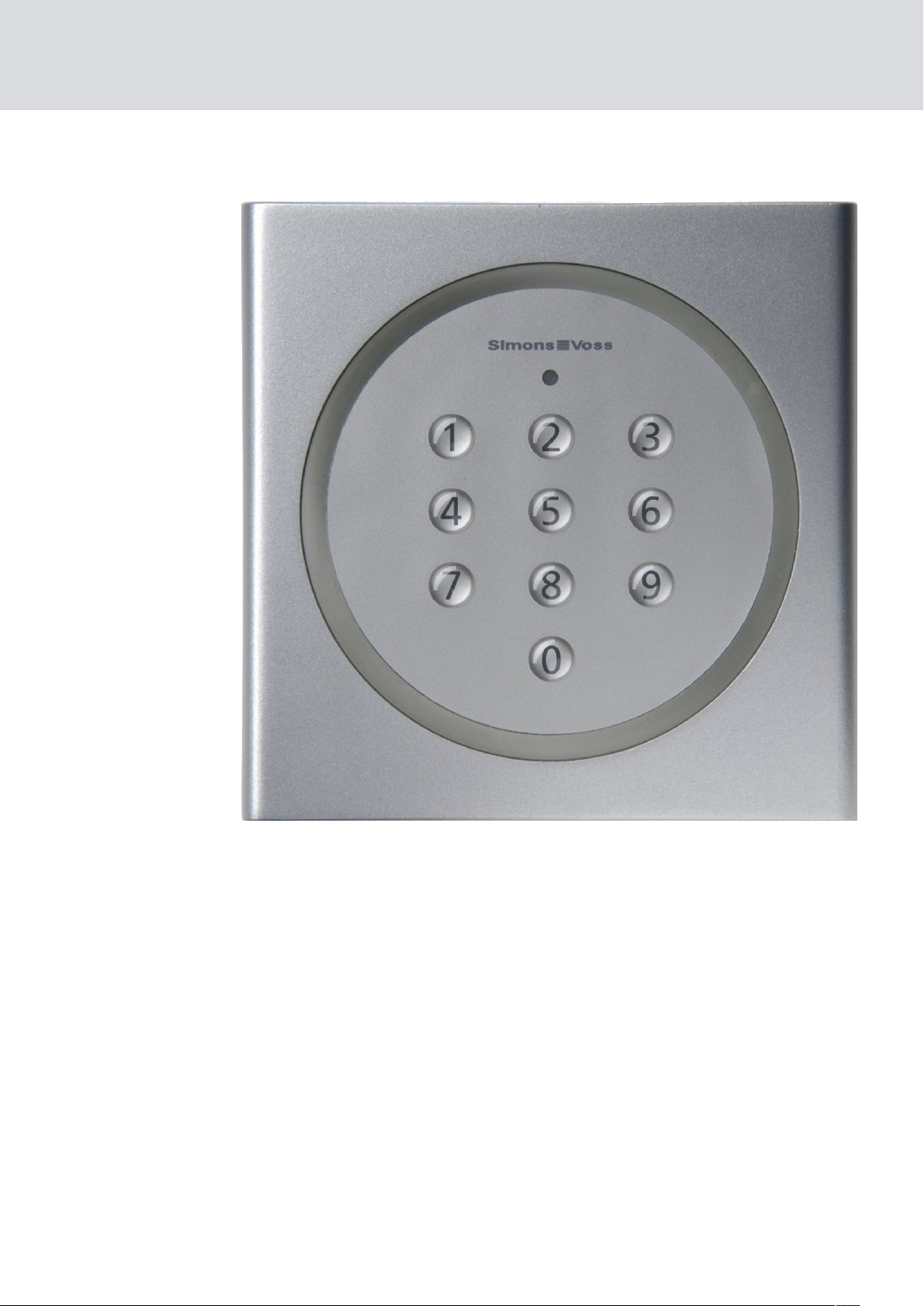
PinCode Keypad
Manual
14.05.2019
Page 2

Contents
PinCode Keypad (Manual)
2 / 28
Contents
1 General information .................................................................................................................................. 3
1.1 Intended use....................................................................................................................................................... 3
1.2 Safety instructions...........................................................................................................................................4
2 How it works ................................................................................................................................................5
2.1 Overview............................................................................................................................................................... 5
2.2 Operating modes ............................................................................................................................................. 5
2.3 Operation.............................................................................................................................................................6
2.3.1 Opening................................................................................................................................................ 7
3 Initial operation...........................................................................................................................................8
4 PINs ................................................................................................................................................................9
4.1 Changing of the Master PIN........................................................................................................................ 9
4.2 Programming PINs ........................................................................................................................................10
4.3 Deleting PINs......................................................................................................................................................11
5 Transponder ...............................................................................................................................................13
5.1 Programming the transponders ..............................................................................................................13
5.2 Reading out the transponders................................................................................................................. 15
5.3 Resetting transponders .............................................................................................................................. 16
6 Signal ........................................................................................................................................................... 18
7 Battery replacement .............................................................................................................................. 20
8 Special functions .....................................................................................................................................22
8.1 Double-click simulation (block lock operation on block lock 3066)...................................22
8.2 Other information ..........................................................................................................................................23
9 Technical specifications........................................................................................................................24
10 Declaration of conformity .....................................................................................................................25
11 Help and other information ................................................................................................................. 26
Page 3
PinCode Keypad (Manual)
1 General information
1. General information
3 / 28
1.1 Intended use
The PIN code keypad can be used to activate SimonsVoss locking devices
such as locking cylinders, SmartHandles or SmartRelays,
numerical code.
The PIN code keypad is integrated into the locking system using the
corresponding locking system software.
The PIN code keypad can store up to 3 User PINs, which can be
regarded as 3 separate transponders.
User PINs may contain between 4 and 8 characters.
You can configure User PINs directly on the PIN code keypad by entering
the Master PIN first.
by entering a
Page 4

PinCode Keypad (Manual)
1.2 Safety instructions
The batteries used may pose a fire or burn hazard if handled incorrectly.
Do not recharge, open, heat or burn these batteries. Do not short-circuit!
Dispose of old or used batteries correctly. Store out of children's reach.
The electronics must not be subject to mechanical stress or damaged in
any way.
The product must not be soiled or scratched and must not be subjected
to strong impacts.
Only trained specialists may carry out installation and programming or
replace the batteries.
Access through a door may be blocked due to defective or incorrectly
programmed products. SimonsVoss Technologies GmbH is not liable
for any consequences, such as blocked access to injured persons or
those at risk, physical damage or any other losses.
1. General information
4 / 28
The Master PIN is a central component of the safety concept of the PIN
code keypad. After a loss of the Master PIN, no more administrative
changes can be made to the PIN code keypad. Keep the Master PIN in a
safe place and make it possible to view the Master PIN at all times.
SimonsVoss Technologies GmbH accepts no liability for any damage
caused by incorrect fitting or installation.
Modifications or further technical developments cannot be excluded
and may be implemented without notice.
This documentation has been compiled based on the best knowledge
available to us. Nevertheless, errors cannot be ruled out. SimonsVoss
Technologies GmbH accepts no liability in such a case.
Should there be differences in the content of other language versions of
this documentation, the German version applies in cases of doubt.
Page 5

PinCode Keypad (Manual)
2 How it works
The PIN code keypad is a digital key that opens SimonsVoss locking
devices via radio once the correct PINs have been entered. The PIN code
keypad uses one of the three integrated transponders for this purpose.
To configure the system, at least one PIN must be programmed (see
Programming PINs [}10]
must be programmed to match the desired locking device (see
Programming the transponders [}13]
The PIN code keypad is IP65 protected and therefore also suitable for
outdoor use. Due to the battery supply, it can be installed wirelessly
independently of existing power connections. It can be programmed with
the LSM software and used seamlessly in the System 3060.
2. How it works
5 / 28
)) and the associated integrated transponder
).
2.1 Overview
The PIN code keypad consists of two components:
PIN code input field with evaluation
Integrated transponders
If the PIN entered in the input field is recognised as correct, the input field
triggers the corresponding integrated transponder.
With the PIN code keypad, you can operate all SimonsVoss locking devices
(such as SmartRelays, cylinders, SmartHandles and activation units, etc.)
with the PIN code keypad at any time. You can create up to three
independent user groups. If you carry out a reprogramming that only
affects one user group, you only have to inform this user group.
If you use SimonsVoss locking devices with ZK function (access and time
zone control), you can also grant a person or user group temporary rights to
the locking device. You can also log which PIN was used when to operate a
locking device.
You can operate the same locking device with different User PINs. Since
you give each user group a different User PIN, you can grant the user groups
different access rights.
Conversely, it is not possible to control different locking devices with the
same PIN code keypad via different User PINs, as the signal is sent to all
locking devices simultaneously. This does not ensure that the locking
device that matches the User PIN entered is addressed. In this case, the
locking device is not operated although the correct User PIN has been
entered.
2.2 Operating modes
The PIN code keypad differentiates between four operating modes.
Page 6
PinCode Keypad (Manual)
Status Explanation
2. How it works
6 / 28
Standby
Opening
Programming
Battery warning
Sleep mode. The PIN code keypad
consumes very little energy.
Active mode. The PIN code keypad
checks the input and, if the input is
correct, actuates the locking device
via radio (see
Operation [}6]
PIN programming: The individual
PINs (max. three) are programmed/
reset directly via the keyboard (see
PIN programming).
PINs [}10]
Transponder programming: The associated integrated transponders
(max. three) are programmed/reset
via the LSM software (see
ming the transponders [}13]
Low battery. A two-stage battery
warning system signals you in good
time when you need to change the
battery (see
tery replacement [}20]
How it works [}5]
).
Programming
).
Signal [}18]
).
Program-
).
und
Bat-
and
IMPORTANT
Locked programming with low battery
If the battery warning is active, you cannot change the programming of the
PIN code keypad. You cannot change or delete any User PIN.
1. Replace the batteries (see
2. Perform the desired change.
Battery replacement [}20]
).
2.3 Operation
Once you have put the PIN code keypad into operation and programmed it,
the PIN code keypad, together with a SimonsVoss locking device, forms a
so-called "mental lock" in System 3060.
You programme the PINs directly on the PIN code keypad, while you
programme the integrated transponders with the LSM software and thus
integrate them into the System 3060.
Page 7

PinCode Keypad (Manual)
2.3.1 Opening
You open the locking device to which the integrated transponder has been
assigned as follows:
ü At least one PIN programmed.
ü At least one integrated transponder assigned to the locking device.
Enter a previously programmed PIN.
IMPORTANT
Duration of input
A too long period of time between the entries terminates the entry.
Enter the digits less than five seconds apart.
2. How it works
7 / 28
9 If you have entered a correct PIN, the PIN code keypad signals with
two green flashes and beeps that the entry was correct.
9 Integrated transponder activates the locking device.
Page 8

PinCode Keypad (Manual)
3 Initial operation
Initial operation is performed in three steps.
3. Initial operation
8 / 28
1. Change the master PIN (see
2. Programme one or more PINs (see
3. Authorise the assigned transponders on the locking device
(
Programming the transponders [}13]
Changing of the Master PIN [}9]
Programming PINs [}10]
).
).
).
Page 9
PinCode Keypad (Manual)
4 PINs
The PIN code keypad distinguishes between one Master PIN and up to
three User PINs. With the Master PIN it is possible to make changes to the
programming of the PIN code keypad, with the User PINs it is possible to
operate the assigned locking device.
IMPORTANT
Enter the numbers consecutively. The PIN code keypad only signals the
pressing of the keys, but not completion of the individual steps in the process.
IMPORTANT
4. PINs
9 / 28
Cancellation of actions
All actions can be cancelled by not making any further inputs. The PIN code
keypad will cancel the action after a waiting period.
IMPORTANT
Battery warning locks programming
If one of the two battery warning levels is active, the programming cannot
be changed.
1. Replace the batteries (see
2. Change the programming as required.
Battery replacement [}20]
).
4.1 Changing of the Master PIN
The Master PIN is only used to change the programming on the PIN code
keypad. You cannot operate any locking devices with the Master PIN.
ATTENTION
Master PIN loss
The Master PIN is an essential, integral part of the PIN code keypad security
concept. No more administrative changes can be made to the PIN code
keypad if the Master PIN is lost.
1. Keep the Master PIN in a safe place.
2. Make the Master PIN visible at any time.
You only have to change the Master PIN during initial operation, after which
the change is optional.
1. Enter the number sequence 0000.
Page 10

Enter 0000
Enter the old master PIN
Enter the new master PIN
Enter the new master PIN
(repeat)
PinCode Keypad (Manual)
2. Enter the old Master PIN (factory setting: 12345678).
3. Enter the new Master PIN.
IMPORTANT
Requirements for the Master PIN
The Master PIN must be secure. It must therefore meet the following requirements.
1. The Master PIN must consist of eight characters.
2. The digits of the Master PIN must not be consecutive.
3. The Master PIN must not begin with 0.
4. Enter the new Master PIN again.
9 PIN code keypad beeps and flashes green twice.
4. PINs
10 / 28
9 Master PIN is changed.
4.2 Programming PINs
You can programme up to three User PINs in the PIN code keypad.
Each User PIN behaves like its own transponder. The individual User PINs
must therefore be programmed separately in the respective transponders.
If you do not want to use all User PINss, leave them unprogrammed.
1. Enter the number sequence 0.
2. Enter the Master PIN.
3. Enter the number of the User PIN (for example, 1 for User PIN no. 1).
4. Specify the number that determines the length of the User PIN (for
example, 4 for a four-digit User PIN).
5. Enter the new User PIN.
Page 11

Enter XXXX
(New user PIN)
Enter the master PIN
Enter 3
(for user PIN 3)
Enter 2
(for user PIN 2)
Enter 1
(for user PIN 1)
Enter 0
Enter 4,5,6,7 or 8
(Length of the user PIN)
PinCode Keypad (Manual)
IMPORTANT
Requirements for the User PIN
The User PIN must be secure. It must therefore meet the following requirements:
1. The User PIN must consist of four to eight characters.
2. The digits of the User PIN must not be consecutive.
3. The digits of the User PIN may not be identical.
4. The User PIN must not begin with 0.
5. The User PINs may not be identical.
9 PIN code keypad beeps and flashes green twice.
9 User PIN is programmed.
4. PINs
11 / 28
Repeat the process to programme other User PINs in the PIN code keypad.
4.3 Deleting PINs
You can delete a User PIN by setting the length of the User PIN to zero.
1. Enter the number sequence 0.
2. Enter the Master PIN.
3. Enter the number of the User PIN (for example, 1 for User PIN no. 1).
4. Specify the number that determines the length of the User PIN (0 in this
case).
9 PIN code keypad beeps and flashes green twice.
9 User PIN is deleted.
Page 12

Enter 2
(for user PIN 2)
Enter 3
(for user PIN 3)
Enter 1
(for user PIN 1)
Enter 0
(Length of the user PIN)
Enter the master PIN
Enter 0
PinCode Keypad (Manual)
Deleted User PINs can no longer be used to operate the locking device.
If you do not want to use all User PINss, leave them unprogrammed.
4. PINs
12 / 28
Page 13

PinCode Keypad (Manual)
5 Transponder
Each User PIN is assigned to one of the three integrated transponders. If
you want to use and differentiate between the different User PINs, you
must programme the integrated transponders individually (see
Programming the transponders [}13]
Each of the three integrated transponders has its own transponder ID
(TID). This TID is stored in the locking device when a ZK (access and time
control) locking device is activated. This allows you to see which PIN
operated which locking device and when.
IMPORTANT
Enter the numbers consecutively. The PIN code keypad only signals the
pressing of the keys, but not completion of the individual steps in the process.
5. Transponder
13 / 28
).
IMPORTANT
Cancellation of actions
All actions can be cancelled by not making any further inputs. The PIN code
keypad will cancel the action after a waiting period.
IMPORTANT
Battery warning locks programming
If one of the two battery warning levels is active, the programming cannot
be changed.
1. Replace the batteries (see
2. Change the programming as required.
Battery replacement [}20]
).
5.1 Programming the transponders
Each PIN is assigned to one of the three integrated transponders.
PIN Transponder
User PIN 1 Transponder 1
User PIN 2 Transponder 2
User PIN 3 Transponder 3
Page 14

PinCode Keypad (Manual)
IMPORTANT
No access due to incorrect assignment
If you do not observe the assignment, a user may not be able to use their
User PIN.
1. When programming, select the correct number of the corresponding
User PIN!
2. Check the assignment after programming by activating a locking device
(see
Opening [}7]
Create entry for the User PIN
1. In the LSM software (same locking plan), click on the button New
transponder .
9 The window "New transponder" opens.
5. Transponder
14 / 28
).
2. In the dropdown menu Type select the entry "G1 Pin code".
3. Click on the OK button.
9 Window closes.
9 The entry for User PIN is created.
Repeat these steps for all other User PINs that you want to create.
Programming PIN code keypad
1. Select the User PIN entry in the matrix.
2. Open the context menu by right-clicking on the entry of the User PIN in
the matrix.
3. Select the context menu entry Programming .
9 The window "Transponder Programming" opens.
4. Enter the number sequence 00.
5. Enter the Master PIN.
6. Click on the Programming button.
7. Enter the number of the User PIN (for example, 1 for User PIN no. 1).
IMPORTANT
Radio error
If you hold the transponder too close to the programming device or activate the transponder too early, the radio link cannot be established.
1. Keep a distance of about 20 cm!
2. Do not activate the transponder until you are prompted in the LSM
software to press the transponder button.
9 Programming is performed.
9 PIN code keypad beeps and flashes green twice.
Page 15

Set up transponder
(LSM software: "G1 PinCode")
Open the programming menu
(LSM software: "Programme")
Start programming
(LSM software: "Programme")
Enter 1,2 or 3
(Number of the transponder)
Enter the master PIN
Enter 00
PinCode Keypad (Manual)
9 "Programming successful" window is displayed.
9 User PIN was linked to the entry in the matrix.
Repeat the programming for all other User PINs that you want to assign.
If you do not want to use all User PINss, leave them unprogrammed.
5. Transponder
15 / 28
5.2 Reading out the transponders
You can read out the integrated transponders.
1. Click the button Read transponder .
9 The window "Programming" opens.
2. Enter the User PIN whose transponder you want to read out.
IMPORTANT
Radio error
If you hold the transponder too close to the programming device or activate the transponder too early, the radio link cannot be established.
1. Keep a distance of about 20 cm!
2. Do not activate the transponder until you are prompted in the LSM
software to press the transponder button.
9 The transponder is read out.
9 PIN code keypad beeps and flashes green twice.
Page 16

Open the readout menu
(LSM software: "Read out transponder")
Enter user PIN
(is read out)
PinCode Keypad (Manual)
9 The window "Read transponder data" opens.
5.3 Resetting transponders
You can reset the integrated transponders at any time using the LSM
software.
5. Transponder
16 / 28
1. Read out the transponder that you want to reset (see
transponders [}15]
).
Reading out the
2. Enter the number sequence 00.
3. Enter the Master PIN.
4. Click on the Reset button.
9 The window "LockSysMgr" opens.
5. Click on the Yes button.
9 Window closes.
6. Enter the number of the User PIN (for example, 1 for User PIN no. 1).
9 PIN code keypad beeps and flashes green twice.
IMPORTANT
Radio error
If you hold the transponder too close to the programming device or activate the transponder too early, the radio link cannot be established.
1. Keep a distance of about 20 cm!
2. Do not activate the transponder until you are prompted in the LSM
9 The window "Programming" opens.
9 The transponder is reset.
software to press the transponder button.
Page 17

Enter the master PIN
Enter the master PIN
Enter the master PIN
Enter 1,2 or 3
(Number of the transponder)
Start reset
(LSM software: “Reset”)
Reading transponders
PinCode Keypad (Manual)
5. Transponder
17 / 28
Page 18

PinCode Keypad (Manual)
6 Signal
LED flashing beeper Meaning Cause
6. Signal
18 / 28
1 x green, short 1× Number entry
Transponder, active
Programming successful
2 x green, short 2×
Reset successful
Master PIN changed
1× red, long 1× long Incorrect entry
You have entered a
number.
You have entered a
correct PIN.
You have successfully programmed
an integrated
transponder.
You have successfully reset an integrated transponder.
You have successfully changed the
Master PIN.
You have entered an
incorrect User PIN or
the incorrect Master
PIN.
Yellow (1 Hz)
beeping (1 Hz)
Duration: 10 s
Battery Warning
Level 1
The batteries PIN
code keypad are
low. The PIN code
keypad operates the
locking device only
after a delay of ten
seconds. Replace
the batteries (see
Battery replacement
[}20]
to the programming
are no longer possible until the battery is changed.
). Changes
Page 19

PinCode Keypad (Manual)
LED flashing beeper Meaning Cause
The batteries PIN
code keypad are
very low. The PIN
code keypad operates the locking
device only after a
delay of twenty
seconds. Change the
batteries immediately (see
replacement
[}20]
the PIN code keypad
may not function.
Changes to the programming are no
longer possible until
the battery is
changed.
Yellow (1 Hz)
beeping (1 Hz)
Duration: 20 s
Battery Warning
Level 2
6. Signal
19 / 28
Battery
), otherwise
Red (1 Hz)
beeping (1 Hz)
Duration: 60 s
Multiple incorrect
entry
You have entered an
incorrect User PIN or
the incorrect Master
PIN multiple times.
The PIN code
keypad beeps and
flashes red for 60
seconds. You cannot
make any entries
during this time.
Then enter a correct
User PIN or one that
Master PIN.
Page 20

PinCode Keypad (Manual)
7 Battery replacement
To change the batteries, you must open the housing of the PIN code
keypad. For this you need a Torx screwdriver size 6 (not included in
delivery)!
ATTENTION
Damage to the electronics due to fluids or static discharge
Do not touch electronics/components; do not allow them to come into
contact with oil, paint, moisture, alkali or acids.
IMPORTANT
7. Battery replacement
20 / 28
Do not touch the contacts on the new batteries with your hands when replacing the old ones. Use cotton gloves free of fat or grease.
1. Unscrew the two screws in the bottom of the housing completely.
2. Remove the front of the housing.
3. Using a screwdriver, slide one side of the battery brackets into the
designated opening.
ATTENTION
The spring tension of the clamps causes the clamps to jump out.
The clamps are under tension. They can jump out and get lost when you
release them.
4. Remove the battery.
5. Remove all other batteries in the same way.
IMPORTANT
All batteries are discharged at approximately the same rate. Therefore, replace all batteries at the same time.
6. Insert the new batteries with the positive pole facing upward (Sony,
Panasonic or Varta CR2032 (3V) batteries).
Page 21

PinCode Keypad (Manual)
7. Carefully hook the battery clips back into the circuit board.
8. Replace the front of the housing.
9. Screw the two screws back in the bottom of the housing completely.
9 The batteries have been replaced.
7. Battery replacement
21 / 28
Page 22

PinCode Keypad (Manual)
8 Special functions
8.1 Double-click simulation (block lock operation on block lock 3066)
You can use the PIN code keypad for activating SimonsVoss activation
units (VdS block lock 3066). If a correct PIN has been entered, the
activation unit is addressed. The block lock then activates or deactivates
the alarm system. You can meet the requirements of VdS Class C to SG6
with the integration of a so-called mental lock.
The VdS-certified SimonsVoss activation units require a double opening
protocol for activation/deactivation (= double click if a transponder is to be
used to activate or deactivate). The PIN code keypad can simulate this
double-click and thus perform activation/deactivation operations. The
double-click simulation is not activated by default.
8. Special functions
22 / 28
For this, you must mount the PIN code keypad within the transmitting
range of the activation unit. You can then activate the double-click
simulation.
ATTENTION
Malfunctions due to double-click simulation
The double-click simulation is only intended for operation with a SimonsVoss 3066 block lock. It may cause other components to malfunction.
Only activate the double-click simulation if you are using a SimonsVoss
3066 block lock!
IMPORTANT
Cancellation of actions
All actions can be cancelled by not making any further inputs. The PIN code
keypad will cancel the action after a waiting period.
IMPORTANT
Enter the numbers consecutively. The PIN code keypad only signals the
pressing of the keys, but not completion of the individual steps in the process.
Page 23

PinCode Keypad (Manual)
IMPORTANT
Battery warning locks programming
If one of the two battery warning levels is active, the programming cannot
be changed.
8. Special functions
23 / 28
1. Replace the batteries (see
2. Change the programming as required.
Activate double-click simulation
1. Enter the number sequence 000.
2. Enter the Master PIN.
3. Enter the number sequence 92.
9 PIN code keypad beeps and flashes green twice.
9 Double-click simulation is activated.
Deactivate double-click simulation
1. Enter the number sequence 000.
2. Enter the Master PIN.
3. Enter the number sequence 91.
9 PIN code keypad beeps and flashes green twice.
9 Double-click simulation is deactivated.
Battery replacement [}20]
).
8.2 Other information
The following transponder functions are not available with the PIN code
keypad:
Quasiproximity
Validity mode
Expiry mode
Page 24

PinCode Keypad (Manual)
9 Technical specifications
Dimensions 96 mm × 96 mm × 14 mm
9. Technical specifications
24 / 28
2× CR 2032 (3V)
Batteries:
Always replace all batteries with new, approved,
brand-name batteries when changing them.
Sony
Authorised battery
manufacturers:
Battery life:
Distance to cylinder: Max. 40 cm
Distance to SmartRelay: Max. 120 cm
Protection class: IP 65
Operating temperature: -20 °C to +50 °C
Signal elements:
Marking: PHI number (physical hardware identifier)
Colour (housing)
Varta
Panasonic
Up to 100,000 operations or up to 10 years on
standby
Different colour LEDs (red, green, yellow) + audible signals
Silver-coloured ABS plastic housing similar to
RAL 9007 using formula 19900841
semitransparent back wall/base plate
Colour (key labelling): Anthracite grey similar to RAL 7016
Radio emissions
SRD 24.50 kHz - 25.06 kHz
There are no geographical restrictions within the EU.
-20 dBµA/m (10 m distance)
Page 25

PinCode Keypad (Manual)
10 Declaration of conformity
The company SimonsVoss Technologies GmbH hereby declares that
article TRA.PINCODE complies with the following guidelines:
2014/53/EU "Radio equipment"
2014/30/EU "EMC"
2011/65/EU "RoHS"
2012/19/EU "WEEE"
and regulation (EG) 1907/2006 "REACH"
The full text of the EU Declaration of conformity is available at the
following internet address:
certificates.html
10. Declaration of conformity
25 / 28
https://www.simons-voss.com/en/
.
Page 26

PinCode Keypad (Manual)
11 Help and other information
Information material/documents
You will find detailed information on operation and configuration and other
documents under Informative material/Documents in the Download
section on the SimonsVoss website (
downloads/documents.html
Declarations of conformity
You will find declarations of conformity for this product in the Certificate
section on the SimonsVoss website (
certificates.html
Information on disposal
11. Help and other information
26 / 28
https://www.simons-voss.com/en/
).
https://www.simons-voss.com/en/
).
Do not dispose the device (TRA.PINCODE) in the household waste.
Dispose of it at a collection point for electronic waste as per European
Directive 2012/19/EU.
Recycle defective or used batteries in line with European Directive
2006/66/EC.
Observe local regulations on separate disposal of batteries.
Take the packaging to an environmentally responsible recycling point.
Hotline
If you have any questions, the SimonsVoss Service Hotline will be happy to
help you on +49 (0)89 99 228 333 (German fixed network; call charges
vary depending on the operator).
Email
You may prefer to send us an email.
support@simons-voss.com
FAQs
You will find information and help for SimonsVoss products in the FAQ
section on the SimonsVoss website (
public.pl
).
https://faq.simons-voss.com/otrs/
Page 27

PinCode Keypad (Manual)
SimonsVoss Technologies GmbH
Feringastrasse 4
85774 Unterföhring
Germany
11. Help and other information
27 / 28
Page 28

This is SimonsVoss
SimonsVoss is a technology leader in digital
locking systems.
The pioneer in wirelessly controlled, cable-free
locking technology delivers system solutions
with an extensive product range for SOHOs,
SMEs, major companies and public institutions.
SimonsVoss locking systems unite intelligent
functions, optimum quality and award-winning
German-made design. As an innovative system
provider, SimonsVoss attaches great importan-
ce to scalable systems, effective security, reliable components, high-performance software and simple operation.
Our commercial success lies in the courage to innovate, sustainable thinking and
action, and heartfelt appreciation of employees and partners. With its headquarters in Unterföhring, near Munich, and its production site in Osterfeld, eastern
Germany, the company employs around 300 staff in eight countries.
SimonsVoss is a company in the ALLEGION Group, a globally active network in
the security sector. Allegion is represented in around 130 countries worldwide
(www.allegion.com).
© 2019, SimonsVoss Technologies GmbH, Unterföhring
All rights are reserved. Text, images and diagrams are protected under copyright
law.
The content of this document must not be copied, distributed or modified. More
information about this product can be found on the SimonsVoss website. Subject to technical changes.
SimonsVoss and MobileKey are registered brands belonging to SimonsVoss
Technologies GmbH.
 Loading...