

Page 1

Vorhangschloss (*MK.)Z4.PL
DE | Kurzanleitung
EN | Instruction Leaflet
FR | Notice d'accompagnement
NL | Bijsluiter
IT | Foglio di istruzioni
DA | Brugsanvisning
SW | Snabbstartguide
12.2018
ZS40.990527
Page 2

Inhaltsverzeichnis
deutsch .................................................................................................................
english ..................................................................................................................
français .................................................................................................................
nederlands ...........................................................................................................
italiano ..................................................................................................................
dansk.....................................................................................................................
svensk...................................................................................................................
3
17
31
45
59
73
86
Page 3

Inhaltsverzeichnis
1 Allgemein .............................................................................................. 4
2 Sicherheitshinweise............................................................................. 5
3 Bedienung SL-Ausführung.................................................................. 7
4 Bedienung ML-Ausführung................................................................. 8
5 Signaltöne............................................................................................. 9
6 Batteriewechsel Aktiv-Version.......................................................... 11
7 Batteriewechsel (Passiv) SC-Version............................................... 13
8 Hilfe & Kontakt.................................................................................... 15
Page 4
4
1 | Allgemein
1 Allgemein
ACHTUNG
Störung des Vorhangschlosses
Das Vorhangschloss kann durch Funkfelder gestört werden.
a) Montieren Sie (Aktiv-)Vorhangschlösser mindestens im Abstand von 0,5m
zueinander!
b) Montieren Sie (Aktiv-)Vorhangschlösser mindestens im Abstand von 1,5m
zu (Aktiv-)SmartRelais und Scharfschalteinheiten!
– Schlagen Sie bei der Montage auf keinen Fall gegen den Knauf.
– Der Knauf ist durch einen Bajonettverschluss verschlossen.
– Das Vorhangschloss wird fertig für den Einbau ausgeliefert.
– Programmieren Sie Vorhangschlösser vor dem Einbau!
HINWEIS
Die Batterien sind im Auslieferungszustand bereits eingebaut.
Page 5

2 | Sicherheitshinweise
2 Sicherheitshinweise
Vorsicht:
– Durch fehlerhaft installierte oder programmierte Vorhängeschlösser
kann der Zugang durch eine Tür versperrt werden. Für die Folgen
fehlerhafter Installationen, wie nicht möglicher Zugang zu verletzten
Personen, Sachschäden oder andere Schäden haftet die SimonsVoss Technologies GmbH nicht.
– Die im digitalen Vorhängeschloss eingesetzten Batterien können
bei Fehlbehandlung eine Feuer- oder Verbrennungsgefahr darstellen. Die Batterien nicht aufladen, öffnen, erhitzen oder verbrennen!
Batterien nicht kurzschließen!
Hinweise:
– Für Beschädigungen der Türen oder der Komponenten durch feh-
lerhafte Montage übernimmt die SimonsVoss Technologies GmbH
keine Haftung.
– Das SimonsVoss Vorhängeschloss darf nur für den vorgesehenen
Zweck eingesetzt werden. Ein anderer Gebrauch ist nicht zulässig.
– Der Einbau darf nur durch geschultes Fachpersonal durchgeführt
werden!
– Vorhängeschlösser nicht mit Öl, Farbe oder Säuren in Verbindung
bringen!
– Änderungen bzw. technische Weiterentwicklungen vorbehalten.
– Die Dokumentation wurde nach bestem Wissen erstellt, evtl. Fehler
können aber nicht ausgeschlossen werden. Hierfür kann keine Haf-
tung übernommen werden.
– Sollten Abweichungen von Inhalten in Fremdsprachenversionen
der Dokumentation bestehen, gilt im Zweifelsfalle das deutsche Ori-
ginal.
Hinweise zum Batteriewechsel
– Der Batteriewechsel darf nur durch geschultes Fachpersonal durch-
geführt werden!
– Ein Vertauschen der Polarität kann zu Beschädigungen der Zylin-
derelektronik führen!
– Es sind nur Batterien zu verwenden, welche von SimonsVoss frei-
gegeben sind!
5
Page 6

6
2 | Sicherheitshinweise
– Das Vorhangschloss muss mit zwei Batterien betrieben werden!
– Alte bzw. verbrauchte Batterien fachgerecht entsorgen, und nicht in
Reichweite von Kindern aufbewahren!
– Bei einem Batteriewechsel immer beide Batterien erneuern!
– Bei einem Batteriewechsel die Kontakte der neuen Batterien nicht
mit den Händen berühren. Verwenden Sie hierzu saubere und fett-
freie Handschuhe.
– Beim Batteriewechsel darauf achten, dass die Elektronik nicht z.B.
mechanisch belastet wird bzw. anderweitig zu Schaden kommt.
– Zum Batteriewechsel ausschließlich den Montage-/Batterieschlüs-
sel (Z4.SCHLÜSSEL) von SimonsVoss verwenden.
Page 7

3 | Bedienung SL-Ausführung
3 Bedienung SL-Ausführung
Öffnung
– Aktiv: Den Transponder in der Kommunikationsreichweite des
Knaufes betätigen oder
– (Passiv) SC: Die SmartCard bzw. den SmartTag vor den Leseknauf
halten.
– Knauf ca. 30° im Uhrzeigersinn bis zum Anschlag drehen (bis ein
Widerstand spürbar ist) und den Bügel öffnen.
Verschluss
– Bügel verschließen, dieser rastet automatisch ein.
– Unbedingt den korrekten Verschluss prüfen!
7
Page 8

8
4 Bedienung ML-Ausführung
Öffnung
– Aktiv: Den Transponder in der Kommunikationsreichweite des
Knaufes betätigen oder
– (Passiv) SC: Die SmartCard bzw. den SmartTag vor den Leseknauf
halten.
– Knauf ca. 30° im Uhrzeigersinn bis zum Anschlag drehen (bis ein
Widerstand spürbar ist) und den Bügel öffnen.
Verschluss
– Bügel verschließen.
– Aktiv: Den Transponder in der Kommunikationsreichweite des
Knaufes betätigen oder
– (Passiv) SC: Die SmartCard vor den Leseknauf halten.
– Knauf ca. 30° gegen den Uhrzeigersinn bis zum Anschlag drehen
(bis ein Widerstand spürbar ist).
– Unbedingt den korrekten Verschluss prüfen!
4 | Bedienung ML-Ausführung
Page 9

5 | Signaltöne
5 Signaltöne
Aktiv-Version
– 2 kurze Töne vor dem Einkuppeln und ein kurzer Ton nach dem
Auskuppeln signalisieren normale Betätigung.
– Batteriewarnstufe 1: 8 kurze Töne vor dem Einkuppeln. Batterien
sind bald leer. Batterien im Vorhangschloss wechseln.
– Batteriewarnstufe 2: 30 Sekunden lang 8 kurze Töne mit jeweils ei-
ner Sekunde Pause. Signalisiert Notbatteriewarnung: Batterien sind
extrem entladen. Sofort die Batterien im Vorhangschloss wechseln!
– 8 kurze Töne nach dem Auskuppeln signalisiert, dass die Trans-
ponderbatterie leer ist. Transponderbatterie wechseln lassen
(Passiv) SC-Version
– 2 kurze Töne + LED blinkt 2x kurz blau vor dem Einkuppeln und ein
kurzer Ton nach dem Auskuppeln: signalisiert normale Betätigung.
– Batteriewarnstufe 1: 8 kurze Töne + LED blinkt 8x kurz rot vor dem
Einkuppeln. Batterien sind bald leer. Batterien im Vorhangschloss
wechseln.
– Batteriewarnstufe 2: 30 Sekunden lang 8 kurze Töne + LED blinkt
jeweils 2x kurz rot mit jeweils einer Sekunde Pause. Signalisiert
Notbatteriewarnung: Batterien sind extrem entladen. Sofort die Batterien im Vorhangschloss wechseln!
– 8 kurze Töne nach dem Auskuppeln signalisieren, dass die Trans-
ponderbatterie leer ist. Transponderbatterie wechseln lassen.
Nach erstmaligem Auftreten der Batteriewarnstufe 2 können noch
– Aktiv-Vorhangschloss: ca. 50 Öffnungen durchgeführt werden.
– (Passiv) SC-Vorhangschloss: ca. 200 Öffnungen durchgeführt wer-
den.
Nach Erreichen dieser Öffnungsanzahl bzw. nach ca. 4 Wochen (Aktiv) /
ca. 2 Wochen (Passiv/SC) wechselt das Vorhangschloss automatisch in
den
– G1: Notbatterielagermodus
– G2: Freezemode
9
Page 10

10
Ab dieser Warnstufe hat nur noch der Schließanlagenadministrator die
Möglichkeit, Zutritt zu erlangen. Nutzer-Transponder werden nicht mehr
angenommen (näheres hierzu im Schließzylinder Handbuch unter "Batteriewarnungen").
5 | Signaltöne
Page 11

6 | Batteriewechsel Aktiv-Version
6 Batteriewechsel Aktiv-Version
1. Den Batterie-/Montageschlüssel am Knauf so ansetzen, dass die
beiden Nasen in die Öffnungen der Rastscheibe eingreifen. (Bei
Bedarf Knauf drehen, bis beide Nasen des Schlüssels in den Knauf
einhaken.) Achtung: Damit der Batterie-/Montageschlüssel in die
Rastscheibe eingreifen kann, muss dieser plan an der Innenstirnfläche des Griffmuldenrings anliegen.
2. Knauf festhalten und Batterie-/Montageschlüssel vorsichtig ca. um
30° im Uhrzeigersinn drehen (bis Sie ein Knacken vernehmen).
3. Batterie-/Montageschlüssel vom Knauf entfernen.
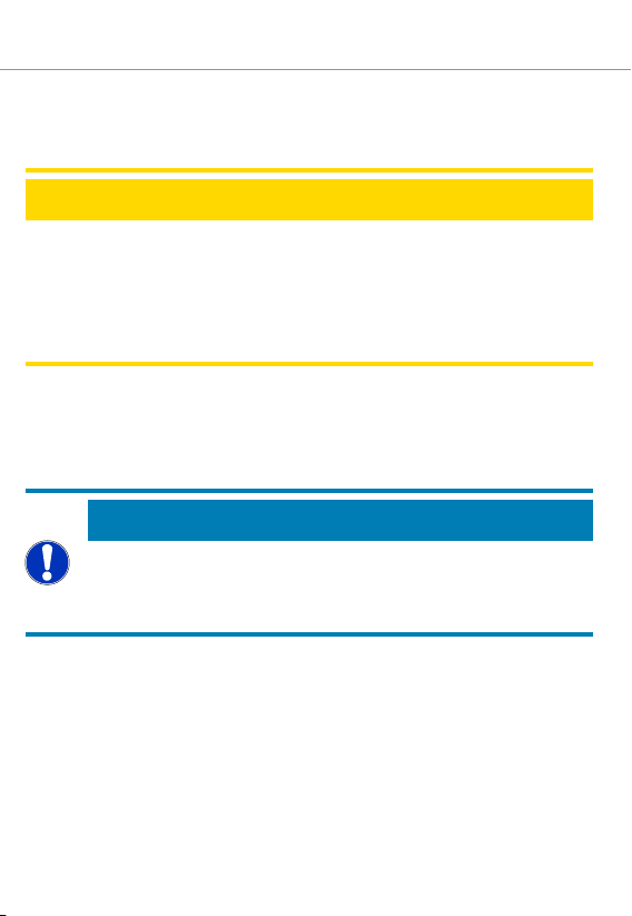
4. Griffmuldenring nach hinten Richtung Vorhangschloss schieben, so
dass er sich vom Knauf löst.
5. Griffmuldenring festhalten, Knauf ca. 10° gegen den Uhrzeigersinn
drehen und abziehen.
6. Beide Batterien vorsichtig aus der Halterung ziehen.
7. Die neuen Batterien mit den Pluspolen zueinander gleichzeitig in
die Halterung schieben (Batterien bitte zügig wechseln). Die neuen
Batterien nur mit sauberen und fettfreien Handschuhen berühren.
8. Knauf wieder aufstecken (entsprechend der dreieckigen Markierungen, siehe Skizze) und im Uhrzeigersinn drehend (ca. 10°) befestigen.
9. Griffmuldenring wieder auf den Knauf schieben, so dass Knauf und
Ring bündig abschließen.
10. Den Batterie-/Montageschlüssel am Knauf so ansetzen, dass die
beiden Nasen in die Öffnungen der Rastscheibe eingreifen. (Bei
Bedarf Knauf drehen bis beide Nasen des Schlüssels in den Knauf
einhaken.)
11. Knauf durch eine Drehung um ca. 30° gegen den Uhrzeigersinn
wieder verschließen (bis Sie ein Knacken vernehmen).
11
Page 12

Griffmuldenring
Innenknauf
Batterien
Markierungen
12
6 | Batteriewechsel Aktiv-Version
Page 13

7 | Batteriewechsel (Passiv) SC-Version
7 Batteriewechsel (Passiv) SC-Version
1. Den Batterie-/Montageschlüssel am Knauf so ansetzen, dass die
beiden Nasen in die Öffnungen der Rastscheibe eingreifen. (Bei
Bedarf Knauf drehen, bis beide Nasen des Schlüssels in den Knauf
einhaken.) Achtung: Damit der Batterie-/Montageschlüssel in die
Rastscheibe eingreifen kann, muss dieser plan an der Innenstirnfläche des Griffmuldenrings anliegen.
2. Knauf festhalten und Batterie-/Montageschlüssel vorsichtig ca. um
30° im Uhrzeigersinn drehen (bis Sie ein Knacken vernehmen).
3. Batterie-/Montageschlüssel vom Knauf entfernen.
4. Griffmuldenring nach hinten Richtung Vorhangschloss schieben, so
dass er sich vom Knauf löst.
5. Griffmuldenring festhalten, und Knauf ca. 10° gegen den Uhrzeigersinn drehen und abziehen.
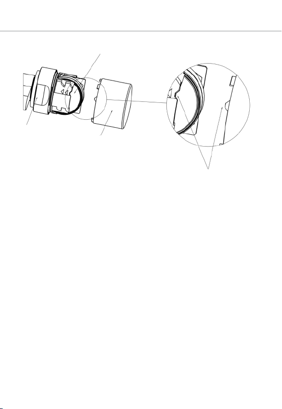
6. Vorsichtig die Batteriehalterung zusammendrücken (dort, wo die
drei kleinen Pfeile zu erkennen sind), damit sich die Antennenhalterung entrastet.
7. Die Antennenhalterung vorsichtig wegklappen (Siehe Abbildung),
diese aber nicht mechanisch belasten.
8. Optional: Falls eine Netzwerkplatine verbaut wurde, diese vorsichtig aus der Halterung ziehen.
9. Die obere Batterie aus der Halterung ziehen.
10. Um die zweite Batterie entfernen zu können, den Knauf um 180°
drehen. Die Batterie fällt dann automatisch aus der Halterung.
11. Die neuen Batterien mit den Pluspolen zueinander gleichzeitig in
die Halterung schieben (Batterien bitte zügig wechseln). Die neuen
Batterien nur mit sauberen und fettfreien Handschuhen berühren.
12. Die Antennenhalterung wieder verrasten. Hierbei darauf achten,
dass beide Seiten fest eingerastet sind.
13. Knaufkappe wieder aufstecken (entsprechend den drei dreieckigen
Markierungen, siehe Skizze) und im Uhrzeigersinn drehend (ca.
10°) befestigen (siehe Abbildung).
14. Griffmuldenring wieder auf den Knauf schieben, so dass Knauf und
Ring bündig abschließen.
13
Page 14
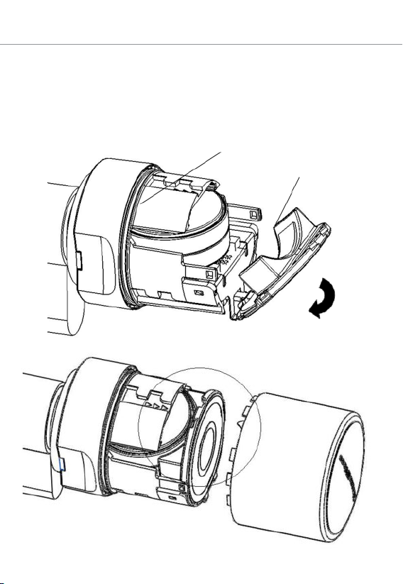
Batteriehalterung
Antennenhalterung
14
7 | Batteriewechsel (Passiv) SC-Version
15. Den Batterie-/Montageschlüssel am Knauf so ansetzen, dass die
beiden Nasen in die Öffnungen der Rastscheibe eingreifen (bei Bedarf Knauf drehen bis beide Nasen des Schlüssels in den Knauf
einhaken).
16. Knauf durch eine Drehung um ca. 30° gegen den Uhrzeigersinn
wieder verschließen (bis Sie ein Knacken vernehmen).
Page 15
8 | Hilfe & Kontakt
8 Hilfe & Kontakt
Infomaterial/Dokumente
Detaillierte Informationen zum Betrieb und zur Konfiguration, (EU-/
EG-)Konformitätserklärungen und weitere Dokumente finden Sie auf der
SimonsVoss-Homepage (www.simons-voss.com) im Supportbereich unter Infomaterial/Dokumente.
Konformitätserklärung
Hiermit erklärt SimonsVoss Technologies GmbH, dass das Funkübertragungsgerät PadLock die Anforderungen der Richtlinie 2014/53/EU erfüllt.
Eine vollständige Konformitätserklärung finden Sie unter der folgenden
Adresse: https://www.simons-voss.com/de/zertifikate.html.
Informationen zur Entsorgung
– Entsorgen Sie das Gerät (PadLock) nicht mit dem Hausmüll, son-
dern gemäß der europäischen Richtlinie 2012/19/EU bei einer kommunalen Sammelstelle für Elektro-Sonderabfälle.
– Recyceln Sie defekte oder verbrauchte Batterien gemäß der euro-
päischen Richtlinie 2006/66/EG.
– Beachten Sie örtliche Bestimmungen zur getrennten Entsorgung
von Batterien.
– Führen Sie die Verpackung einer umweltgerechten Wiederverwer-
tung zu.
15
Hotline
Bei technischen Fragen hilft Ihnen die SimonsVoss Service-Hotline unter
+49 (0) 89 99 228 333 (Anruf in das deutsche Festnetz, Kosten variieren
je nach Anbieter).
E-Mail
Sie möchten uns lieber eine E-Mail schreiben?
support@simons-voss.com
Page 16

16
FAQ
Informationen und Hilfestellungen zu SimonsVoss-Produkten finden Sie
auf der SimonsVoss-Homepage (www.simons-voss.com) im Supportbereich unter FAQ.
SimonsVoss Technologies GmbH
Feringastraße 4
85774 Unterföhring
Deutschland
8 | Hilfe & Kontakt
Page 17

Content
1 General information ........................................................................... 18
2 Safety instructions............................................................................. 19
3 Operating the SL version................................................................... 21
4 Operating the ML version.................................................................. 22
5 Audible signals................................................................................... 23
6 Battery warnings for active version ................................................. 25
7 Battery replacement (Passive) SC version ...................................... 27
8 Help & Contact.................................................................................... 29
Page 18

18
1 General information
– When installing the digital padlock, ensure that there are no
sources of interference in the surrounding area. (Active) padlocks
should be installed at least 0.5 m from one another while (active)
SmartRelays or (active) activation units should be 1.5 m from one
another.
– You must not strike the thumb-turn during installation.
– The thumb-turn is locked into place with a bayonet mount.
– The padlock is supplied ready for installation.
– Programme padlocks before installing. Padlocks are supplied from
the factory in ‘storage mode’ and cannot be activated with a
transponder before initial programming.
Important: Batteries are already installed before delivery.
1 | General information
Page 19

2 | Safety instructions
2 Safety instructions
Warning:
– Access through a door may be blocked due to incorrectly installed
or incorrectly programmed padlocks. SimonsVoss Technologies
GmbH is not liable for consequences of incorrect installation, such
as denied access to injured persons, physical damage or any other
losses.
– The batteries used in the digital padlock may pose a fire or burn
hazard if handled incorrectly. Do not recharge, open, heat or burn
these batteries. Do not short-circuit batteries.
Important:
– SimonsVoss Technologies GmbH accepts no liability for damage
caused to doors or components due to incorrect fitting or installation.
– The SimonsVoss padlock may only be used for its intended pur-
pose. No other use is permitted.
– Only trained specialists may install the cylinder.
– Do not allow padlocks to come into contact with oil, paint or acids.
– We reserve the right to make modifications or further technical de-
velopments.
– This documentation has been compiled based on the best know-
ledge available to us. However, errors cannot be ruled out. No liab-
ility is accepted in such cases.
– Should there be differences in the content of other language ver-
sions of this documentation, the German version applies in cases of
doubt.
Instructions on battery replacement
– Only trained specialists may replace the battery.
– Damage may be caused to the cylinder electronics if you reverse
the polarity.
– Only use batteries which have been approved by SimonsVoss.
– The padlock must always be operated with two batteries.
– Dispose of old and used batteries in the proper manner and store
them out of children's reach.
– Always replace both batteries when changing batteries.
19
Page 20

20
2 | Safety instructions
– Do not touch the contacts on the new batteries with your hands
when replacing the old ones. Use clean gloves free of fat or grease
to handle the battery.
– When replacing the batteries, make sure that the electronics are
not subject to mechanical load and are not damaged in any other
way.
– Only use the SimonsVoss installation/battery key
(Z4.SCHLUESSEL) to replace the battery.
Page 21

3 | Operating the SL version
3 Operating the SL version
Opening
– Active: Activate the transponder within the thumb-turn’s communic-
ation range or
– (Passive) SC: Hold the smart card or smart tag in front of the
reader thumb-turn.
– You can open the padlock by turning the thumb-turn about 30° in a
clockwise direction until it will go no further and the shackle opens.
Locking
– Close shackle; the shackle always locks into place automatically.
– Always check that it has locked properly.
21
Page 22

22
4 Operating the ML version
Opening
– Active: Activate the transponder within the thumb-turn’s communic-
ation range or
– (Passive) SC: Hold the smart card or smart tag in front of the
reader thumb-turn.
– You can open the padlock by turning the thumb-turn about 30° in a
clockwise direction until it will go no further and the shackle opens.
Locking
– Close shackle.
– Active: Activate the transponder within the thumb-turn’s communic-
ation range or
– (Passive) SC: Hold the smart card in front of the reader thumb-turn.
– You can open the padlock by turning the thumb-turn about 30° in
an anti-clockwise direction until it will go no further.
– Always check that it has locked properly.
4 | Operating the ML version
Page 23

5 | Audible signals
5 Audible signals
Active version
– 2 short audible signals before engaging and a short signal after dis-
engaging indicate normal operation.
– Battery Warning Level 1: 8 short audible signals before engaging.
Batteries will soon be empty. Replace batteries in the padlock.
– Battery Warning Level 2: 8 short audible signals for 30 seconds
with a one-second break between each signal. Indicates emergency battery warning: Batteries are almost completely empty. Replace batteries in the padlock immediately.
– 8 short audible signals after disengaging indicate that the transpon-
der battery is empty. Have transponder battery replaced
(Passive) SC version
– 2 short audible signals + LED flashes blue twice briefly before en-
gaging and a short audible signal after disengaging: indicates normal activation.
– Battery Warning Level 1: 8 short audible signals + LED flashing red
briefly 8x before engaging. Batteries will soon be empty. Replace
batteries in the padlock.
– Battery Warning Level 2: 8 short audible signals for 30 seconds +
LED flashes red briefly twice with a one-second break between
each signal. Indicates emergency battery warning: Batteries are almost completely empty. Replace batteries in the padlock immediately.
– 8 short audible signals after disengaging indicate that the transpon-
der battery is empty. Have transponder battery replaced.
After Battery Warning Level 2 is emitted for the first time, it is still possible
– Active padlock: about 50 opening transactions are carried out.
– (Passive) padlock: about 200 opening transactions are carried out.
After reaching this number of opening transactions or after about 4
weeks (active) / about 2 weeks (passive/SC), the padlock automatically
switches to
– G1: emergency battery storage mode
– G2: freeze mode
23
Page 24

24
Once this warning level is reached, only the locking system administrator
is able to gain access. User transponders are no longer accepted (consult 'Battery warnings' in the locking cylinder manual for more detailed information).
5 | Audible signals
Page 25

6 | Battery warnings for active version
6 Battery warnings for active version
1. Place the installation/battery key on the knob in such a way that its
two teeth lock into the openings in the locking disc; If necessary,
turn the knob until both teeth engage into the knob. Important: the
battery/installation key must be placed flat on the inside front surface of the recessed grip ring to ensure that the installation tool can
engage into the locking disc.
2. Hold the knob firmly and carefully turn the battery/installation key
about 30° in a clockwise direction (until you hear a click).
3. Remove battery/installation key from the knob.
4. Push recessed grip ring backwards towards the padlock, so that it
comes away from the thumb-turn.
5. Hold recessed grip ring, turn knob about 10° in an anti-clockwise
direction and remove.
6. Carefully remove both batteries from the holder.
7. Insert the new batteries into the holder at the same time with the
positive poles next to each other; change the batteries as quickly as
possible. Use clean gloves free of fat or grease to handle new batteries.
8. Replace the knob (align the triangle marks as in the diagram) and
turn about 10° in a clockwise direction.
9. Push recessed grip ring back onto the knob, so that the knob and
ring close together in a flush fit.
10. Place the installation/battery key on the knob in such a way that its
two teeth lock into the openings in the locking disc; If necessary,
turn the knob until both teeth engage into the knob.
11. Lock the knob into place again by turning it about 30° in an anticlockwise direction (until you hear a click).
25
Page 26

Recessed grip ring
Inside Knob
Batteries
Markings
26
6 | Battery warnings for active version
Page 27

7 | Battery replacement (Passive) SC version
7 Battery replacement (Passive) SC version
1. Place the installation/battery key on the knob in such a way that its
two teeth lock into the openings in the locking disc; If necessary,
turn the knob until both teeth engage into the knob. Important: the
battery/installation key must be placed flat on the inside front surface of the recessed grip ring to ensure that the installation tool can
engage into the locking disc.
2. Hold the knob firmly and carefully turn the battery/installation key
about 30° in a clockwise direction (until you hear a click).
3. Remove battery/installation key from the knob.
4. Push recessed grip ring backwards towards the padlock, so that it
comes away from the thumb-turn.
5. Hold recessed grip ring firmly and turn knob about 10° in an anticlockwise direction and remove.
6. Carefully press the battery holder together where you see three
small arrows, so that the antenna bracket disengages.
7. Carefully fold the antenna bracket out (see diagram); do not apply
any mechanical load to it.
8. Optional: If a network card has been fitted, carefully remove it from
the holder.
9. Remove the top battery from the holder.
10. Turn the knob 180°, so that you can remove the second battery.
The battery will then automatically drop from the holder.
11. Insert the new batteries into the holder at the same time with the
positive poles next to each other; change the batteries as quickly as
possible. Use clean gloves free of fat or grease to handle new batteries.
12. Carefully lock the antenna bracket back into place. In doing so, ensure that both sides lock firmly into place.
13. Replace the thumb-turn (align the three triangle marks as in the diagram) and turn about 10° in a clockwise direction (see diagram).
14. Push recessed grip ring back onto the knob, so that the knob and
ring close together in a flush fit.
15. Place the battery/installation key on the knob in such a way that its
two teeth lock into the openings in the locking disc; if necessary,
turn the knob until both teeth engage into the knob.
27
Page 28
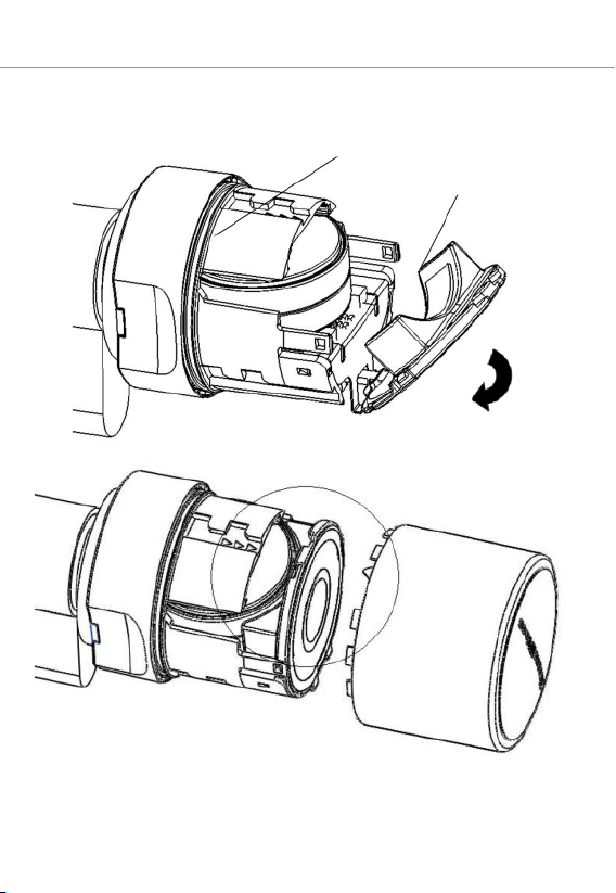
Battery holder
Antenna bracket
28
7 | Battery replacement (Passive) SC version
16. Lock the knob into place again by turning it about 30° in an anticlockwise direction (until you hear a click).
Page 29

8 | Help & Contact
8 Help & Contact
Information material/documents
You will find detailed information on operating and configuration, (EU)
declarations of conformity and other documents under Informative Material/Documents in the Support section on the SimonsVoss website at
(www.simons-voss.com).
Declaration of conformity
SimonsVoss Technologies GmbH hereby declares that the radio transmission device PadLock complies with the requirements stipulated in Directive 2014/53/EU.
You will find a complete declaration of conformity at: https://www.si-
mons-voss.com/en/certificates.html.
Information on disposal
– Do not dispose the device (PadLock) in the household waste. Dis-
pose of it at a collection point for electronic waste as per European
Directive 2012/19/EU.
– Recycle defective or used batteries in line with European Directive
2006/66/EC.
– Observe local regulations on separate disposal of batteries.
– Take the packaging to an environmentally responsible recycling
point.
29
Hotline
If you have any questions, the SimonsVoss Service Hotline will be happy
to help you on +49 (0)89 99 228 333 (German fixed network; call
charges vary depending on the operator).
Email
You may prefer to send us an email.
support@simons-voss.com
Page 30

30
FAQs
You will find information and help for SimonsVoss products under FAQ in
the Support section on the SimonsVoss website (www.simonsvoss.com).
SimonsVoss Technologies GmbH
Feringastrasse 4
85774 Unterföhring
Germany
8 | Help & Contact
Page 31

1 Généralités.......................................................................................... 32
2 Précautions de sécurité..................................................................... 33
3 Manipulation version SL.................................................................... 35
4 Manipulation version SL.................................................................... 36
5 Bips...................................................................................................... 37
6 Changement des piles version active .............................................. 39
7 Remplacement des piles version SC (passive)............................... 41
8 Aide & Contact.................................................................................... 43
Page 32

32
1 Généralités
– Lors de l’installation cadenas numérique, veiller à ce qu’aucune
source de perturbation ne se trouve à proximité. Les cadenas (actifs) doivent être montés à une distance minimum de 0,5m les uns
des autres, et le Smart Relais (actif) et respectivement l'unité de
distribution (active) à au moins 1,5 m.
– Lors du montage, veiller à ne surtout pas heurter le bouton de
porte.
– Le bouton de porte est verrouillé par une fermeture à baïonnette.
– Le cadenas est fourni prêt à être installé.
– Programmer le cadenas avant le montage! Les cadenas sont livrés
à partir de l'usine en « mode par défaut » et ne peuvent pas être
activés par transpondeur avant la programmation initiale !
Remarque: à la livraison, les piles sont déjà installées !
1 | Généralités
Page 33

2 | Précautions de sécurité
2 Précautions de sécurité
Attention:
– un cadenas mal installé ou mal programmé peut bloquer un accès
au niveau d’une porte. SimonsVoss Technologies GmbH décline
toute responsabilité pour les conséquences d’installations impropres, comme l’accès impossible à des personnes blessées, les
dommages matériels ou d’autres dommages.
– En cas de manipulation impropre, les piles insérées dans le cade-
nas numérique peuvent provoquer un incendie ou des brûlures. Ne
pas recharger, ouvrir, chauffer ou brûler ces piles! Ne pas courtcircuiter les piles!
Remarques:
– SimonsVoss Technologies GmbH décline toute responsabilité pour
les dommages causés aux portes ou aux composants en raison
d'une installation impropre.
– Le cadenas SimonsVoss doit uniquement être utilisé conformément
à sa destination. Toute autre utilisation est interdite.
– L’installation ne doit être effectuée par du personnel qualifié!
– Ne pas laisser les cadenas au contact de l'huile, de peintures ou
d'acides.
– Sous réserve de modifications et de nouveaux développements
techniques.
– Cette documentation a été rédigée avec soin, celle-ci peut toutefois
comporter des erreurs éventuelles. Notre responsabilité ne peut sur
ce point, pas être engagée.
– Si le contenu de la documentation devait varier en fonction des ver-
sions en langues étrangères, alors la version originale en allemand
reste la seule pertinente en cas de doutes.
Remarques relatives au remplacement des piles
– Le remplacement des piles doit être effectué par du personnel qua-
lifié!
– L'inversion de la polarité peut endommager l’électronique du cy-
lindre!
– Seules les piles préconisées par SimonsVoss doivent être utilisées.
– Le cadenas fonctionne avec deux piles !
33
Page 34

34
2 | Précautions de sécurité
– Éliminer les piles anciennes ou usées en respectant la réglementa-
tion en vigueur et conserver les hors de la portée des enfants !
– Lors du changement de piles, veiller à toujours remplacer les deux
piles en même temps !
– Lors du remplacement des piles, veiller à ne pas toucher les
contacts des nouvelles piles avec les mains. Utiliser pour cela des
gants propres et non graisseux.
– Lors du remplacement des piles, s'assurer que l'électronique ne
soit pas soumis à des pressions mécaniques ou l'objet de dommages.
– Lors du remplacement des piles utiliser impérativement la clé de
montage/clé de piles (Z4.SCHLÜSSEL) de SimonsVoss.
Page 35

3 | Manipulation version SL
3 Manipulation version SL
Ouverture
– Actif : actionner le transpondeur à portée de communication du
bouton ou
– SC (passif): Tenir la SmartCard ou le SmartTag devant le bouton
de lecture.
– Tourner le bouton en butée à env. 30° dans le sens des aiguilles
d'une montre (jusqu'à ce qu'une résistance soit perceptible) pour
ouvrir l'étrier.
Fermeture
– Fermer l'anse, cette dernière se verrouille automatiquement.
– Toujours vérifier que la fermeture a été effectuée correctement.
35
Page 36

36
4 Manipulation version SL
Ouverture
– Actif : actionner le transpondeur à portée de communication du
bouton ou
– SC (passif): Tenir la SmartCard ou le SmartTag devant le bouton
de lecture.
– Tourner le bouton en butée à env. 30° dans le sens des aiguilles
d'une montre (jusqu'à ce qu'une résistance soit perceptible) pour
ouvrir l'étrier.
Fermeture
– fermer l'anneau.
– Actif : actionner le transpondeur à portée de communication du
bouton ou
– SC (passif): tenir la SmartCard devant le bouton de lecture.
– Tourner le bouton en butée à env. 30° dans le sens inverse des ai-
guilles d'une montre (jusqu'à ce qu'une résistance soit perceptible).
– Toujours vérifier que la fermeture a été effectuée correctement.
4 | Manipulation version SL
Page 37

5 | Bips
5 Bips
Version active
– 2 bips courts avant le couplage et 1 bip court après le découplage :
actionnement normal.
– Niveau d'alerte des piles 1 : 8 signaux sonores courts avant le cou-
plage. Piles bientôt entièrement déchargées. Changer les piles du
cadenas.
– Niveau d'alerte des piles 2 : huit signaux sonores émis durant 30
secondes avec une seconde de pause. Alerte de la pile de secours : piles extrêmement déchargées. Remplacer immédiatement
les piles du cadenas !
– 8 signaux sonores après le découplage signifient que la pile du
transpondeur est déchargée. Remplacer la pile du transpondeur
Version SC (passive)
– 2 signaux sonores courts et diode DEL clignote 2x en bleu avant le
couplage et 1 signal sonore court après le découplage : actionnement normal.
– Niveau d'alerte des piles 1 : 8 signaux sonores courts + la diode
DEL clignote 8x brièvement rouge avant le couplage. Piles bientôt
entièrement déchargées. Changer les piles du cadenas.
– Niveau d'alerte des piles 2 : huit signaux sonores brefs émis durant
30 secondes + diode LED clignote brièvement 2x rouge avec une
seconde de pause. Alerte de la pile de secours : piles extrêmement
déchargées. Remplacer immédiatement les piles du cadenas !
– 8 signaux sonores après le découplage signifient que la pile du
transpondeur est déchargée. Laisser changer la pile du transpondeur
Lorsque le niveau d'alerte des piles 2 retentit pour la première fois, il est
encore possible
– Cadenas actif: env. 50 ouvertures peuvent être effectuées.
– Cadenas SC (passif): env. 200 ouvertures peuvent être effectuées.
Une fois ce nombre d'ouvertures passé, soit env. au bout de 4semaines
(active) / 2semaines (passif/SC), le cadenas passe automatiquement en
– G1 : mode pile de secours
– G2: mode Freeze (mode veille)
37
Page 38

38
À partir de ce niveau d'alerte, seul l'administrateur de l'installation de fermeture a la possibilité d'entrer. Les transpondeurs d'utilisateurs ne seront plus acceptés (pour plus d'informations, voir le Manuel des cylindres
de fermeture sous «Alertes des piles»).
5 | Bips
Page 39

6 | Changement des piles version active
6 Changement des piles version active
1. Positionner l’outil de montage/la clé de remplacement des piles sur
le bouton de telle sorte que les deux becs rentrent dans les ouvertures du disque d’arrêt (En cas de besoin tourner le bouton de
porte jusqu’à ce que les deux becs de la clé s’accrochent dans le
bouton.) Attention: afin que la clé de montage/ de remplacement
des piles puisse accéder au disque d’arrêt, il faut qu’elle soit à plat
sur le front intérieur de la bague.
2. Maintenir le bouton et tourner avec précaution la clé de montage/
de remplacement des piles d’environ 30° dans le sens des aiguilles
d’une montre (jusqu’à entendre un clic).
3. Retirer du bouton de porte la clé de montage/ de remplacement
des piles.
4. Pousser la bague vers l'arrière en direction du cadenas afin qu'elle
se détache du bouton de porte.
5. Tenir la bague, puis tourner le bouton de porte d’env. 10° dans le
sens inverse des aiguilles d’une montre et le retirer.
6. Retirer délicatement les deux piles de leur support.
7. Insérer les piles neuves en même temps dans l’emplacement prévu
à cet effet, les pôles plus en face l’un de l’autre (remplacer les piles
le plus rapidement possible). Ne toucher les nouvelles piles
qu'avec des gants propres et non graisseux.
8. Remettre en place le bouton de porte (en fonction des repères triangulaires, cf. schéma) et le fixer en tournant dans le sens des aiguilles d'une montre (sur env. 10°).
9. Remettre la bague sur le bouton de porte de façon à ce que bouton
et bague ne fassent qu’un.
10. Positionner l’outil de montage/la clé de remplacement des piles sur
le bouton de telle sorte que les deux becs rentrent dans les ouvertures du disque d’arrêt (En cas de besoin tourner le bouton de
porte jusqu’à ce que les deux becs de la clé s’accrochent dans le
bouton.)
11. Refermer le bouton de porte en tournant d’env. 30° dans le sens inverse des aiguilles d’une montre (jusqu’à entendre un clic).
39
Page 40

Bague
Bouton de porte intérieur
Piles
Marquages
40
6 | Changement des piles version active
Page 41

7 | Remplacement des piles version SC (passive)
7 Remplacement des piles version SC (passive)
1. Positionner l’outil de montage/la clé de remplacement des piles sur
le bouton de telle sorte que les deux becs rentrent dans les ouvertures du disque d’arrêt (En cas de besoin tourner le bouton de
porte jusqu’à ce que les deux becs de la clé s’accrochent dans le
bouton.) Attention: afin que la clé de montage/ de remplacement
des piles puisse accéder au disque d’arrêt, il faut qu’elle soit à plat
sur le front intérieur de la bague.
2. Maintenir le bouton et tourner avec précaution la clé de montage/
de remplacement des piles d’environ 30° dans le sens des aiguilles
d’une montre (jusqu’à entendre un clic).
3. Retirer du bouton de porte la clé de montage/ de remplacement
des piles.
4. Pousser la bague vers l'arrière en direction du cadenas afin qu'elle
se détache du bouton de porte.
5. Tenir la bague, puis tourner le bouton de porte d’env. 10° dans le
sens inverse des aiguilles d’une montre et le retirer.
6. Presser délicatement le support des piles (là où se trouvent les
trois petites flèches) afin que le support de l'antenne se débloque.
7. Replier délicatement le support de l'antenne (cf. figure) sans toutefois exercer de contrainte mécanique sur celle-ci.
8. En option: Si une platine de réseau a été installée, il faut la retirer
délicatement du support.
9. Retirer la pile du haut de son support.
10. Pour pouvoir retirer la deuxième pile, tourner le bouton de porte à
180°. La pile tombe alors automatiquement du support.
11. Insérer les piles neuves en même temps dans l’emplacement prévu
à cet effet, les pôles plus en face l’un de l’autre (remplacer les piles
le plus rapidement possible). Ne toucher les nouvelles piles
qu'avec des gants propres et non graisseux.
12. Remettre en place le support de l'antenne. Veiller pour ce faire à ce
que les deux côtés soient bien enclenchés.
13. Remettre en place le cache du bouton (en fonction des trois repères triangulaires, cf. schéma) et le fixer en tournant (sur env. 10°)
dans le sens des aiguilles d'une montre (cf. figure).
14. Remettre la bague sur le bouton de porte de façon à ce que bouton
et bague ne fassent qu’un.
41
Page 42

Support de pile
Support de l'antenne
42
7 | Remplacement des piles version SC (passive)
15. Positionner la clé de montage/ de remplacement des piles sur le
bouton de telle sorte que les deux becs rentrent dans les ouvertures du disque d’arrêt (au besoin, tourner le bouton de porte jusqu’à ce que les deux becs de la clé s’accrochent dans le bouton).
16. Refermer le bouton de porte en tournant d’env. 30° dans le sens inverse des aiguilles d’une montre (jusqu’à entendre un clic).
Page 43

8 | Aide & Contact
8 Aide & Contact
Documentation/documents
Les informations détaillées concernant le fonctionnement et la configuration, les déclarations de conformité (UE/CE) ainsi que d’autres documents peuvent être consultés sur la page d'accueil de SimonsVoss
(www.simons-voss.com) dans la section Assistance sous Documentation/Documents.
Déclaration de conformité
Par la présente, SimonsVoss Technologies GmbH certifie que l’appareil
de transmission radio PadLock répond aux attentes de la Directive
2014/53/UE.
Vous pouvez consulter la déclaration de conformité dans sa totalité à
l’adresse suivante: https://www.simons-voss.com/fr/certificats.html.
Informations sur l'elimination
– Ne jetez pas l’appareil (PadLock) avec vos ordures ménagères
mais dans un point de collecte communal pour appareils électriques et appareils spéciaux conformément à la directive européenne 2012/19/UE.
– Recyclez les piles défectueuses ou usées conformément à la direc-
tive européenne 2006/66/CE.
– Veuillez tenir compte des dispositions locales applicables concer-
nant la collecte séparée des piles.
– Recyclez l’emballage d’une manière écologique.
43
Hotline
En cas de questions techniques, contactez la Hotline SimonsVoss au
+49 (0) 89 99 228 333 (appel vers le réseau fixe allemand, coût variable
en fonction de l'opérateur).
E-mail
Vous préférez nous envoyer un e-mail?
Page 44

44
support@simons-voss.com
FAQ
Les informations et aides relatives aux produits SimonsVoss peuvent
être consultées sur la page d'accueil de SimonsVoss (www.simonsvoss.com) dans la section Assistance sous FAQ.
SimonsVoss Technologies GmbH
Feringastrasse 4
85774 Unterföhring
Allemagne
8 | Aide & Contact
Page 45

Inhoudsopgave
1 Algemeen ............................................................................................ 46
2 Veiligheidsaanwijzingen.................................................................... 47
3 Bediening SL-uitvoering.................................................................... 49
4 Bediening ML-uitvoering ................................................................... 50
5 Akoestische signalen ........................................................................ 51
6 Batterijvervanging actief-versie........................................................ 53
7 Batterijvervanging (passief) SC-versie ............................................ 55
8 Hulp & contact.................................................................................... 57
Page 46

46
1 Algemeen
– Bij de installatie van het digitale hangslot moet erop gelet worden
dat zich geen storingsbronnen in de directe omgeving bevinden.
(Actieve) hangsloten moeten ten minste op een afstand van 0,5 m
uit elkaar worden aangebracht, (actieve) SmartRelais, resp. (actieve) scherpschakeleenheden op een afstand van 1,5 m.
– Bij de montage mag nooit op de knop worden geslagen.
– De knop is gesloten met een bajonetsluiting.
– Het hangslot wordt klaar voor montage geleverd.
– Het hangslot voorafgaand aan de montage programmeren! De
hangsloten worden af fabriek in de "opslagmodus" geleverd en kunnen voor de eerste programmering niet geactiveerd worden met
een transponder.
Tip: Bij levering zijn de batterijen reeds aangebracht!
1 | Algemeen
Page 47

2 | Veiligheidsaanwijzingen
2 Veiligheidsaanwijzingen
Let op!
– Door foutief geïnstalleerde of geprogrammeerde hangsloten kan de
doorgang door een deur geblokkeerd zijn. Voor de gevolgen van
verkeerde installatie, zoals geen toegang tot gewonden, materiële
of andere schade is SimonsVoss Technologies BV niet aansprakelijk.
– De batterijen die in het digitale hangslot worden gebruikt, kunnen
bij verkeerde behandeling tot brand- of verbrandingsgevaar leiden.
Deze batterijen mogen niet worden opgeladen, geopend, verhit of
verbrand! Batterijen niet kortsluiten.
Aanwijzingen:
– Voor beschadiging van deuren of componenten als gevolg van ver-
keerde montage aanvaardt SimonsVoss Technologies BV geen
aansprakelijkheid.
– Het SimonsVoss hangslot mag alleen voor het beoogde gebruik
worden ingezet. Een andersoortig gebruik is niet toegestaan.
– De montage mag alleen worden uitgevoerd door deskundigen!
– Hangsloten niet in aanraking brengen met olie, verf, zuren, e.d.
– Onder voorbehoud van aanpassingen of technische innovaties.
– De documentatie werd te goeder trouw vervaardigd. Eventuele fou-
ten kunnen niettemin niet worden uitgesloten. Voor dergelijke fou-
ten wordt geen aansprakelijkheid aanvaard.
– Indien afwijkingen van de inhoud in vertaalde versies van de docu-
mentatie optreden, geldt in geval van twijfel de tekst van het Duitse
origineel.
Aanwijzingen voor de vervanging van batterijen
– De batterijen mogen alleen worden vervangen door deskundigen!
– Verwisseling van de polariteit kan leiden tot beschadiging van de
elektronica van de cilinder!
– Er mogen uitsluitend batterijen worden gebruikt die SimonsVoss
heeft vrijgegeven!
– Het hangslot moet bediend worden met twee batterijen.
47
Page 48

48
2 | Veiligheidsaanwijzingen
– Oude en verbruikte batterijen moeten op de juiste manier als afval
worden behandeld en mogen niet binnen bereik van kinderen wor-
den bewaard.
– Bij vervanging van de batterijen altijd beide batterijen vervangen!
– Bij een vervanging van de batterijen mogen de contacten van de
nieuwe batterijen niet met de handen worden aangeraakt. Gebruik
hiervoor schone, vetvrije handschoenen.
– Bij vervanging van de batterijen moet er op gelet worden dat de
elektronica niet mechanisch wordt belast of op een andere manier
wordt beschadigd.
– Voor het vervangen van batterijen uitsluitend de montage-/batterij-
sleutel (Z4.SLEUTEL) van SimonsVoss gebruiken.
Page 49

3 | Bediening SL-uitvoering
3 Bediening SL-uitvoering
Opening
– Actief: de transponder binnen het communicatiebereik van de knop
activeren, of
– (passief) SC: de SmartCard of de SmartTag voor de knop met de
lezer houden.
– Knop ca. 30° in de richting van de klok tot aan de aanslag draaien
(tot een weerstand merkbaar is) en de beugel openen.
Sluiting
– Beugel dichtmaken en automatisch laten inrasten.
– Goed controleren of het slot correct gesloten is.
49
Page 50

50
4 Bediening ML-uitvoering
Opening
– Actief: de transponder binnen het communicatiebereik van de knop
activeren, of
– (passief) SC: de SmartCard of de SmartTag voor de knop met de
lezer houden.
– Knop ca. 30° in de richting van de klok tot aan de aanslag draaien
(tot een weerstand merkbaar is) en de beugel openen.
Sluiting
– beugel sluiten.
– Actief: de transponder binnen het communicatiebereik van de knop
activeren, of
– (passief) SC: de SmartCard voor de knop met de lezer houden.
– Knop ca. 30° tegen de richting van de klok tot aan de aanslag
draaien (tot een weerstand merkbaar is).
– Goed controleren of het slot correct gesloten is.
4 | Bediening ML-uitvoering
Page 51

5 | Akoestische signalen
5 Akoestische signalen
Actieve versie
– 2 korte signalen voor het vrijschakelen en een kort signaal na het
uitschakelen geven normaal gebruik aan.
– Batterij-alarm stap 1: 8 korte signalen voor het vrijschakelen. Batte-
rijen zijn binnenkort leeg. Batterijen in het voorhangslot vervangen.
– Batterij-alarm stap 2: 30 seconden lang 8 korte signalen met tel-
kens een seconde pauze. Geeft een noodbatterij-alarm aan: Batterijen zijn extreem leeg. Meteen de batterijen in het hangslot vervangen!
– 8 korte signalen na het uitschakelen geven aan dat de transponder-
batterij leeg is. Transponderbatterij laten vervangen
(Passief) SC-versie
– 2 korte signalen + 2x kort blauw knipperen van de LED voor het
vrijschakelen en een kort signaal na het uitschakelen: geeft normaal gebruik aan.
– Batterij-alarm stap 1: 8 korte signalen + LED knippert 8x kort rood
voor het vrijschakelen. Batterijen zijn binnenkort leeg. Batterijen in
het voorhangslot vervangen.
– Batterij-alarm stap 2: 30 seconden lang 8 korte signalen + LED
knippert telkens 2x kort rood met elke keer een seconde pauze:
Geeft een noodbatterij-alarm aan: Batterijen zijn extreem leeg. Meteen de batterijen in het hangslot vervangen!
– 8 korte signalen na het uitschakelen geven aan dat de transponder-
batterij leeg is. Transponderbatterij laten vervangen.
Nadat het batterij-alarm stap 2 voor het eerst is gegeven, kunnen nog
– Actief hangslot: ca. 50 activeringen worden uitgevoerd
– (Passief) SC-hangslot: ca. 200 activeringen worden uitgevoerd.
Na het bereiken van dit aantal activeringen, resp. na ca. 4 weken (actief) / ca. 2 weken (passief/SC) gaat het hangslot automatisch over in de
– G1: Opslagmodus noodbatterij
– G2: Freezemodus
51
Page 52

52
5 | Akoestische signalen
Vanaf dit alarmniveau kan alleen nog de systeembeheerder van het sluitsysteem toegang krijgen. Transponders van gebruikers worden niet
meer geaccepteerd (zie ook het manual van de cilinder onder 'Batterijalarm").
Page 53

6 | Batterijvervanging actief-versie
6 Batterijvervanging actief-versie
1. Het batterijvervangings-/montagegereedschap dusdanig op de
knop zetten dat de twee neuzen in de openingen van de inrastschijf
grijpen. (Desgewenst de knop draaien tot de twee neuzen van de
sleutel in de schijf inrasten.) Let op: Om te zorgen dat de montage-/
batterijsleutel in de schrijf kan inrasten, moet deze vlak tegen het
front aan de binnenkant van de ring met inkepingen liggen.
2. Knop vasthouden en de montage-/batterijsleutel behoedzaam ca.
30° met de klok mee draaien (tot een knak is te horen).
3. Montage-/batterijsleutel van de knop nemen.
4. De ring met inkepingen naar achteren in de richting van het voorhangslot schuiven, zodat hij los komt van de knop.
5. De ring met inkepingen vasthouden en de knop 10° tegen de klok
in draaien en eraf trekken.
6. Beide batterijen voorzichtig uit de houder trekken.
7. De nieuwe batterijen met de pluspolen naar elkaar toe tegelijk in de
houder schuiven (batterijen zo snel mogelijk vervangen). De batterijen mogen alleen met schone, vetvrije handschoenen worden
aangeraakt.
8. De knop weer terug plaatsen (overeenkomstig de driehoekige markeringen, zie schets), de met de klok mee (ca 10°) vastdraaien.
9. De ring met inkepingen weer op de knop schuiven zodat de knop
en de ring met elkaar zijn uitgelijnd.
10. Het batterijvervangings-/montagegereedschap dusdanig op de
knop zetten dat de twee neuzen in de openingen van de inrastschijf
grijpen. (Indien nodig de knop draaien totdat de twee neuzen van
de sleutel in de knop inrasten.)
11. Knop door middel van een draai van ca. 30° tegen de klok in weer
sluiten (tot u een knak hoort).
53
Page 54
Ring met inkepingen
Binnenknop
Batterijen
Markeringen
54
6 | Batterijvervanging actief-versie
Page 55

7 | Batterijvervanging (passief) SC-versie
7 Batterijvervanging (passief) SC-versie
1. Het batterijvervangings-/montagegereedschap dusdanig op de
knop zetten dat de twee neuzen in de openingen van de inrastschijf
grijpen. (Indien nodig de knop draaien totdat de twee neuzen van
de sleutel in de knop inrasten.) Let op: Om te zorgen dat de montage-/batterijsleutel in de schrijf kan inrasten, moet deze vlak tegen
het front aan de binnenkant van de ring met inkepingen liggen.
2. Knop vasthouden en de montage-/batterijsleutel behoedzaam ca.
30° met de klok mee draaien (tot een knak is te horen).
3. Montage-/batterijsleutel van de knop nemen.
4. De ring met inkepingen naar achteren in de richting van het voorhangslot schuiven, zodat hij los komt van de knop.
5. De ring met inkepingen vasthouden en de knop 10° tegen de klok
in draaien en eraf trekken.
6. Voorzichtig de batterijhouder dichtdrukken (waar de drie kleine pijlen te zien zijn), zodat de antennehouder inrast.
7. De antennehouder voorzichtig opzij klappen (zie afbeelding) en niet
mechanisch belasten.
8. Optioneel: Wanneer een printplaat voor een netwerk is ingebouwd,
moet deze behoedzaam uit de houder getrokken worden.
9. De bovenste batterij uit de houder trekken.
10. Om de tweede batterij te kunnen verwijderen, moet de knop 180°
omgedraaid worden. De batterij valt dan vanzelf uit de houder.
11. De nieuwe batterijen met de pluspolen naar elkaar toe tegelijk in de
houder schuiven (batterijen zo snel mogelijk vervangen). De batterijen mogen alleen met schone, vetvrije handschoenen worden
aangeraakt.
12. De antennehouder weer laten inrasten. Hierbij opletten dat beide
zijden goed zijn ingerast.
13. De kap van de knop weer terug plaatsen (overeenkomstig de drie
driehoekige markeringen, zie schets) en met de klok mee (ca. 10°)
vastdraaien (zie afbeelding).
14. De ring met inkepingen weer op de knop schuiven zodat de knop
en de ring met elkaar zijn uitgelijnd.
55
Page 56

Batterijhouder
Antennehouder
56
7 | Batterijvervanging (passief) SC-versie
15. De montage-/batterijsleutel dusdanig aan de knop plaatsen dat de
twee neuzen in de openingen van de schijf inrasten (indien nodig
de knop draaien totdat de twee neuzen van de sleutel in de knop
inrasten).
16. Knop door middel van een draai van ca. 30° tegen de klok in weer
sluiten (tot u een knak hoort).
Page 57

8 | Hulp & contact
8 Hulp & contact
Informatiemateriaal/documenten
Gedetailleerde informatie over het gebruik en de configuratie, (EU/EG)conformiteitsverklaringen en overige documenten kunt u vinden op de
homepage van SimonsVoss (www.simons-voss.com) in het menupunt
Support, onder informatiemateriaal/documenten.
Verklaring van overeenstemming
Hiermee verklaart SimonsVoss Technologies GmbH dat het draadloze
zendapparaat PadLock voldoet aan de vereisten van de Richtlijn
2014/53/EU.
Een complete conformiteitsverklaring kunt u vinden onder: https://
www.simons-voss.com/nl/certificaten.html.
Informatie over verwijdering
– Voer het apparaat (PadLock) niet af als huishoudelijk afval, maar
overeenkomstig de Europese Richtlijn 2012/19/EU bij een gemeentelijke inzamelpunt voor speciaal elektrotechnisch afval.
– Zorg voor recycling van defecte of gebruikte batterijen volgens de
Europese Richtlijn 2006/66/EG.
– Neem de plaatselijke bepalingen in acht voor de gescheiden afvoer
van batterijen.
– Voer de verpakking af naar een instantie voor milieuvriendelijke re-
cycling.
57
Hotline
Bij technische vragen is de SimonsVoss Service Hotline u graag van
dienst onder +49 (0) 89 99 228 333 (telefoongesprek in het vaste Duitse
telefoonnet, kosten afhankelijk van de aanbieder).
E-mail
Schrijft u ons liever een e-mail?
support@simons-voss.com
Page 58

58
FAQ
Informatie en hulp voor producten van SimonsVoss vindt u op de homepage van SimonsVoss (www.simons-voss.com) in het menu Support onder FAQ.
SimonsVoss Technologies GmbH
Feringastraße 4
85774 Unterföhring
Duitsland
8 | Hulp & contact
Page 59

Sommario
1 Indicazioni generali............................................................................ 60
2 Avvisi di sicurezza ............................................................................. 61
3 Uso della versione SL........................................................................ 63
4 Uso della versione ML ....................................................................... 64
5 Segnali acustici .................................................................................. 65
6 Sostituzione batteria versione attiva................................................ 67
7 Sostituzione batteria versione SC (passiva) ................................... 69
8 Supporto e contatti ............................................................................ 71
Page 60

60
1 Indicazioni generali
– Nell'installazione del lucchetto digitale, assicurarsi che nelle imme-
diate vicinanze non vi siano fonti di disturbo. I lucchetti (attivi) dovrebbero essere montati ad una distanza di almeno 0,5 m l'uno
dall'altro, gli SmartRelè (attivi) o le unità di attivazione (attive) ad
una distanza di 1,5 m.
– Durante il montaggio, non colpire per nessun motivo il pomolo.
– Il pomolo è chiuso mediante un bloccaggio a baionetta.
– Il lucchetto è fornito pronto per l'installazione.
– Programmare i lucchetti prima del montaggio. I lucchetti sono con-
segnati con l'impostazione di fabbrica "modalità magazzino" e non
possono essere attivati con un transponder prima della programmazione iniziale!
Nota: Al momento della consegna, le batterie sono già montate.
1 | Indicazioni generali
Page 61

2 | Avvisi di sicurezza
2 Avvisi di sicurezza
Attenzione:
– L'errato montaggio o l'errata programmazione dei lucchetti può de-
terminare l'impossibilità di transito attraverso la porta. SimonsVoss
Technologies GmbH declina altresì ogni responsabilità per le conseguenze di un'errata installazione, quali ad es. l'impossibilità di accedere a persone ferite, danni materiali o altri danni.
– Le batterie utilizzate nel lucchetto digitale possono costituire un pe-
ricolo di incendio o combustione in caso di utilizzo scorretto. Non ricaricare, aprire, riscaldare o bruciare le batterie. Non cortocircuitare
le batterie!
Note:
– SimonsVoss Technologies GmbH declina ogni responsabilità per
danni a porte o componenti dovuti ad un montaggio scorretto.
– Il lucchetto SimonsVoss può essere utilizzato solo per lo scopo pre-
visto. Non è ammesso un utilizzo diverso.
– Il montaggio deve essere eseguito solo da personale specializzato
e addestrato.
– Non porre il lucchetto a contatto con olio, vernici o acidi.
– Ci riserviamo il diritto di apportare modifiche e perfezionamenti tec-
nici.
– La documentazione è stata redatta scrupolosamente, tuttavia non
si possono escludere eventuali errori. A tale riguardo non è possibi-
le assumersi alcuna responsabilità.
– In presenza di divergenze di contenuto nelle versioni in lingua stra-
niera della documentazione, fa fede l'originale in tedesco.
Note sulla sostituzione delle batterie
– La sostituzione delle batterie deve essere eseguita solo da perso-
nale specializzato e addestrato.
– L'inversione di polarità può causare danni al lucchetto.
– Utilizzare solo batterie approvate da SimonsVoss.
– Il lucchetto funziona con due batterie.
– Smaltire le batterie esauste in modo corretto e conservarle fuori
dalla portata dei bambini.
61
Page 62

62
2 | Avvisi di sicurezza
– In caso di sostituzione delle batterie, cambiare sempre entrambe le
batterie.
– Nel sostituire le batterie, non toccare con le mani i contatti delle
nuove batterie. Utilizzare a tale scopo guanti puliti privi di grasso.
– Nel sostituire le batterie, badare che l'elettronica non sia sottoposta
a carichi meccanici o venga danneggiata in altro modo.
– Per la sostituzione delle batterie, utilizzare esclusivamente la chia-
ve di montaggio/per batteria (Z4.SCHLÜSSEL) di SimonsVoss.
Page 63

3 | Uso della versione SL
3 Uso della versione SL
Apertura
– Versione attiva: azionare il transponder entro il raggio di comunica-
zione del pomolo oppure
– SC (passiva): porre la SmartCard o la SmartTag davanti al pomolo
di lettura.
– Ruotare il pomolo di circa 30° in senso orario in battuta (fino a per-
cepire resistenza) e aprire la staffa.
Chiusura
– Chiudere la staffa, che si innesterà automaticamente.
– Controllare obbligatoriamente la corretta chiusura.
63
Page 64

64
4 Uso della versione ML
Apertura
– Versione attiva: azionare il transponder entro il raggio di comunica-
zione del pomolo oppure
– SC (passiva): porre la SmartCard o la SmartTag davanti al pomolo
di lettura.
– Ruotare il pomolo di circa 30° in senso orario in battuta (fino a per-
cepire resistenza) e aprire la staffa.
Chiusura
– Chiudere la staffa.
– Versione attiva: azionare il transponder entro il raggio di comunica-
zione del pomolo oppure
– SC (passiva): tenere la SmartCard davanti al pomolo di lettura.
– Ruotare il pomolo di circa 30° in senso antiorario in battuta (fino a
percepire resistenza).
– Controllare obbligatoriamente la corretta chiusura.
4 | Uso della versione ML
Page 65

5 | Segnali acustici
5 Segnali acustici
Versione attiva
– 2 brevi segnali acustici prima dell'accoppiamento e un breve se-
gnale acustico dopo il disaccoppiamento indicano un funzionamento normale.
– Livello avviso batteria 1: 8 segnali acustici brevi prima dell'accop-
piamento. Le batterie si stanno scaricando. Sostituire le batterie del
lucchetto.
– Livello avviso batteria 2: per 30 secondi, 8 brevi segnali acustici
con una pausa di un secondo. Indica un avviso batteria di emergenza: Le batterie sono molto scariche. Sostituire immediatamente
le batterie del lucchetto.
– 8 segnali acustici brevi dopo il disaccoppiamento indicano che la
batteria transponder è scarica. Sostituire la batteria del transponder
Versione SC (passiva)
– 2 brevi segnali acustici + LED lampeggiante per 2 volte con luce
blu prima dell'accoppiamento e un breve segnale acustico dopo il
disaccoppiamento indicano un'attivazione normale.
– Livello avviso batteria 1: 8 segnali acustici brevi + LED lampeggian-
te brevemente per 8 volte con luce rossa prima dell'accoppiamento.
Le batterie si stanno scaricando. Sostituire le batterie del lucchetto.
– Livello avviso batteria 2: 8 brevi segnali acustici per 30 secondi +
LED lampeggiante per 2 volte con luce rossa con una pausa di un
secondo. Indica un avviso batteria di emergenza: Le batterie sono
molto scariche. Sostituire immediatamente le batterie del lucchetto.
– 8 segnali acustici brevi dopo il disaccoppiamento indicano che la
batteria transponder è scarica. Sostituire la batteria del transponder.
Dopo la prima comparsa del livello di avviso batteria 2 è possibile effettuare ancora
– lucchetto attivo: circa 50 aperture.
– lucchetto SC (passivo): circa 200 aperture.
Dopo il raggiungimento di questo numero di aperture o dopo circa 4 settimane (versione attiva) / circa 2 settimane (versione passiva/SC), il lucchetto passa automaticamente alla
– G1: modalità magazzino-batteria di emergenza
65
Page 66

66
– G2: modalità Freeze
A partire da questo livello di avviso, solo l'amministratore dell'impianto di
chiusura ha la possibilità di ottenere l'accesso, mentre i transponder
utente non vengono più accettati (per maggiori informazioni, consultare il
manuale del cilindro alla voce "Avvisi batteria").
5 | Segnali acustici
Page 67

6 | Sostituzione batteria versione attiva
6 Sostituzione batteria versione attiva
1. Posizionare la chiave di montaggio/per batteria sul pomolo in modo
che i due naselli si innestino nelle aperture del disco di arresto (se
necessario, ruotare il pomolo fino a che i due naselli della chiave
non si agganciano ad esso). Avviso: affinché possa innestarsi nel
disco di arresto, la chiave di montaggio/per batteria deve essere
posizionata a filo della superficie frontale interna dell'anello dell'impugnatura.
2. Tenere fermo il pomolo e ruotare con cautela la chiave di montaggio/per batteria di circa 30° in senso orario (fino a percepire un rumore secco).
3. Rimuovere la chiave di montaggio/per batteria dal pomolo.
4. Spingere indietro l'anello dell'impugnatura in direzione del lucchetto
in modo che si stacchi dal pomolo.
5. Tenere fermo l'anello dell'impugnatura, ruotare il pomolo di circa
10° in senso antiorario e sfilarlo.
6. Togliere con cautela le due batterie dal supporto.
7. Inserire le nuove batterie nel supporto contemporaneamente con i
poli positivi l'uno verso l'altro (sostituire velocemente le batterie).
Toccare le nuove batterie solo con guanti puliti privi di grasso.
8. Infilare nuovamente il pomolo (secondo le tacche triangolari, vedere schizzo), ruotandolo in senso orario (circa 10°).
9. Spingere nuovamente l'anello dell'impugnatura sul pomolo in modo
che il pomolo e l'anello siano a filo.
10. Posizionare la chiave di montaggio/per batteria sul pomolo in modo
che i due naselli si innestino nelle aperture del disco di arresto (se
necessario, ruotare il pomolo fino a che i due naselli della chiave
non si agganciano ad esso).
11. Richiudere il pomolo con una rotazione di circa 30° in senso antiorario (fino a percepire un rumore secco).
67
Page 68

Anello dell'impugnatura
Pomolo interno
Batterie
Tacche
68
6 | Sostituzione batteria versione attiva
Page 69

7 | Sostituzione batteria versione SC (passiva)
7 Sostituzione batteria versione SC (passiva)
1. Posizionare la chiave di montaggio/per batteria sul pomolo in modo
che i due naselli si innestino nelle aperture del disco di arresto (se
necessario, ruotare il pomolo fino a che i due naselli della chiave
non si agganciano ad esso). Avviso: affinché possa innestarsi nel
disco di arresto, la chiave di montaggio/per batteria deve essere
posizionata a filo della superficie frontale interna dell'anello dell'impugnatura.
2. Tenere fermo il pomolo e ruotare con cautela la chiave di montaggio/per batteria di circa 30° in senso orario (fino a percepire un rumore secco).
3. Rimuovere la chiave di montaggio/per batteria dal pomolo.
4. Spingere indietro l'anello dell'impugnatura in direzione del lucchetto
in modo che si stacchi dal pomolo.
5. Tenere fermo l'anello dell'impugnatura, ruotare il pomolo di circa
10° in senso antiorario e sfilarlo.
6. Premere insieme con cautela il supporto batteria (nel punto in cui
sono visibili le tre piccole frecce) per sbloccare il supporto antenna.
7. Ribaltare con attenzione il supporto antenna (vedere figura) senza
sollecitarlo meccanicamente.
8. Opzionale: se è stata montata una scheda di rete, sfilarla con cautela dal supporto.
9. Togliere con cautela la batteria superiore.
10. Per rimuovere la seconda batteria, ruotare il pomolo di 180°. La
batteria uscirà automaticamente dal supporto.
11. Inserire le nuove batterie nel supporto contemporaneamente con i
poli positivi l'uno verso l'altro (sostituire velocemente le batterie).
Toccare le nuove batterie solo con guanti puliti privi di grasso.
12. Bloccare nuovamente il supporto dell'antenna. A tale riguardo, controllare che entrambi i lati siano ben innestati.
13. Infilare nuovamente il cappuccio del pomolo (secondo le tre tacche
triangolari, vedere schizzo) e fissarlo ruotandolo in senso orario
(circa 10°) (vedere figura).
14. Spingere nuovamente l'anello dell'impugnatura sul pomolo in modo
che il pomolo e l'anello siano a filo.
69
Page 70

Supporto batteria
Supporto antenna
70
7 | Sostituzione batteria versione SC (passiva)
15. Posizionare la chiave di montaggio/per batteria sul pomolo in modo
che i due naselli si innestino nelle aperture del disco di arresto (se
necessario ruotare il pomolo finché i due naselli della chiave si agganciano nel pomolo).
16. Richiudere il pomolo con una rotazione di circa 30° in senso antiorario (fino a percepire un rumore secco).
Page 71

8 | Supporto e contatti
8 Supporto e contatti
Materiale informativo/Documenti
Informazioni dettagliate sul funzionamento e sulla configurazione, le dichiarazioni di conformità (UE/CE) e altri documenti sono disponibili sulla
homepage di SimonsVoss (www.simons-voss.com) nell'area assistenza
alla voce Materiale informativo/Documenti.
Dichiarazione di conformità
Con la presente SimonsVoss Technologies GmbH dichiara che il dispositivo di radiotrasmissione PadLock è conforme ai requisiti della Direttiva
2014/53/UE.
La versione completa della dichiarazione di conformità è disponibile al
seguente indirizzo: https://www.simons-voss.com/it/certificati.html.
Informazioni sullo smaltimento
– Il dispositivo (PadLock) non va smaltito fra i rifiuti domestici, ma
conferito presso un centro di raccolta comunale per rifiuti elettronici
speciali in conformità con la Direttiva Europea 2012/19/UE.
– Riciclare le batterie guaste o esauste ai sensi della Direttiva Euro-
pea 2006/66/CE.
– Osservare le disposizioni locali in materia di smaltimento speciale
delle batterie.
– Conferire l’imballaggio presso un punto di raccolta ai fini del rici-
claggio ecologico.
71
Assistenza tecnica
In caso di domande tecniche, il servizio di assistenza tecnica di SimonsVoss è disponibile al numero di telefono +49 (0) 89 99 228 333 (chiamata su rete fissa tedesca, i costi variano a seconda dell'operatore).
E-mail
Se si preferisce contattarci via e-mail, scrivere all'indirizzo
support@simons-voss.com.
Page 72

72
8 | Supporto e contatti
FAQ
Per informazioni e aiuto sui prodotti SimonsVoss, consultare la homepage SimonsVoss (www.simons-voss.com) nell’area assistenza sotto le
FAQ.
SimonsVoss Technologies GmbH
Feringastraße 4
85774 Unterföhring
Germania
Page 73

Indhold
1 Generelt............................................................................................... 74
2 Sikkerhedsanvisninger...................................................................... 75
3 Betjening SL-udførelse...................................................................... 77
4 Betjening ML-udførelse ..................................................................... 78
5 Signaltoner.......................................................................................... 79
6 Batteriskifte Aktiv-version................................................................. 80
7 Batteriskifte (Passiv) SC-Version ..................................................... 82
8 Hjælp og kontakt ................................................................................ 84
Page 74

74
1 Generelt
– Ved montering af den digitale hængelås skal man sikre sig, at der
ikke er lavfrekvente radioforstyrrelser i nærheden. (Aktiv-) hængelåse skal monteres i minimumsafstand 0,5 m fra hinanden, (Aktiv-)
Smart Relais og (Aktiv-) omstillingsanlæg i en afstand af 1,5 m.
– Slå aldrig på knoppen ved monteringen.
– Knoppen låses med bajonetlås.
– Hængelåsen leveres færdig til indbygning.
– Hængelåse skal programmeres inden montering! Hængelåsene le-
veres fra fabrikken i "fabrikstilstand" og kan ikke betjenes med en
transponder før den første programmering er foretaget!
Bemærk: Batterierne er allerede isat ved levering.
1 | Generelt
Page 75

2 | Sikkerhedsanvisninger
2 Sikkerhedsanvisninger
Forsigtig:
– I tilfælde af forkert installerede eller programmerede hængelås kan
adgangen til en dør være spærret. SimonsVoss Technologies GmbH hæfter ikke for tingsskader eller andre skader, så som manglende adgang til sårede personer, som følge af fejlagtig montering.
– Batterierne i den digitale hængelås kan udgøre en brand- eller for-
brændingsfare ved forkert behandling. Batterierne må ikke oplades,
åbnes, opvarmes eller brændes! Batterier må ikke kortsluttes.
Bemærk:
– SimonsVoss Technologies GmbH påtager sig ikke noget ansvar i
tilfælde af skade på dørene eller komponenterne grundet forkert
montering.
– SimonsVoss hængelåsen må kun anvendes til det forudbestemte
formål. Anden brug er ikke tilladt.
– Montering skal altid udføres af uddannet fagpersonale!
– Hængelåsen må ikke komme i kontakt med olie, maling eller syre!
– Der tages forbehold for ændringer respektive teknisk videreudvik-
ling.
– Dokumentationen er udarbejdet efter bedste vidende, eventuelle
fejl kan ikke udelukkes. Der kan ikke hæftes herfor.
– Hvis der er indholdsmæssige afvigelser i versionerne på fremmed-
sprog, gælder den tyske original i tvivlstilfælde.
Anvisning til batteriskifte
– Batteriskifte skal altid udføres af uddannet fagpersonale!
– Ombytning af polerne kan beskadige cylinderelektronikken!
– Benyt kun batterier, som er godkendt af SimonsVoss!
– Hængelåsen skal drives af to batterier!
– Gamle og brugte batterier skal bortskaffes korrekt, og skal opbeva-
res på et for børn utilgængeligt sted!
– Ved batteriskifte skal begge batterier altid udskiftes!
– Ved batteriskifte må kontakterne på de nye batterier ikke berøres
med hænderne. Brug rene og fedtfri handsker.
75
Page 76

76
2 | Sikkerhedsanvisninger
– Pas på ved batteriskift at elektronikken ikke belastes f.eks. meka-
nisk, eller på anden måde beskadiges.
– Ved batteriskifte bruges udelukkende montage/batterinøglen
(Z4.SCHLÜSSEL) fra SimonsVoss
Page 77

3 | Betjening SL-udførelse
3 Betjening SL-udførelse
Åbning
– Aktiv: Aktivere transponderen i kommunikationsrækkevidden fra
knoppen eller
– (Passiv) SC: Hold SmartCard/SmartTag foran læseknoppen.
– Drej knoppen ca. 30° med uret indtil anslag (til der spores en mod-
stand) og åbn bøjlen.
Lukning
– Luk bøjlen, denne klikker automatisk i.
– Husk altid at kontrollere at den er låst korrekt!
77
Page 78

78
4 Betjening ML-udførelse
Åbning
– Aktiv: Aktivere transponderen i kommunikationsrækkevidden fra
knoppen eller
– (Passiv) SC: Hold SmartCard/SmartTag foran læseknoppen.
– Drej knoppen ca. 30° med uret indtil anslag (til der spores en mod-
stand) og åbn bøjlen.
Lukning
– Lås bøjlen.
– Aktiv: Aktivere transponderen i kommunikationsrækkevidden fra
knoppen eller
– (Passiv) SC: Hold SmartCard foran læseknoppen.
– Drej knoppen ca. 30° mod uret indtil anslag (til der spores en mod-
stand).
– Husk altid at kontrollere at den er låst korrekt!
4 | Betjening ML-udførelse
Page 79

5 | Signaltoner
5 Signaltoner
Aktiv-version
– 2 korte toner før tilkobling og en kort tone efter frakobling signalerer
normal drift
– Batteriadvarsel trin 1: 8 korte toner inden tilkobling. Batterier er
snart tomme. Skift batterier i hængelåsen.
– Batteriadvarsel trin 2: I 30 sekunder lyder 8 korte toner med hver et
sekunds pause. Signaliserer nødbatteriadvarsel: Batterierne er ekstremt afladede. Skift straks batterierne i hængelåsen!
– 8 korte toner efter frakobling signaliserer, at transponderbatteriet er
tomt. Lad transponderbatteriet udskifte
(Passiv) SC-Version
– 2 korte toner + LED blinker 2x kort blå før tilkobling og en kort tone
efter frakobling: signalerer normal betjening
– Batteriadvarsel trin 1: 8 korte toner + LED blinker 8x kort rød inden
tilkobling. Batterier er snart tomme. Skift batterier i hængelåsen.
– Batteriadvarsel trin 2: I 30 sekunder otte korte toner + LED blinker
2x kort rød med et sekunds pause imellem Signaliserer nødbatteriadvarsel: Batterierne er ekstremt afladede. Skift straks batterierne i
hængelåsen!
– 8 korte toner efter frakobling signaliserer, at transponderbatteriet er
tomt. Lad transponderbatteriet udskifte.
Efter at batteriadvarselstrin 2 har vist sig første gang,
– kan der fortsat gennemføres ca. 50 åbninger ved aktiv-hængelå-
sen.
– kan der fortsat gennemføres ca. 200 åbninger ved (Passiv) SC-
hængelåsen.
Efter at dette antal åbninger er nået eller efter ca. 4 uger (aktiv) / ca. 2
uger (passiv/SC) skifter hængelåsen automatisk til
– G1: Nødbatterimode:
– G2: Freezemode
Fra dette advarselstrin er det kun muligt for låsesystemets administrator
at skaffe adgang. Bruger-transpondere kan ikke længere genkendes (se
nærmere i låsecylinder håndbogen under "Batteriadvarsler").
79
Page 80

80
6 Batteriskifte Aktiv-version
1. Batteri-/montagenøglen anbringes sådan på knoppen, at begge
tapper griber ind i åbningerne på låseskiven. (Om nødvendigt drejes knoppen, så begge tapper på nøglen griber ind i knoppen). Bemærk: For at batteri-/monteringsnøglen kan gribe fat i låseskiven
skal den ligge plant op til den indvendige flade i griberingen.
2. Hold knoppen fast og drej forsigtigt batteri-/montageværktøjet ca.
30º i urets retning (indtil man fornemmer et klik).
3. Fjern batteri-/montagenøglen fra knoppen.
4. Griberingen skubbes bagud i retning mod hængelåsen, så den løsnes fra knoppen.
5. Hold fast i griberingen, drej knoppen ca. 10° imod urets retning og
træk den af.
6. Begge batterier tages forsigtigt ud af holderen.
7. De nye batterier skubbes samtidigt ind i holderen med pluspolerne
mod hinanden (skift venligst batterierne så hurtigt som muligt). Berør kun batterierne med rene og fedtfri handsker.
8. Knoppen sættes på igen (svarende til den trekantede markering, se
skitse), og drejes i urets retning (ca. 10°).
9. Griberingen skubbes igen ind på knoppen, så knop og ring flugter
10. Batteri-/montagenøglen anbringes sådan på knoppen, at begge
tapper griber ind i åbningerne på låseskiven. (Om nødvendigt drejes knoppen, så begge tapper på nøglen griber ind i knoppen).
11. Lås igen knoppen ved at dreje den ca. 30° mod uret (indtil man hører et klik).
6 | Batteriskifte Aktiv-version
Page 81

6 | Batteriskifte Aktiv-version
Griberingen
Inderknop
Batterier
Markeringer
81
Page 82

82
7 Batteriskifte (Passiv) SC-Version
1. Batteri-/montagenøglen anbringes sådan på knoppen, at begge
tapper griber ind i åbningerne på låseskiven. (Om nødvendigt drejes knoppen, så begge tapper på nøglen griber ind i knoppen). Bemærk: For at batteri-/monteringsnøglen kan gribe fat i låseskiven
skal den ligge plant op til den indvendige flade i griberingen.
2. Hold knoppen fast og drej forsigtigt batteri-/montageværktøjet ca.
30º i urets retning (indtil man fornemmer et klik).
3. Fjern batteri-/montagenøglen fra knoppen.
4. Griberingen skubbes bagud i retning mod hængelåsen, så den løsnes fra knoppen.
5. Hold fast i griberillen og drej knoppen ca. 10° imod urets retning og
træk den af.
6. Tryk forsigtigt batteriholderen sammen (der hvor de tre små pile er
markeret), så at antenneholderen klikker på plads.
7. Fold forsigtigt antenneholderen tilbage (se skitse), dog uden at belaste den mekanisk.
8. Valgfrit: Hvis der er indbygget en netværksplatin, skal denne fjernes
forsigtigt fra holderen.
9. Træk øverste batteri ud af holderen.
10. For at kunne fjerne det andet batteri skal knoppen drejes ca. 180°.
Batteriet falder automatisk ud af holderen.
11. De nye batterier skubbes samtidigt ind i holderen med pluspolerne
mod hinanden (skift venligst batterierne så hurtigt som muligt). Berør kun batterierne med rene og fedtfri handsker.
12. Klik antenneholderen på plads igen. Vær sikker på at begge sider
er klikket på plads.
13. Knopkappen sættes på igen (svarende til den trekantede markering, se skitse), og drejes i urets retning (ca. 10°) for at fastgøre
den (se illustration).
14. Griberingen skubbes igen ind på knoppen, så knop og ring flugter
15. Montage/batterinøglen anbringes sådan på knoppen, at begge tapper griber ind i åbninger på låseskiven (om nødvendigt drej knoppen indtil begge tappe i nøglen falder i hak på skiven).
16. Lås igen knoppen ved at dreje den ca. 30° mod uret (indtil man hører et klik).
7 | Batteriskifte (Passiv) SC-Version
Page 83

7 | Batteriskifte (Passiv) SC-Version
Batteriholder
Antenneholder
83
Page 84

84
8 Hjælp og kontakt
Infomateriale/dokumenter
Detaljerede informationer om drift og konfiguration, (EU-/EG-)overensstemmelseserklæringer og andre dokumenter ligger på SimonsVosshjemmesiden (www.simons-voss.com) i supportområdet under infomateriale/dokumenter.
Overensstemmelseserklæring
Hermed erklærer SimonsVoss Technologies GmbH, at radiotransmissionsudstyret PadLock opfylder kravene i direktivet 2014/53/EU.
En fuldstændig overensstemmelseserklæring finder man under adressen: https://www.simons-voss.com/dk/certifikater.html.
Oplysninger om bortskaffelse
– Enheden (PadLock) må ikke bortskaffes med husholdningsaffaldet,
men skal afleveres på den kommunale affaldsplads, jf. det europæiske direktiv 2012/19/EU.
– Brugte eller defekte batterier skal genanvendes jf. det europæiske
direktiv 2006/66/EG.
– Overhold de lokale bestemmelser for separat bortskaffelse af batte-
rier.
– Aflever emballagen til miljørigtig genanvendelse.
Hotline
Ved tekniske spørgsmål hjælper SimonsVoss Service-Hotline gerne på
telefon +49 (0) 89 99 228 333 (Opkald på tysk fastnet, prisen varierer af
udbyder).
E-mail
Vil du hellere sende os en e-mail?
support@simons-voss.com
8 | Hjælp og kontakt
Page 85

8 | Hjælp og kontakt
FAQ
Informationer og hjælp til SimonsVoss-produkter finder De på SimonsVoss-hjemmesiden (www.simons-voss.com) i supportområdet under
FAQ.
SimonsVoss Technologies GmbH
Feringastraße 4
D - 85774 Unterföhring
Tyskland
85
Page 86

Innehåll
1 Allmänt ................................................................................................ 87
2 Säkerhetsanvisningar........................................................................ 88
3 Manövrering SL-utförande ................................................................ 90
4 Manövrering ML-utförande................................................................ 91
5 Ljudsignaler........................................................................................ 92
6 Batteribyte aktiv version ................................................................... 94
7 Batteribyte (passiv) SC-version........................................................ 96
8 Hjälp & kontakt ................................................................................... 98
Page 87

1 | Allmänt
1 Allmänt
– När du installerar det digitala hänglåset ska du kontrollera att det
inte finns lågfrekventa störkällor i närheten. (Aktiva) hänglås bör
monteras på ett avstånd på minst 0,5 m från varandra, (aktiva)
Smart Relä resp. aktiveringsenheter på ett avstånd på minst 1,5 m.
– Slå aldrig på knoppen under monteringen.
– Knoppen är låst med ett bajonettlås.
– Hänglåset levereras färdigt för montering.
– Programmera hänglåset före installation! Hänglås levereras i
”lagringsläge” från fabrik och kan inte aktiveras med en transponder
före den första programmeringen.
Observera: Batterierna är redan installerade vid leverans.
87
Page 88

88
2 Säkerhetsanvisningar
Se upp:
– Felaktigt installerade eller programmerade hänglås kan leda till att
dörrar spärras. SimonsVoss Technologies GmbH ansvarar inte för
konsekvenserna av felaktig installation såsom spärrat tillträde till
skadade personer, materiella skador eller andra typer av skador.
– De batterier som används i det digitala hänglåset kan orsaka brand
eller brännskador om de hanteras på ett felaktigt sätt. Batterierna
får därför inte återuppladdas, tas isär, värmas upp eller brännas!
Kortslut inte batterier!
Observera:
– SimonsVoss Technologies GmbH ansvarar inte för skador på
dörrar eller komponenter som uppstått till följd av felaktig montering
eller installation.
– SimonsVoss hänglås får endast användas för avsett syfte.
Produkterna får inte användas för andra ändamål.
– Installation får endast genomföras av utbildad fackpersonal!
– Hänglås får inte komma i kontakt med olja, färg eller syror.
– Vi förbehåller oss rätten till ändringar och teknisk vidareutveckling.
– Denna dokumentation har sammanställts efter bästa förmåga, men
eventuella fel kan inte uteslutas. Vi kan inte ta ansvar för sådana
fel.
– Om innehållet i versioner på andra språk än tyska avviker från den
tyska originaltexten gäller den tyska versionen vid tveksamheter.
Information om batteribyte
– Batteribyte får endast genomföras av utbildad fackpersonal!
– Om batterierna sätts i med fel polaritet kan cylinderelektroniken
skadas!
– Använd endast batterier som är godkända av SimonsVoss!
– Hänglåset drivs med två batterier.
– Gamla eller uttjänta batterier ska förvaras oåtkomligt för barn och
avfallshanteras korrekt!
– Byt alltid ut båda batterierna vid batteribyte!
2 | Säkerhetsanvisningar
Page 89

2 | Säkerhetsanvisningar
– När du sätter i nya batterier ska du se till att inte ta på batteriernas
kontakter med händerna. Använd rena och fettfria handskar.
– När du byter batterier ska du se till att elektroniken inte belastas
mekaniskt eller tar skada på något annat sätt.
– Använd endast monterings-/batterinyckeln (Z4.SCHLÜSSEL) från
SimonsVoss för att byta batterier.
89
Page 90

90
3 Manövrering SL-utförande
Öppning
– Aktiv: Aktivera transpondern inom knoppens
kommunikationsräckvidd eller
– (Passiv) SC: Håll SmartCard resp. SmartTag framför läsknoppen.
– För att stänga hänglåset ska du vrida knoppen ca 30° medurs tills
du känner motstånd och öppna bygeln.
Lås
– Stäng bygeln, den hakar i automatiskt.
– Kontrollera alltid att den stängt ordentligt.
3 | Manövrering SL-utförande
Page 91

4 | Manövrering ML-utförande
4 Manövrering ML-utförande
Öppning
– Aktiv: Aktivera transpondern inom knoppens
kommunikationsräckvidd eller
– (Passiv) SC: Håll SmartCard resp. SmartTag framför läsknoppen.
– För att stänga hänglåset ska du vrida knoppen ca 30° medurs tills
du känner motstånd och öppna bygeln.
Lås
– Stäng bygeln.
– Aktiv: Aktivera transpondern inom knoppens
kommunikationsräckvidd eller
– (Passiv) SC: Håll ditt SmartCard framför läsknoppen.
– Vrid knoppen ca 30° moturs tills du känner motstånd.
– Kontrollera alltid att den stängt ordentligt.
91
Page 92

92
5 Ljudsignaler
Aktiv version
– Två korta signaler före inkoppling och en kort signal efter
urkoppling signalerar normal aktivering.
– Batterivarningsnivå 1: Åtta korta ljudsignaler före inkoppling.
Batterierna är snart tomma. Byt ut batterierna i hänglåset.
– Batterivarningsnivå 2: Åtta korta ljudsignaler i 30 sekunder med en
sekunds paus mellan varje signal. Signalerar nödbatterivarning:
Batterierna är extremt urladdade. Byt omedelbart ut batterierna i
hänglåset!
– Åtta korta ljudsignaler efter urkoppling signalerar att transponderns
batteri är tomt. Låt byta ut transponderbatteriet.
(Passiv) SC-version
– Två korta ljudsignaler + lysdioden blinkar blått två gånger före
inkoppling och en kort signal efter urkoppling: signalerar normal
aktivering.
– Batterivarningsnivå 1: Åtta korta ljudsignaler + lysdioden blinkar rött
åtta gånger före inkoppling. Batterierna är snart tomma. Byt ut
batterierna i hänglåset.
– Batterivarningsnivå 2: Åtta korta ljudsignaler under 30 sekunder +
lysdioden blinkar rött två gånger med en sekunds paus. Signalerar
nödbatterivarning: Batterierna är extremt urladdade. Byt omedelbart
ut batterierna i hänglåset!
– Åtta korta ljudsignaler efter urkoppling signalerar att transponderns
batteri är tomt. Låt byta ut transponderbatteriet.
När batteriet nått varningsnivå 2 för första gången kan dörren öppnas
ytterligare
– Aktivt hänglås: ca 50 ggr.
– (Passivt) SC-hänglås: ca 200 ggr.
Efter detta antal öppningar resp. efter ca fyra veckor (aktiv)/ca 2 veckor
(Passiv/SC) växlar hänglåset automatiskt till
– G1: lagringsläge för nödbatteri
– G2: freezeläge
5 | Ljudsignaler
Page 93

5 | Ljudsignaler
Från och med denna varningsnivå är det endast låssystemets
administratör som har tillträde. Användartranspondrar accepteras inte
mer (mer information hittar du i låscylinderns handbok under
”Batterivarningar”).
93
Page 94

94
6 Batteribyte aktiv version
1. Placera-/monteringsnyckeln på knoppen så att de båda stiften
hakar i öppningarna i spärrskivan. (Vid behov ska knoppen vridas
så att båda stiften på nyckeln hakar i knoppen.) Obs: För att
monterings-/batterinyckeln ska kunna haka i spärrskivan måste den
ligga an plant mot greppringens framsida.
2. Håll fast knoppen och vrid monterings-/batterinyckeln ca 30°
medurs (tills du kan känna att det knäpper).
3. Ta bort monterings-/batterinyckeln från knoppen.
4. Skjut greppringen bakåt mot hänglåset så att den lossar från
knoppen.
5. Håll fast greppringen, vrid knoppen ca 10° moturs och dra av den.
6. Dra försiktigt ut de båda batterierna ur hållaren.
7. Skjut in de nya batterierna i hållaren samtidigt med pluspolerna mot
varandra (batterierna ska bytas ut så snabbt som möjligt). De nya
batterierna får endast beröras med rena och fettfria handskar.
8. Sätt fast knoppen igen (i enlighet med de trekantiga markeringarna,
se ritning) och vrid den medurs (ca 10°).
9. Skjut greppringen på knoppen igen så att knopp och ring ligger kant
i kant.
10. Placera-/monteringsnyckeln på knoppen så att de båda stiften
hakar i öppningarna i spärrskivan. (Vid behov ska knoppen vridas
så att båda stiften på nyckeln hakar i knoppen.)
11. Stäng knoppen igen genom att vrida ca 30° moturs (tills du kan
känna att det knäpper).
6 | Batteribyte aktiv version
Page 95

6 | Batteribyte aktiv version
Greppring
Innerknopp
Batterier
Markeringar
95
Page 96

96
7 Batteribyte (passiv) SC-version
1. Placera-/monteringsnyckeln på knoppen så att de båda stiften
hakar i öppningarna i spärrskivan. (Vid behov ska knoppen vridas
så att båda stiften på nyckeln hakar i knoppen.) Obs: För att
monterings-/batterinyckeln ska kunna haka i spärrskivan måste den
ligga an plant mot greppringens framsida.
2. Håll fast knoppen och vrid monterings-/batterinyckeln ca 30°
medurs (tills du kan känna att det knäpper).
3. Ta bort monterings-/batterinyckeln från knoppen.
4. Skjut greppringen bakåt mot hänglåset så att den lossar från
knoppen.
5. Håll fast greppringen, vrid knoppen ca 10° moturs och dra av den.
6. Tryck försiktigt samman batterihållaren (vi de tre små pilarna) så att
antennhållaren hakar ur.
7. Fäll försiktigt bort antennhållaren (se bild) men belasta den inte
mekaniskt.
8. Valfritt: Om ett nätverkskretskort är installerat ska du dra ut det
försiktigt ur hållaren.
9. Dra ut det övre batteriet ur hållaren.
10. Vrid knoppen 180° för att kunna ta ut det andra batteriet. Batteriet
faller ur hållaren automatiskt.
11. Skjut in de nya batterierna i hållaren samtidigt med pluspolerna mot
varandra (batterierna ska bytas ut så snabbt som möjligt). De nya
batterierna får endast beröras med rena och fettfria handskar.
12. Haka i antennhållaren igen. Se till att båda sidorna har hakat i
ordentligt.
13. Sätt fast knoppens kåpa igen (i enlighet med de tre trekantiga
markeringarna, se ritning) och vrid den medurs ca 10° (se bild).
14. Skjut greppringen på knoppen igen så att knopp och ring ligger kant
i kant.
15. Placera monterings-/batterinyckeln på knoppen så att båda stiften
hakar i öppningarna i spärrskivan. Vid behov kan du vrida på
knoppen tills de båda stiften på nyckeln hakar i knoppen.
16. Stäng knoppen igen genom att vrida ca 30° moturs (tills du kan
känna att det knäpper).
7 | Batteribyte (passiv) SC-version
Page 97

7 | Batteribyte (passiv) SC-version
Batterihållare
Antennhållare
97
Page 98

98
8 Hjälp & kontakt
Infomaterial/dokument
Närmare information om drift och konfiguration, (EU-/EG-)försäkran om
överensstämmelse samt andra dokument finns på SimonsVoss
webbplats (www.simons-voss.com) i supportområdet under Infomaterial/
Dokument.
Försäkran om överensstämmelse
Härmed försäkrar SimonsVoss Technologies GmbH att den trådlösa
överföringsenheten PadLock uppfyller kraven i direktiv 2014/53/EU.
Du hittar en fullständig försäkran om överensstämmelse på följande
adress: https://www.simons-voss.com/se/certifikat.html.
Informationen är öppen
– Produkten (PadLock) får inte slängas i hushållssoporna utan ska
lämnas in på en kommunal uppsamlingsplats för elektriskt och
elektroniskt avfall i enlighet med direktiv 2012/19/EU.
– Defekta eller uttjänta batterier ska återvinnas i enlighet med direktiv
2006/66/EG.
– Beakta gällande lokala bestämmelser gällande separat
bortskaffande av batterier.
– Avfallshantera förpackningsmaterial på ett miljövänligt sätt.
Hotline
Vid tekniska frågor, kontakta SimonsVoss servicehotline på +49 (0) 89
99 228 333 (samtal i det fasta nätet i Tyskland, samtalstaxa beroende på
leverantör).
E-post
Vill du hellre skriva ett e-postmeddelande?
support@simons-voss.com
8 | Hjälp & kontakt
Page 99

8 | Hjälp & kontakt
FAQ
Information och hjälp om SimonsVoss-produkter hittar du på
SimonsVoss webbplats (www.simons-voss.com) i supportområdet under
FAQ.
SimonsVoss Technologies GmbH
Feringastraße 4
85774 Unterföhring
Tyskland
99
Page 100

© SimonsVoss Technologies GmbH | Feringastr. 4 | 85774 Unterföhring | GERMANY
About Allegion
TM
Allegion (NYSE: ALLE) is a global pioneer in safety and security, with
leading brands like CISA®, Interflex®, LCN®, Schlage® and Von Duprin®.
Focusing on security around the door and adjacent areas, Allegion
produces a range of solutions for homes, businesses, schools and other
institutions. Allegion is a $2 billion company, with products sold in almost
130 countries.
For more, visit www.allegion.com.
 Loading...