

Page 1

Kurzanleitung
DE
Quick guide
EN
Guide abrégé
FR
Korte handleiding
NL
Guida breve
IT
Kort vejledning
DA
Snabbguide
SW
LockNode MP
(Z4)
CK20.900100
29.11.2019
Page 2

deutsch ...........................................................................
english .............................................................................
français ...........................................................................
nederlands .....................................................................
italiano ............................................................................
dansk ...............................................................................
svensk..............................................................................
3
20
37
54
71
88
105
Page 3
1. Allgemeine Sicherheitshinweise 3 / 124 | DE
1. Allgemeine Sicherheitshinweise
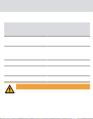
Mögliche unmittelbare Aus-
Signalwort (ANSI Z535.6)
Gefahr
Warnung
Vorsicht Leichte Verletzung
Achtung
Hinweis Geringe oder keine
WARNUNG
Versperrter Zugang
Durch fehlerhaft montierte und/oder programmierte Komponenten kann der Zutritt durch eine Tür
versperrt bleiben. Für Folgen eines versperrten Zutritts wie Zugang zu verletzten oder gefährdeten
Personen, Sachschäden oder anderen Schäden
wirkungen bei Nichtbeachtung
Tod oder schwere Verletzung (wahrscheinlich)
Tod oder schwere Verletzung (möglich, aber unwahrscheinlich)
Sachschäden oder Fehlfunktionen
Page 4
1. Allgemeine Sicherheitshinweise 4 / 124 | DE
haftet die SimonsVoss Technologies GmbH nicht!
WARNUNG
Versperrter Zugang durch Manipulation des Produkts
Wenn Sie das Produkt eigenmächtig verändern,
dann können Fehlfunktionen auftreten und der Zugang durch eine Tür versperrt werden.
Verändern Sie das Produkt nur bei Bedarf und
nur in der Dokumentation beschriebenen Art
und Weise.
ACHTUNG
Beschädigung durch elektrostatische Entladung (ESD)
Dieses Produkt enthält elektronische Bauteile, die durch
elektrostatische Entladungen beschädigt werden können.
1. Verwenden Sie ESD-gerechte Arbeitsmaterialien (z.B.
Erdungsarmband).
2. Erden Sie sich vor Arbeiten, bei denen Sie mit der Elektronik in Kontakt kommen könnten. Fassen Sie dazu geerdete metallische Oberflächen an (z.B, Türzargen,
Wasserrohre oder Heizungsventile).
Page 5

1. Allgemeine Sicherheitshinweise 5 / 124 | DE
ACHTUNG
Beschädigung durch Öle, Fette, Farben und Säuren
Dieses Produkt enthält elektronische Bauteile, die durch
Flüssigkeiten aller Art beschädigt werden können.
Halten Sie Öle, Fette, Farben und Säuren vom Produkt
fern.
ACHTUNG
Beschädigung durch mechanische Einwirkung
Dieses Produkt enthält elektronische Bauteile, die durch
mechanische Einwirkung aller Art beschädigt werden können.
1. Vermeiden Sie das Anfassen der Elektronik.
2. Vermeiden Sie sonstige mechanische Einwirkungen auf
die Elektronik.
ACHTUNG
Beschädigung durch Verpolung
Dieses Produkt enthält elektronische Bauteile, die durch die
Verpolung der Spannungsquelle beschädigt werden können.
Verpolen Sie die Spannungsquelle nicht (Batterien bzw.
Page 6

1. Allgemeine Sicherheitshinweise 6 / 124 | DE
Netzteile).
ACHTUNG
Störung des Betriebs durch Funkstörung
Dieses Produkt kann unter Umständen durch elektromagnetische oder magnetische Störungen beeinflusst werden.
Montieren bzw. platzieren Sie das Produkt nicht unmit-
telbar neben Geräten, die elektromagnetische oder magnetische Störungen verursachen können (Schaltnetzteile!).
ACHTUNG
Störung der Kommunikation durch metallische Oberflächen
Dieses Produkt kommuniziert drahtlos. Metallische Oberflächen können die Reichweite des Produkts erheblich reduzieren.
Montieren bzw. platzieren Sie das Produkt nicht auf oder
in der Nähe von metallischen Oberflächen.
Page 7
1. Allgemeine Sicherheitshinweise 7 / 124 | DE
HINWEIS
Bestimmungsgemäßer Gebrauch
SimonsVoss-Produkte sind ausschließlich für das
Öffnen und Schließen von Türen und vergleichbaren
Gegenständen bestimmt.
Verwenden Sie SimonsVoss-Produkte nicht für
andere Zwecke.
HINWEIS
Qualifikationen erforderlich
Die Installation und Inbetriebnahme setzt Fachkenntnisse voraus.
Nur geschultes Fachpersonal darf das Produkt
installieren und in Betrieb nehmen.
HINWEIS
Die deutsche Sprachfassung ist die Originalbetriebsanleitung. Andere Sprachen (Abfassung in der
Vertragssprache) sind Übersetzungen der Originalbetriebsanleitung.
Page 8
2. Allgemein 8 / 124 | DE
HINWEIS
Lesen Sie alle Anweisungen zur Installation, zum
Einbau und zur Inbetriebnahme und befolgen Sie
diese. Geben Sie diese Anweisungen und jegliche
Anweisungen zur Wartung an den Benutzer weiter.
2. Allgemein
Sie können jeden SmartCard .MP Zylinder nachträglich vernetzen.
Ab LSM 3.2
Konventionell: Produktion programmiert Adresse.
Autokonfiguration (WNM): WaveNet-Manager
programmiert Adresse.
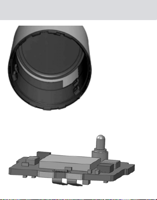
Lieferumfang:
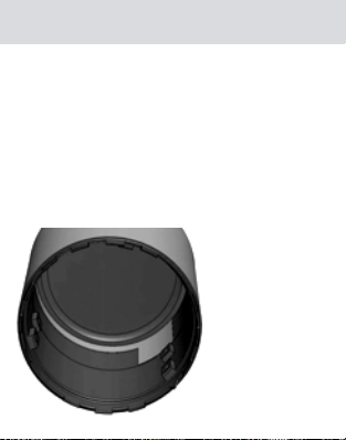
LockNode
Aufkleber mit Chip-ID
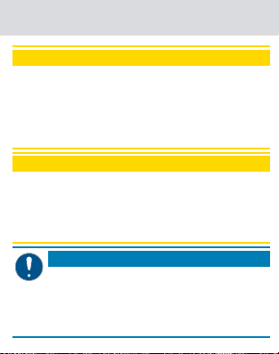
Knaufkappe mit Antennenfolie
Kurzanleitung
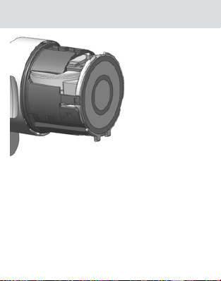
Der LockNode wird durch den Zylinder mit Strom versorgt.
Dazu ist eine Knaufkappe mit Kontaktierungsfolie erforderlich (im Lieferumfang):
Page 9
2. Allgemein 9 / 124 | DE
Sie können die bisherige Knaufkappe nicht mehr verwenden.
Der LockNode kontaktiert einerseits die Batterie, andererseits die Kontaktierungsfolie:
Page 10
3. Einbau 10 / 124 | DE
3. Einbau
1. Setzen Sie den Batterie-/Montageschlüssel am Knauf
der Elektronikseite so an, dass die beiden Nasen in die
Öffnungen der Rastscheibe eingreifen (Drehen Sie den
Knauf ggfs., bis die Nasen eingreifen).
HINWEIS
Der Batterie-/Montageschlüssel muss plan auf der
Innenseite des Knaufs aufliegen.
2. Halten Sie den Knauf fest und drehen Sie den Batterie-/
Page 11
3. Einbau 11 / 124 | DE
Montageschlüssel um etwa 30° im Uhrzeigersinn.
9 Rastscheibe/Knauf knackt.
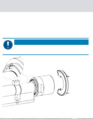
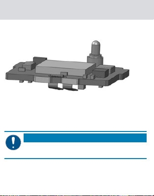
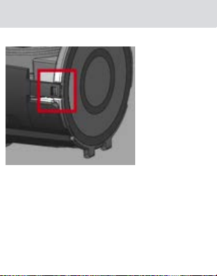
3. Schieben Sie die Griffmulde nach innen.
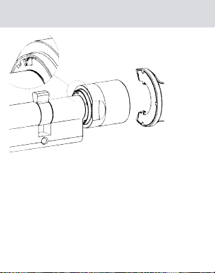
4. Drehen Sie die Knaufkappe bis zum Anschlag gegen den
Uhrzeigersinn.
5. Ziehen Sie die Knaufkappe ab.
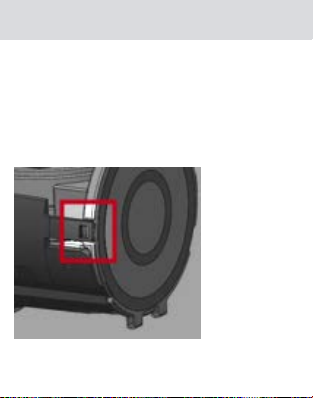
6. Biegen Sie vorsichtig die schwarzen Kunststoffhalterungen nach außen.
9 Kartenleserdeckel springt auf.
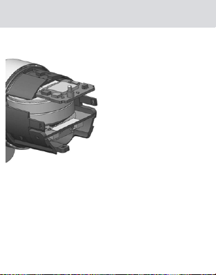
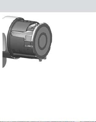
7. Schieben Sie den LockNode bis etwa zur Hälfte in die
Page 12
3. Einbau 12 / 124 | DE
dafür vorgesehenen Schlitze.
8. Schließen Sie den Kartenleserdeckel und drücken Sie ihn
fest, bis er in die schwarzen Kunststoffhalterungen einrastet.
9 LockNode ist fixiert.
Page 13
3. Einbau 13 / 124 | DE
9. Stecken Sie die mitgelieferte Knaufkappe mit der eingeklebten Kontaktfolie auf (Achten Sie auf die Markierungen).
9 Zylinder piepst viermal.
Page 14

3. Einbau 14 / 124 | DE
10. Drehen Sie die Knaufkappe bis zum Anschlag im Uhrzeigersinn.
11. Ziehen Sie die Griffmulde nach außen, bis sie bündig an
die Knaufkappe stößt.
12. Setzen Sie den Batterie-/Montageschlüssel am Knauf
der Elektronikseite so an, dass die beiden Nasen in die
Öffnungen der Rastscheibe eingreifen (Drehen Sie den
Knauf ggfs., bis die Nasen eingreifen).
13. Halten Sie den Knauf fest und drehen Sie den Batterie-/
Montageschlüssel um etwa 30° gegen den Uhrzeiger-
Page 15

4. Technische Daten 15 / 124 | DE
sinn.
9 Rastscheibe/Knauf knackt.
9 LockNode ist montiert.
Wenn der Zylinder nicht piept, dann kontrollieren Sie den
Batteriezustand.
Hinweis für SmartIntego-Nutzer
SimonsVoss empfiehlt die folgende Vorgehensweise:
1. Entfernen Sie den vorhandenen LockNode.
2. Montieren Sie wie beschrieben den neuen LockNode.
3. Öffnen Sie den SmartIntego-Manager.
4. Wählen Sie Ersetzen mit Chip-ID.
5. Geben Sie die neue Chip-ID ein.
6. Führen Sie die Programmierung im SmartIntego-Tool
durch.
7. Importieren Sie ggfs. in das Integratorsystem.
8. Aktualisieren Sie die Dokumentation (Einbauplan).
9 LockNode ist ersetzt. Verwenden Sie den alten
LockNode nicht mehr.
4. Technische Daten
Maße 16×18×7mm
Page 16

5. Konformitätserklärung 16 / 124 | DE
Gewicht 0,9g
-20°C bei 100%
Batteriekapazität bis
Temperaturbereich
Stromversorgung
+65°C (Betrieb)
-40°C bis +70°C
(Lagerung kurzfristig)
0°C bis +30°C
(Lagerung langfristig)
Über Zylinder (3VDC)
Standby: Bis zu 5Jahre
Betätigungen: Bis zu
80000
Funkemissionen
SRD (WaveNet)
Es liegen keine geografischen Beschränkungen innerhalb der
EU vor.
5. Konformitätserklärung
Hiermit erklärt die SimonsVoss Technologies GmbH , dass
868 MHz - 870
MHz
10dB (6,3mW)
Page 17

6. Hilfe und weitere Informationen 17 / 124 | DE
der Artikel WN(M).LN.I.MP(.WP)/SI.LN.I.MP(.WP) folgenden
Richtlinien entspricht:
2014/53/EU "Funkanlagen"
2014/30/EU "EMV"
2011/65/EU "RoHS"
2012/19/EU "WEEE"
sowie der Verordnung (EG) 1907/2006 "REACH"
Der vollständige Text der EU-Konformitätserklärung ist unter der folgenden Internetadresse verfügbar:
www.simons-voss.com/de/zertifikate.html
6. Hilfe und weitere Informationen
Infomaterial/Dokumente
Detaillierte Informationen zum Betrieb und zur Konfiguration
sowie weitere Dokumente finden Sie auf der SimonsVossHomepage im Downloadbereich unter Dokumente (
www.simons-voss.com/de/downloads/dokumente.html
Anleitungen
Detaillierte Informationen zum Betrieb und zur Konfiguration
https://
.
https://
).
Page 18
6. Hilfe und weitere Informationen 18 / 124 | DE
finden Sie im Internet auf unserer Homepage unter
www.smartintego.com
Konformitätserklärungen und Zertifikate
Konformitätserklärungen und Zertifikate zu diesem Produkt
finden Sie auf der SimonsVoss-Homepage im Zertifikatsbereich (
https://www.simons-voss.com/de/zertifikate.html
Informationen zur Entsorgung
Entsorgen Sie das Gerät (WN(M).LN.I.MP(.WP)/
SI.LN.I.MP(.WP)) nicht mit dem Hausmüll, sondern
gemäß der europäischen Richtlinie 2012/19/EU bei einer
kommunalen Sammelstelle für Elektro-Sonderabfälle.
Recyceln Sie defekte oder verbrauchte Batterien gemäß
der europäischen Richtlinie 2006/66/EG.
Beachten Sie örtliche Bestimmungen zur getrennten
Entsorgung von Batterien.
Führen Sie die Verpackung einer umweltgerechten
Wiederverwertung zu.
.
).
Page 19

6. Hilfe und weitere Informationen 19 / 124 | DE
Hotline
Bei technischen Fragen hilft Ihnen die SimonsVoss ServiceHotline unter +49 (0) 89 99 228 333 (Anruf in das deutsche
Festnetz, Kosten variieren je nach Anbieter).
E-Mail
Sie möchten uns lieber eine E-Mail schreiben?
support@simons-voss.com (System 3060, MobileKey)
si-support@simons-voss.com (SmartIntego)
SimonsVoss Technologies GmbH
Feringastraße 4
85774 Unterföhring
Deutschland
Page 20
1. General safety instructions 20 / 124 | EN
1. General safety instructions
Signal word (ANSI Z535.6)
DANGER
WARNING
CAUTION Minor injury
IMPORTANT
NOTE Low or none
WARNING
Blocked access
Access through a door may stay blocked due to incorrectly fitted and/or incorrectly programmed
components. SimonsVoss Technologies GmbH
not liable for the consequences of blocked access
such as access to injured or endangered persons,
material damage or other damage!
Possible immediate effects
of non-compliance
Death or serious injury
(likely)
Death or serious injury (possible, but unlikely)
Property damage or malfunction
is
Page 21
1. General safety instructions 21 / 124 | EN
WARNING
Blocked access through manipulation of the
product
If you change the product on your own, malfunctions can occur and access through a door can be
blocked.
Modify the product only when needed and only
in the manner described in the documentation.
IMPORTANT
Damage resulting from electrostatic discharge (ESD)
This product contains electronic components that may be
damaged by electrostatic discharges.
1. Use ESD-compliant working materials (e.g. Grounding
strap).
2. Ground yourself before carrying out any work that could
bring you into contact with the electronics. For this purpose, touch earthed metallic surfaces (e.g. door frames,
water pipes or heating valves).
Page 22

1. General safety instructions 22 / 124 | EN
IMPORTANT
Damage resulting from liquids
This product contains electronic components that may be
damaged by liquids of any kind.
Keep liquids away from the electronics.
IMPORTANT
Damage as a result of mechanical impact
This product contains electronic components that may be
damaged by mechanical impacts of any kind.
1. Avoid touching the electronics.
2. Avoid other mechanical influences on the electronics.
IMPORTANT
Damage due to polarity reversal
This product contains electronic components that may be
damaged by reverse polarity of the power source.
Do not reverse the polarity of the voltage source (batter-
ies or mains adapters).
Page 23
1. General safety instructions 23 / 124 | EN
IMPORTANT
Operational malfunction due to radio interference
This product may be affected by electromagnetic or magnetic interference.
Do not mount or place the product directly next to
devices that could cause electromagnetic or magnetic
interference (switching power supplies!).
IMPORTANT
Communication interference due to metallic surfaces
This product communicates wirelessly. Metallic surfaces
can greatly reduce the range of the product.
Do not mount or place the product on or near metallic
surfaces.
NOTE
Intended use
SimonsVoss-products are designed exclusively for
opening and closing doors and similar objects.
Do not use SimonsVoss products for any other
purposes.
Page 24

2. General 24 / 124 | EN
NOTE
Qualifications required
The installation and commissioning requires specialized knowledge.
Only trained personnel may install and commis-
sion the product.
NOTE
The German language version is the original instruction manual. Other languages (drafting in the contract language) are translations of the original instructions.
NOTE
Read and follow all installation, installation, and
commissioning instructions. Pass these instructions
and any maintenance instructions to the user.
2. General
You can network any SmartCard MP cylinder retroactively.
LSM 3.2 and higher
Conventional: Production programmed address.
Page 25
2. General 25 / 124 | EN
Autoconfiguration (WNM): WaveNet Manager
programmed address.
Included in delivery:
LockNode
Sticker with Chip-ID
Thumb-turn cover with antenna foil
Quick guide
The LockNode is powered by the cylinder. This requires a
thumb-turn cover with contact foil (included in delivery):
Page 26
3. Installation 26 / 124 | EN
You can no longer use the previous thumb-turn cover. The
LockNode contacts both the battery and the contact foil:
3. Installation
1. Place the battery/installation key on the electronic side
thumb-turn so that the two noses engage in the openings of the locking disc (if necessary, turn the thumb-turn
until the noses engage).
NOTE
The battery/installation key must lie flat on the inside of the thumb-turn.
Page 27
3. Installation 27 / 124 | EN
2. Hold the thumb-turn firmly and turn the battery/installation key clockwise about 30°.
9 The locking disc/thumb-turn cracks.
3. Push the recessed grip inwards.
4. Turn the thumb-turn cover counterclockwise until it
stops.
5. Remove the thumb-turn cover.
Page 28
3. Installation 28 / 124 | EN
6. Carefully bend the black plastic holders outwards.
9 Card reader cover pops open.
7. Push the LockNode about halfway into the designated
Page 29

3. Installation 29 / 124 | EN
slots.
8. Close the card reader cover and press it firmly until it
snaps into the black plastic holders.
9 LockNode is fixed.
Page 30
3. Installation 30 / 124 | EN
9. Attach the supplied thumb-turn cover with the glued-in
contact foil (pay attention to the markings).
9 Cylinder beeps four times.
Page 31

3. Installation 31 / 124 | EN
10. Turn the thumb-turn cover clockwise until it stops.
11. Pull the recessed grip outwards until it is flush with the
thumb-turn cover.
12. Place the battery/installation key on the electronic side
thumb-turn so that the two noses engage in the openings of the locking disc (if necessary, turn the thumb-turn
until the noses engage).
13. Hold the thumb-turn firmly and turn the battery/installation key about 30° counterclockwise.
9 The locking disc/thumb-turn cracks.
9 LockNode is mounted.
Page 32

4. Technical specifications 32 / 124 | EN
If the cylinder does not beep, check the battery condition.
Information for SmartIntego users
SimonsVoss recommends the following procedure:
1. Remove the existing LockNode.
2. Mount the new LockNode as described.
3. Open the SmartIntego Manager.
4. Select Replace with Chip ID.
5. Enter the new chip ID.
6. Carry out programming in the SmartIntego tool.
7. If necessary, import into the integrator system.
8. Update the documentation (installation plan).
9 LockNode is replaced. Do not use the old LockNode
anymore.
4. Technical specifications
Dimensions 16×18×7mm
Weight 0.9g
Page 33

5. Declaration of conformity 33 / 124 | EN
-20 °C at 100% battery
capacity up to +65°C
Temperature range
Power supply
(operation)
-40 °C to +70 °C (short-
term storage)
0 °C to +30 °C (long-
term storage)
Via cylinder (3VDC)
Standby: Up to 3 years
Activation Up to 32500
Radio emissions
SRD (WaveNet)
There are no geographical restrictions within the EU.
5. Declaration of conformity
The company SimonsVoss Technologies GmbH hereby declares that article WN(M).LN.I.MP(.WP)/SI.LN.I.MP(.WP)
complies with the following guidelines:
2014/53/EU "Radio equipment"
868 MHz - 870
MHz
10dB (6,3mW)
Page 34

6. Help and other information 34 / 124 | EN
2014/30/EU "EMC"
2011/65/EU "RoHS"
2012/19/EU "WEEE"
and regulation (EG) 1907/2006 "REACH"
The full text of the EU Declaration of conformity is available
at the following internet address:
voss.com/en/certificates.html
6. Help and other information
Information material/documents
You will find detailed information on operation and configuration and other documents under Informative material/
Documents in the Download section on the SimonsVoss
website (
https://www.simons-voss.com/en/downloads/
documents.html
Instruction manuals
You will find detailed information on operation and configuration online on our homepage at www.smartintego.com
Declarations of conformity
You will find declarations of conformity for this product in
).
https://www.simons-
.
.
Page 35

6. Help and other information 35 / 124 | EN
the Certificate section on the SimonsVoss website (
www.simons-voss.com/en/certificates.html
Information on disposal
Do not dispose the device (WN(M).LN.I.MP(.WP)/
SI.LN.I.MP(.WP)) in the household waste. Dispose of it at
a collection point for electronic waste as per European
Directive 2012/19/EU.
Recycle defective or used batteries in line with European
Directive 2006/66/EC.
Observe local regulations on separate disposal of
batteries.
Take the packaging to an environmentally responsible
recycling point.
Hotline
If you have any questions, the SimonsVoss Service Hotline
will be happy to help you on +49 (0)89 99 228 333 (German fixed network; call charges vary depending on the op-
https://
).
Page 36

6. Help and other information 36 / 124 | EN
erator).
Email
You may prefer to send us an email.
support@simons-voss.com (System 3060, MobileKey)
si-support@simons-voss.com (SmartIntego)
SimonsVoss Technologies GmbH
Feringastrasse 4
85774 Unterföhring
Germany
Page 37

1. Consignes de sécurité générales 37 / 124 | FR
1. Consignes de sécurité générales
Mot indicateur (ANSI
Z535.6)
DANGER
AVERTISSEMENT
ATTENTION Blessure légère
ATTENTION
REMARQUE Peu ou pas
AVERTISSEMENT
Accès bloqué
Toute erreur de montage et/ou de programmation
d'un composant peut bloquer l'accès par une porte.
La société SimonsVoss Technologies GmbH
toute responsabilité quant aux conséquences d'un
accès bloqué, par exemple, accès pour les per-
sonnes blessées ou en danger, dommages maté-
Effets immédiats possibles
du non-respect
Mort ou blessure grave (probable)
Mort ou blessure grave (possible, mais improbable)
Dommages matériels ou
dysfonctionnements
décline
Page 38

1. Consignes de sécurité générales 38 / 124 | FR
riels ou autres dommages!
AVERTISSEMENT
Accès bloqué par la manipulation du produit
Si vous modifiez vous-même le produit, des dysfonctionnements peuvent se produire et l'accès
peut être bloqué par une porte.
Ne changer le produit que lorsque cela est né-
cessaire et de la manière décrite dans la documentation.
ATTENTION
Endommagement lié à une décharge électrostatique
(DES)
Ce produit contient des composants électroniques susceptibles d’être endommagés par des décharges électrostatiques.
1. Utilisez du matériel de travail adapté à la DES (par ex. un
bracelet de mise à la terre).
2. Reliez-vous à la terre avant de commencer les travaux
pendant lesquels vous pouvez être en contact avec le
système électronique. Saisissez pour cela des surfaces
métalliques mises à la terre (par ex. huisseries de porte,
Page 39

1. Consignes de sécurité générales 39 / 124 | FR
conduites d’eau ou vannes de chauffage).
ATTENTION
Endommagement lié à des liquides
Ce produit contient des composants électroniques susceptibles d’être endommagés par tout type de liquide.
Tenez les liquides à l’écart du système électronique.
ATTENTION
Endommagement lié à une action mécanique
Ce produit contient des composants électroniques susceptibles d’être endommagés par une action mécanique quelconque.
1. Évitez de toucher le système électronique.
2. Évitez toute autre action mécanique sur le système électronique.
ATTENTION
Endommagement lié à une inversion de polarité
Ce produit contient des composants électroniques susceptibles d’être endommagés par une inversion de polarité de la
Page 40

1. Consignes de sécurité générales 40 / 124 | FR
source de tension.
N'inversez pas la polarité de la source de tension (piles
ou blocs d'alimentation).
ATTENTION
Défaillance du fonctionnement liée à une perturbation radioélectrique
Dans certaines circonstances, ce produit peut être entravé
par des perturbations électromagnétiques.
Ne placez pas le produit à proximité immédiate d’appa-
reils pouvant générer des perturbations électromagnétiques (alimentations à découpage!).
ATTENTION
Défaillance de la communication liée à des surfaces métalliques
Ce produit communique sans fil. Les surfaces métalliques
peuvent réduire considérablement le rayon d’action du produit.
Ne placez pas le produit sur des surfaces métalliques.
Page 41

1. Consignes de sécurité générales 41 / 124 | FR
REMARQUE
Utilisation conforme aux dispositions
Les produits SimonsVoss sont exclusivement destinés à l’ouverture et la fermeture de portes et d’objets similaires.
N’utilisez pas les produits SimonsVoss à
d’autres fins.
REMARQUE
Qualifications requises
L'installation et la mise en service nécessitent des
connaissances spécialisées.
Seul le personnel qualifié peut installer et
mettre en service le produit.
REMARQUE
La version allemande est le manuel d’instruction
original. Les autres langues (rédaction dans la
langue du contrat) sont des traductions des instructions originales.
Page 42

2. Généralités 42 / 124 | FR
REMARQUE
Lisez et suivez toutes les instructions d'installation,
d'installation et de mise en service. Transmettez
ces instructions et toutes les instructions de maintenance à l'utilisateur.
2. Généralités
Vous pouvez mettre en réseau les cylindres SmartCard .MP
à tout moment.
À partir de LSM 3.2
De manière conventionnelle: adresse programmée lors
de la production.
Configuration automatique (WNM): adresse
programmée par le gestionnaire WaveNet.
Fourniture:
LockNode
Autocollant avec ID de puce
Cache de poignée avec film d'antenne
Guide abrégé
Le LockNode est alimenté en courant par le cylindre. Pour
cela, un cache de poignée avec film de contact est néces-
Page 43

2. Généralités 43 / 124 | FR
saire (dans la fourniture):
Vous ne pouvez plus utiliser le cache de poignée actuel. Le
LockNode est en contact d'un côté avec la pile et de l'autre
avec le film de contact:
Page 44

3. Montage 44 / 124 | FR
3. Montage
1. Placez la clé de montage / de remplacement des piles
sur le bouton du côté électronique de sorte que les deux
ergots s'enclenchent dans les ouvertures du disque d'arrêt (si nécessaire, tournez le bouton jusqu'à ce que les
ergots s'enclenchent).
REMARQUE
La clé de montage / de remplacement des piles
doit reposer à plat sur le côté intérieur du bouton.
2. Tenez fermement le bouton et tournez la clé de mon-
Page 45

3. Montage 45 / 124 | FR
tage / de remplacement des piles de 30° environ dans
le sens horaire.
9 Le disque d'arrêt/le bouton s'ouvre.
3. Poussez la bague encastrée vers l'intérieur.
4. Tournez le cache du bouton dans le sens antihoraire jusqu'en butée.
5. Retirez le cache de la poignée.
6. Pliez avec précaution les supports noirs en plastique vers
l'extérieur.
9 Le couvercle du lecteur de cartes s'ouvre.
7. Poussez le noeud de réseau à peu près à moitié dans les
Page 46

3. Montage 46 / 124 | FR
fentes prévues à cet effet.
8. Fermez le couvercle du lecteur de cartes et poussez-le
fermement jusqu'à ce qu'il s'enclenche dans les supports noirs en plastique.
9 Le LockNode est fixé.
Page 47

3. Montage 47 / 124 | FR
9. Mettez le cache de poignée fourni en place avec le film
de contact collé (respectez les repères).
9 Le cylindre émet quatre bips.
Page 48

3. Montage 48 / 124 | FR
10. Tournez le cache du bouton dans le sens horaire jusqu'en butée.
11. Tirez la bague encastrée vers l'extérieur jusqu'à ce
qu'elle entre en contact avec le cache du cylindre.
12. Placez la clé de montage / de remplacement des piles
sur le bouton du côté électronique de sorte que les deux
ergots s'enclenchent dans les ouvertures du disque d'arrêt (si nécessaire, tournez le bouton jusqu'à ce que les
ergots s'enclenchent).
13. Tenez fermement le bouton et tournez la clé de montage / de remplacement des piles de 30° environ dans
Page 49

4. Caractéristiques techniques 49 / 124 | FR
le sens antihoraire.
9 Le disque d'arrêt/le bouton s'ouvre.
9 Le noeud de réseau est monté.
Si le cylindre n'émet pas de bip, contrôlez l'état de la pile.
Note pour les utilisateurs de SmartIntego
SimonsVoss recommande la procédure suivante :
1. Supprimer le LockNode existant.
2. Installez le nouveau LockNode comme décrit.
3. Ouvrez le SmartIntego Manager.
4. Sélectionnez Replace with Chip ID.
5. Entrez le nouvel ID de puce.
6. Effectuer la programmation dans l'outil SmartIntego.
7. Si nécessaire, l'importer dans le système intégrateur.
8. Mettre à jour la documentation (plan d'installation).
9 LockNode est remplacé. N'utilisez plus l'ancien
LockNode.
4. Caractéristiques techniques
Dimensions 16×18×7mm
Poids 0,9g
Page 50

5. Déclaration de conformité 50 / 124 | FR
De -20°C pour une
capacité de la pile de
100% à +65°C
Plage de températures
Alimentation électrique
(fonctionnement)
De -40°C à +70°C
(stockage temporaire)
De 0°C à +30°C
(stockage à long terme)
Par le cylindre (3VCC)
Veille: Jusqu’à 3ans
Actionnements: Jusqu’à
32500
Émissions de radio
SRD (WaveNet)
Il n'y a pas de restrictions géographiques au sein de l'UE.
5. Déclaration de conformité
La société SimonsVoss Technologies GmbH déclare par la
présente que l'article WN(M).LN.I.MP(.WP)/
868 MHz - 870
MHz
10dB (6,3mW)
Page 51

6. Aide et autres informations 51 / 124 | FR
SI.LN.I.MP(.WP) est conforme aux directives suivantes
2014/53/EU "Dispositif de radio"
2014/30/EU "EMV"
2011/65/EU "RoHS"
2012/19/EU "WEEE"
et le règlement (EG) 1907/2006 "REACH"
Le texte intégral de la déclaration de conformité CE est disponible à l'adresse Internet suivante :
voss.com/fr/certificats.html
6. Aide et autres informations
Documentation/documents
Les informations détaillées concernant le fonctionnement
et la configuration peuvent être consultées sur la page d’accueil de SimonsVoss dans la section téléchargements sous
documentation (
chargements/documents.html
Instructions
Vous trouverez des informations détaillées concernant le
https://www.simons-voss.com/fr/tele-
https://www.simons-
.
).
Page 52

6. Aide et autres informations 52 / 124 | FR
fonctionnement et la configuration sur notre page d'accueil
sous www.smartintego.com
Déclarations de conformité
Les déclarations de conformité relatives à ce produit
peuvent être consultées sur la page d’accueil SimonsVoss,
dans la section certificats (
fr/certificats.html
Informations sur l'elimination
Ne jetez pas l’appareil (WN(M).LN.I.MP(.WP)/
SI.LN.I.MP(.WP)) avec vos ordures ménagères mais
dans un point de collecte communal pour appareils
électriques et appareils spéciaux conformément à la
directive européenne 2012/19/UE.
Recyclez les piles défectueuses ou usées conformément
à la directive européenne 2006/66/CE.
Veuillez tenir compte des dispositions locales
applicables concernant la collecte séparée des piles.
Recyclez l’emballage d’une manière écologique.
.
https://www.simons-voss.com/
).
Page 53

6. Aide et autres informations 53 / 124 | FR
Hotline
En cas de questions techniques, contactez la Hotline SimonsVoss au +49 (0) 89 99 228 333 (appel vers le réseau
fixe allemand, coût variable en fonction de l'opérateur).
E-Mail
Vous préférez nous envoyer un e-mail?
support@simons-voss.com (Système 3060, MobileKey)
si-support@simons-voss.com (SmartIntego)
SimonsVoss Technologies GmbH
Feringastrasse 4
85774 Unterföhring
Allemagne
Page 54

1. Algemene veiligheidsinstructies 54 / 124 | NL
1. Algemene veiligheidsinstructies
Signaalwoord (ANSI
Z535.6)
GEVAAR
WAARSCHUWING
VOORZICHTIG Lichte verwonding
LET OP Materiële schade of storing
OPMERKING Laag of nee
WAARSCHUWING
Geblokkeerde toegang
Door foutief geïnstalleerde en/of geprogrammeerde
componenten kan de doorgang door een deur geblokkeerd blijven. Voor gevolgen van een geblokkeerde toegang tot gewonden of personen in gevaar, materiële of andere schade, is SimonsVoss
Technologies GmbH niet aansprakelijk.
Mogelijke onmiddellijke gevolgen van niet-naleving
Dood of ernstig letsel (waarschijnlijk)
Dood of ernstig letsel (mogelijk, maar onwaarschijnlijk)
Page 55

1. Algemene veiligheidsinstructies 55 / 124 | NL
WAARSCHUWING
Geblokkeerde toegang als gevolg van manipulatie
van het product
Als u het product zelf wijzigt, kunnen er storingen
optreden en kan de toegang worden geblokkeerd
door een deur.
Vervang het product alleen wanneer dat nodig is
en op de manier die in de documentatie wordt
beschreven.
LET OP
Beschadiging door elektrostatische ontlading (ESD)
Dit product heeft elektronische componenten die kunnen
worden beschadigd door een elektrostatische ontlading.
1. Maak gebruik van ESD-conforme materialen (bijv. aardingsarmband).
2. Zorg dat u geaard bent voor werkzaamheden waarbij u
met de elektronica in contact kunt komen. Gebruik hiervoor geaarde metalen oppervlakken (bijv. Deurposten,
waterleidingen of verwarmingsbuizen).
Page 56

1. Algemene veiligheidsinstructies 56 / 124 | NL
LET OP
Beschadiging door vloeistoffen
Dit product heeft elektronische componenten die kunnen
worden beschadigd door elk type vloeistof.
Houd vloeistoffen uit de buurt van de elektronica.
LET OP
Beschadiging door mechanische impact
Dit product heeft elektronische componenten die kunnen
worden beschadigd door elk type mechanische impact.
1. Vermijd dat u de elektronica aanraakt.
2. Vermijd ook andere mechanische impact op de elektronica.
LET OP
Beschadiging door verwisseling van de polariteit
Dit product bevat elektronische componenten die door verwisseling van de polariteit van de voedingsbron beschadigd
kunnen worden.
Verwissel de polariteit van de voedingsbron niet (batte-
rijen of netadapters).
Page 57

1. Algemene veiligheidsinstructies 57 / 124 | NL
LET OP
Storing van het gebruik door verbroken verbinding
Dit product kan onder bepaalde omstandigheden beïnvloed
worden door elektromagnetische of magnetische storingen.
Monteer of plaats het product niet direct in de buurt van
apparaten die elektromagnetische of magnetische storingen kunnen veroorzaken (stroomschakelaars!).
LET OP
Storing van de communicatie door metalen oppervlakken
Dit product communiceert draadloos. Metalen oppervlakken
kunnen het zendbereik van het product aanzienlijk verminderen.
Monteer of plaats het product niet op of in de buurt van
metalen oppervlakken.
OPMERKING
Beoogd gebruik
SimonsVoss-producten zijn uitsluitend bedoeld
voor het openen en sluiten van deuren en vergelijk-
Page 58

2. Algemeen 58 / 124 | NL
bare voorwerpen.
Gebruik SimonsVoss-producten niet voor ande-
re doeleinden.
OPMERKING
Kwalificaties vereist
De installatie en inbedrijfstelling vereist gespecialiseerde kennis. Alleen getraind personeel mag het
product installeren en in bedrijf stellen.
OPMERKING
De Duitse taalversie is de originele handleiding. Andere talen (opstellen in de contracttaal) zijn vertalingen van de originele instructies.
OPMERKING
Lees en volg alle installatie-, installatie- en inbedrijfstellingsinstructies. Geef deze instructies en eventuele onderhoudsinstructies door aan de gebruiker.
2. Algemeen
U kunt iedere SmartCard .MP cilinder achteraf opnemen in
een netwerk.
Page 59

2. Algemeen 59 / 124 | NL
Vanaf LSM 3.2
Conventioneel: Productie programmeert het adres.
Autoconfiguratie (WNM): WaveNet Manager
programmeert het adres.
In de levering inbegrepen:
LockNode
Sticker met Chip ID
Knopkapje met antennefolie
Korte handleiding
De LockNode ontvangt voeding via de cilinder. Daarvoor is
een knopkapje met contactfolie nodig (meegeleverd):
Page 60

2. Algemeen 60 / 124 | NL
u kunt het bestaande knopkapje niet meer gebruiken. De
LockNode maakt enerzijds contact met de batterij en anderzijds met de contactfolie:
Page 61

3. Montage 61 / 124 | NL
3. Montage
1. Plaats de batterij-/montagesleutel op de knop van de
zijde met elektronica zodanig dat de twee neuzen in de
opening van de vast klikkende schijf grijpen (draai de
knop eventueel totdat de neuzen pakken).
OPMERKING
De batterij-/montagesleutel moet vlak tegen de
binnenzijde van de knop aan liggen.
2. Houd de knop goed vast en draai de batterij-/montage-
Page 62

3. Montage 62 / 124 | NL
sleutel circa 30° rechtsom.
9 De schijf/knop klikt.
3. Schuif de inkeping van de greep naar binnen.
4. Draai het knopkapje tot de aanslag linksom.
5. Neem nu het knopkapje weg.
6. Buig de zwarte kunststof houders behoedzaam naar buiten.
9 De deksel van de kaartlezer springt open.
7. Schuif de LockNode tot ongeveer de helft in de hiervoor
Page 63

3. Montage 63 / 124 | NL
bestemde sleuf.
8. Sluit de deksel van de kaartlezer en druk hem vast totdat
hij weer vastklikt in de zwarte kunststof houders.
9 De LockNode is vastgezet.
Page 64

3. Montage 64 / 124 | NL
9. Breng het meegeleverde knopkapje met de opgelijmde
contactfolie aan (let goed op de markeringen).
9 De cilinder piept vier keer.
Page 65

3. Montage 65 / 124 | NL
10. Draai het knopkapje tot de aanslag rechtsom.
11. Trek de inkeping van de greep naar buiten, tot deze uitgelijnd tegen het knopkapje aan stoot.
12. Plaats de batterij-/montagesleutel op de knop van de
zijde met elektronica zodanig dat de twee neuzen in de
opening van de vast klikkende schijf grijpen (draai de
knop eventueel totdat de neuzen pakken).
13. Houd de knop goed vast en draai de batterij-/montagesleutel circa 30° linksom.
9 De schijf/knop klikt.
9 De LockNode is gemonteerd.
Page 66

4. Technische gegevens 66 / 124 | NL
Wanneer de cilinder niet piept, moet u de batterijstatus controleren.
Aanwijzing voor gebruikers van SmartIntego
SimonsVoss adviseert de volgende handelwijze:
1. verwijder de aanwezige LockNode.
2. Monteer de nieuwe LockNode volgens de beschrijving.
3. Roep de SmartIntego Manager op.
4. Kies Replace with Chip ID.
5. Voer de nieuwe chip-id in.
6. Voer de programmering uit in de SmartIntego-tool.
7. Importeer evt. in het Integratorsysteem.
8. Actualiseer de documentatie (montageplan).
9 De LockNode is vervangen. Gebruik de oude LockNode
niet meer.
4. Technische gegevens
Afmetingen 16×18×7mm
Gewicht 0,9g
Page 67

5. Verklaring van overeenstemming 67 / 124 | NL
-20°C bij 100%
batterijcapaciteit tot
Temperatuurbereik
Stroomverzorging
+65°C (gebruik)
-40°C tot +70°C
(kortstondige opslag)
0°C tot +30°C,
(langdurige opslag)
Via cilinder (3VDC)
Stand-by: tot 3 jaar
Activeringen: max.
32.500
Radio-emissies
SRD (WaveNet)
Er zijn geen geografische beperkingen binnen de EU.
5. Verklaring van overeenstemming
Het bedrijf SimonsVoss Technologies GmbH verklaart hierbij
dat artikel WN(M).LN.I.MP(.WP)/SI.LN.I.MP(.WP)
aan de volgende richtlijnen
868 MHz - 870
MHz
10dB (6,3mW)
voldoet
Page 68

6. Hulp en verdere informatie 68 / 124 | NL
2014/53/EU "Radioapparatuur"
2014/30/EU "EMC"
2011/65/EU "RoHS"
2012/19/EU "WEEE"
en de verordening (EG) 1907/2006 "REACH"
De volledige tekst van de EU-conformiteitsverklaring is beschikbaar op het volgende internetadres:
mons-voss.com/nl/certificaten.html
6. Hulp en verdere informatie
Informatiemateriaal/documenten
Gedetailleerde informatie over het gebruik en de configuratie, alsook overige documentatie vindt u op de homepage
van SimonsVoss in het menupunt Downloads onder Documenten (
https://www.simons-voss.com/nl/downloads/documenten.html
Instructies
Gedetailleerde informatie over de bediening en de configuratie kunt u vinden op onze homepage onder www.smartintego.com.
).
https://www.si-
.
Page 69

6. Hulp en verdere informatie 69 / 124 | NL
Conformiteitsverklaringen
Conformiteitsverklaringen voor dit product vindt u op de homepage van SimonsVoss onder het menupunt Certificaten
(
https://www.simons-voss.com/nl/certificaten.html
Informatie over verwijdering
Voer het apparaat (WN(M).LN.I.MP(.WP)/
SI.LN.I.MP(.WP)) niet af als huishoudelijk afval, maar
overeenkomstig de Europese Richtlijn 2012/19/EU bij een
gemeentelijke inzamelpunt voor speciaal
elektrotechnisch afval.
Zorg voor recycling van defecte of gebruikte batterijen
volgens de Europese Richtlijn 2006/66/EG.
Neem de plaatselijke bepalingen in acht voor de
gescheiden afvoer van batterijen.
Voer de verpakking af naar een instantie voor
milieuvriendelijke recycling.
).
Page 70

6. Hulp en verdere informatie 70 / 124 | NL
Hotline
Bij technische vragen is de SimonsVoss Service Hotline u
graag van dienst onder +49 (0) 89 99 228 333 (telefoongesprek in het vaste Duitse telefoonnet, kosten afhankelijk van
de aanbieder).
E-mail
Schrijft u ons liever een e-mail?
support@simons-voss.com (Systeem 3060, MobileKey)
si-support@simons-voss.com (SmartIntego)
SimonsVoss Technologies GmbH
Feringastraße 4
85774 Unterföhring
Duitsland
Page 71

1. Avvisi di sicurezza generali 71 / 124 | IT
1. Avvisi di sicurezza generali
Avvertenza (ANSI Z535.6)
PERICOLO
AVVERTENZA
ATTENZIONE Lieve ferita
AVVISO
NOTA Basso o no
AVVERTENZA
Accesso bloccato
Con componenti montati e/o programmati in modo
difettoso, l'accesso attraverso una porta può resta-
re bloccato. La SimonsVoss Technologies GmbH
non risponde delle conseguenze di un accesso bloc-
cato, per esempio nel caso si debba accedere a
persone ferite o in pericolo, di danni a cose o altri
Possibili effetti immediati di
non conformità
Morte o lesioni gravi (probabile)
Morte o lesioni gravi (possibili, ma improbabili)
Danni materiali o malfunzionamento
Page 72

1. Avvisi di sicurezza generali 72 / 124 | IT
danni!
AVVERTENZA
Accesso bloccato tramite manipolazione del prodotto
Se si modifica il prodotto da solo, possono verificarsi malfunzionamenti e l'accesso attraverso una porta può essere bloccato.
Modificare il prodotto solo quando necessario e
solo nel modo descritto nella documentazione.
AVVISO
Danni dovuti a scariche elettrostatiche (ESD)
Il presente prodotto contiene componenti elettronici che
potrebbero subire danni in conseguenza di scariche elettrostatiche.
1. Utilizzare materiali di lavori conformi ai requisiti ESD (ad
es. fascetta antistatica al polso).
2. Effettuare la messa a terra dell’operatore prima di ese-
guire lavori in cui è possibile entrare in contatto con parti
elettroniche. A tale scopo, toccare una superficie metallica opportunamente messa a terra (ad es. telaio porta,
Page 73

1. Avvisi di sicurezza generali 73 / 124 | IT
tubi dell’acqua o valvole di riscaldamento).
AVVISO
Danni dovuti a fluidi
Il presente prodotto contiene componenti elettronici che
potrebbero subire danni dovuti a liquidi di qualunque tipo.
Tenere i componenti elettronici lontani da liquidi.
AVVISO
Danni dovuti a effetti meccanici
Il presente prodotto contiene componenti elettronici che
potrebbero subire danni dovuti a effetti meccanici di qualunque tipo.
1. Evitare di toccare le parti elettroniche.
2. Evitare ulteriori effetti meccanici sulle parti elettroniche.
AVVISO
Danni dovuti all'inversione di polarità
Questo prodotto contiene componenti elettronici che possono essere danneggiati dall'inversione di polarità della sorgente di tensione.
Non invertire la polarità della sorgente di tensione (bat-
Page 74

1. Avvisi di sicurezza generali 74 / 124 | IT
terie o alimentatori).
AVVISO
Funzionamento disturbato a causa di interferenze radioelettriche
Questo prodotto potrebbe essere influenzato da disturbi
elettromagnetici o magnetici.
Non montare o posizionare il prodotto direttamente ac-
canto a dispositivi che possono causare interferenze
elettromagnetiche o magnetiche (alimentatori switching!).
AVVISO
Interferenze nella comunicazione dovute a superfici metalliche
Questo prodotto comunica in modalità wireless. Le superfici
metalliche possono ridurre significativamente la portata del
prodotto.
Non montare o posizionare il prodotto sopra o vicino a
superfici metalliche.
Page 75

1. Avvisi di sicurezza generali 75 / 124 | IT
NOTA
Uso conforme
I prodotti SimonsVoss sono concepiti esclusiva-
mente per l’apertura e la chiusura di porte e oggetti
simili.
Non utilizzare i prodotti SimonsVoss per altri
scopi.
NOTA
Qualifiche richieste
L'installazione e la messa in servizio richiedono co-
noscenze specialistiche.
Solo personale qualificato può installare e met-
tere in servizio il prodotto.
NOTA
La versione in lingua tedesca è il manuale di istru-
zioni originale. Altre lingue (redazione nella lingua
del contratto) sono traduzioni delle istruzioni origi-
nali.
Page 76

2. Informazioni generali 76 / 124 | IT
NOTA
Leggere e seguire tutte le istruzioni di installazione,
installazione e messa in servizio. Passare queste
istruzioni e tutte le istruzioni di manutenzione
all'utente.
2. Informazioni generali
È possibile collegare in rete qualsiasi cilindro SmartCard .MP
in un secondo tempo.
A partire da LSM 3.2
Convenzionale: Indirizzo programmato nella produzione.
Autoconfigurazione (WNM): Indirizzo programmato da
WaveNet Manager.
Oggetto di fornitura:
LockNode
Adesivo con ID Chip
Cappellotto pomolo con pellicola antenna
Libretto
Il LockNode è alimentato dal cilindro. A tale scopo è necessario un cappellotto pomolo con pellicola di contatto (inclusa nella fornitura):
Page 77

2. Informazioni generali 77 / 124 | IT
Non è più possibile utilizzare il cappellotto del pomolo precedente. Il LockNode entra in contatto sia con la batteria
che con la pellicola di contatto:
Page 78

3. Installazione 78 / 124 | IT
3. Installazione
1. Posizionare la chiave di montaggio/per batteria sul po-
molo lato elettronica in modo che i due naselli si innestino nelle aperture del disco di arresto (se necessario ruotare il pomolo finché i naselli si agganciano).
NOTA
La chiave di montaggio/per batteria deve essere
posizionata piatta sulla superficie interna del pomolo.
2. Tenere fermo il pomolo e ruotare con cautela la chiave
Page 79

3. Installazione 79 / 124 | IT
di montaggio/per batteria di circa 30° in senso orario
9 fino a che l’assieme disco di arresto/pomolo emette
un clic.
3. Spingere l'impugnatura incassata verso l'interno.
4. Ruotare il cappellotto del pomolo in senso antiorario fino all'arresto.
5. Rimuovere il cappellotto del pomolo.
6. Piegare con attenzione i supporti in plastica nera verso
l'esterno.
9 Il coperchio del lettore di schede si apre.
7. Spingere il LockNode circa a metà strada nelle fessure
Page 80

3. Installazione 80 / 124 | IT
previste.
8. Chiudere il coperchio del lettore di schede e premerlo
con decisione fino a quando non scatta nei supporti di
plastica nera.
9 Il LockNode è fissato.
Page 81

3. Installazione 81 / 124 | IT
9. Fissare il cappellotto del pomolo in dotazione con la pellicola di contatto incollata in posizione (fare attenzione
alle marcature).
9 Il cilindro emette quattro bip.
Page 82

3. Installazione 82 / 124 | IT
10. Ruotare il cappellotto del pomolo in senso orario fino
all'arresto.
11. Tirare l'impugnatura incassata verso l'esterno finché non
è a filo con il cappellotto del pomolo.
12. Posizionare la chiave di montaggio/per batteria sul pomolo lato elettronica in modo che i due naselli si innestino nelle aperture del disco di arresto (se necessario ruotare il pomolo finché i naselli si agganciano).
13. Tenere saldamente il pomolo e ruotare la chiave di
montaggio/batteria di circa 30° in senso antiorario.
9 fino a che l’assieme disco di arresto/pomolo emette
Page 83

4. Dati tecnici 83 / 124 | IT
un clic.
9 Il LockNode è montato.
Se il cilindro non emette alcun segnale acustico, controllare
lo stato della batteria.
Nota per gli utenti di SmartIntego
SimonsVoss raccomanda la seguente procedura:
1. Rimuovere il LockNode esistente.
2. Montare il nuovo LockNode come descritto.
3. Aprire SmartIntego Manager.
4. Selezionare Replace with Chip ID.
5. Immettere il nuovo ID Chip.
6. Eseguire la programmazione nel tool SmartIntego.
7. Se necessario, importare nel sistema di integrazione.
8. Aggiornare la documentazione (piano di installazione).
9 Il LockNode è sostituito. Non utilizzare più il vecchio
LockNode.
4. Dati tecnici
Dimensioni 16×18×7mm
Peso 0,9g
Page 84

5. Dichiarazione di conformità 84 / 124 | IT
-20 °C al 100% della
capacità della batteria
fino a +65°C
Range di temperature
Alimentazione
(funzionamento)
da -40°C a +70°C
(stoccaggio breve)
da 0°C a +30°C
(stoccaggio prolungato)
Tramite cilindro (3VDC)
Standby: Fino a 3 anni
Azionamenti: Fino a
32.500
Emissioni radio
SRD (WaveNet)
Non esistono restrizioni geografiche all'interno dell'UE.
5. Dichiarazione di conformità
La società XY SimonsVoss Technologies GmbH dichiara che
l'articolo WN(M).LN.I.MP(.WP)/SI.LN.I.MP(.WP)
868 MHz - 870
MHz
10dB (6,3mW)
è conforme
Page 85

6. Supporto e ulteriori informazioni 85 / 124 | IT
alle seguenti linee guida
2014/53/EU "Apparecchiature radio"
2014/30/EU "CEM"
2011/65/EU "RoHS"
2012/19/EU "WEEE"
e il regolamento (EG) 1907/2006 "REACH"
Il testo integrale della dichiarazione di conformità UE è disponibile al seguente indirizzo Internet:
mons-voss.com/it/certificati.html
6. Supporto e ulteriori informazioni
Materiale informativo/Documenti
Maggiori informazioni sul funzionamento e sulla configurazione nonché ulteriori documenti sono riportati nella homepage di SimonsVoss, nell’area Download alla voce Documenti (
https://www.simons-voss.com/it/download/docu-
menti.html
).
Manuali
Per informazioni dettagliate sul funzionamento e sulla confi-
https://www.si-
.
Page 86

6. Supporto e ulteriori informazioni 86 / 124 | IT
gurazione, consultare la nostra homepage all'indirizzo
www.smartintego.com
Dichiarazioni di conformità
Le dichiarazioni di conformità relative a questo prodotto sono riportate nella homepage di SimonsVoss nell’area Certificati (
https://www.simons-voss.com/it/certificati.html
Informazioni sullo smaltimento
Il dispositivo (WN(M).LN.I.MP(.WP)/SI.LN.I.MP(.WP))
non va smaltito fra i rifiuti domestici, ma conferito presso
un centro di raccolta comunale per rifiuti elettronici
speciali in conformità con la Direttiva Europea 2012/19/
UE.
Riciclare le batterie guaste o esauste ai sensi della
Direttiva Europea 2006/66/CE.
Osservare le disposizioni locali in materia di smaltimento
speciale delle batterie.
Conferire l’imballaggio presso un punto di raccolta ai fini
del riciclaggio ecologico.
.
).
Page 87

6. Supporto e ulteriori informazioni 87 / 124 | IT
Assistenza tecnica
In caso di domande tecniche, il servizio di assistenza tecnica
di SimonsVoss è disponibile al numero di telefono +49 (0)
89 99 228 333 (chiamata su rete fissa tedesca, i costi variano a seconda dell'operatore).
E-mail
Se si preferisce contattarci via e-mail, scrivere all'indirizzo
support@simons-voss.com (Sistema 3060, MobileKey).
si-support@simons-voss.com (SmartIntego).
SimonsVoss Technologies GmbH
Feringastraße 4
85774 Unterföhring
Germania
Page 88

1. Generelle sikkerhedshenvisninger 88 / 124 | DA
1. Generelle sikkerhedshenvisninger
Eventuella omedelbara ef-
Signalord (ANSI Z535.6)
FARE
ADVARSEL
FORSIGTIG Liten skada
OPMÆRKSOMHED Skador på egendom eller fel
BEMÆRK Låg eller ingen
ADVARSEL
Spærret adgang
Hvis komponenter er fejlagtigt monteret og/eller
programmeret, kan adgang til en dør forblive spærret. For følgeskader, der skyldes spærret adgang, fx
til personer, der er sårede eller i fare, tingsskader eller andre skader, hæfter SimonsVoss Technologies
GmbH ikke!
fekter av bristande efterlevnad
Död eller allvarlig personskada (troligt)
Död eller allvarlig skada
(möjligt, men osannolikt)
Page 89

1. Generelle sikkerhedshenvisninger 89 / 124 | DA
ADVARSEL
Blokeret adgang gennem manipulation af
produktet
Hvis du selv ændrer produktet, kan der opstå funktionsfejl, og adgang via en dør kan blokeres.
Modificer kun produktet, når det er nødvendigt,
og kun på den måde, der er beskrevet i dokumentationen.
OPMÆRKSOMHED
Beskadigelse på grund af elektrostatisk afladning (ESD)
Dette produkt indeholder elektroniske komponenter, som
kan blive beskadiget på grund af elektrostatisk afladning.
1. Brug ESD-beskyttede arbejdsmaterialer (f.eks. jordforbindelsesbånd).
2. Opret jordforbindelse før arbejde, hvor du kan komme i
kontakt med elektronikken. Indfat i denne forbindelse
jordforbundne metaloverflader (f.eks. dørkarme, vandrør
eller varmeventiler).
Page 90

1. Generelle sikkerhedshenvisninger 90 / 124 | DA
OPMÆRKSOMHED
Beskadigelse på grund af væske
Dette produkt indeholder elektroniske komponenter, som
kan blive beskadiget på grund af alle typer væsker.
Hold væsker væk fra elektronikken.
OPMÆRKSOMHED
Beskadigelse på grund af mekanisk påvirkning
Dette produkt indeholder elektroniske komponenter, som
kan blive beskadiget på grund af alle typer mekanisk påvirkning.
1. Undgå at berøre elektronikken.
2. Undgå at udsætte elektronikken for andre mekaniske
påvirkninger.
OPMÆRKSOMHED
Beskadigelse på grund af fejltilslutning
Dette produkt indeholder elektroniske komponenter, som
kan blive beskadiget på grund af fejltilslutning af spændingskilden.
Sørg for ikke at fejltilslutte spændingskilden (batterier
Page 91

1. Generelle sikkerhedshenvisninger 91 / 124 | DA
eller netdele).
OPMÆRKSOMHED
Driftsforstyrrelse på grund af radiostøj
Dette produkt kan under visse omstændigheder påvirkes af
elektromagnetiske eller magnetiske forstyrrelser.
Montér eller anbring ikke produktet umiddelbart i nærhe-
den af enheder, som kan medføre elektromagnetiske eller magnetiske forstyrrelser (strømforsyninger!).
OPMÆRKSOMHED
Kommunikationsfejl på grund af metaloverflader
Dette produkt kommunikerer trådløst. Metaloverflader kan
reducere produktets rækkevidde væsentligt.
Montér eller anbring ikke produktet på eller i nærheden
af metaloverflader.
BEMÆRK
Korrekt anvendelse
SimonsVoss-produkter er kun beregnet til åbning og
lukning af døre og sammenlignelige genstande.
Anvend ikke SimonsVoss-produkter til andre
Page 92

2. Generelt 92 / 124 | DA
formål.
BEMÆRK
Krævede kvalifikationer
Installation og idriftsættelse kræver specialiseret viden.
Kun uddannet personale må installere og idrift-
sætte produktet.
BEMÆRK
Den tyske sprogversion er den originale brugsanvisning. Andre sprog (udkast på kontraktsproget) er
oversættelser af de originale instruktioner.
BEMÆRK
Læs og følg alle installations-, installations- og
idriftsættelsesinstruktioner. Overfør disse instruktioner og eventuel vedligeholdelsesinstruktion til
brugeren.
2. Generelt
Enhver SmartCard .MP-cylinder kan sammenkobles efterfølgende.
Page 93

2. Generelt 93 / 124 | DA
Fra LSM 3.2
Konventionel: Produktion programmerer adresse.
Autokonfiguration (WNM): WaveNet-manager
programmerer adresse.
Leveringsomfang:
LockNode
Klistermærke med chip-ID
Knopkappe med antennefolie
Lynvejledning
LockNode forsynes med strøm af cylinderen. Det kræver en
knopkappe med kontakteringsfolie (i leveringsomfang):
Page 94

2. Generelt 94 / 124 | DA
Den hidtidige knopkappe kan ikke længere anvendes. LockNode kontakterer på den ene side med batteriet, på den anden side med kontakteringsfolien:
Page 95

3. Montering 95 / 124 | DA
3. Montering
1. Anbring batteri-/montagenøglen sådan på knoppens
elektronikside, at begge næser griber fat i låseskivens
åbninger (drej eventuelt knoppen, indtil næserne griber
fat).
BEMÆRK
Batteri-/montagenøglen skal ligge plant mod knoppens inderside.
2. Hold fast i knoppen, og drej batteri-/montagenøglen
Page 96

3. Montering 96 / 124 | DA
omkring 30° med uret.
9 Låseskive/knop giver et knæk.
3. Skub gribehullet indad.
4. Drej knopkappen imod uret indtil anslag.
5. Træk knopkappen af.
6. Bøj forsigtigt de sorte kunststofholdere udad.
9 Kortlæserlåg springer op.
7. Skub LockNode cirka halvvejs ind i de dertil beregnede
Page 97

3. Montering 97 / 124 | DA
slidser.
8. Luk kortlæserlåget, og tryk det fast, indtil det klikker fast i
de sorte kunststofholdere.
9 LockNode er fikseret.
Page 98

3. Montering 98 / 124 | DA
9. Montér den medfølgende knopkappe med den fastlimede kontaktfolie (bemærk markeringerne).
9 Cylinder bipper fire gange.
Page 99

3. Montering 99 / 124 | DA
10. Drej knopkappen med uret indtil anslag.
11. Træk gribehullet udad, indtil den er plan med knopkappen.
12. Anbring batteri-/montagenøglen sådan på knoppens
elektronikside, at begge næser griber fat i låseskivens
åbninger (drej eventuelt knoppen, indtil næserne griber
fat).
13. Hold fast i knoppen, og drej batteri-/montagenøglen
omkring 30° imod uret.
9 Låseskive/knop giver et knæk.
9 LockNode er monteret.
Page 100

4. Tekniske data 100 / 124 | DA
Hvis cylinderen ikke bipper, kontrolleres batteriets tilstand.
Bemærkning til SmartIntego-bruger
SimonsVoss anbefaler følgende fremgangsmåde:
1. Fjern den nuværende LockNode.
2. Montér den nye LockNode som beskrevet.
3. Åbn SmartIntego-manager.
4. Vælg Replace with Chip ID.
5. Indtast den nye chip-ID.
6. Gennemfør programmeringen i SmartIntego-tool.
7. Importér eventuelt til integratorsystemet.
8. Opdater dokumentationen (monteringsplan).
9 LockNode er erstattet. Brug ikke den gamle LockNode
igen.
4. Tekniske data
Mål 16×18×7mm
Vægt 0,9g
 Loading...