

Page 1

Manual
Digital Locking Cylinder 3061
08.2017
Page 2

SimonsVoss
Contents
Manual
Digital Locking Cylinder 3061
Contents
1 Intended use ....................................................................................................................................4
2 Safety instructions..........................................................................................................................5
3 General information on System 3060............................................................................................7
3.1 Product description................................................................................................................. 7
3.2 Locking cylinder design .......................................................................................................... 8
3.3 Half cylinder design ................................................................................................................ 9
3.4 Opening and locking from the outside....................................................................................9
3.5 Opening and locking from the inner side .............................................................................10
4 System 3060 designs....................................................................................................................11
4.1 FD version (Standard) .......................................................................................................... 12
4.2 HZ version (Standard) .......................................................................................................... 12
4.3 ............................................................................................................................................. 12
4.4 ZK version ............................................................................................................................ 12
4.5 version for steel and fire retardant doors.............................................................................. 12
4.6 TS version ............................................................................................................................ 13
4.7 MR option ............................................................................................................................. 13
4.8 MS version ...........................................................................................................................13
4.9 SKG or VdS versions (SZ) ...................................................................................................13
4.10 AP version ............................................................................................................................ 14
4.11 AP2 Version .........................................................................................................................15
4.12 CO version ...........................................................................................................................15
4.13 WP Version (FD) .................................................................................................................. 15
4.14 WP version (HZ/CO/AP)....................................................................................................... 16
4.15 SW version (CO) .................................................................................................................. 16
4.16 VR version (HZ).................................................................................................................... 16
4.17 DK version (HZ).................................................................................................................... 16
4.18 WN version (HZ)................................................................................................................... 16
4.19 DM version ........................................................................................................................... 16
4.20 Hybrid-Version...................................................................................................................... 17
4.21 Extra lengths ........................................................................................................................17
4.22 Examples of locking cylinder use ......................................................................................... 17
2 / 44
5 Installation instructions................................................................................................................18
5.1 General instructions .............................................................................................................18
5.2 Programming the locking cylinder ........................................................................................ 18
Page 3

SimonsVoss
Contents
Manual
Digital Locking Cylinder 3061
5.3 Installation variants............................................................................................................... 19
5.3.1 Installation of double thumb-turn cylinders (except types .AP/.SKG/.VdS) ..............19
5.3.2 Fitting an anti-panic cylinder......................................................................................21
5.3.3 Installation of SKG/VdS cylinders..............................................................................24
5.3.4 Half Cylinder DK/MR ................................................................................................. 25
5.3.5 Installing Swiss Round .............................................................................................. 27
6 System 3060 audible signals .......................................................................................................28
6.1 Battery warnings................................................................................................................... 28
6.2 Battery warning for transponders ......................................................................................... 30
7 System 3060 battery replacement ...............................................................................................31
7.1 General instructions .............................................................................................................31
7.2 Battery life ............................................................................................................................31
7.3 Emergency battery procedure .............................................................................................. 31
7.3.1 Storage mode (G1)....................................................................................................32
7.3.2 Freeze mode (G2) .....................................................................................................32
7.4 Procedure.............................................................................................................................33
7.5 Procedure for outer thumb turn (MH cylinder)......................................................................34
3 / 44
8 Maintenance, cleaning and disinfection .....................................................................................36
9 Areas of use...................................................................................................................................37
9.1 General................................................................................................................................. 37
9.2 Fire doors ............................................................................................................................. 37
9.3 Doors along rescue routes ................................................................................................... 37
9.4 Installation outdoors ............................................................................................................. 37
10 Accessories ...................................................................................................................................38
10.1 Thumb-turns ......................................................................................................................... 38
10.2 Core extraction protection adapter (Z4.KA.SET).................................................................. 38
10.3 Core extraction protection extension for SKG/VdS cylinders (Z4.KA.SET2)........................ 38
10.4 Core extraction protection extension for SKG/VdS cylinders (Z4.KA.SET2.IT) ................... 38
10.5 Tool ......................................................................................................................................38
10.6 Battery set ............................................................................................................................ 39
11 Data sheets ....................................................................................................................................40
11.1 Locking cylinder.................................................................................................................... 40
11.2 Half cylinder.......................................................................................................................... 41
12 Declaration of conformity.............................................................................................................43
13 Help & Contact ..............................................................................................................................44
Page 4

SimonsVoss
Manual
Digital Locking Cylinder 3061
1 Intended use
Digital SimonsVoss Locking Cylinder are installed in designated door locks,
such as DIN mortise locks, to integrate them into a digital locking system.
Digital half cylinders can also be operated in optionally available
SimonsVoss padlocks.
The digital Locking Cylinder may only be used for its intended purpose in a
designated door locking device. No other use is permitted.
Digital Locking Cylinders are available in various lengths. The selection of
the proper size is of significance. The length of the locking cylinder is
printed on the packaging and can be measured at any time. If the cylinder
is too short, the handles cannot be fitted. If the cylinder is too long, it may
be ripped out of the locking device. The may not protrude more than 3 mm
on each side of the door to ensure proper operation.
The product may not be changed in any way, other than in compliance with
the changes described in the instructions.
1 | Intended use
4 / 44
Page 5

SimonsVoss
Manual
Digital Locking Cylinder 3061
2 Safety instructions
2 | Safety instructions
5 / 44
Warning:
Important:
– Access through a door may be blocked due to an incorrectly
installed or incorrectly programmed Locking Cylinder.
SimonsVoss Technologies GmbH is not liable for consequences
of incorrect installation, such as denied access to injured persons,
physical damage or any other losses.
– The batteries used in the digital Locking Cylinder may pose a fire
or burn hazard if handled incorrectly. Do not recharge, open, heat
or burn these batteries. Do not short-circuit batteries.
– When used in combination with panic locks, after installation, you
must ensure that all parts of the locking system are fully functional
and the mortise lock panic function is guaranteed to work.
– The anti-panic cylinder may only be fitted into locks in which it is
expressly approved for use. Please also refer to the lock
manufacturer's information/documentation.
– If the anti-panic lock is used in non-approved locks, the escape
door function may malfunction and no longer be triggered. Contact
SimonsVoss Technologies GmbH for more information on use in
anti-panic locks.
– Do not activate the anti-panic lock before it is fitted as there is a
risk of injury from the cam springing back.
– As per European standard EN 179, Appendix C, all components in
the anti-panic cylinder locking mechanism must be checked at
intervals no greater than one month to ensure that all parts in the
locking mechanism are in satisfactory working order as part of
locking device maintenance.
– SimonsVoss Technologies GmbH accepts no liability for damage
caused to doors or components due to incorrect fitting or
installation.
– The SimonsVoss Locking Cylinder may only be used for its
intended purpose: opening and locking doors. No other use is
permitted.
– Only trained specialists may install the cylinder.
– Do not allow the cylinder to come into contact with oil, paint or
acids.
– Use the .WP version when installing outdoors.
– The inside Locking Cylinder thumb-turn features a protection
rating of IP40. This is why it is important to ensure that the inside
thumb-turn does not come into contact with water.
– Both knobs are freely rotating in anti-panic cylinders and can only
be engaged using an authorised ID medium.
Page 6

SimonsVoss
Manual
Digital Locking Cylinder 3061
– When used outdoors, the anti-panic cylinder is no longer
guaranteed to function at temperatures under - 20°C or over +
50°C.
– A functional test must be performed without fail after installing the
anti-panic cylinder or replacing its batteries.
– The WP variant must be installed when an anti-panic cylinder is
used outdoors.
– We reserve the right to make modifications or further technical
developments.
– This documentation has been compiled based on the best
knowledge available to us. However, errors cannot be ruled out.
No liability is accepted in such cases.
– Should there be differences in the content of other language
versions of this documentation, the German version applies in
cases of doubt.
– All instructions must be followed precisely during installation. The
person installing the system should hand these instructions as
well as any maintenance instructions over to the user.
– For security reasons, the locking system password must consist of
at least 8 characters. The code length for digital locking cylinders
in both System 3060/3061 and MobileKey) is 2
Instructions on battery
replacement
– Only trained specialists may replace the battery.
– Damage may be caused to the Locking Cylinder if you reverse the
polarity.
– Only use batteries which have been approved by SimonsVoss.
– The cylinder must always be operated with two batteries.
– Dispose of old and used batteries in the proper manner and store
them out of children's reach.
– Always replace both batteries when changing batteries.
– Do not touch the contacts on the new batteries with your hands
when replacing the old ones. Use clean gloves free of fat or
grease to handle the battery.
– When replacing the batteries, make sure that the electronics are
not subject to mechanical load and are not damaged in any other
way.
– Only use the SimonsVoss installation/battery key
(Z4.SCHLUESSEL) to replace the battery.
2 | Safety instructions
168
bit.
6 / 44
Page 7

SimonsVoss
Manual
Digital Locking Cylinder 3061
3 General information on System 3060
3.1 Product description
The SimonsVoss Digital Locking System 3060 is an electronic version of a
mechanical locking system with the functions of a typical access control
system.
Digital Locking Cylinder 3061 and the digital half cylinder are a main
component in the locking and access control system, where radio
communication replaces the mechanical authentication of a conventional
key.
This product description details both the locking cylinder and the half
cylinder. The design and operating mode of the two products are
comparable in many respects. Any differences between the two products
and different versions are pointed out in the corresponding sections.
'Locking cylinder' is taken to mean both 'locking cylinder' and 'half cylinder'
in this document unless explicitly stated otherwise or taken out of context.
Data are transmitted for authentication using a transponder (25kHz
inductive) or a smart card featuring the RFID standard MIFARE© Classic or
MIFARE© DESFire.
Refer to the respective manuals for details about smart card products (SC).
This description mentions the smart card cylinder, but does not describe it
in any detail.
The locking cylinder is supplied in different versions and meets different
profile standards, such as DIN 18252/EN1303, so that almost any lock
anywhere in the world can be retrofitted with this cylinder. Digital Locking
Cylinder 3061 has much to offer – greater security, greater flexibility, lower
costs, network-ready without any wiring on the door or frame and less time
and effort required for installation.
Digital Locking Cylinder 3061 is powered by two batteries in a redundant
system. Cylinders operate as stand-alone components thanks to this
integrated power supply, which also means there is no need to wire doors.
An intelligent battery warning system also increases reliability.
The SimonsVoss system elements are not configured before delivery from
the factory. They are first assigned to a locking system during initial
programming. This makes it easier for stock keeping and makes product
management simpler.
Thanks to modularity, all locking cylinders are seamlessly integrated into
the SimonsVoss System 3060 and, like all SimonsVoss components, they
can be programmed using the locking plan software. Other authentication
components, such as Pin Code Keypad 3068, Biometric Reader Q3008 or
Compact Reader 3078, can be connected as a wireless element. If the
system is extended at a later stage, cylinders can be networked without
wiring and managed in an online interconnected system.
3 | General information on System 3060
7 / 44
Page 8
SimonsVoss
Manual
Digital Locking Cylinder 3061
The locking cylinders are provided with two different firmware generations –
G1 and G2. G2 features a more efficient communication protocol than G1.
It will allow you to create larger, more efficient locking systems.
Authorisations are written both on the locking cylinder and the transponder,
thus delivering greater flexibility for programming. A G2 system can also
form a virtual network, i.e. authorisations and blocking lists are written on
the transponder and transmitted into the locking system. Refer to the G2
manual for more details.
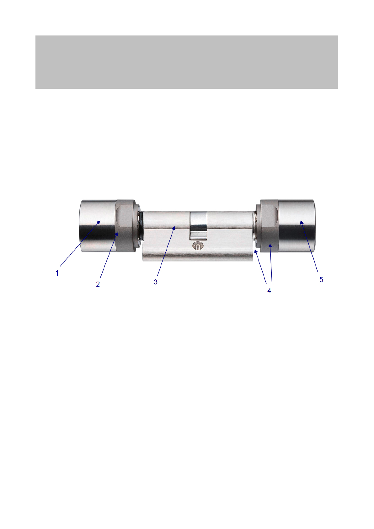
3.2 Locking cylinder design
3 | General information on System 3060
8 / 44
1. Inside thumb-turn
2. Batteries/electronics
3. Actuator
4. Drilling protection
5. Outer thumb-turn
Page 9
SimonsVoss
Manual
Digital Locking Cylinder 3061
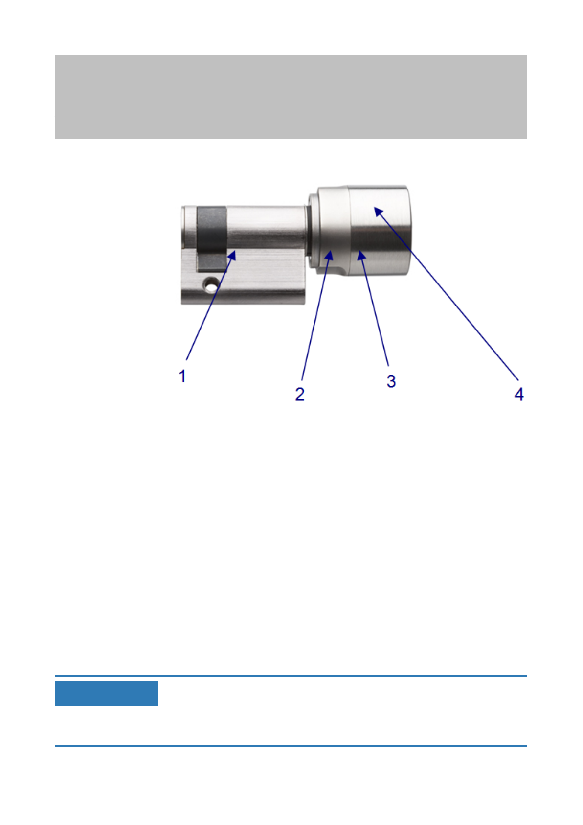
3.3 Half cylinder design
3 | General information on System 3060
9 / 44
1. Actuator
2. Electronics
3. Batteries
4. Thumb-turn
3.4 Opening and locking from the outside
With freely rotating
locking cylinders (FD)
NOTICE
If the user has an ID medium which is not authorised for use at that particular moment due to the time zone plan, a single audible signal will sound.
The cylinder will not engage, so the outer or inside thumb-turn continues to
rotate freely and the user cannot open the door. You need to configure this
response separately in third-party systems.
The outer and inside thumb-turn rotate freely when not activated in
the freely rotating Locking Cylinder, meaning it is not possible to open
or lock the door without a valid ID medium. Identify yourself with your
valid ID medium on the outer thumb-turn to activate the cylinder. If the
ID medium is authorised, an audible signal will sound twice, the blue
LED will flash twice and the locking cylinder will engage ready to
open. Turn the outer thumb-turn in the direction of locking or opening.
You have about five seconds to do so. The engage time can be
configured. A single audible signal will then sound and the outer or
inside thumb-turn will rotate freely again. Ensure that the outside or
inside locking cylinder thumb-turn rotates freely again after the
thumb-turn has been engaged ready for use.
Page 10

SimonsVoss
Manual
Digital Locking Cylinder 3061
3.5 Opening and locking from the inner side
3 | General information on System 3060
10 / 44
With freely rotating
locking cylinders (FD)
With non-freely
rotating locking
cylinders (FD)
The outer and inside thumb-turn rotate freely when not activated in
the freely rotating Locking Cylinder, Doors can also only be opened or
locked on the outside using an ID medium on the inside thumb-turn.
Locking Cylinders which are permanently engaged for use can be
operated from the inside without a ID medium. In this case, the door
can be opened and closed using the inside thumb-turn without an
authorised ID medium.
Page 11

SimonsVoss
Manual
Digital Locking Cylinder 3061
4 System 3060 designs
Different versions of the digital Locking Cylinder are offered to cover the
different needs of the market. The different versions are indicated by a
code. The different versions can be combined:
4 | System 3060 designs
11 / 44
ABBREVIATION DESIGNATION
FD
HZ Half cylinder X
Access control Access Control X X
FH
TS Button control X
MR Multi-point X X
MS Brass version X X
SKG
VDS
AP
CO Comfort cylinder X
WP Waterproof - WP X X
SW Seawater-proof X
WN
SC
VR Shortened range X
DK Detachable knob X
DM Door Monitoring X
Standard (freely
rotating)
Fire-retardant
version
Class AZ VdS
cylinder (basic
protection against
picking)
Class BZ VdS
cylinder (medium
protection against
picking)
Anti-panic
function
Network
integrated
SmartCard
version
LOCKING
CYLINDER
X
X
X
X
X
X X
X
HALF CYLINDER
Refer to the current product catalogue to see which particular versions can
be combined with one another. Locking cylinders are also supplied in
different profiles to satisfy differences in different regions:
PROFILE LOCKING CYLINDER HALF CYLINDER
Page 12

SimonsVoss
Manual
Digital Locking Cylinder 3061
Standard Euro profile
cylinder as per DIN
18252/EN1303
Scandinavian Oval X
British oval X
Swiss Round X X
Locking Cylinders are also offered in mortise and rim cylinder models for
American door profiles.
4.1 FD version (Standard)
Locking Cylinder freely rotating on both sides.
The .FD double thumb-turn cylinder is available from a length of 30-30 mm.
4 | System 3060 designs
X X
12 / 44
4.2 HZ version (Standard)
The standard version of the half cylinder.
4.3
4.4 ZK version
Design is similar to standard version but with access logging and time zone
control.
– Access event logging
The locking cylinder logs up to 3,072 of the most recent access events
with the date, time and transponder ID (TID). The data can be read via
the network using the programming device.
– Time zone control
TLocking Cylinder can be programmed in such a way that authorized
transponders are only authorized for access at specific times. For G1,
there are 5 (+1) time zone groups available per area (e.g. outer
perimeter) within the different time zone schedules while G2 has 100
(+1) such groups.
4.5 version for steel and fire retardant doors
Design is similar to standard version but for doors with sturdy metal
sections, such as fire doors, or doors with highly protective shielding. This
version is recommended in areas with high interference fields, such as
server rooms, and for all metal doors. The FH version cannot be retrofitted.
If wired networks are used, we recommend using this cylinder version due
to its reduced projection.
Before a locking cylinder is installed into a fire/smoke retardant door, the
fire certification has to be checked first to ensure that conformity is in place.
Page 13

SimonsVoss
Manual
Digital Locking Cylinder 3061
It must be ensured that any locking devices or sealing strips do not impede
the orderly operation of the MC.
4.6 TS version
Design as for standard version, but with the additional option of allowing the
cylinder to engage without an identification medium. This cylinder version
can be engaged mechanically with the aid of two buttons on the inside
thumb-turn. This means that no transponder is needed when the user is on
the internal. The cylinder will then engage for five seconds (configurable)
and the door can be opened or locked. Once this time interval expires, the
cylinder rotates freely again on both sides.
The .TS version cannot be retrofit.
4 | System 3060 designs
13 / 44
NOTICE
4.7 MR option
Design is similar to standard version but the locking cam features fixed
points where it positions itself when disengaged. This version is particularly
suitable for very smooth-running locks with multi-point locking systems.
Please observe the lock manufacturer's declaration of conformity when
combining multi-point locks with a panic function.
4.8 MS version
The Locking Cylinder can be supplied with stainless steel or brass colour
finish (highly glossy thumb-turn covers).
4.9 SKG or VdS versions (SZ)
The Locking Cylinder is also available in a VdS cylinder version as an
option. The additional mechanical security features ensure that VdS
Classes AZ and BZ or Class SKG*** are achieved. These versions cannot
be combined with the brass, WP and anti-panic models. The VdS cylinder
can only be supplied in combination with access control (ZK) functions.
The profile cylinder must be protected with a VdS-approved burglar-resistant door plate of class B or C. Such door plates conform to DIN 18257,
Class ES 2 or ES 3. The cylinder may not protrude more than 3 mm above
the door plate. The scope of burglary-resistant measures is based on the
respective national provisions.
This version is available as .MS, .FH and WN versions.
Page 14

SimonsVoss
Manual
Digital Locking Cylinder 3061
4.10 AP version
A cylinder with an anti-panic function must be fitted to all doors where the
lock's panic function may be adversely affected by the position of the cam.
This version contains an integrated spring mechanism which places the
locking cam in a non-critical position, meaning a panic lock's panic function
cannot be blocked.
In contrast to all other cylinders, the .AP type cylinder is fitted the other way
round with the thumb-turn containing the battery and the electronics module
installed on the outside (see diagram).
Unlike the standard anti-panic cylinder (AP), the inside thumb-turn of which
is permanently engaged, the inside thumb-turn for the freely-rotating AP
version (AP.FD) is disengaged mechanically and cannot be engaged with
an identification medium.
4 | System 3060 designs
14 / 44
1. Inside thumb-turn
2. Recessed grip ring
3. Battery replacement key
4. Outside thumb-turn
Page 15

SimonsVoss
Manual
Digital Locking Cylinder 3061
The following aspects should be taken into consideration for doors along
rescue routes which have been installed after April 1, 2003 (exit devices as
per DIN EN 179 or DIN EN 1125): All Locking Cylinder models may be
used for all exit devices where their approval states that the Locking
Cylinder has no impact on the lock's function. The Locking Cylinder
type .AP (anti-panic cylinder) must be used for all exit devices where the
Locking Cylinder cam position affects the lock's function. This must be
stated in the lock manufacturer's approval.
4 | System 3060 designs
15 / 44
DANGER
4.11 AP2 Version
DANGER
Due to the structural design of panic locks, it is not permitted to turn the
Locking Cylinder thumb-turn to the stop position when the door is locked
since this may affect the lock's panic function.
A cylinder with an anti-panic function must be fitted to all doors where the
locking device's panic function may be adversely affected by the position of
the cam. This version contains an integrated spring mechanism which
places the locking cam in a non-critical position, meaning a panic locking
device's panic function cannot be blocked.
You install this version in the same way as a normal Locking Cylinder.
The following aspects should be taken into consideration for doors along
rescue routes which have been installed after April 1, 2003 (exit devices as
per DIN EN 179 or DIN EN 1125): All Locking Cylinder models may be
used for all exit devices where their approval states that the Locking
Cylinder has no impact on the locking device's function. The Locking
Cylinder type .AP2 (anti-panic cylinder) must be used for all exit devices
where the Locking Cylinder cam position affects the locking device's
function. This must be stated in the lock manufacturer's approval.
Due to the structural design of panic locks, it is not permitted to turn the
Locking Cylinder thumb-turn to the stop position when the door is locked
since this may affect the locking device's panic function.
4.12 CO version
In the comfort cylinder (CO), the inside knob is permanently interconnected
with the locking cam, so that doors can be opened and locked from the
inside without needing to use a transponder.
4.13 WP Version (FD)
The protection rating is increased from IP54 to IP66 in the WP version
(weatherproof) of the Locking Cylinder. This version is thus suitable for use
outdoors or on external doors even if the cylinder is not exposed to direct
splash water.
Page 16

SimonsVoss
Manual
Digital Locking Cylinder 3061
Anti-panic cylinder: The WP version is specifically designed for outdoor
areas and should be fitted if the outer thumb-turn comes into contact with
water (e.g. rainwater). The WP version features greater resistance to water,
meaning the cam should not come into contact with water.
This version is available from a length of 30-35 mm and as .FD, .ZK, .MS
and .FH models.
4.14 WP version (HZ/CO/AP)
The electronic thumb-turn is sealed in the WP version of the half, comfort
and anti-panic cylinders, thus providing an increased protection rating of
IP66. This version is thus suitable when the electronics side is outdoors, i.e.
the electronic thumb-turn is exposed to rain, for example. Water must not
enter through the door.
4 | System 3060 designs
16 / 44
4.15 SW version (CO)
The SW (seawater) version of the comfort cylinder has been specially
developed for use on ships or for direct use on the sea. A special, polished
V4A knob and a coated handle component are used on the outside.
4.16 VR version (HZ)
This version features a shortened operating range. It is suitable for use in
items such as locker doors and mail box systems when the distance to the
next door is less than 40 cm.
4.17 DK version (HZ)
The knob can be detached and is ideal for installation behind cover plates
on key switches, for example.
4.18 WN version (HZ)
The WN version is fitted with a network flap (LockNode Inside). This
network cap enables the lock to be networked directly (networked
connection between lock and the LSM).
This version is available for all models.
The network cover can be fitted to locking cylinder types manufactured
after May 2008. This allows such cylinders to be retrofit with a network
connection without a great deal of installation work.
4.19 DM version
The Door Monitoring Cylinder allows the Locking Cylinder to transmit door
events to LSM in real time.
Page 17

SimonsVoss
Manual
Digital Locking Cylinder 3061
4.20 Hybrid-Version
With the hybrid version of the digital locking cylinder, active identification
media (e.g., transponders) and passive identification media (e.g., MIFARE
or DESFire cards) can be used.
4.21 Extra lengths
All double knob cylinders are available with an overall length of up to 140
mm or a maximum of 90 mm on one side. Longer lengths can be supplied
on request. All half cylinders are available with an overall length of up to
100 mm or a maximum of 90 mm on the outside. Longer lengths can be
supplied on request.
4 | System 3060 designs
17 / 44
4.22 Examples of locking cylinder use
FD (ZK) FH (ZK) TS (ZK) AP (ZK)
Entrance doors Fire doors
Apartment
entrance doors
Office doors
Connecting doors
Self-locking doors
*Comply with EN 179 and EN 1125 requirements and the lock
manufacturer's data sheets.
The different versions can be combined as you wish. Exceptions are
indicated in the individual model descriptions.
Aluminium doors Office doors Emergency exits*
Apartment
entrance doors
Anti-panic doors*
Page 18

SimonsVoss
Manual
Digital Locking Cylinder 3061
5 Installation instructions
5.1 General instructions
When installing the digital Locking Cylinder, ensure that there are no
sources of low-frequency radio interference in the surrounding area.
The profile cylinder housing should be fitted flush in outside areas; it should
project a maximum of 3 mm and a profile cylinder escutcheon or security
fitting should be installed if necessary. It is also important to ensure that no
water is able to penetrate the cylinder via the cam section.
You must not strike the thumb-turns when installing the cylinder.
All thumb-turns are locked into place with a bayonet mount (exception: antipanic inside knob and SKG/VdS outside knob).
The inner side of the Locking Cylinder is laser-engraved with (the letters IL
for inside length) on the profile cylinder housing; the electronics side is
identifiable by the black plastic ring between the thumb-turn and the profile
cylinder housing.
Batteries are already installed before delivery.
All the tasks listed in this section can also be carried out using the
installation/battery key.
5 | Installation instructions
18 / 44
5.2 Programming the locking cylinder
Both the digital Locking Cylinder and the associated transponder must be
programmed before installation. You can find more detailed information in
the software operation instructions.
Page 19

SimonsVoss
Manual
Digital Locking Cylinder 3061
5.3 Installation variants
5.3.1 Installation of double thumb-turn cylinders (except types .AP/.SKG/.VdS)
5 | Installation instructions
19 / 44
NOTICE
1. Installation key
2. Side marking
3. Recessed grip ring
4. Inside thumb-turn
5. Battery replacement key
6. Locking disc with opening (identical on outside)
7. Outer thumb-turn
5.3.1.1 Removing the outer thumb-turn
Place the installation key on the outer thumb-turn in such a way that its two
teeth engage into the outer thumb-turn; if necessary, turn the thumb-turn
until both teeth lock into the locking disc.
The installation tool must be placed flat on the internal front surface of the
thumb-turn to ensure that the tool can lock into the locking disc.
Hold the outer thumb-turn firmly and carefully turn the installation tool about
30° in a clockwise direction (until you hear a click). Remove the thumb-turn.
Page 20

SimonsVoss
Manual
Digital Locking Cylinder 3061
5.3.1.2 Fastening the digital cylinder into the locking device
Turn the cam until it is vertical and pointing downwards. Insert the digital
locking cylinder through the locking device in such a way that the inside
thumb-turn (see diagram above) is facing the inner side of the door. Fasten
the cylinder into the mortise lock with the fastening screw.
5 | Installation instructions
20 / 44
NOTICE
NOTICE
You must not strike the thumb-turns when installing the cylinder. Do not allow the cylinder to come into contact with oil, grease, paint or acids.
5.3.1.3 Fastening the outer thumb-turn
Replace the thumb-turn and turn in an anti-clockwise direction while
applying slight pressure until the outer thumb-turn grips into the indents in
the flange. Possibly place the thumb-turn in this position by pressing it
towards the profile cylinder housing.
Turning the bayonet disc when not installed may prevent the thumb-turn
from being fastened into position. In such a case, push the disc back into
the original 'bayonet disc open' position using the installation tool. (see diagrams)
1. Bayonet disc
2. Thumb-turn
3. Bayonet disc closed
4. Bayonet disc open
Page 21

SimonsVoss
Manual
Digital Locking Cylinder 3061
Place the installation key on the outer thumb-turn in such a way that its two
teeth engage into the outer thumb-turn (if necessary, turn the thumb-turn
until both teeth lock into the locking disc). Lock the thumb-turn into position
again by rotating it 30° in a clockwise direction.
5.3.1.4 Carry out a functional test
1. Engage cylinder using a valid ID medium and turn the thumb-turn in
both the locking and opening direction with the door open. The thumbturn must be able to rotate easily when you do so.
2. Close the door and repeat the process. If the locking cylinder should be
stiff, you need to align the door or modify the strike plate.
5.3.2 Fitting an anti-panic cylinder
5 | Installation instructions
21 / 44
1. Inside thumb-turn
2. Recessed grip ring
3. Battery replacement key
4. Outside thumb-turn
Page 22

SimonsVoss
Manual
Digital Locking Cylinder 3061
The locking cam is always in a pre-defined position in the AP cylinder when
disengaged. This prevents accidental blocking. Unlike other cylinder
versions, the AP cylinder is installed the other way round (inserted into the
lock from the inside to the outside).
5.3.2.1 Removing the inside thumb-turn
Loosen the inside thumb-turn's threaded pin (see diagram above) using an
Allen key. Do not unscrew completely. Hold the cam firmly and then turn
the inside thumb-turn anti-clockwise or, in the case of a freely rotating AP
cylinder, remove the thumb-turn after loosening the threaded pin.
5.3.2.2 Fastening the digital cylinder into the locking device
Turn the cam until it is vertical and pointing downwards. Insert the digital
locking cylinder through the locking device from the outside in such a way
that the outer thumb-turn is facing the outer side of the door. Fasten the
cylinder into the mortise lock with the fastening screw.
5 | Installation instructions
22 / 44
NOTICE
You must not strike the thumb-turns when installing the cylinder. Do not allow the cylinder to come into contact with oil, paint or acids.
5.3.2.3 Fastening the inside thumb-turn
Screw the inside thumb-turn onto the thread until it locks into place as it
comes up against the cam. Pull on the inside thumb-turn, or push on the
inside thumb-turn of a freely rotating AP cylinder, until it locks into position.
Fasten the threaded pin tightly using the Allen key.
5.3.2.4 Functional test
– To verify that the AP2 cylinder functions correctly in an anti-panic lock,
you must check that the cam moves easily and that the door opens
correctly using the procedure described below.
– Carry out the functional test in the direction of escape.
– You must carry out a functional test whenever the cylinder or the
fastening screw is repositioned.
– You will need an authorised identification medium to carry out the
functional test.
– Withdraw the dead bolt before the functional test.
Page 23

SimonsVoss
Manual
Digital Locking Cylinder 3061
5 | Installation instructions
23 / 44
U section: No restore force on the cam
R section: Restore force section towards U section
O section:
OG: Top threshold section
UG: Lower threshold section
1: Thumb-turn
2: Cam position (concealed)
1. With the cylinder engaged, first turn the thumb-turn in the direction of
locking as far as the deadbolt throw in the 'R' section.
ð You will feel the restore force. When you release the thumb-turn in
this position, it must turn back to the 'U' section of its own accord.
2. Lock the locking device and check the restore force. To do so, turn the
engaged thumb-turn in the direction of locking through the 'R' section
and into the 'O' section.
ð The dead bolt extends. There is no restore force in the 'O' section.
3. Move the thumb-turn slightly over the threshold between the 'O' and
'R' section in the same direction of rotation.
ð The dead bolt will extend. The restore force must turn the thumb-
turn automatically from this point as far as the 'U' section if it is
released.
ð If the thumb-turn does not automatically rotate as far as the 'U'
section, either the fastening screw has been tightened too firmly or
the locking device has been aligned incorrectly. The test is to be
repeated after the fault has been eliminated. A fastening screw
which has been tightened too firmly acts as a brake on the restoring
force mechanism.
Top dead point in deadbolt throw - no restore force on
the cam
Page 24

SimonsVoss
Manual
Digital Locking Cylinder 3061
4. Lock the door and check that the locking device functions correctly by
pressing the door fitting or panic bar in the direction of escape.
ð The dead bolt must spring back and it must be possible to open the
door easily.
ð If the dead bolt does not draw back when the handle is turned or the
door fitting catches, either the locking cylinder or the locking device
is incorrectly aligned or defective. The test is to be repeated after the
fault has been eliminated as described above.
If you cannot ensure that the locking device will function correctly after the
functional test, please contact the SimonsVoss hotline.
5.3.3 Installation of SKG/VdS cylinders
Loosen the outside knob's threaded pin using an Allen key. Do not unscrew
completely. Hold the inside knob firmly and then turn the outside knob anticlockwise.
Turn the cam until it is vertical and pointing downwards. Insert the digital
locking cylinder through the lock from the inner side. Fasten the cylinder
into the mortise lock with the fastening screw. Then screw the outside knob
back into position on the cylinder and tighten the threaded pin.
5 | Installation instructions
24 / 44
NOTICE
5.3.3.1 Installation of core extraction protection adapters (Z4.KA.SET)
The core extraction protection adapter (Z4.KA.SET) is compatible with all
SKG/VdS cylinders manufactured up to 2010 and all .FD cylinders.
Instructions:
1. Disassemble the non-electronic knob.
2. Remove the rubber seal on the tip of the outside tube.
3. Place the core extraction protection adapter on the outside tube and
turn while applying a little pressure, so that it grips into the indents on
the flange (in a similar way to the knob when installed). The openings
in the adapter and the outside tube web must align.
4. Insert the supplied screw through the lock and tighten carefully.
5. Replace the knob and turn in an anti-clockwise direction while applying
slight pressure until the outer knob grips into the indents in the flange.
Possibly place the knob in this position by pressing it gently towards
the profile cylinder housing.
Turning the bayonet disc when not installed may prevent the thumb-turn
from being fastened into position. In such a case, push the disc back into
the original 'bayonet disc open' position using the installation tool.
Page 25

SimonsVoss
Manual
Digital Locking Cylinder 3061
6. Place the installation key on the outside thumb-turn in such a way that
its two teeth engage into the outside thumb-turn (if necessary, turn the
thumb-turn until both teeth lock into the locking disc). Lock the thumbturn into position again by rotating it 30° in a clockwise direction.
5.3.3.2 Installation of core extraction protection adapters (Z4.KA.SET2)
The core extraction protection adapter (Z4.KA.SET2) is compatible with all
SKG/VdS cylinders manufactured from 2011 onwards.
Instructions:
1. Disassemble the non-electronic knob.
2. Then screw the core extraction protection adapter into position on the
cylinder and lock into place using the threaded pins.
3. Install the non-electronic knob on the core extraction protection
adapter.
An elongated version of the adapter is available for the Italian market.
(Z4.KA.SET2.IT).
5 | Installation instructions
25 / 44
5.3.4 Half Cylinder DK/MR
The thumb-turn, including the inside tube, can be removed from the
cylinder housing to install the DK and MR versions. The procedure is
described below. It is only necessary for key switches, for example, if the
half cylinder cannot be installed using the fastening screw.
5.3.4.1 Disassembly
Page 26

SimonsVoss
Manual
Digital Locking Cylinder 3061
If you need to disassemble the half cylinder, please proceed as follows:
1. Using a tool such as a screwdriver, grip into the two slots in the plastic
disc between the thumb-turn and the profile cylinder housing and turn
the tool while applying a little pressure. This breaks the disc.
2. Remove the remains of the plastic disc.
3. Engage the half cylinder using an authorised ID medium.
4. While the thumb-turn is engaged, turn it anti-clockwise until it will turn
no more (e.g. towards the lock when installed or holding the cam with
your hand when not installed; see Step A in the diagram).
5. Press thumb-turn towards profile cylinder housing until it stops (you
will hear it click. If necessary, move thumb-turn backwards and
forwards several times until you hear a click; see Step B and D in the
diagram).
6. If needed, engage the half cylinder once more using an authorised ID
medium.
7. While the thumb-turn is engaged, turn it anti-clockwise and apply
pressure against the stop position (see Step B and D in the diagram).
8. While applying pressure, pull the thumb-turn (including inside tube)
from the profile cylinder (see Step D in the diagram).
5 | Installation instructions
26 / 44
NOTICE
NOTICE
NOTICE
You must not strike the thumb-turn during installation. Do not allow the cylinder to come into contact with oil, paint or acids.
5.3.4.2 Installation
1. Remove the metal discs on the inside tube and push a plastic disc
onto it instead. You will find the plastic disc in the supplied package.
2. Push the removed metal discs onto the inside tube, so that a plastic
disc and a varying number of metal discs, depending on the half
cylinder type, are on the inner tube.
3. Push the inner tube thumb-turn into the profile cylinder housing until it
stops.
4. Engage cylinder using an authorised ID medium.
5. While the thumb-turn is engaged, press it gently against the profile
cylinder housing while turning clockwise at the same time until the
inside tube clicks into place in the profile cylinder housing.
Check that it has locked into position correctly by pulling the thumb-turn
gently while turning it backwards and forwards.
You will find the required plastic discs in the supplied package.
Page 27

SimonsVoss
Manual
Digital Locking Cylinder 3061
When installing, ensure that only one plastic disc and the same number of
metal discs are on the inner tube as when you took it apart. The plastic disc
must be placed directly on the thumb-turn.
5.3.4.3 Functions test
1. Engage half cylinder using a valid ID medium and turn the thumb-turn
in the locking and opening direction with the door open. The thumbturn must be able to rotate easily when you do so.
2. Close the door and repeat the process. If the half cylinder should be
stiff, you need to align the door or modify the strike plate.
This generally also applies when installing the cylinder in a key switch, for
example.
5 | Installation instructions
27 / 44
5.3.5 Installing Swiss Round
Both cylinders and a fitting need to be removed from doors when installing
a Swiss round cylinder.
The inside thumb-turn is removed and re-fitted in the same way as Half
Cylinder DK / MR.
The outside knob is removed and re-fitted in the same way as the outside
knob on a VdS cylinder.
1. Disassemble inside thumb-turn and outside thumb-turn. Remove a
fitting from the door.
2. Push cylinder into the profile and fasten with the fastening screw.
3. Fit inside thumb-turn and outside thumb-turn. Mount fitting again.
Page 28

SimonsVoss
Manual
Digital Locking Cylinder 3061
6 System 3060 audible signals
The Locking Cylinder emits an audible signal to indicate its status and an
authorisation. The table below lists what the audible signals mean.
2 short audible signals
before engaging and a
short tone after
disengaging.
1 short audible signal:
cylinder does not
engage.
Battery Warning Level
1: 8 short audible
signals before engaging.
Battery Warning Level
2: 8 short audible
signals 30 seconds long
with one second pause
each time before
engaging.
Freeze mode (G2 only):
6 audible signals (long –
pause – short).
8 short audible signals
after disengaging.
6 | System 3060 audible signals
Normal activation None
Attempted entry with a
transponder listed in the
locking system, but:
– used outside time
zone.
– Activated alarm
system while using
the SimonsVoss
Block Lock.
Batteries are low.
Batteries are almost
completely empty.
Battery empty. Cylinder
can no longer be
opened using an
authorised transponder.
Cylinder can only be
engaged using a battery
replacement
transponder.
Transponder battery is
low.
None
Replace batteries in the
cylinder.
Replace batteries in the
cylinder immediately.
Replace batteries and
reset with a battery
replacement
transponder.
Have transponder
battery replaced.
28 / 44
6.1 Battery warnings
A battery management system has been implemented in locking cylinders
and transponders which warns the user in good time that the battery
capacity is diminished. This prevents the batteries from becoming fully
discharged. The individual battery warning levels are described below.
The locking cylinder batteries feature a redundant system. If one of the
batteries fails or its capacity falls below a certain level, the system emits a
battery warning.
Page 29

SimonsVoss
Manual
Digital Locking Cylinder 3061
The battery warning levels between G1 and G2 differ after Battery Warning
Level 2 if the battery capacity falls under the emergency battery warning
threshold values.
– Warning Level 1: Low batteries
If the charged capacity falls below 25% in one of the batteries, Battery
Warning Level 1 is activated. After you activate the transponder, you will
hear eight brief audible signals in rapid succession before the cylinder
engages. You must replace the batteries.
– Warning Level 2: Extremely low batteries
If the locking cylinder batteries discharge even further, short audible
signals are heard in rapid succession for about 30 seconds before the
cylinder engages after the transponder is activated. The cylinder does
not engage until the audible signals have finished. The batteries should
be replaced as quickly as possible.
If this warning level is ignored, the locking cylinder switches to what is
known as storage or freeze mode.
– Emergency battery – Storage mode (G1 cylinders):
In storage mode, the cylinder can only be opened with the aid of a
programming device (Smart CD).
– Emergency battery – Freeze mode (G2 cylinders):
In freeze mode, an audible signal will sound if an attempt is made to
open using an authorised transponder (Section ), but the cylinder will
not engage.
The G2 cylinder can now only be opened using a battery replacement
transponder or programming device.
– Active locking devices: The system administrator can use a G2
battery replacement transponder (freeze mode transponder) for
about 30 seconds to eliminate freeze mode and open the door with
a user transponder to replace the batteries.
– SmartCard locking devices: The system administrator can use a G2
battery replacement transponder (freeze mode transponder) to
permanently eliminate freeze mode (including warning levels) and
open the door with a user transponder to replace the batteries.
6 | System 3060 audible signals
29 / 44
NOTICE
After using the "2 battery replacement transponder"on SC locks, you must
change the batteries immediately; if not, the batteries may discharge completely without any further warnings.
Active cylinder:
WARNING
LEVEL 1
8 short audible
signals before
engaging
WARNING
LEVEL 2
30 seconds long
with one second
pause each time
before engaging
FREEZE MODE
6 audible signals
(long – pause –
short)
Page 30

SimonsVoss
Manual
Digital Locking Cylinder 3061
6 | System 3060 audible signals
30 / 44
Battery change:
activate with
battery
replacement
transponder
6 audible signals
(long – pause –
short)
LED flashes red
once and blue
once
Battery change:
activate with
battery
replacement
transponder
Cylinder SC
(transponder
use):
Cylinder SC
(SmartCard use):
Up to 15,000
access events or
up to 9 months on
standby
8 short audible
signals before
engaging
LED flashes red
briefly 8 times
before engaging
Up to 300 access
events or up to 30
days
Up to 50 access
events or up to 30
days
30 seconds long
with one second
pause each time
before engaging
LED flashes red
briefly twice for 30
seconds before
engaging
Up to 200 access
events or up to 20
days
6.2 Battery warning for transponders
When the transponder battery is low, short audible signals are heard in
rapid succession on the locking cylinder (not the transponder) after the
locking cylinder disengages each time the transponder is used.
Page 31

SimonsVoss
Manual
Digital Locking Cylinder 3061
7 System 3060 battery replacement
7.1 General instructions
Only trained personnel may replace the batteries.
You must wear clean gloves made of cloth and free of fat or grease when
replacing the batteries to prevent the batteries being contaminated by
fingerprints. Fingerprints on batteries may reduce battery life considerably.
Only use batteries which have been approved by SimonsVoss.
7 | System 3060 battery replacement
31 / 44
NOTICE
NOTICE
You may cause damage to the Locking Cylinder if you reverse the polarity.
The batteries used in this device may pose a fire or burn hazard if handled
incorrectly. Do not recharge, open or burn batteries, or heat them to over
100° C.
Dispose of lithium batteries properly immediately after they have discharged. Store them out of children's reach; do not open and do not throw
into a fire. Always replace both batteries when changing batteries. Please
note safety instructions.
The locking cylinder retains its status, programming and saved protocols
even without power supply.
7.2 Battery life
Battery life is different for each locking cylinder version as power
consumption varies when the cylinder is activated or a data connection is
established.
VERSION BATTERY LIFE
Standard cylinder
and versions
WN (LNI /
LockNode)
Up to 10 years Up to 300,000 2
Up to 5 years Up to 150,000 2
NUMBER OF
ACTIVATIONS
NUMBER OF
BATTERIES
The specified battery life is for guidance only. A battery warning is not
emitted when the aforementioned battery life expires, but is based on the
measured battery status instead.
7.3 Emergency battery procedure
As stated above, a locking cylinder changes to storage mode (G1) or freeze
mode (G2) if Battery Warning Level 2 is ignored. A different procedure is
used each for G1 and G2 to eliminate this mode.
Page 32

SimonsVoss
Manual
Digital Locking Cylinder 3061
7.3.1 Storage mode (G1)
If the locking cylinder is in emergency battery storage mode, proceed as
follows to open the door to change the battery and reset the cylinder.
1. Take notebook or PDA (import locking plan beforehand) and
programming device to the door in question.
2. Select the corresponding lock from the locking plan.
3. Re-programme locking cylinder without making any modifications. This
eliminates the battery warning and storage mode.
4. Engage the locking cylinder using an authorised transponder and open
the door. The cylinder will immediately revert to storage mode, as both
batteries are almost empty.
5. Renew batteries (see below).
6. Re-programme locking cylinder without making any modifications. This
eliminates the battery warning check marks and storage mode.
7. Engage the locking cylinder using an authorised transponder.
After battery replacement, the locking cylinder signals Warning Level 2
again. The locking cylinder's electronics then detect that the batteries are
fully charged or have been replaced and the cylinder is available for normal
use again.
7 | System 3060 battery replacement
32 / 44
NOTICE
7.3.2 Freeze mode (G2)
Emergency opening of the door and elimination of emergency retention
mode in G2 is easier than G1 generation systems.
1. Programme the G2 battery replacement transponder if necessary.
2. Deactivate freeze mode using the G2 battery replacement
transponder.
3. Use an authorised transponder to engage the locking cylinder and
open the door.
4. Replace the battery.
5. Deactivate freeze mode using the G2 battery replacement
transponder.
6. Perform an opening transaction on the locking cylinder with an
authorised transponder to test that it is functioning and eliminate
freeze mode.
Only use the G2 battery replacement transponder to deactivate freeze
mode and then immediately replace the cylinder batteries. Misuse may lead
to complete battery discharge and, consequently, a complete failure of the
cylinder.
Page 33

SimonsVoss
Manual
Digital Locking Cylinder 3061
7.4 Procedure
1. Place the installation/battery key on the inside thumb-turn in such a
way that the two teeth lock into the openings in the locking disc; if
necessary, turn the thumb-turn until both teeth engage into the locking
disc.
7 | System 3060 battery replacement
33 / 44
NOTICE
The tool must be placed flat on the inside front surface of the recessed grip
ring to ensure that the installation/battery key can engage into the locking
disc.
2. Hold the inside thumb-turn firmly and carefully turn the installation/
battery key about 30° in a clockwise direction (until you hear a click).
3. Remove installation/battery key from the thumb-turn.
4. Push recessed grip ring backwards towards the door, so that it comes
away from the thumb-turn.
5. Hold recessed grip ring firmly and turn thumb-turn about 10° in an anticlockwise direction and remove.
6. For MH cylinders only: Carefully fold antenna upwards.
7. Carefully remove both batteries from the holder.
8. Insert the new batteries into the holder at the same time with the
positive poles next to each other; change the batteries as quickly as
possible. Use clean gloves free of fat or grease to handle new
batteries.
Page 34

SimonsVoss
Manual
Digital Locking Cylinder 3061
7 | System 3060 battery replacement
34 / 44
9. For MH cylinders only: Lock antenna back into place.
10. Replace the thumb-turn (align the triangle mark as in the diagram),
hold the recessed grip ring firmly and fasten the inside thumb-turn by
turning in a clockwise direction (about 10°). (Diagram may differ
slightly from the purchased product)
11. Push recessed grip ring back onto the thumb-turn, so that the thumbturn and ring close together in a flush fit.
12. Place the installation/battery key on the inside thumb-turn in such a
way that the two teeth lock into the openings in the locking disc; if
necessary, turn the thumb-turn until both teeth engage into the locking
disc.
13. Close the thumb-turn again by turning it about 30° in a clockwise
direction (until you hear a click).
Then activate an authorised ID medium and check that it functions.
7.5 Procedure for outer thumb turn (MH cylinder)
4 batteries are built into the MH cylinder: 2 in the inside thumb-turn, 2 in the
outer thumb-turn.
Proceed as follows to replace the two batteries:
Page 35

SimonsVoss
Manual
Digital Locking Cylinder 3061
1. Use the battery replacement key to detach the outer thumb-turn. To do
so, face the outer thumb-turn and place the battery replacement key
on the bayonet mount and turn in a clockwise direction until you can
remove the thumb-turn easily.
ð The outer thumb-turn is now fully detached.
2. Place the battery replacement key on the detached thumb-turn again
and open the bayonet mount completely ( turn in an anti-clockwise
direction as you face the mount). You may be able to skip this step.
ð The lid springs open by itself as the bayonet mount is unscrewed.
3. Carefully lift off the lid.
ð The lid is attached to the thumb-turn with a small securing strap and
a ribbon cable; the batteries are now exposed.
4. Insert new batteries in such a way that the two plus poles lie flat on
one another and then position in the thumb-turn.
7 | System 3060 battery replacement
35 / 44
NOTICE
NOTICE
You should always replace both batteries with new ones when changing
the batteries.
You must place the ribbon cable loop crossways directly under the thumbturn lid.
5. Reattach lid to the outer thumb-turn and press gently.
ð The lid is now flush against the outer thumb-turn.
6. Use the battery replacement key to lock the bayonet mount to a
minimum extent until the lid locks into the outer lid of its own accord.
(about 1° in a clockwise direction)
7. Re-attach outer thumb-turn onto the locking cylinder.
ð The outer thumb-turn is now flush against the locking cylinder.
8. Now use the battery replacement key to lock the bayonet mount
completely. To do so, face the outer thumb-turn and place the battery
replacement key on the bayonet mount and turn in an anti-clockwise
direction until the thumb-turn is firmly in position.
9. Check that the outer thumb-turn is firmly attached again and test the
locking cylinder function to ensure that it works.
Page 36

SimonsVoss
Manual
Digital Locking Cylinder 3061
8 Maintenance, cleaning and disinfection
8 | Maintenance, cleaning and disinfection
36 / 44
NOTICE
NOTICE
NOTICE
Digital locking cylinders MUST not come into contact with oil, grease, paint
or acids.
The use of unsuitable or aggressive disinfectants can damage the locking
cylinder.
Clean the locking cylinder if necessary with a soft, moist cloth.
Only use disinfectants explicitly suitable for the disinfection of sensitive
metal surfaces and plastic.
HZ.SL:it is recommended to grease the latching edge on the electrical enclosure lever handle.
Empty batteries always must be replaced by new ones approved for use by
SimonsVoss. Dispose of old batteries in the proper manner.
Carry out a new functional test after changing the batteries in anti-panic
cylinders.
Page 37

SimonsVoss
Manual
Digital Locking Cylinder 3061
9 Areas of use
9.1 General
The digital locking cylinder is compatible with locks for Euro profile cylinder
as per DIN 18252 and EN1303.
9.2 Fire doors
As a general rule, this cylinder can be fitted into fire doors. However, you
must check that it is actually approved for use in fire doors.
9.3 Doors along rescue routes
9 | Areas of use
37 / 44
Type .AP should be installed for use in doors with an anti-panic function in
which the position of the cam may have an effect on the lock's functioning.
This must be specified in the lock manufacturer's approval. Also see
industrial standards EN 179 and EN 1125 and the individual lock
manufacturers' data sheets.
9.4 Installation outdoors
If you are unable to ensure that no water will come through the door, we
recommend using the respective .WP versions. The outer thumb-turn is
completely sealed in the anti-panic cylinder model and the whole cylinder is
sealed in the double thumb-turn cylinder variant.
Page 38

SimonsVoss
Manual
Digital Locking Cylinder 3061
10 Accessories
10.1 Thumb-turns
The following special thumb-turns are available as accessories:
– Outer thumb-turn in a TN4 design
– Outer thumb-turn, 42 mm in diameter with recessed grips
– Inside thumb-turn, 36 mm in diameter for a .TS cylinder
– Outer thumb-turn, shortened
– Brass thumb-turn, matt (inside and outer thumb-turn)
These thumb-turns can replace the original locking cylinder thumb-turns at
any time. See Installation instructions or Battery replacement for thumb-turn
installation.
10 | Accessories
38 / 44
10.2 Core extraction protection adapter (Z4.KA.SET)
This adapter is compatible with all SKG/VdS cylinders manufactured up to
2010 and all .FD cylinders.
There is a mechanical extension for core extraction protection fittings as the
profile cylinder profile is not cut out of these fittings. The extension is 8 mm
long and can be retrofitted at any time.
10.3 Core extraction protection extension for SKG/VdS cylinders (Z4.KA.SET2)
This adapter is compatible with all SKG/VdS cylinders manufactured in
2011 and onwards.
There is a mechanical extension for core extraction protection fittings as the
profile cylinder profile is not cut out of these fittings. The extension is 8 mm
long and can be retrofitted at any time.
10.4 Core extraction protection extension for SKG/VdS cylinders (Z4.KA.SET2.IT)
This adapter is compatible with all SKG/VdS cylinders manufactured in
2011 and onwards.
There is a mechanical extension for core extraction protection fittings as the
profile cylinder profile is not cut out of these fittings. The extension length is
16 mm for special Italian escutcheons and can be retrofitted at any time.
10.5 Tool
In addition to the installation tool, a battery replacement key is also included
in the supply package. You can use this tool to install or remove outer
thumb-turns and replace batteries.
Page 39

SimonsVoss
Manual
Digital Locking Cylinder 3061
10.6 Battery set
A new set of batteries can be ordered, which contains ten CR2450
batteries. Only ever use batteries approved by SimonsVoss.
10 | Accessories
39 / 44
Page 40

SimonsVoss
Manual
Digital Locking Cylinder 3061
11 Data sheets
11.1 Locking cylinder
11 | Data sheets
40 / 44
Profile cylinder
Batteries
Ambient conditions
Features
Basic length:
Installation lengths in 5mm increments, overall length up to 140 mm
(max. 90mm on one side); special lengths on request.
Type: CR, 2450, 3V
Manufacturer: Sony, Panasonic, Varta
Quantity: 2 units
Battery life:
Operating temperature: -25°C to +65°C
Storage temperature: -35°C to +65°C
Protection class:
Air humidity: <95%: non-condensing
– 3,000 access events can be logged (ZK)
– Network-ready with integrated LockNode (WN)
– LockNode can be retrofitted
– Time zone groups: G1: 5 / G2: 100
– Max. number of transponders per G1 Cylinder: 8000 / G2: 64,000
– Different permanent/open modes
Outside 30 mm, internal 30 mm
(AP/WP 35mm)
up to 300,000 lock operations or
up to 10 years on standby
Standard protection rating IP54
(when installed); .WP variant:
IP66
Thumb-turns
FH cylinder thumbturns
Material: Stainless steel
Colours: Stainless steel, brushed
Diameter: 30 mm
Length:
Material:
Colours:
Diameter: 30 mm
37 mm (from front surface of
profile)
Inside thumb-turn: stainless steel
cover; recessed grip: plastic;
outer thumb-turn: identical to
standard cylinders
Cover: brushed stainless steel;
recessed grip: black; outside
thumb-turn identical to standard
cylinders
Page 41

SimonsVoss
Manual
Digital Locking Cylinder 3061
11 | Data sheets
41 / 44
AP cylinder thumbturns
MS cylinder thumbturns
Length:
Material:
Colours:
Diameter: 30 mm
Length:
Material:
Colours:
Diameter: 30 mm
Length:
37 mm (from front surface of
profile)
Outside thumb-turn: identical to
standard cylinders: Aluminium
Outside thumb-turn: Brushed
stainless steel; internal thumbturn: Nickel-coated aluminium
Outside: 37 mm (from front
surface of profile); internal: about
36 mm (from front surface of
profile)
Outside thumb-turn: identical to
standard cylinders; internal
thumb-turn: identical to standard
cylinders
Outside thumb-turn: Cover made
of high-gloss brass; recessed
grip: matt brass: internal thumbturn: Cover made of high-gloss
brass; recessed grip: Matt brass
Outside: 37 mm (from front
surface of profile)
Thumb-turns
Profile cylinder
Batteries
11.2 Half cylinder
Material: Stainless steel
Colours: Stainless steel, brushed
Diameter: 30 mm
Length:
Basic length: outside 30 mm, internal 10 mm
Installation lengths in 5mm increments (no installation kit) an overall
length of up to 100 mm with a maximum length of 90 mm on the outer
side of the cylinder. Greater lengths on request.
Type: CR, 2450, 3V
Manufacturer: Sony, Panasonic, Varta
Quantity: 2 units
Battery life:
37 mm (from front surface of
profile)
up to 300,000 lock operations or
up to 10 years on standby
Page 42

SimonsVoss
Manual
Digital Locking Cylinder 3061
11 | Data sheets
42 / 44
Features
Ambient conditions
Cam HZ.SL
– 3,000 access events can be logged (ZK)
– Network-ready with integrated LockNode (WN)
– LockNode can be retrofitted
– Time zone groups: G1: 5 / G2: 100
– Max. number of transponders per G1 Cylinder: 8000 / G2: 64,000
– Different permanent/open modes
Operating temperature: -25°C to +65°C
Storage temperature: -35°C to +65°C
Standard protection rating IP54
Protection class:
Air humidity: <95%: non-condensing
Cam position handle: 37°
Cam width from neutral position: 11 mm
(when installed); .WP variant:
IP66 thumb-turn
Page 43

SimonsVoss
Manual
Digital Locking Cylinder 3061
12 Declaration of conformity
You can access documents such as declarations of conformity and other
certificates online at www.simons-voss.com.
12 | Declaration of conformity
43 / 44
Page 44

SimonsVoss
Manual
Digital Locking Cylinder 3061
13 Help & Contact
13 | Help & Contact
44 / 44
Instruction manuals
Hotline
Email
FAQs
You will find detailed information on operation and configuration
online under INFOCENTER > DOWNLOADS on our homepage at
www.simons-voss.de
If you have any questions, the SimonsVoss Service Hotline will be
happy to help you on +49 (0)89 99 228 333 (German fixed network;
call charges vary, depending on the operator)
You may prefer to send us an email.
hotline@simons-voss.com
You will find information and help for SimonsVoss products in the
FAQs section under INFO CENTRE > FAQ SECTION at
www.simons-voss.de
SimonsVoss Technologies GmbH, Feringastrasse 4, 85774
Unterföhring, Germany
 Loading...