

Page 1

MANUAL
PIN CODE KEYPAD 3068
February 2013
Page 2

MANUAL
PIN CODE KEYPAD 3068
2
1.0.
General information 4
1.1 Safety Remarks__________________________________________ 4
1.2 Product Description ______________________________________ 5
2.0 Functional Overview 5
2.1 Function Overview _______________________________________ 5
2.2 Operating modes ________________________________________ 6
2.3 Operating_______________________________________________ 6
3.0 Start-up 7
4.0 Programming PINs 8
4.1 First Start-up ____________________________________________ 8
4.2 Programming Additional PINs______________________________ 8
4.3 Procedure ______________________________________________ 9
5.0 Deleting PINs 9
5.1 Description _____________________________________________ 9
5.2 Procedure _____________________________________________ 10
6.0 Programming the Transponder Data Records with the 10
6.1 Assignment of PINs and Transponders _____________________ 10
6.2 Description ____________________________________________ 11
6.3 Procedure _____________________________________________ 12
7.0 Reading out Transponders 12
7.1 Description ____________________________________________ 12
7.2 Procedure _____________________________________________ 12
8.0 Resetting Transponders 13
8.1 Description ____________________________________________ 13
8.2 Procedure _____________________________________________ 13
9.0 Opening 14
10.0 Meaning of the LED 14
11.0 Battery Warning 15
12.0 Battery Replacement 15
Page 3

MANUAL
PIN CODE KEYPAD 3068
3
13.0 Special Functions 17
13.1 Hidden Lock for SimonsVoss VdS Shuntlock 3066 ___________ 17
13.2 Miscellaneous __________________________________________ 18
14.0 Technical Specification 18
Page 4

MANUAL
PIN CODE KEYPAD 3068
4
1.0. General information
Please take 15 minutes and read through these Instructions
in order to familiarise yourself with the function of your PinCode Keypad.
1.1 Safety Remarks
Caution! Incorrect handling of the batteries used in this product can result in the risk
of fire or burns. Do not charge, open or burn these batteries or heat them to more
than 100° C (212° F).
Make sure that the PinCode Keypad remains free of dirt and scratches; do not drop
the Keypad or otherwise subject it to heavy impacts.
Furthermore, please note that you should program the Keypad with a PIN code immediately after you start it up.
Use of a SimonsVoss PinCode Keypad requires knowledge of the use of the product
and of the SimonsVoss software. For this reason, only trained and authorised personnel should program the PinCode Keypad.
SimonsVoss Technologies AG will not accept any liability for damages caused by incorrect programming.
If the PinCode Keypad is incorrectly programmed or is defective, access through a
door may be blocked. SimonsVoss AG is not liable for the consequences, such as
blocked access to injured or endangered persons, property damage or other damages.
The casing of the PinCode keypad is secured with two Torx screws (TX6) for increased security against unauthorised opening.
Page 5

MANUAL
PIN CODE KEYPAD 3068
5
1.2 Product Description
The PinCode Keypad 3068 is a digital "key" (transponder), which opens SimonsVoss
lockings without contact via radio transmission after the correct numerical codes are
entered.
To configure the system, you must first correctly configure at least one PIN and the
associated integrated transponder for the locking. The associated locking is then released after a correct PIN has been entered.
The PinCode Keypad that you have purchased is a product that can be used both inside and out. The product has its own power supply, so that it can be operated completely self-sufficiently. Installation is very simple, because absolutely no cabling is
required.
Because of the modularity, this component can be seamlessly integrated into the SimonsVoss System 3060, and, like all SimonsVoss components (on the transponder
side), it can be programmed with the locking plan software.
2.0 Functional Overview
2.1 Function Overview
The PinCode Keypad comprises the following components:
• PIN code input and evaluation
• Integrated digital key (transponder), which opens the associated locking when
it is triggered after the PIN code has been evaluated successfully
Consequently, the PinCode Keypad allows you to address all SimonsVoss lockings
(such as cylinders, Smart Relays, and even activation units, etc.) using the PIN code.
Three different PINs are available, so that individual PINs can be assigned to up to 3
people or groups of people. When a PIN is reprogrammed, only one of up to three
user groups needs to be informed. Furthermore, in SimonsVoss lockings (with the
time control function, meaning access control and time zone control), it is possible to
grant a person or group of people access to a building only during certain times, and
to keep a record of which PIN accessed the locking at what time.
Page 6
MANUAL
PIN CODE KEYPAD 3068
6
2.2 Operating modes
The PinCode Keypad has four distinct operating modes:
Mode: Explanation:
Standby The PIN Code Keypad is in standby mode, and uses only very little power.
Opening After a correct PIN has been entered, the locking is addressed via radio
transmission and can be operated.
Programming In this mode, the following can be programmed or reset:
• the individual PINs (max. 3) - directly via the Keypad
• or the associated integrated transponders (max. 3) - using the Si-
monsVoss software
Battery
warning
A two-level battery warning system provides plenty of advance notice when it
is almost time to change the batteries.
2.3 Operating
After starting up and configuring the PinCode Keypad, it and a SimonsVoss locking
represent a so-called "hidden lock" within the System 3060. You can program the PIN
directly by making entries on the Keypad. On the other hand, the integrated transponders are programmed by means of the SimonsVoss software, and incorporated
into the locking system in this way. The following sections describe the precise procedure for programming individual PIN codes and for programming the associated
transponder data records, and the use of the PinCode Keypad.
Page 7

MANUAL
PIN CODE KEYPAD 3068
7
3.0 Start-up
The first time the system is started up you will need to replace the factory-set
Master-PIN: 1 2 3 4 5 6 7 8
With your own master PIN
Requirement:
• 8 digits
• may not start with a "0"
Your personal master PIN is needed for all programming processes for authentication
purposes. Please keep it in a safe place where it cannot be accessed by unauthorised persons.
Entry "0000"
Entry "1 2 3 4 5 6 7 8"
Entry "Own Master PIN“
Repeat "Own master PIN"
Page 8

MANUAL
PIN CODE KEYPAD 3068
8
4.0 Programming PINs
The Master PIN required for all programming procedures is defined by the user (e.g.
the System Administrator). Please keep it safe and inaccessible to unauthorised persons, since the Master PIN is required for all programming procedures.
4.1 First Start-up
For the first start-up, the safety of your locking system requires that you program at
least one PIN. Only after the PinCode Keypad has been programmed can it be guaranteed that only authorised users receive access.
Proceed as follows:
1. Press the "0" to change to programming mode
2. Enter the "master PIN "
3. Select the PIN that you want to program; in this case, press "1" for "PIN 1"
4. Enter the length of the PIN (you can choose a number with from 4-8 digits)
5. Enter the "PIN"
6. If the input was correct, the PIN is saved and confirmed
A PIN is not permitted to begin with "0" and you may not assign the same PIN more
than once. The master PIN is used only for programming the PIN. It is not possible to
operate lockings with the master PIN.
4.2 Programming Additional PINs
1. To program additional PINs, please proceed as follows:
Press the "0" to change to programming mode
2. Enter the "master PIN"
3. Press
• "2" for "PIN 2" or
• "3" for "PIN 3"
4. Enter the length of the PIN (you can choose a number with from 4-8 digits)
5. Enter the corresponding "PIN".
6. The input was correct, the PIN is saved and confirmed
Attention:
It is not possible to enter programming mode when there is a battery warning. This means that when the battery is weak, you cannot change or delete a PIN.
Programming mode will only be available again after you have successfully changed
the battery (see the section "Battery Replacement).
Page 9

MANUAL
PIN CODE KEYPAD 3068
9
4.3 Procedure
Input "0"
Input "master PIN"
Input "2"
(for PIN 2)
Input PIN length
4, 5, 6, 7 or 8
Input "PIN"
Input "1
(for PIN 1)
Input "3"
(for PIN 3)
5.0 Deleting PINs
5.1 Description
To deactivate PINs again, follow these steps:
1. Press "0" to change to programming mode
2. Enter the "master PIN "
3. Press
• "1" for "PIN 1" or
• "2" for "PIN 2" or
• "3" for "PIN 3"
4. For the PIN length, enter "0"
5. If the input was correct, the PIN in question is deleted
In this way, you can deactivate one or more PINs again. They can only be reactivated
if you program them again. If you do not need all the PINs, you can leave the extra
one unprogrammed.
Page 10

MANUAL
PIN CODE KEYPAD 3068
10
Attention: It is not possible to enter programming mode when there is a battery warning. This means that it is not possible to change or delete PINs when there is a weak
battery. Programming mode will only be available again after you have successfully
changed the battery (see the section "Battery Replacement).
5.2 Procedure
Input "0"
Input "master PIN"
6.0 Programming the Transponder Data Records with the
Simons Voss Software
6.1 Assignment of PINs and Transponders
• PIN1 ⇒ Transponder 1
• PIN2 ⇒ Transponder 2
• PIN3 ⇒ Transponder 3
Each integrated transponder has its own transponder ID (TID); the TIDs are saved in
the SimonsVoss lockings when there is an access if the lockings have the time control function (i.e., access control). In this way, you can tell precisely which PIN was
granted access and when.
Input "2"
(for PIN 2)
Input PIN length "0"
Input "1"
(for PIN 1)
Input "3"
(for PIN 3)
Page 11

MANUAL
PIN CODE KEYPAD 3068
11
6.2 Description
To program the various transponders with the SimonsVoss software, please follow
the procedure described in the following (also see the SimonsVoss "Software Manual"):
1. Press the "0" button twice in order to enter the transponder programming
mode.
2. Enter the "master PIN ".
3. Start the Transponder programming function in the SV software
4. For the particular transponder:
• Transponder 1 = press the "1" button
• Transponder 2 = press the "2" button
• Transponder 3 = press the "3" button
5. Please check in the user interface to see that the programming was successful (yellow programmer flash must have been removed in the locking plan).
In order to be able to carry out the programming without problems, please first start
the programming command in the SV software and only then select the required
transponder using the PinCode Keypad. Otherwise it is not possible to guarantee
successful programming.
The PinCode Keypad's three integrated transponders must be located in the same
locking plan as the locking that you wish to address.
Attention:
It is not possible to enter programming mode when there is a battery warning. This means that it is not possible to change or delete transponders when there is
a weak battery. Programming mode will only be available again after you have successfully changed the battery (see the section "Battery Replacement).
Page 12

MANUAL
PIN CODE KEYPAD 3068
12
6.3 Procedure
Input "00"
Transponder 1 =
press "1" button
Transponder 2 =
press "2" button
Transponder 3 =
press "3" button
Start “Transponder programming” function in the
SV
software!!!
Input "master PIN“
7.0 Reading out Transponders
Anytime it is possible to read out the integrated transponders (after they were programmed) with the SimonsVoss locking plan software.
7.1 Description
To do this, proceed as follows:
1. Start the "Read out transponder" function in the SV software
2. For the particular transponder:
• Transponder 1 = enter "PIN 1"
• Transponder 2 = enter "PIN 2"
• Transponder 3 = enter "PIN 3"
7.2 Procedure
Input "PIN 2"
Start the "Read out transponder"
function in the SV software
Input "PIN 3" Input "PIN 1"
Page 13

MANUAL
PIN CODE KEYPAD 3068
13
8.0 Resetting Transponders
8.1 Description
To reset the various transponders, please proceed as follows:
1. Press the "0" button twice.
2. Enter the master PIN.
3. Start the “Reset transponder" function n the SimonsVoss software.
4. For the particular transponder :
• Transponder 1 = press "1" button,
• Transponder 2 = press "2" button
• Transponder 3 = press "3" button
Attention:
It is not possible to enter programming mode when there is a battery warning. This means that when the battery is weak, you cannot reset a transponder. Programming mode will only be available again after you have successfully changed the
battery (see the section "Battery Replacement).
8.2 Procedure
Input "00"
Trans-
p
onder2 =
Transpon-
der 3 =
Function: Start "Reset transponder" in the
SV LDB
Input "00"
Transponder 1 =
p
ress "1" button
Transponder 2 =
p
ress "2" button
Transponder 3 =
p
ress "3" button
Start the "Reset transponder" function in the SV
software!!!
Input "master PIN“
Page 14

MANUAL
PIN CODE KEYPAD 3068
14
9.0 Opening
In order to use the PinCode Keypad to open the associated locking, proceed as follows:
Enter a PIN that has already been programmed. You are not permitted to wait more
than 5 seconds between the entries of the individual numbers.
In you have entered the correct number and the integrated transponder has been
programmed, the LED lights GREEN and a signal is sounded. Then the integrated
transponder opens the locking.
10.0 Meaning of the LED
The built-in LED can light in one of three colours: green, yellow and red. These colours have the following meanings:
• Green Digit that was input has been accepted
PIN input was OK, which means that
the correct PIN has been recognised, open signal is being sent
PIN length OK
PIN programming procedure was successful
• Yellow battery warning
• Red PIN input was incorrect
Input of master code was incorrect
Repeated incorrect input of the PIN (manipulation)
PIN length was not entered correctly.
Page 15

MANUAL
PIN CODE KEYPAD 3068
15
11.0 Battery Warning
To obtain a defined status for the PinCode Keypad and to minimise operating errors,
a 2-level battery warning system has been integrated.
When the battery capacity begins to drop, you will be notified of this in plenty of time
to allow you to replace the batteries.
Battery warning level 1:
The opening procedure is carried out after a delay. The di-
ode blinks YELLOW and the buzzer sounds for 10 seconds.
The PinCode Keypad
does not send the open command until after these 10 seconds.
Battery warning level 2:
In this case, the opening procedure is again carried out af-
ter a delay. The diode blinks YELLOW and the buzzer now sounds for 20 seconds
.
The PinCode Keypad does not send the open command until after these 20 seconds.
You should not wait any longer to replace the battery. Otherwise, the system will stop
functioning after a short time.
12.0 Battery Replacement
In general, the batteries must be replaced by trained experts only. To do this, proceed
as follows:
1. Completely unscrew the two screws in the bottom of the housing.
2. Remove the front of the housing.
3. Carefully release the battery clip from the printed circuit board (Figure 1).
4. Remove both batteries (Figure 1).
5. Insert the new batteries; the positive pole must be pointing up (Figure 2).
6. Carefully hook the battery clip back into the printed circuit board (Figure 3).
7. Put the housing back on.
8. Screw the two housing screws back into the housing from below.
After you have replaced the batteries, all functions will be available again. Please always replace both batteries at the same time, because they have been charged to
approximately the same level.
Page 16

MANUAL
PIN CODE KEYPAD 3068
16
When replacing the batteries, be absolutely sure that no water is allowed to penetrate
into the housing and that the electronics do not come into contact with water. If necessary, carefully wipe dry the housing section that is attached to the wall.
(Picture 1) (Picture 2)
(Picture 3)
Page 17

MANUAL
PIN CODE KEYPAD 3068
17
13.0 Special Functions
13.1 Hidden Lock for SimonsVoss VdS Shuntlock 3066
The PinCode Keypad can be used for activating SimonsVoss activation units (VdS
Shuntlock 3066). This is done by mounting the Keypad within the transmitting range
of the activation unit. After you have input the correct PIN, the activation unit is addressed and the alarm system is activated or deactivated via the shuntlock. This allows the requirements of VdS Class C up to SG 6 to be fulfilled by including a hidden
lock.
The VdS-certified activation units from SimonsVoss need a doubled opening protocol
for activation/deactivation procedures (double-click when the transponder should activate or deactivate the system).
The following explains the configuration of the PinCode Keypad in order to have it
emulate the "double-click" and consequently be suitable for carrying out activation/deactivation procedures. To set the configuration for this purpose, proceed as follows:
1. Press the "0" button three times
2. Input the master PIN
3. Then press:
• either "91" for normal operation (default setting)
• or "92" for a double-click for shuntlock operation
If the input was correct, the PinCode Keypad stores the change and gives a positive
acknowledgement (LED and buzzer).
Input "000"
Input "91" (nor-
mal operation)
Input "92"
(shuntlock opera-
tion)
Input "master PIN"
Page 18

MANUAL
PIN CODE KEYPAD 3068
18
Important: Please set the two-time opening protocol (double-click) only when you are
using a SimonsVoss VdS Shuntlock 3066. Otherwise, there may be malfunctions or
unwanted effects.
You can switch from one configuration to the other at any time.
Attention:
It is not possible to enter programming mode when there is a battery warning. This means that when the battery is weak, you cannot change or delete any functions. Programming mode will only be available again after you have successfully
changed the battery (see the section "Battery Replacement).
13.2 Miscellaneous
The quasi-proximity and validity and expiry mode functions are not available with the
PIN Code Keypad.
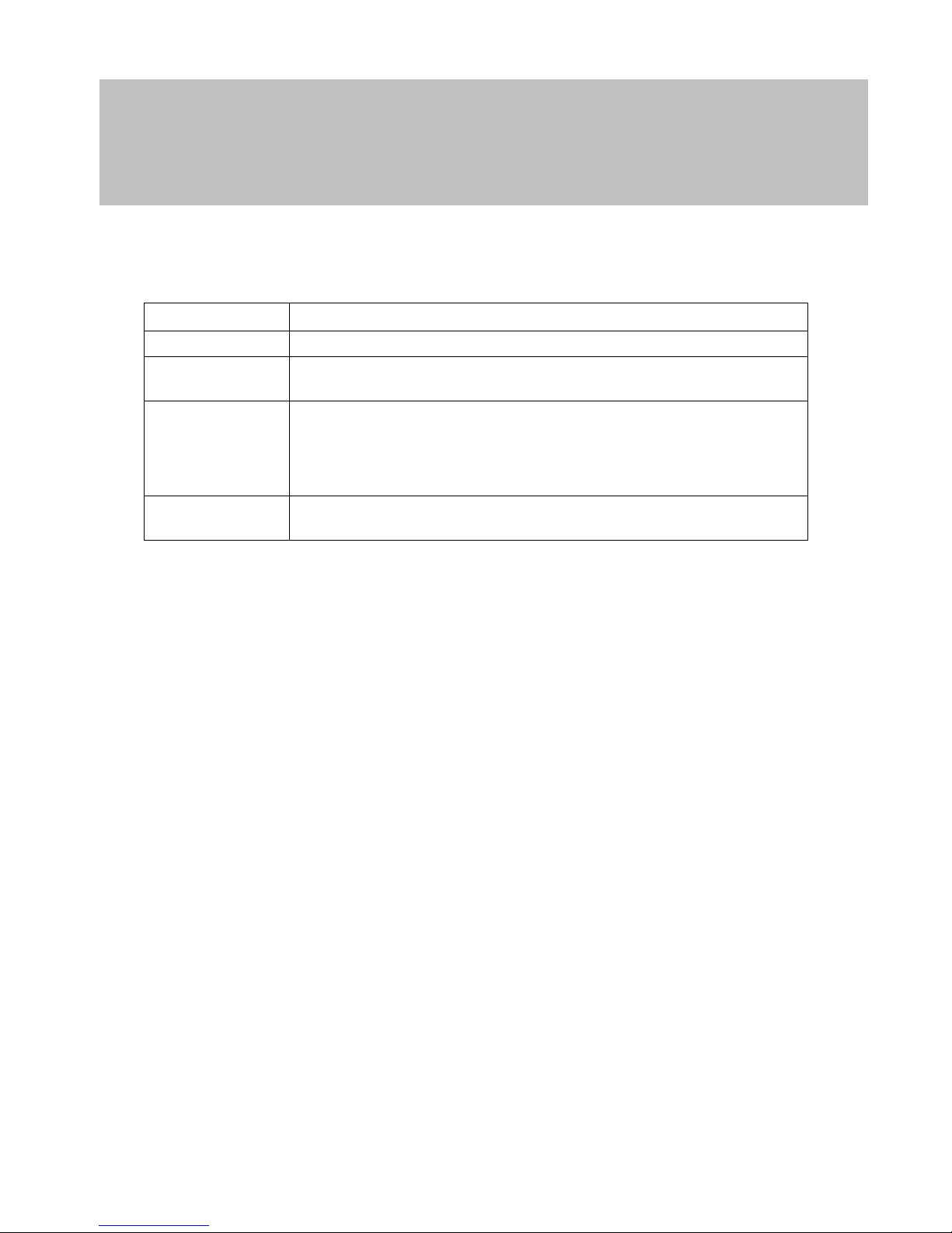
14.0 Technical Specification
Dimensions WxHxD
96 mm x 96 mm x 14 mm
Weight 102 g (incl. batteries)
Material Plastic
Colour Grey with transparent ring
Maximum number of op-
erations with one battery
set
AApprox. 100,000 operations or 10 years
on standby
Operating distance from
locking cylinder
Up to a max. of 40 cm (when the transponder
antenna is parallel to the cylinder antenna)
Operating distance from
SmartRelay
Up to a max. of 120 cm (when the transponder
antenna is parallel to the SmartRelay antenna)
Protection class
IP 65
Working temperature range
-20° C to 50° C (-4° F to 50° F) without moisture
condensation
Battery type
2 x 3 V DC lithium battery type CR2032
Battery replacement
Only by trained personnel
 Loading...