

Page 1

Manual 3060 System
State of: July 2007
SimonsVoss Technologies AG • Feringastraße 4 • 85774 Unterföhring • Germany
Hotline 01805-SV3060 • FAQs www.simons-voss.de
Telefon +49-89-99 228-0 • Fax +49-89-99 228-222
If the contents of the foreign language version of the documentation differ from the contents of the original German version,
the original German version shall apply in case of doubt. We reserve the right to make technical changes.
Page 2

Table of Contents
Version: March 2008
Page 3
Table of Contents
Seite 2
P
PEOPLE TO CONTACT
Sales
Technical
Address in Munich
D
DIGITAL LOCKING SYSTEM 3060
General method of operation
The components
Access control, time zone administration
T
TRANSPONDER 3064
Method of operation
Loss of a transponder
Password-protected transponder
Q
BIOMETRIC TRANSPONDER Q3007
Method of operation
Learn-mode
Recognize-mode
Deleate-mode
BIOMETRIC READER Q3008
Method of operation
Learn-mode
Recognize-mode
Deleate-mode
PINCODE-KEYPAD 3068
Method of operation
Initiation
Programming
Battery warning
V
DIGITAL LOCKING CYLINDER 3061
VDS (TN3)
Method of operation
Installation instructions
Battery warning, battery replacement
Page 4
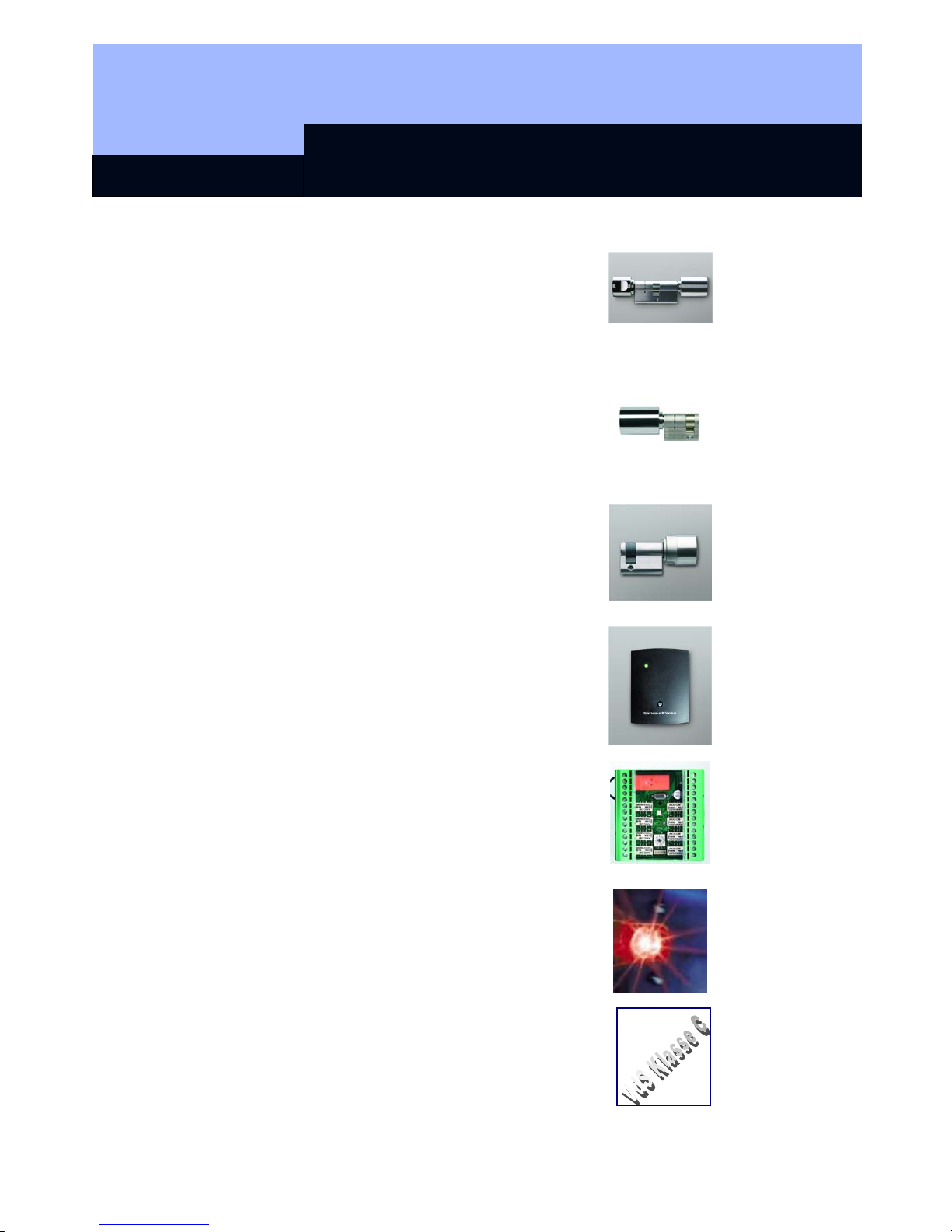
Table of Contents
Seite 3
DIGITAL LOCKING CYLINDER 3061
(TN4)
Method of operation
Installation instructions
Battery warning, battery replacement
H
DIGITAL HALF CYLINDER 3061
(TN3)
Method of operation
Installation instructions
Battery warning, battery replacement
DIGITAL HALF CYLINDER 3061
(TN4)
Method of operation
Installation instructions
Battery warning, battery replacement
R
DIGITAL SMART RELAY 3063
Installation
Connections
Programming
SMART OUTPUT MODULE
Installation
Connections
Programming
SHUNT LOCK FUNCTION 3066
Activation unit
Deactivation unit
Installation and connecting plan
E
SHUNT LOCK FUNCTION 3066 VDS
Master activation unit
Slave activation unit
Deactivation unit
VdS-compliant installation
Page 5
Table of Contents
Seite 4
WAVENET RADIO NETWORK
Components
Structure
Installation
N
LON NETWORK 3065
Network configuration
Components
Installation
M
PROGRAMMING TRANSPONDER 3067
Backup card
Error messages
Programming
P
PALM CD2
Initiation
Export and import
Programming
SMART CD
Initiation
Export and import
Programming +65
K
KEY
Explanation of technical terms
Special Symbols
Page 6

People to contact
Version: September 2006
Page 7

People to contact
Page 2
SALES
If you have any questions please contact our specialist dealers, or the sales
representative responsible for your region. You can obtain information concerning the
responsible contact at the following telephone number.
+49 89-9 92 28-180
United Kingdom
SimonsVoss Technologies Ltd.
Mr. Oliver Quaisser
44 Newton Court, Old Windsor
Berkshire SL4 2SN
Great Britain
Tel. +44 / (0)1753 / 85 98 44
Fax +44 / (0)1753 / 83 17 03
Email: oliver.quaisser@simons-voss.co.uk
Singapore and Asia
SimonsVoss Security Technologies (Asia) Pte. Ltd.
Mr. Jason P. Kurek
72 B Pagoda Street
Republic of Singapore 059231
Tel. (65) 6227 7318
Fax (65) 6227 7018
Email: jpk@simonsvossasia.com
Middle East
SimonsVoss Technologies (Middle East) FZ-LCC
Dubai Internet City
P.O. Box 500188
Dubai, UAE
Tel. +9714 3629761
E-Mail: uae@simons-voss.com
Headquaters Munich
SimonsVoss Technologies AG
Feringastraße 4
85774 Unterföhring
Germany
Tel: +49 89-9 92 28-180
Fax +49 89-9 92 28-222
www.simons-voss.com
Page 8

Digital Locking System 3060
State of: June 2006
Page 9
Digital Locking System 3060
Register
1.0 General Method of Operation ___________________________3
2.0 The Components of the Digital Locking and ________________
Organization System 3060______________________________3
2.1 Software LDB ___________________________________________ 3
2.2 Programming ___________________________________________ 4
2.3 Digital Locking Cylinder 3061 ______________________________ 4
2.4 Digital Smart Relay 3063 __________________________________ 4
2.5 Transponder 3064________________________________________ 4
2.6 Network 3065____________________________________________ 5
2.7 Block Lock Function 3066 _________________________________ 5
3.0 Digital Components With Access Logging and _____________
Time Zone Control ____________________________________5
3.1 Access Logging _________________________________________ 5
3.2 Time Zone Control _______________________________________ 6
Page 10
Digital Locking System 3060
Page 3
1.0 General Method of Operation
The Digital Locking and Organization System 3060 is modularly constructed and is
suitable for uses ranging from a simple locking system for individual doors all the way
to a complex PC-controlled access control system. Conventional mechanical keys are
replaced by the programmable transponder, which controls doors, gates, barriers,
furniture and elevators, for example, over radio transmission. Each transponder is
programmed individually for the locking system. The access authorisations are
assigned by means of the locking plan. This makes it possible to provide each
employee with an individual locking plan with access control and time zone control.
The identification in the system and the radio transmission are done by sending and
receiving constantly changing crypto codes, thus making the misuse of the system
technically practically impossible. Modifications or expansions of the system at a later
date are always possible.
2.0 The Components of the Digital Locking and
Organization System 3060
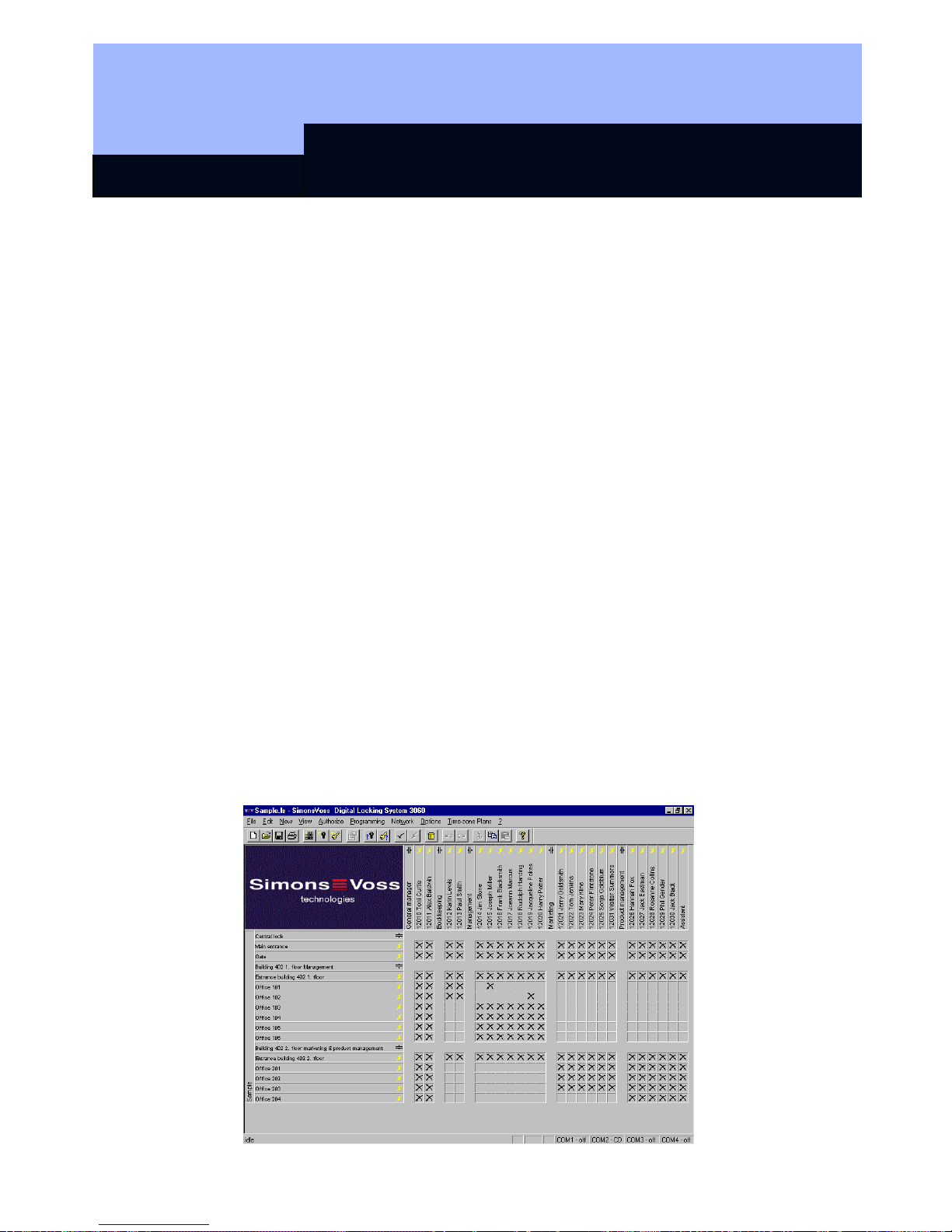
2.1 Software LDB
The locking plan software runs under Windows 98, Windows ME, Windows NT/2000
and Windows XP. All components can be programmed as required using the locking
plan software. One locking plan can contain a maximum of 16,386 lockings and 8000
transponders. For even larger locking systems, the lockings and transponders are
distributed among several locking plans. The locking authorisations are assigned by
simply clicking with the mouse. As a result, later modifications are possible with no
trouble.
☺ A detailed description is to be found in our Software Operating Instructions!
Page 11
Digital Locking System 3060
Page 4
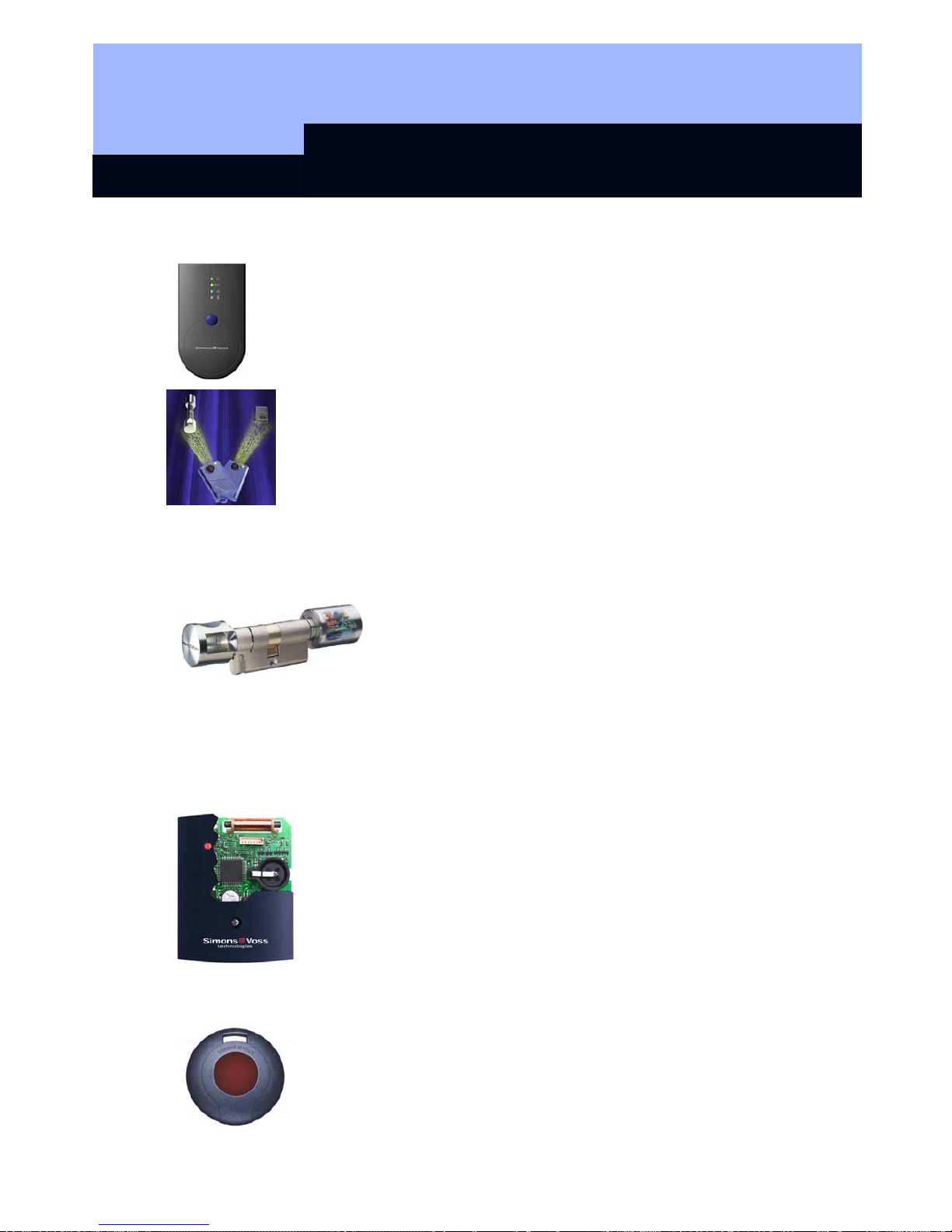
2.2 Programming
You will need the SmartCD and a PDA for programming the digital
components. The data is encoded and then transmitted to the digital
components via radio signal.
Another possibility for programming a Digital Locking Cylinder 3061 and
Transponder 3064 is with the Programming Transponder 3067. For
example, you can issue or change access authorizations in small
systems by simply pressing a button when you lose a key or change the
locking plan. No PC or special system software is needed.
2.3 Digital Locking Cylinder 3061
The Digital Locking Cylinder 3061 is a compact, powerful
access control system that can be installed in any door in
only minutes. Its dimensions correspond to those of an
ordinary mechanical cylinder that meets the norms.
Because the Digital Locking Cylinder 3061 has batteries
(master and backup batteries), it can be installed without
wires in all Euro Profile doors and can replace already
existing
mechanical cylinders. A drop in the battery voltage is indicated by a multilevel
warning system (service life approximately 60,000 operations).
2.4 Digital Smart Relay 3063
The SimonsVoss Smart Relay is an electronic switch that can be
switched with a SimonsVoss transponder. You can use the
SimonsVoss software to configure the authorisation for transponders
that are permitted to operate the Smart Relay. In this way, the Smart
Relay offers the full function of an access control reader.
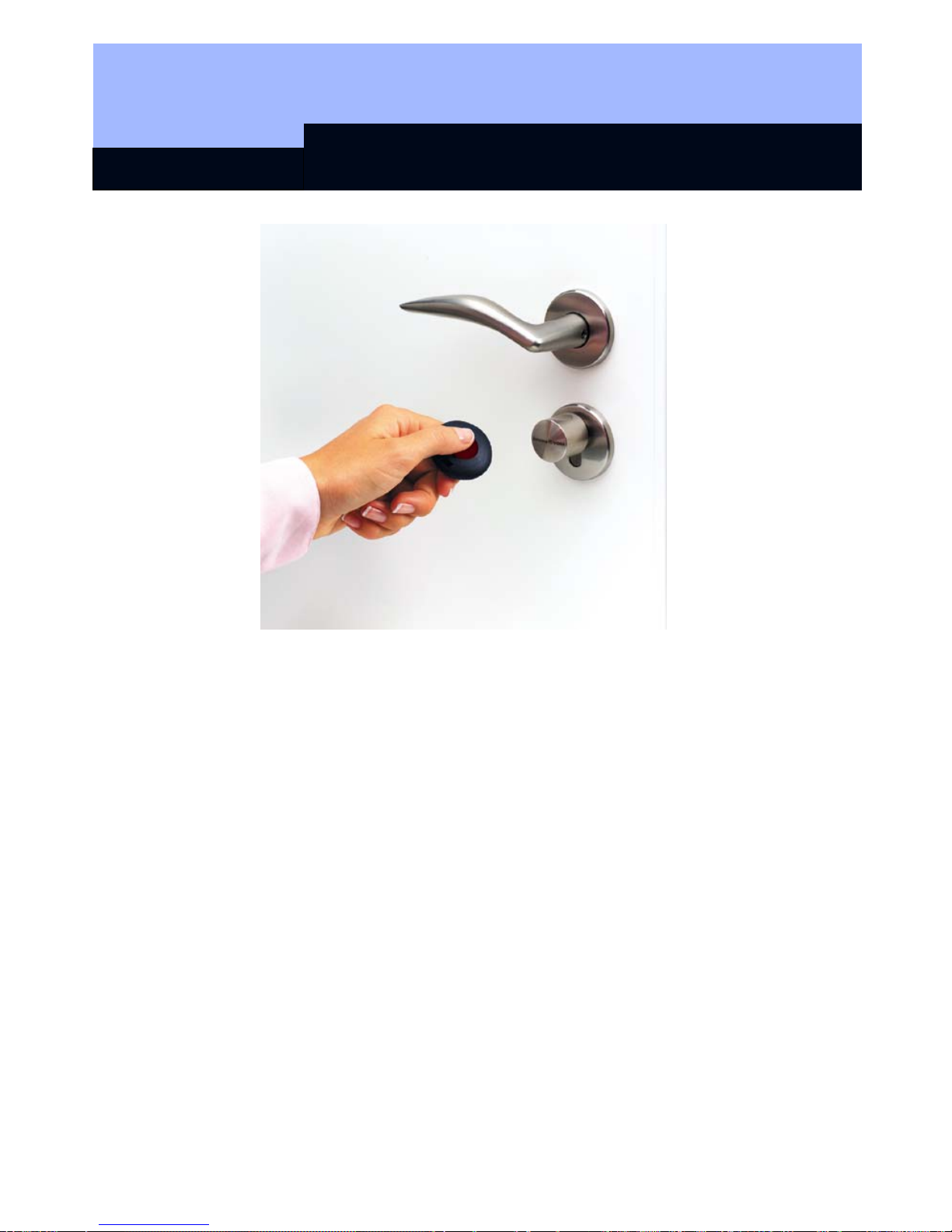
2.5 Transponder 3064
The Transponder 3064 is a digital key that can be programmed
using SimonsVoss software and that works by radio transmission,
without contact. It not only replaces mechanical keys, but also takes
over the function of identity cards. Simply pressing a button triggers
the encoded communication between the transponder and locking
Page 12

Digital Locking System 3060
Page 5
cylinder, Smart Relay or activation unit.
2.6 Network 3065
The cable-free Network 3065 is an online access control system that administers,
visualises and archives all System 3060 information in one central location, and all
without manipulations at the door, door frame or the door hardware.
It is especially recommended for medium-sized and large locking systems in order to
be able to configure and administer the locking system from a central PC. The LON
standard data transmission is done from the PC over the network wiring (twisted pair)
and out to the network nodes (LockNodes), which are installed near a digital
component. From the LockNode, the data is directed without wires over radio
transmission to the digital unit.
☺ While it is true that access to the network software is no longer possible if
there is a power failure (unless the network has been protected by a no-break
power supply), however, all of the locking system’s components that are
equipped with a battery still function.
2.7 Block Lock Function 3066
SimonsVoss has the Block Lock Function 3066 in its product line as an option of the
Digital Locking and Organization System. This function offers the possibility of
activating your alarm system from a central point while at the same time preventing
the monitored doors from being accidentally opened during this time. This rules out
annoying and expensive false alarms right from the start.
The Block Lock Function 3066 is also available as a VdS version
.
3.0 Digital Components With Access Logging and
Time Zone Control
3.1 Access Logging
The Plus versions of the digital locking cylinder, SmartRelay and activation unit record
the access attempts of authorised transponders. The read-out of the access list from
the lockings is done using the SmartCD or, in the case of a networked locking
system, over the LockNodes.
A total till 128 accesses (with Smart Relay 1.024), with date, time of day and
transponder designation can be stored in the access lists of the separate
components. After that, the complete file isn’t deleted, but instead the oldest access is
always overwritten with the new one.
Page 13
Digital Locking System 3060
Page 6
After the access list has been read out with the programming device or network
nodes, it is imported into the PC and administered there by the locking plan software.
A total of 10,000 accesses can be stored in the PC file. When the data is accepted
from the programming device, a comparison is done so that it is always only the
current, new accesses that are accepted into the PC file.
3.2 Time Zone Control
You can program lockings in such a way that authorised transponders are authorised
for access only at certain times.
Transponders normally have no time restrictions, i.e., that are always authorised for
locking 7 days a week, 24 hours a day. However, you can assign transponders to
time groups so that they can open or lock at times that can be freely defined. There
are five different time groups available (for a more precise description, see the
Software Operating Instructions).
Example:
No time restrictions
Mo-Su, 24 hours
Mr. Lewis, Mr. Ludwig, Ms.
Gorges
Group 1 Mo – Fr, 7 am – 5
pm
Mrs. Schulz, Mr. Fichtel
Group 2 Mo – Fr, 9 am – 8 pm
Mrs. Miller, Mr. Karlsen, Mr. Waas
You can draw up an individual time zone plan for each locking.
It is not
possible to equip a standard version with the access logging and time
zone control functions of the TZC-version at some later time.
Page 14

Transponder 3064
State of: September 2006
Page 15

Transponder 3064
Content
1.0 Method of Operation __________________________________3
1.1 General ________________________________________________ 3
1.2 Higher Priority Locking Level ______________________________ 4
2.0 Special Models _______________________________________5
2.1 Password Transponder ___________________________________ 5
2.2 Switching Transponder ___________________________________ 5
2.3 Explosion Protection Transponder__________________________ 5
3.0 Explosion Protection Transponder ______________________6
3.1 General Information ______________________________________ 6
3.2 Standards ______________________________________________ 6
3.3 Grouping _______________________________________________ 6
4.0 Additional Functions __________________________________7
4.1 Time Zone Control _______________________________________ 7
4.2 Validity Date ____________________________________________ 7
4.3 Activation Transponder ___________________________________ 7
5.0 Battery Replacement __________________________________8
5.1 Battery Replacement 3064 _________________________________ 8
5.2 Battery Replacement for the Explosion Protection Transponder _ 8
6.0 Loss of the Transponder _______________________________ 8
6.1 Emergency Opening______________________________________ 8
6.2 Replacement Transponder ________________________________ 8
7.0 Data Sheet___________________________________________ 9
Page 16
Transponder 3064
Page 3
1.0 Method of Operation
1.1 General
The Transponder 3064 is a digital “key” that is programmed with the locking plan
software and that works over radio transmission with no physical contact. All
functions, for example, opening and closing doors, gates, barriers, furniture locks,
etc., are carried out by pressing a button. Communication with the digital components
(cylinder, Smart Relay and activation unit) takes place by sending and receiving
constantly changing crypto codes, which makes misuse practically impossible.
Since the System 3060 works with active transponder technology, the transponder
has its own voltage source (battery) available. The advantage in comparison to
passive technologies lies in the smaller energy requirements of the cylinder and the
larger range.
In order to trigger an action, hold the transponder near the digital locking (refer to the
separate chapters for information on maximum transponder ranges) and then press
the transponder button. Provided that the transponder is authorised for this digital
locking, the desired action, for example, opening or locking the door, can be carried
out.
The housing of the transponder is protected against splash water. However it is not
waterproof!
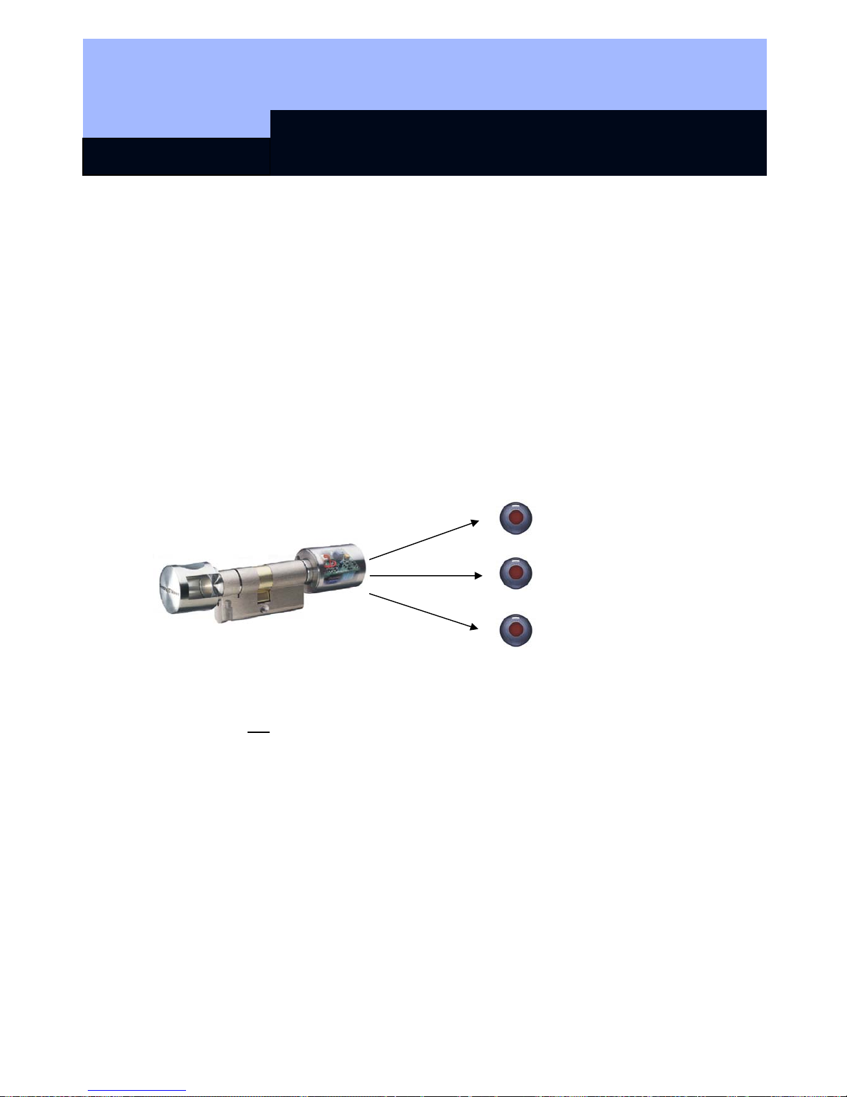
Each transponder can be used in three different, mutually independent locking
systems (assuming that no validity areas were programmed). Each locking system
has its own password and is administered separately.
Example:
Company Branch Private home
900 lockings 85 lockings 3 lockings
Page 17
Transponder 3064
Page 4
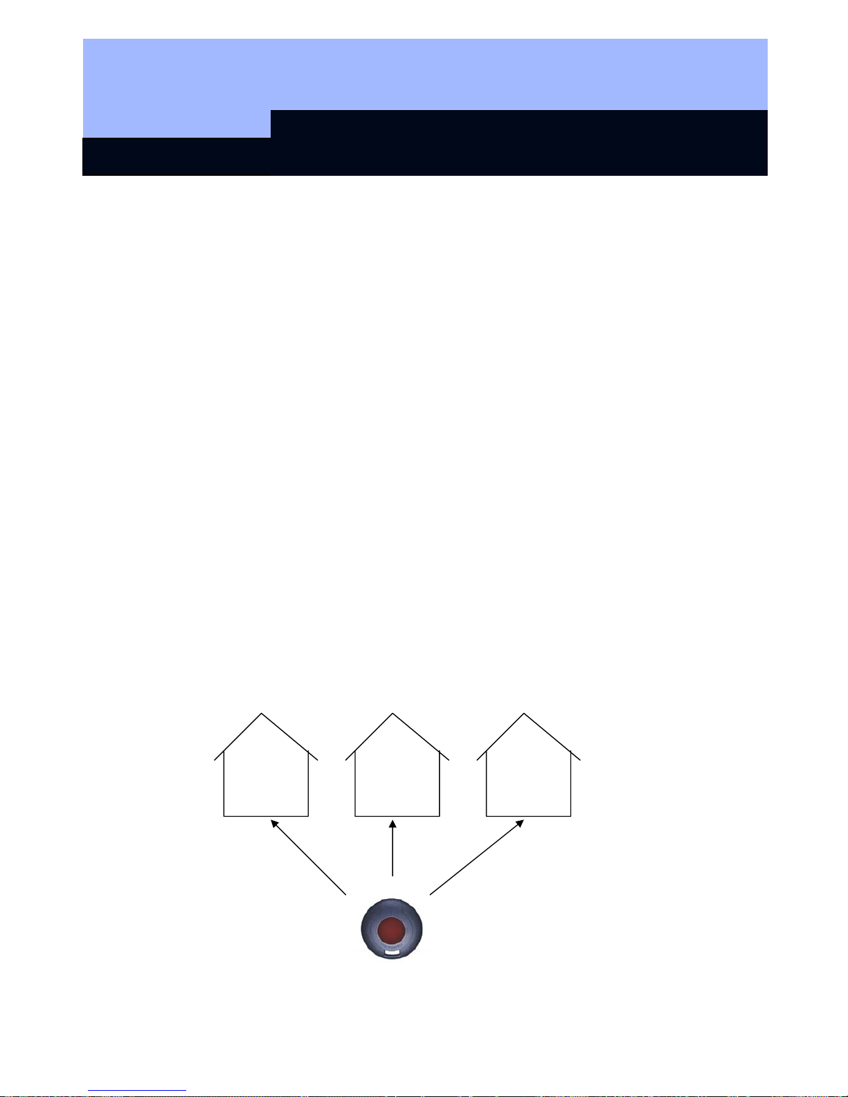
1.2 Higher Priority Locking Level
If it is necessary to have transponders that are authorised for more than 3 mutually
independent locking systems, “higher priority locking levels” must be set up in these
locking systems. There are a maximum of 3 higher priority locking levels available for
this. All transponders of a higher priority locking level have the same authorisation.
One digital locking distinguishes between a maximum of three higher priority levels.
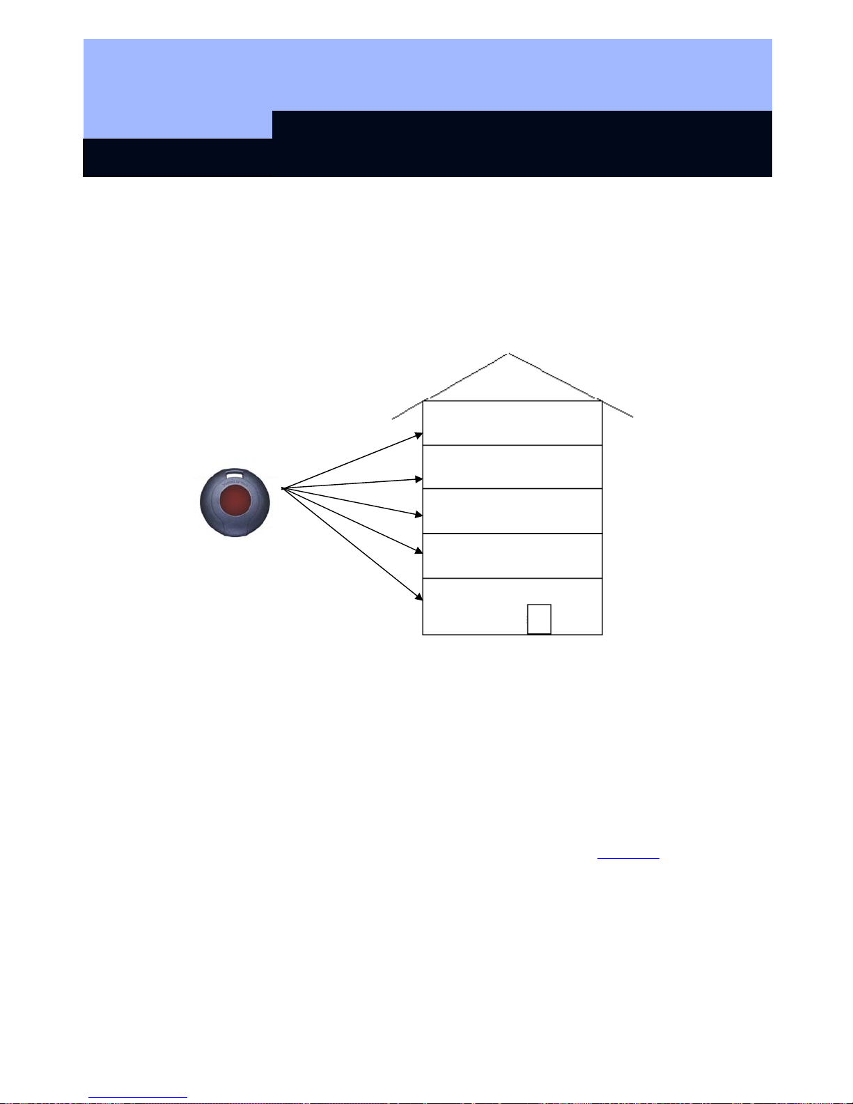
Example:
Higher priority transponder
Four companies are accommodated in an office building with a central locking that is
used by all the companies. Each company administers its own locking system with its
own password. Every employee receives a transponder that is authorised for 2
locking systems, namely the central locking und his or her own company.
However, the fire brigade, for example, needs a transponder that is authorised for all
five of the building’s locking systems. To accomplish this, a higher priority locking
level with the same separate password must be set up in all five locking systems and
the authorisations must be set up for the higher priority transponders. The
transponders set up in this level all have the same authorisation. If higher priority
transponders with other authorisations are required, an additional higher priority
locking level must be set up (max. 3 higher priority locking levels per locking!). The
higher priority transponder must then be programmed into all shutdown
s of all 5
locking systems.
Company D
Company C
Company B
Company A
Central
locking
system
Page 18

Transponder 3064
Page 5
2.0 Special Models
2.1 Password Transponder
Instead of manually entering the locking system password, you can transmit it over
radio frequency with the help of a special transponder. Standard transponders cannot
be used as password transponders.
2.2 Switching Transponder
With this transponder, a two-wire cable (approx. 1m or 37 inches) is connected to the
switch contacts of the button and guided outside the device. When both wires are
connected, the transponder switches through.
Application examples:
• Connecting external systems
• Remote triggering of a Digital Locking Cylinder or Smart Relay
• Block Lock Function 3066: System activation from more than one location
2.3 Explosion Protection Transponder
This is a transponder with the same functions as the Transponder 3064. In addition,
this transponder is released for use in explosion protection zone 1.
(Note Chapter 3 in this regard).
2.4 SmartClip
The special design of this transponder means that the SmartClip is suitable for
holding an ISO 7816 format card.
2.5 Transponder, bonded
The standard transponder as described above, but with a glued-shut casing. This
prevents end-users from opening the case and using the transponder electronics
improperly.
2.6 Transponder, numbered
Sequentially numbered transponders can also be ordered if required.
Page 19

Transponder 3064
Page 6
Explosion Protection Transponder
2.7 General Information
This special product is a transponder that is permitted to be carried into and used in
areas subject to explosion hazards, called Zone 1. An area is denoted as Zone
1 when atmospheres capable of exploding occur occasionally. It is crucial that you
keep in mind the following issues:
• You are not permitted to open the housing.
• Unlike with the Transponder 3064, only SimonsVoss Technologies AG is
permitted to change the battery.
• Normally, you must comply with the general operating instructions of the
BGR132 (German rules for occupational safety and health) when using the
device in Zone 1.
3.2 Standards
The transponder has been tested according to the applicable explosion protection
standards. Refer to:
• Directive 94/9/EC
• DIN EN 50014 (Electrical apparatus for potentially explosive atmospheres)
• DIN EN 50020 (Intrinsic safety "i")
3.3 Grouping
The transponder is grouped in the following way:
• Explosion protection: zone 1
• Intrinsic safety: ib
• Explosion group: IIC
• Temperature class: T3
• Device group: II2 G
This applies to areas in which a potentially explosive atmosphere can arise due to
gases, vapours or mists. The information quoted relates to an ambient temperature of
from -20°C to +40° C (-4° F to +104° F) in the place of use.
Page 20

Transponder 3064
Page 7
3.0 Additional Functions
The following functions can be activated in the locking plan software:
3.1 Time Zone Control
For TZC version digital lockings, you can program transponders that have locking
authorisation for specific times only. These time zones are deposited in the locking
plan software, and the transponders are then assigned to an appropriate time zone
group.
Example: Mr. Miller receives the following authorisation:
Monday to Friday from 9:00 am, until 6:30 p.m.
Saturday from 9:00 am, until 12:45 p.m.
Sunday no authorisation
3.2 Validity Date
It is possible to program transponders whose authorisation is tied to a validity date
(this also applies to non-TZC-versions):
¾ Transponders that are valid from a specific point in time
(e.g., from 8:00 a.m. on July 12, 2003
¾ Transponders that are valid up to a specific point in time
(e.g., until 5:00 p.m. on July 12, 2003
¾ Transponders that are valid for a specific time interval
(e.g., from July 1, 2003 until July 31, 2003)
& One data record is assigned for each activation or expiry date!
3.3 Activation Transponder
Within the scope of the block lock function, all authorised transponders for a digital
locking in the security area are blocked when the alarm system has been activated in
order to avoid false alarms. For emergency situations, transponders can be
programmed (for example, for the fire brigade) that release this block. Afterwards, the
door can be opened with an authorised transponder.
Page 21

Transponder 3064
Page 8
4.0 Battery Replacement
4.1 Battery Replacement 3064
If a battery warning occurs, then the transponder battery can be changed at any time
(see the Manual on the 3061 Locking Cylinder – Battery warning). Open the casing
carefully so that you can see the battery. Open the battery clip and remove the
battery, insert a new one, and close the clip. Press the casing back together again.
When you change the battery it is important to ensure that the procedure does not
take more than two minutes, that the transponder button is not pressed during that
period, and that you do not short the battery – otherwise you may lose data.
Alternatively:
Send the transponder that needs its battery changing to:
SimonsVoss Technologies AG, Eichenweg 6, 07616 Petersberg.
4.2 Battery Replacement for the Explosion Protection Transponder
Attention:
Only SimonsVoss Technologies AG is permitted to change the transponder battery!
5.0 Loss of the Transponder
5.1 Emergency Opening
An emergency opening can be carried out using the SmartCD + PDA (only use
devices approved by SimonsVoss) and with the input of the locking system password.
5.2 Replacement Transponder
If a transponder is lost, it can be deleted from the locking plan and a replacement
transponder can be set up. When operating the locking system in overlay mode, the
lost transponder is automatically blocked as soon as the replacement transponder is
activated at the digital locking. (See the Software Operating Instructions Page H3 for
programming and procedure information.)
Page 22

Transponder 3064
Page 9
6.0 Data Sheet
Housing
• Made of weather-resistant plastic
• Colour: Black
• Degree of protection: IP 65
• Diameter: 42 mm
• Integrated lithium battery
• Max. 1,000,000 operations, or 10 years standby
• Access authorisations for up to 48.149 doors
• Can be used in 3 mutually independent
locking systems
Page 23

Q3007 Biometric Transponder
State of: September 2006
Page 24

Q3007 Biometric Transponder
Content
1.0 General Instructions __________________________________3
1.1 Safety instructions _______________________________________ 3
1.2 Product description ______________________________________ 3
2.0 Overview of function __________________________________ 4
2.1 Basic information on operation_____________________________ 4
2.2 Operating states _________________________________________ 4
2.3 How the transponder works _______________________________ 5
2.4 "Learn" mode: start-up, scanning in fingerprints ______________ 5
2.5 Querying the number of fingerprints scanned in ______________ 8
2.6 "Recognise" mode: one-off triggering of transponder __________ 9
3.0 "Delete" mode: deleting fingerprints ____________________ 10
4.0 Transparent mode ___________________________________ 10
5.0 Programming the Transponder_________________________11
with the SimonsVoss software _________________________11
6.0 Changing the Batteries _______________________________ 11
7.0 Technical Data ______________________________________ 12
8.0 Table of Diode Signals________________________________13
Page 25
Q3007 Biometric Transponder
Page 3
1.0 General Instructions
Please take 15 minutes to familiarise yourself with how your Biometric Transponder
Q3007 works with the help of these operating instructions.
1.1 Safety instructions
Caution! – The batteries used in this product could burn or cause a fire if they are not
handled properly. Do not charge, open or burn these batteries or heat to over 100°C.
Make sure that the sensor surface is not dirty or scratched. Do not drop the Q3007 or
expose it to any other strong impacts.
In addition, please make sure that the initial scanning in of fingerprints is not carried
out by unauthorised persons!
We advise you to protect the Q3007 against unauthorised access if possible.
Handling a Q3007 assumes knowledge of how to use SimonsVoss software.
Programming should therefore only be carried out by trained specialist staff.
SimonsVoss Technologies AG is not liable for any damage caused by incorrect
programming.
An incorrectly programmed or faulty Q3007 can block access via a door. SimonsVoss
AG is not liable for the consequences of such an occurrence, such as blocked access
to persons who are injured or in danger, material damage or any other damage.
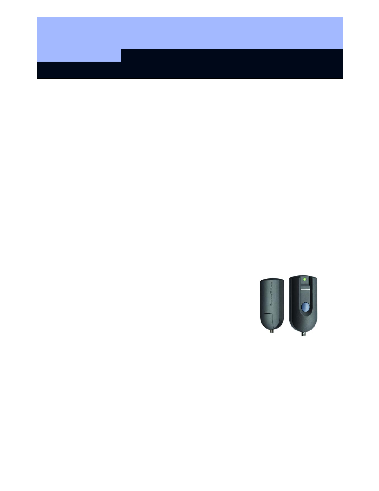
1.2 Product description
The Q3007 differs from normal transponders by the fact that
it is also equipped with a highly sensitive Atmel Fingerprint
Sensor. In just a few seconds, a high-powered processor in
the transponder compares the saved fingerprint with the
fingerprint read in by the sensor. In this way, only people
whose fingerprints have been scanned in already can use
the transponder. This guarantees maximum security against
unauthorised use by third parties, e.g. if the transponder is
unsupervised, or is lost or stolen. The Q3007 is therefore
particularly suitable for applications where a transponder is
provided with very many or very specific authorisations, e.g. if one person has a
general transponder for all doors or access to high-security areas.
Page 26

Q3007 Biometric Transponder
Page 4
2.0 Overview of function
2.1 Basic information on operation
The Biometric Transponder Q3007 scans fingerprints using a fingerprint sensor. The
finger is dragged across the sensor, rather than being pressed against it.
The following should be noted:
The fingerprint to be scanned/ memorised should always be dragged over the sensor
in the same way.
To do this, place the tip of the finger that is to be stored or to be recognised at the
upper edge of the Biometric Transponder and draw it across the sensor from top to
bottom (towards the button) at a constant speed whilst applying slight pressure. The
design of the housing means that the finger is guided properly through the slightly
raised side walls. This more or less excludes the possibility of using the transponder
incorrectly.
The fingerprint sensor can thus pick up the fingerprint line by line and reassemble it
into a complete image in the integrated processor. If the reassembled image matches
the saved image, the Transponder is released.
2.2 Operating states
The Q3007 has four different operating modes:
Mode Function
Standby
The Q3007 is normally on "Standby" in order to save the battery
capacity. After it has completed a function (e.g. scanning), it
always returns to the standby mode.
Learn
In the "Learn" mode, new fingerprints can be memorised. Up to 6
different fingerprints can be saved, two of which are what we call
"administrator" fingerprints. New fingerprints (user fingerprints)
can only be scanned in with the help of an administrator. The
only exception is the scanning of the first two fingerprints
(Administrator fingerprints), see below
Delete
In the "Delete" mode, fingerprints that have been memorised can
be deleted. Individual prints can be deleted, or all fingerprints can
be deleted at once.
Recognise
The "Recognise" mode is the mode before a door is opened. In
this mode, the Transponder is released if a fingerprint is correctly
recognised.
Page 27
Q3007 Biometric Transponder
Page 5
2.3 How the transponder works
You can interrupt the action in each mode by pressing the button briefly to change to
Standby.
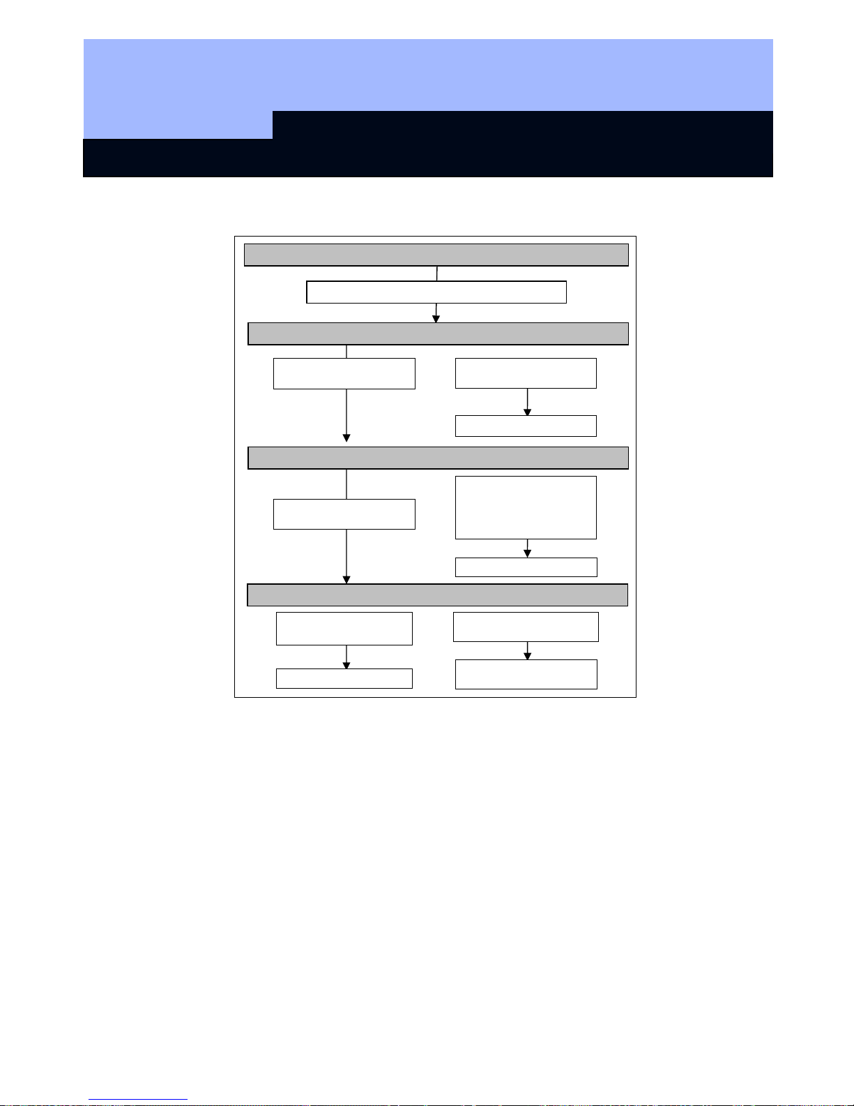
2.4 "Learn" state: start-up, scanning in fingerprints
Initial start-up - scanning in the first 2 fingerprints (Administrator fingerprints)
To start the Q3007, two "Administrator fingerprints" need to be scanned in first of all.
We recommend that a fingerprint from the left and right hand of one person, the
administrator (e.g. safety officer) is used for this. However, you can also use one
finger from two different people.
Stand-by mode: LED not illuminated
Briefly press button once, then release
Recognise mode: LED flashes green
Learn mode: LED flashes yello
w
Delete state: LED flashes red
Drag finger across sensor
Transponder triggered
Press button and hold
down for 3 sec.
New finger is memorised
Press button and hold
down for 3 sec.
Drag Administrator finger
once over sensor and new
finger (User finger) 3 times
over sensor.
Draw user finger once
across sensor
Draw Administrator finger
once across sensor
All fingerprints are deleted
Only user fingerprint is
deleted
Page 28
Q3007 Biometric Transponder
Page 6
Please note:
The first two fingerprints to be scanned in are automatically (!) the Administrator
fingerprints. Without them, no further fingerprints can be scanned in or deleted later!
To scan in and store the first Administrator fingerprint (e.g. left thumb), please do the
following:
1. Briefly press the transponder button; the LED will flash green.
2. Then press the button again and hold it pressed for at least 3 seconds (until the
LED flashes yellow).
3. Release the button. The system is now ready to scan for 30 seconds, and this is
indicated by rapid yellow flashing.
4. As a high quality of the fingerprint to be teached in is important for good
recognition during every day use, please make sure, that your finger to be
scanned in is not too dry (e.g. breath on them before having them scanned
in).
5. Drag finger across the sensor; the LED goes off; after about 1 second, the LED
flashes green once to indicate that the fingerprint has been accepted.
6. When the LED flashes yellow rapidly again, drag the finger to be scanned in
across the sensor again.
7. Now repeat steps 4 and 5 twice again (so that you have drawn your finger three
times across the fingerprint sensor altogether). If an attempt has been
unsuccessful (LED is illuminated red), drag your finger across the sensor again.
Using for the first time – ‘learning’ the first two fingers (Administrator Fingers)
Once the fingerprint has successfully been scanned, the data are saved. This step
takes about 2-5 seconds and is indicated by a yellow light flashing at 2 second
intervals. The diode is then briefly illuminated green, and the Q3007 returns to
Standby.
The Q3007 can now be used by the Administrator, or other fingerprints can be
scanned in. Please note that the second fingerprint that is scanned in also has
Administrator rights!
Scanning in more fingerprints (User fingerprints)
Page 29

Q3007 Biometric Transponder
Page 7
Further fingerprints (maximum 4) can be scanned in as the Administrator fingerprints
have been, except that the Q3007 must first be cleared for this by an Administrator
fingerprint. This prevents unauthorised persons from scanning in their own
fingerprints and thus gaining access rights that are not allowed.
We recommend that every person who is to use the Q3007 should also be scanned in
with two fingerprints, one per hand. This means that three people can be scanned in,
with two fingerprints for each one. To scan in more fingerprints, please proceed as
follows:
1. Briefly press the transponder button and wait until the LED flashes green.
2. Then press the button again and hold it pressed for at least 3 seconds until the
LED flashes yellow, then release the button.
3. Draw the Administrator finger across the sensor; the LED goes off and then
flashes green once after about 2 seconds. The system is now ready to scan for 30
seconds, and this is indicated by rapid yellow flashing light. Drag the User finger
across the sensor; the LED goes off; after about 1 second, the LED flashes green
once to indicate that the fingerprint has been accepted.
4. When the LED flashes yellow rapidly again, draw the finger to be scanned in
across the sensor again.
5. Now repeat step 4 twice again (so that you have drawn your finger three times
across the fingerprint sensor altogether). If an attempt has been unsuccessful
(LED is illuminated red), drag your finger across the sensor again.
Once the fingerprint has successfully been scanned, the data are saved. This step
takes about 2-5 seconds and is indicated by a yellow flashing light at 2 second
intervals. The diode is then briefly illuminated green, and the Q3007 returns to
Standby.
Fingerprints that are already known can always be scanned in, even if 6 fingerprints
have already been saved. Unknown fingerprints are then rejected by the LED flashing
red twice.
Tips:
• Care in scanning in is rewarded by reliable recognition in use.
• Scanning in the same fingerprint several times improves the quality of the
scanned features and thus makes the recognition of the fingerprint more
reliable.
• Use a firm base when scanning in fingerprints. We recommend operation with
one hand when scanning in thumb prints.
• When scanning in fingerprints, drag the finger across the sensor in a straight
line, not too quickly, at an even speed and pressure.
• Make sure that the sensor is clean and that your fingers are not too dry
(e.g. by breathing on them before having them scanned).
Page 30

Q3007 Biometric Transponder
Page 8
6. Now repeat step 4 twice again (so that you have drawn your finger three times
across the fingerprint sensor altogether). If an attempt has been unsuccessful
(LED is illuminated red), drag your finger across the sensor again.
Once the fingerprint has successfully been scanned, the data are saved. This step
takes about 2-5 seconds and is indicated by a yellow flashing light at 2 second
intervals. The diode is then briefly illuminated green, and the Q3007 returns to
Standby.
Fingerprints that are already known can always be scanned in, even if 6 fingerprints
have already been saved. Unknown fingerprints are then rejected by the LED flashing
red twice.
Tips:
• Care in scanning in is rewarded by reliable recognition in use.
• Scanning in the same fingerprint several times improves the quality of the
scanned features and thus makes the recognition of the fingerprint more
reliable.
• Use a firm base when scanning in fingerprints. We recommend operation with
one hand when scanning in thumb prints.
• When scanning in fingerprints, drag the finger across the sensor in a straight
line, not too quickly, at an even speed and pressure.
• Make sure that the sensor is clean and that your fingers are not too dry
(e.g. by breathing on them before having them scanned).
2.5 Querying the number of fingerprints scanned in
You can query the number of fingerprints already scanned in as follows:
1. Press the button once briefly (the LED flashes green)
2. Press the button again and hold it down for 1.5 - 2 seconds (not as long as 3
seconds, which will take you into "learn" mode).
3. The LED flashes red.
4. Then the LED will flash green as many times as the number of fingerprints
scanned in (max. 6).
5. The LED flashes red (for a long time if the maximum possible number of
fingerprints has been reached, or briefly if it has not).
If no fingerprints have been scanned in, the LED flashes red twice and then returns to
Standby mode.
Page 31

Q3007 Biometric Transponder
Page 9
2.6 "Recognise" mode: one-off triggering of transponder
The mode known as the Recognise mode is the normal operating state for the
Q3007, i.e. a person whose fingerprint has been scanned in would like to trigger a
Transponder signal, e.g. to open a door with a digital locking cylinder or to
programme the Transponder within a locking plan.
To do this, proceed as follows:
1. Press the button of the Q3007 briefly (for around 0.5 sec.), and the LED will then
flash green.
2. Now drag your scanned finger over the sensor. Make sure that it is in the same
position as it was when you scanned it in.
3. If the recognition attempt was successful, the LED shows green and the
Transponder is triggered.
If the LED shows red, the recognition attempt was not successful. You can now try
three more times. If these are not successful, the Q3007 automatically returns to
Standby mode.
Please note
:
• It may occasionally happen that the Q3007 does not recognise your finger
even though it has been properly scanned in.
• If the fingerprint is rejected with a single red flash, the quality of the fingerprint
trace was not adequate. This may be due to the fact, for example, that you did
not drag your finger properly across the sensor (too quickly, not straight or not
even) or that the surface of the sensor is dirty. If a finger is too dry, it may
happen that it "judders" across the sensor. If this happens, please repeat the
attempt, or moisten your finger slightly before you do so by breathing on it, for
example. With a little practice, however, you'll soon get the knack.
• If the features of your fingerprint cannot be assigned to any of the scanned
fingerprints, the diode will flash red twice. You may have accidentally
presented a fingerprint that has not been scanned in, or you may have drawn
this finger across the sensor quite differently initially from the way you are
doing it now (e.g. at an angle, or with more or less of your fingertip in contact
with the sensor).
Tip:
Not every fingerprint from a person is recognised equally reliably. If you are often not
recognised with one finger, you should perhaps scan in another finger.
Make sure that the sensor is clean and that your fingers are not too dry dry (e.g.
by breathing on them before having them scanned)..
Page 32

Q3007 Biometric Transponder
Page 10
3.0 "Delete" mode: deleting fingerprints
Both individually scanned fingerprints and all the fingerprints can be deleted from the
memory.
If normal fingerprints (not Administrator fingerprints) are deleted, the other fingers that
have been scanned in are not deleted. No Administrator fingerprint is needed to do
this (any normal user can delete his own fingerprint).
If one of the two Administrator fingerprints is deleted, all the fingerprints are
automatically deleted. The first two fingerprints that are then scanned in are
automatically the Administrator fingerprints again.
Fingerprints are deleted as follows:
1. Briefly press the transponder button and wait until the LED flashes green.
2. Then press the button again and hold it pressed for at least 3 seconds until the
LED flashes yellow. Release the button.
3. Press the button again and hold it pressed for at least 3 seconds until the LED
flashes red. Release the button. You are now in the "Delete" state.
4. Drag finger across sensor.
5. If the first recognition attempt was successful, the LED flashes green. If the
fingerprint is a normal one (user fingerprint), only this fingerprint is deleted; if it
was one of the two Administrator fingerprints, then all the fingerprints are deleted.
Deleting all the fingerprints can take up to 15 seconds. During this time, the diode
flashes red every 2 seconds.
6. If the LED flashes yellow, the recognition attempt was not successful. You can
now try three more times. If these all fail, the Q3007 automatically returns to
Standby mode.
4.0 Transparent mode
It is possible to switch the Biometric Transponder to what is called Transparent mode.
In this state, the biometric inquiry is interrupted for 5 minutes and the Biometric
Transponder can be used as a normal transponder (doors can be opened simply by
pressing a button). At the end of 5 minutes or so, the Biometric Transponder returns
to Standby mode.
Transparent mode is required, for example, for setting/cancelling alarms (if an SV
Shuntlock VdS is installed) or if several doors need to be passed through in a short
time.
Page 33

Q3007 Biometric Transponder
Page 11
To enter Transparent mode, please proceed as follows:
1. Press and hold the transponder button (longer than 1.5 seconds, < 3 sec.). The
LED will flash green rapidly. The Transponder will now react to the button as if it
were in Recognise mode.
2. Drag finger across sensor (LED shows green if the fingerprint is recognised).
3. The Biometric Transponder is triggered and switches to Transparent mode. The
LED flashes red.
4. Pressing the button triggers the system and the LED shows green, followed by
red flashing.
After 5 minutes, the Transponder switches off Transparent mode and returns to
Standby.
Transparent mode can also be switched off manually by pressing the Transponder
button before automatic switch-off until the green LED goes out (approx. 1.5 sec).
5.0 Programming the Transponder with the SimonsVoss software
The "Set validity" function and the "Quasi-proximity mode" are not
available for the
Q3007.
6.0 Changing the Batteries
To replace the batteries, push the battery cover downwards and remove. Take out all
the batteries and replace with new ones. Make sure that the polarity is correct
(stamped into the base of the battery compartment).
Page 34

Q3007 Biometric Transponder
Page 12
7.0 Technical Data
Dimensions: H x W x D
65 x 32 x18 mm
Weight
22 g
Colour
Grey, with blue button
Operating distance,
locking cylinders
approx. 40 cm (if the transponder
(lengthways) is held parallel with the
cylinder antenna)
Operating distance,
Smart Relay
approx. 120 cm (if the transponder is
parallel with the antenna of the Smart
Relay)
Protection category
IP 54
Operating temperature
range
0°C to 40°C without condensation
Battery type
3 V DC lithium battery type CR-1/3N
Page 35

Q3007 Biometric Transponder
Page 13
8.0 Table of Diode Signals
LED Mode
off Standby
off
moving finger on sensor followed by comparison
with scanned fingerprint, please wait (max. 4
seconds)
Slow green flashing light Recognise mode, wait for finger
(max. 30 seconds)
Fast green flashing light Release for transparent mode, wait for finger
(max. 30 seconds)
One green flash Successful action (recognise, learn, save, delete,
trigger)
Slow yellow flashing light Release for Learn mode, wait for Administrator
finger (max. 30 seconds)
Fast yellow flashing light Learn mode, wait for finger (max. 30 seconds)
Yellow flashing light Save scanned finger, please wait (max. 5
seconds)
One or two yellow flashes Error message in Delete state (cf. 1x or 2x red
flashing)
Slow red flashing light Delete state, wait for finger (max. 30 seconds)
Red flashing light Delete scanned fingerprint, please wait (max. 15
seconds)
Red flashing light Transparent state (max. 5 minutes)
Flash red 1x Action unsuccessful
Flash red 2x Fingerprint not recognised
Red, 0 to 6 times green, red Query number of scanned-in fingerprints
Page 36

BIOMETRIC READER Q3008
State of: August 2007
Page 37

MANUAL - BIOMETRIC READER Q3008
Page 2
2
1.0 General information ___________________________________ 4
1.1 Safety information ________________________________________ 4
1.2 Description of product _____________________________________ 5
2.0 Overview of function___________________________________6
2.1 Functional overview _______________________________________ 6
2.2 Basic operation ___________________________________________ 6
2.3 Operating statuses ________________________________________ 8
2.4 Operation ________________________________________________ 8
3.0 Programming_________________________________________9
3.1 Commissioning ___________________________________________ 9
3.2 Programming additional fingerprints (users) _________________ 10
4.0 ‘Recognize’ process __________________________________11
5.0 Assigning fingerprints to transponder IDs ________________12
6.0 Replacing fingerprints ________________________________ 13
7.0 Querying the number of learned fingerprints______________14
8.0 Deleting an individual fingerprint _______________________ 14
9.0 Deleting all fingerprints _______________________________ 15
10.0 Reading the biometric reader __________________________ 15
11.0 Master finger mode __________________________________ 16
11.1 Commissioning – Programming master fingers ______________ 16
11.2 Programming user fingers________________________________ 17
11.3 ‘Recognize’ process _____________________________________ 18
11.4 Deleting individual fingerprints____________________________ 18
11.5 Deleting all fingerprints __________________________________ 18
11.6 Resetting the biometric reader ____________________________ 19
12.0 Manipulation alarm___________________________________19
13.0 Meaning of LED signals_______________________________20
14.0 Battery warning _____________________________________20
15.0 Replacing the battery_________________________________21
Page 38

MANUAL - BIOMETRIC READER Q3008
Page 3
3
16.0 Assembly __________________________________________21
17.0 Special functions ____________________________________22
17.1 Wireless circuit for SimonsVoss VdS shunt lock 3066_________ 22
17.2 Miscellaneous __________________________________________ 22
18.0 Technical data ______________________________________ 23
Page 39

MANUAL - BIOMETRIC READER Q3008
Page 4
4
1.0 General information
Please take 15 minutes to read this manual and
familiarise yourself with the function of your Q3008
biometric reader.
To assemble the housing you will need a Torx key of
size TX6.
1.1 Safety information
Caution! – The battery used in this product may present a risk of fire or burns if
misused. Do not charge or open the battery. Do not heat it to over 100°C or burn it.
Do not short-circuit.
Only use batteries which have been approved by SimonsVoss.
Dispose of old and used batteries in the correct way. Keep out of the reach of
children.
Reversing the polarities may cause damage to the Q3008 biometric reader.
Do not allow the Q3008 biometric reader to become dirty or scratched. Do not drop it
or subject it to any other sudden impact.
It is essential to ensure that the device does not come into direct contact with
moisture and is not exposed to temperatures below +5°C.
The biometric reader is for indoor use only.
Master finger mode should only be used when the device is installed in a secure
indoor location and with a very small number of doors.
Program the reader as soon as it is commissioned to prevent any risk of misuse.
If the reader fails to recognise a finger, or does not recognise it correctly, this does
not necessarily mean there is a defect. SimonsVoss Technologies AG accepts no
liability for poor recognition caused by skin dryness or the physical structure of the
finger.
In order to configure a SimonsVoss biometric reader Q3008 you must be familiar with
the product and SimonsVoss software. The Q3008 biometric reader should therefore
only be programmed by trained specialists.
SimonsVoss Technologies AG shall assume no liability for damage caused by
incorrect programming.
Access through a door may be denied if a Q3008 biometric reader is incorrectly
programmed or is defective. SimonsVoss AG shall assume no liability for
consequences such as denied access to injured persons or persons at risk, damage
to property or any other form of damage.
SimonsVoss Technologies AG reserves the right to make enhancements and
modifications to the product without notice. Consequently, descriptions and
Page 40

MANUAL - BIOMETRIC READER Q3008
Page 5
5
representations in this documentation may vary from the most recent product and
software versions.
Should there be any variations in the content of other language versions of the
documentation, the German original shall apply in the event of any doubt.
This documentation has been produced to the best of our knowledge, but we cannot
guarantee that it is free of errors. We therefore offer no guarantee and accept no legal
responsibility for the consequences of any errors in this manual.
1.2 Description of product
The Q3008 biometric reader is a digital ‘key’ (transponder), designed to be mounted
on a wall, which opens SimonsVoss locks by radio when it recognises an authorised
fingerprint. The difference between this reader and, for instance, a PIN code keypad,
is that it features a highly sensitive Atmel fingerprint strip sensor. A high-performance
processor integrated in the reader compares learned fingerprints with the fingerprints
read by the sensor. If the fingerprint is recognised, the reader addresses the lock,
which can then be opened. This system offers maximum security against
unauthorised use by third parties. This makes the Q3008 biometric reader particularly
suitable for applications where only a few doors need to be accessed by just a few
members of staff, or for additional security for doors or access to high-security areas.
For the system to be configured, the biometric reader must be programmed with the
SimonsVoss programming software and it must learn a finger. Then, when the
authorised finger is recognised, the appropriate lock is released.
The Q3008 biometric reader may only be used in indoor areas (IP41). The product
has its own power supply and can therefore operate self-sufficiently. Assembly is very
simple as there is no need for wiring.
Because of its modular nature, this component can be easily integrated into the
SimonsVoss System 3060 and like all SimonsVoss components can be programmed
with the locking plan software.
Page 41

MANUAL - BIOMETRIC READER Q3008
Page 6
6
2.0 Overview of function
2.1 Functional overview
The Q3008 biometric reader consists of the following components:
• Biometric analysis unit
• Integrated digital transponder which opens the appropriate lock when
triggered by a successful biometric analysis.
The Q3008 biometric reader enables you to address all SimonsVoss locks (e.g.
cylinders, smart relays or even arming units, etc.) using biometry.
The reader can learn up to 50 different fingerprints. Each finger is assigned its own
transponder ID (TID). In SimonsVoss locks (with time control function, i.e. access
control and time zone control) it is also possible to grant an individual time-limited
access to a building and to keep a log of who accessed an area and when they did
so.
2.2 Basic operation
The Q3008 biometric reader scans fingerprints using a strip sensor. The finger is not
placed on the sensor (the small grey rectangle inside the black finger guide) but
drawn across it.
Please note:
The learned finger image must be of good quality in order for the reader to recognise
your fingerprint quickly and easily later on.
So whether you want the reader to learn or recognise your fingerprint, you must
always draw your finger across the sensor in the same way.
Place your finger (the finger to be learned or which has already been learned) in the
finger guide, above the sensor. At a constant speed and with gentle pressure, draw
your finger down the strip sensor from top to bottom as shown in the pictures (moving
towards the LED). Because of the design of the housing, you will find that your finger
is guided clearly by the higher side walls. This makes it very difficult to operate the
reader wrongly.
The strip sensor reads the fingerprint line by line and reassembles these lines in the
integrated processor to form a complete image. If the assembled image corresponds
to a stored image, the transponder is triggered.
Page 42

MANUAL - BIOMETRIC READER Q3008
Page 7
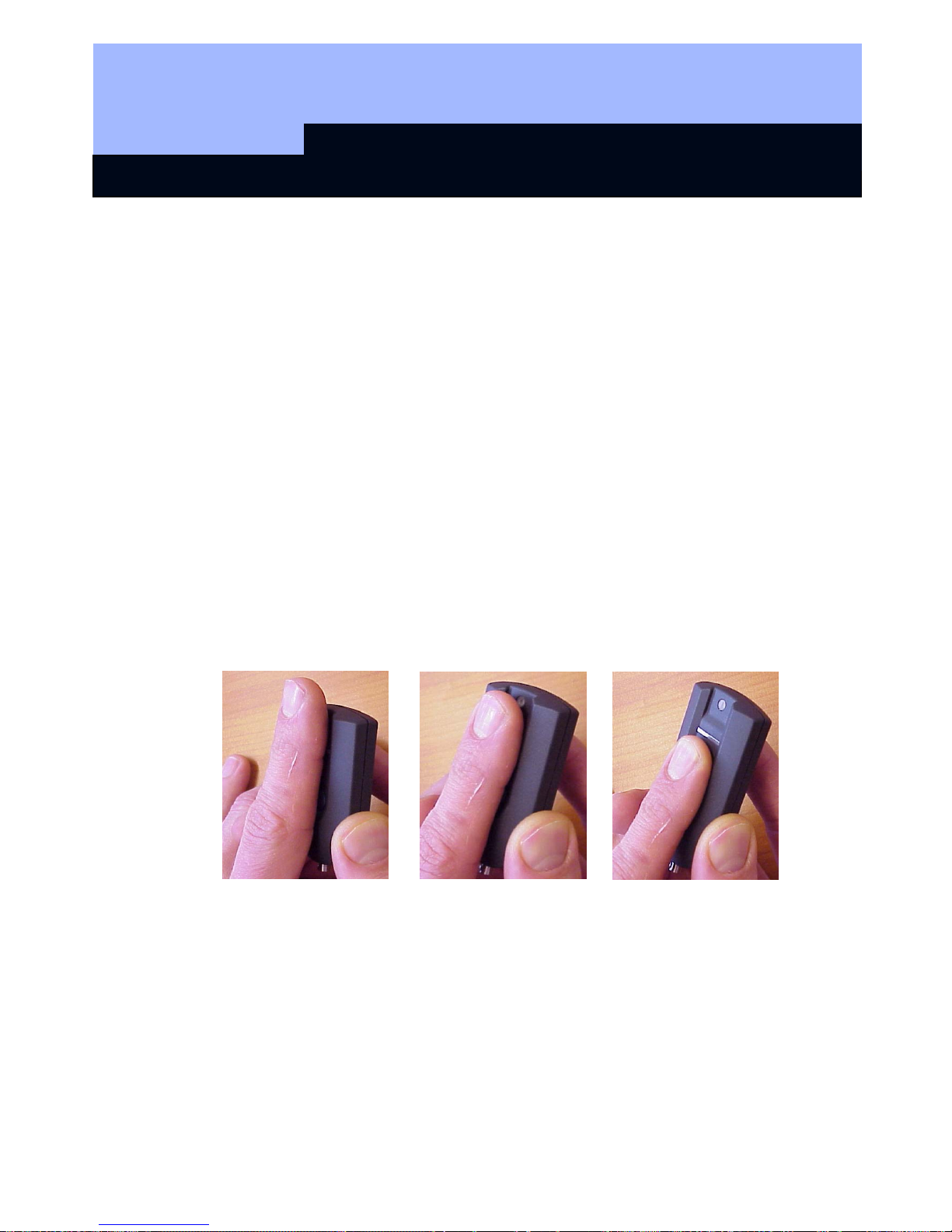
7
Activate the biometric reader by placing your
finger on the finger guide (see chapter 2.4),
and then place your finger at the top of the
sensor.
Figure 1
Draw your finger across the sensor at an even
speed and applying gentle pressure.
Figure 2
Keep your finger straight and extended, i.e. do
not bend or curl it.
Figure 3
When scanning your finger please ensure that your finger remains in contact with the
sensor at all times. In other words, you should maintain gentle pressure on the sensor
during the scanning process.
Page 43

MANUAL - BIOMETRIC READER Q3008
Page 8
8
2.3 Operating statuses
The Q3008 biometric reader distinguishes between 5 different operating statuses:
Status:
Explanation:
Standby The biometric reader is in idle mode and consumes very little power.
Recognize Recognize mode is the status used before an attempt is made to open
a door.
Once an authorised fingerprint is recognised, the lock is
addressed by radio and can then be opened.
Learn
In this mode, the relevant integrated transponders (up to 50) can be
programmed or reset with the SimonsVoss software.
The reader can store up to 50 different fingerprints.
Delete In delete mode, learned fingerprints can be deleted. You can delete
individual fingerprints or all fingerprints.
Battery warning A battery warning system gives you adequate warning when a battery
needs replacing.
2.4 Operation
Once the Q3008 biometric reader has been commissioned and configured, it forms a
‘wireless circuit’ with a SimonsVoss lock within the System 3060. The following
chapters describe in detail how to program individual fingerprints and the relevant
transponder data records and how to use the Q3008 biometric reader.
Finger guide
Sensor
LED
Page 44

MANUAL - BIOMETRIC READER Q3008
Page 9
9
3.0 Programming
The following chapters describe the programming process in detail. If you are using
the biometric reader in a small-scale locking system, please refer to chapter 11.0
Master finger mode.
Do not undertake any programming after a battery warning. Replace the battery
before proceeding. Refer to chapter 15.0 Replacing the battery.
3.1 Commissioning
Please note:
The 3008 biometric reader must be created in the locking plan as a lock
(biometric reader) and users as transponder type biometric reader users. Users
(transponder IDs) and fingerprints can only be learned in situ with the SmartLSM and
the SmartCD.
Please proceed as follows:
1. Create a locking plan in the SimonsVoss software.
2. Create ‘biometric reader’ as a lock
Æ
biometric reader.
3. Create lock (e.g. locking cylinder).
4. Create transponder using the option Biometric reader user.
5. Issue authorisation for the ‘biometric reader’ and the corresponding lock.
6. Connect the SmartCD to the PC and bring within communication range of the
‘biometric reader’.
7. Highlight the biometric reader and launch ‘Programming Æ Lock’ in the
programming software. This is where you undertake basic configuration of the
biometric reader.
8. Once the reader has been successfully programmed, this is indicated by a pop-
up window. This time, the yellow programming lightning symbol remains
displayed in the locking plan.
9. Bring the SmartCD into the communication range of the lock to be addressed.
10. Highlight the lock to be addressed by the biometric reader and launch
‘Programming Æ Lock‘ in the programming software. This is where you
undertake basic configuration of the lock.
11. Once the lock has been successfully programmed, this is indicated by a pop-up
window.
The following programming steps are performed in situ with a PDA and
SmartLSM:
12. Export the complete locking plan (pocket PC).
13. Bring the SmartCD into the communication range of the biometric reader.
Page 45

MANUAL - BIOMETRIC READER Q3008
Page 10
10
14. In SmartLSM, launch the ‘Read’ locks function. The biometric reader is
recognised and read.
15. Select ‘Modify transponder‘ and start the function by selecting ‘Execute’.
16. Select the appropriate transponder (biometric reader user) and launch the
‘Programming’ function.
17. While the transponder is being programmed, the biometric reader automatically
switches to Learn mode (LED flashes yellow), and you will be asked to draw
your finger over the finger guide.
18. Draw the finger you want the reader to learn over the sensor.
19. If the fingerprint is recognised, the LED on the biometric reader gives two long
flashes in green.
20. If programming was successful, the message “Programming successful“
appears in the SmartLSM. The fingerprint has been successfully stored.
21. After you re-import the locking plan the programming lightning symbols
disappear, both from the transponder and the biometric reader (if all
transponders have been programmed).
3.2 Programming additional fingerprints (users)
To learn additional users, proceed as follows:
1. Create transponder using the option Biometric reader user.
2. Issue authorisation for the ‘biometric reader’ and the corresponding lock (e.g.
locking cylinder).
3. Fully export the locking plan (pocket PC).
4. Bring the SmartCD into the communication range of the biometric reader in situ.
5. In SmartLSM, launch the ‘Read’ locks function.
6. Select ‘Modify transponder‘ and start the function by selecting ‘Execute’.
7. Select the appropriate transponder (biometric reader user) and launch the
‘Programming’ function.
8. While the transponder is being programmed, the biometric reader automatically
switches to Learn mode (LED flashes yellow), and you will be asked to draw
your finger over the finger guide.
9. Draw your finger over the sensor.
10. If the fingerprint is recognised, the LED on the biometric reader gives two long
flashes in green.
11. If programming was successful, the message “Programming successful“
appears in the SmartLSM. The fingerprint has been successfully stored in the
biometric reader.
Page 46

MANUAL - BIOMETRIC READER Q3008
Page 11
11
12. If you want the reader to learn other fingerprints, repeat from step 4. You must
first create additional transponders in the software using the biometric reader
user option (see step 1) and assign authorisations to them.
13. Bring the SmartCD into the communication range of the lock to be addressed in
situ.
14. In SmartLSM, launch the ‘Execute’ function.
15. If programming was successful, the message “Programming successful“
appears in the SmartLSM. The new biometric reader users have been
successfully stored in the lock.
16. After you import the locking plan the programming lightning symbols disappear,
both from the biometric reader user and the biometric reader (if all transponders
(biometric reader users) and the corresponding lock have been programmed).
4.0 ‘Recognize’ process
‘Recognize’ mode is the normal operation for the Q3008 biometric reader, where a
person whose fingerprint has been learned wants to open a door using a digital
locking cylinder.
Please proceed as follows:
1. When the finger is placed on the finger guide, an integrated proximity sensor
activates the biometric reader. After about 0.5 seconds, the LED flashes green.
2. You can now draw your finger (the one learned by the reader) across the sensor,
with gentle pressure, making sure that the whole of the top finger joint passes
over the sensor (refer to photos in chapter 2.2). Make sure that your finger is in
roughly the same position as when the fingerprint was learned.
3. If the fingerprint is recognised and the integrated transponder has been
successfully programmed, the LED flashes green twice and the biometric reader
is triggered.
If the LED lights up red, fingerprint recognition was not successful. If this happens,
you must start again from step 1.
If you moved your finger too quickly over the sensor, the LED gives one rapid flash in
red and then turns green again. Draw your finger across the sensor again, this time
slightly slower.
If the fingerprint is recognised, the LED will light up green. However, if the lock could
not be contacted the LED will light up red again. If this happens, start again from step
1.
Please note
:
• The Q3008 may occasionally fail to recognise a fingerprint even though it was
correctly learned.
Page 47

MANUAL - BIOMETRIC READER Q3008
Page 12
12
• If a fingerprint is rejected and the LED lights up red, the quality of the scan was
not sufficient. This may be because the finger was not moved correctly across
the sensor (not straight or not evenly, for example), or because the surface of the
sensor is dirty. If the finger is too dry, it may ‘judder’ across the sensor. Please try
again. You may wish to dampen your finger slightly first, for example by breathing
on it.
• If the features of your finger could not be assigned to any learned fingerprint, the
diode will light up red. You may have inadvertently used the wrong finger.
Alternatively, you may have moved your finger differently over the sensor when
the reader was learning your fingerprint (for example by turning the finger or with
more or less fingertip).
Tip:
A person’s fingerprint will not be recognised first time, every time. If you find that a
fingerprint is frequently not being recognised, please have the reader learn a different
finger.
Dry fingers can make fingerprint recognition more difficult. This can be
remedied by moistening your finger or breathing on it, for example.
5.0 Assigning fingerprints to transponder IDs
The maximum of 50 different fingerprints are assigned 50 different transponder IDs.
In order to use and differentiate between these 50 different fingerprints, they must be
individually programmed.
Each fingerprint is assigned a unique transponder ID (TID). If the locks in a system
feature a time control function (i.e. access control), the TIDs are stored in the locks
whenever access takes place. This allows you to track which user was given access
when.
It is therefore essential to ensure that you keep the same allocations during
programming. Otherwise access to the lock may not be guaranteed.
Page 48

MANUAL - BIOMETRIC READER Q3008
Page 13
13
6.0 Replacing fingerprints
You can replace existing fingerprints with new ones at any point, for example if an
employee has left the company or no longer requires access through a certain door.
Do not undertake any programming after a battery warning. Replace the battery
before proceeding. Refer to chapter 15.0 Replacing the battery.
Please proceed as follows:
1. Open the locking plan with the SimonsVoss software.
2. Export the locking plan (pocket PC).
3. Bring the SmartCD into the communication range of the biometric reader.
4. In SmartLSM, launch the ‘Read’ locks function.
5. Select ‘Modify transponder‘ and start the function by selecting ‘Execute’.
6. Select the appropriate transponder (biometric reader user) and launch the
‘Programming’ function.
7. While the transponder is being programmed, the biometric reader automatically
switches to Learn mode (LED flashes yellow), and you will be asked to draw
your finger over the finger guide.
8. Draw the new finger over the sensor.
9. If the fingerprint is recognised, the LED gives two long flashes in green.
10. If programming was successful, the message “Programming successful“
appears in the SmartLSM. The fingerprint has been successfully stored.
11. After you import the locking plan the programming lightning symbols disappear,
both from the programmed transponder (biometric reader user) and the
biometric reader (if all transponders (biometric reader users) have been
programmed).
To replace additional fingerprints, repeat from step 3.
Page 49

MANUAL - BIOMETRIC READER Q3008
Page 14
14
7.0 Querying the number of learned fingerprints
You can query the number of learned fingerprints / transponder IDs at any time.
Please proceed as follows:
1. Open the locking plan with the SimonsVoss software.
2. Export the locking plan (pocket PC).
3. Bring the SmartCD into the communication range of the biometric reader.
4. Select the ‘Read‘ function.
5. Select the ‘Modify trans.‘ function.
6. Select the ‘Execute‘ function.
7. You will see a list of all users. Approved biometric reader users are indicated by
a thick black cross.
8.0 Deleting an individual fingerprint
Do not undertake any programming after a battery warning. Replace the battery
before proceeding. Refer to chapter 15.0 Replacing the battery.
To delete an individual fingerprint, proceed as follows:
1. Open the locking plan with the SimonsVoss software.
2. Remove the cross indicating authorisation from the locking plan by clicking on it.
3. Export the locking plan (pocket PC).
4. Bring the SmartCD into the communication range of the biometric reader.
5. Select the ‘Read‘ function.
6. Select the ‘Modify trans.‘ task.
7. Select the ‘Execute‘ function.
8. Select the relevant transponder.
9. Select the ‘Program.‘ function.
10. Following successful programming, the SmartLSM will display the message
“Programming successful“ and a green dot.
11. Re-import the locking plan.
The fingerprint and transponder ID have now been deleted from the biometric reader.
Page 50

MANUAL - BIOMETRIC READER Q3008
Page 15
15
9.0 Deleting all fingerprints
Do not undertake any programming after a battery warning. Replace the battery
before proceeding. Refer to chapter 15.0 Replacing the battery.
To delete all stored fingerprints from the Q3008 biometric reader at the same time,
you need to completely reset the device. Please proceed as follows:
1. Open the locking plan with the SimonsVoss software.
2. Export the locking plan (pocket PC).
3. Bring the SmartCD into the communication range of the biometric reader.
4. Click on the ‘Select‘ function.
5. Select ‘Biometric reader’.
6. Select the ‘Read‘ function.
7. Select ‘Reset‘ and confirm by selecting ‘Execute’.
8. Enter the password for the locking system or take ‘From the database’ and click
on ‘Start’.
9. Re-import the locking plan.
10.0 Reading the biometric reader
It is possible at any time to read the biometric reader and identify programmed
transponders using the SimonsVoss locking plan software.
Please proceed as follows:
1. Open the locking plan with the SimonsVoss software.
2. Export the locking plan (pocket PC).
3. Bring the SmartCD into the communication range of the biometric reader.
4. Click on the ‘Select‘ box.
5. Select the biometric reader.
6. Start the ‘Read lock’ function in the SimonsVoss SmartLSM.
Page 51

MANUAL - BIOMETRIC READER Q3008
Page 16
16
11.0 Master finger mode
Master finger mode was developed specially for small locking systems. The biometric
reader is programmed once and fingerprints can then be learned simply on the
biometric reader itself. No distinctions can be made using different transponder IDs
(TIDs), because no TIDs are learned in master finger mode.
Generally, we recommend using SimonsVoss programming software for
programming purposes.
You can exit master finger mode at any time. To do this, all learned fingerprints
(including the master fingers) must be deleted.
Do not undertake any programming after a battery warning. Replace the battery
before proceeding. Refer to chapter 15.0 Replacing the batteryFehler! Es wurde
kein Textmarkenname vergeben.Fehler! Es wurde kein Textmarkenname
vergeben..
11.1 Commissioning – Programming master fingers
The following chapters describe in detail the programming process for master finger
mode.
Please note:
The first two fingerprints learned are automatically stored as the master
fingers. A master finger cannot also be programmed as a user finger (it will be
rejected during the learning process, indicated by 4 red flashes). Unlike normal mode,
individual fingerprints cannot be allocated a transponder ID (TID), i.e. the lock does
not make a distinction between individual users. In master finger mode it is possible
to use the biometric reader to produce an access log for all locks in the same system.
Please proceed as follows:
1. Create a locking plan in the SimonsVoss software.
2. Create ‘biometric reader’ as a lock
Æ
biometric reader.
3. Create lock (e.g. locking cylinder).
4. Connect the SmartCD to the PC and bring within communication range of the
‘biometric reader’.
5. Highlight the biometric reader and launch ‘Programming Æ Lock’ in the
programming software. This is where you undertake basic configuration of the
biometric reader.
6. If programming was successful, the programming lightning symbol disappears
from the locking plan for the relevant biometric reader.
7. Bring the SmartCD into the communication range of the lock.
Page 52

MANUAL - BIOMETRIC READER Q3008
Page 17
17
8. Highlight the lock to be addressed by the biometric reader and launch
‘Programming Æ Lock‘ in the programming software. This is where you
undertake basic configuration of the lock.
Please perform the next steps on the biometric reader itself. The first two
fingerprints are automatically stored as the master fingers!
9. Place your finger on the sensor to activate the biometric reader.
10. The biometric reader automatically switches to Learn mode (LED flashes slowly
in yellow).
11. Draw the finger to be learned as the master finger across the sensor, for as long
as the LED keeps flashing slowly in yellow. (If the LED starts flashing quickly in
yellow (indicating time-out), wait until the LED goes out and start again.)
12. If the fingerprint is recognised, the LED gives one long flash in green (fingerprint
recognised). The LED gives one more long flash in green. The first master
finger has now been stored.
13. To learn the second master finger (which must be different from the first one),
please repeat from step 7.
Only once both master fingers have been successfully stored can the reader start
learning user fingers. The persons chosen as the master fingers should be the locking
system administrator or other persons with direct access to the locking system. As a
general principle, ensure that only one finger of each hand is used to program in the
master fingers.
11.2 Programming user fingers
Please perform the next steps on the biometric reader itself. The first two fingerprints
learned are automatically stored as the master fingers!
1. Place your finger on the sensor to activate the biometric reader. The LED
flashes slowly in green.
2. Draw a master finger across the sensor.
3. The biometric reader automatically switches to Learn mode (LED flashes slowly
in yellow).
4. Draw the finger to be learned across the sensor, for as long as the LED keeps
flashing slowly in yellow. (If the LED starts flashing quickly in yellow (indicating
time-out), wait until the LED goes out and start again.)
5.
If the fingerprint is recognised, the LED gives one long flash in green (fingerprint
recognised). The LED gives one more long flash in green. The user finger has
now been stored.
6. To program additional user fingers, repeat from step 1.
Page 53

MANUAL - BIOMETRIC READER Q3008
Page 18
18
11.3 ‘Recognize’ process
Please refer to chapter 4.0 Recognize process.
11.4 Deleting individual fingerprints
To delete an individual fingerprint, proceed as follows:
1. Place your finger on the sensor to activate the biometric reader. The LED
flashes slowly in green.
2. Draw a master finger across the sensor.
3. The biometric reader automatically switches to Learn mode (LED flashes slowly
in yellow).
4. Wait until the LED flashes quickly in yellow.
5. Touch the finger guide briefly three times with your finger.
6. The biometric reader automatically switches to Delete mode (LED flashes
slowly in red).
7. Draw the user finger over the sensor.
8. The LED gives two slow flashes in green. The user finger has been deleted.
11.5 Deleting all fingerprints
To delete all stored fingerprints from the Q3008 biometric reader, you need to delete
the complete fingerprint database. Please proceed as follows:
1. Place your finger on the sensor to activate the biometric reader. The LED
flashes slowly in green.
2. Draw a master finger across the sensor.
3. The biometric reader automatically switches to Learn mode (LED flashes slowly
in yellow).
4. Wait until the LED flashes quickly in yellow.
5. Touch the finger guide briefly three times with your finger.
6. The biometric reader automatically switches to Delete mode (LED flashes
slowly in red).
7. Draw a master finger over the sensor.
8. The LED gives two slow flashes in green. All learned fingers (including both
master fingers) are deleted.
The biometric reader retains all locking system data. It can now learn new master and
user fingers. Once this is done the biometric reader will be available again in the
locking system.
Page 54

MANUAL - BIOMETRIC READER Q3008
Page 19
19
11.6 Resetting the biometric reader
To delete all stored fingerprints from the Q3008 biometric reader at the same time
(including the locking system data), or if you want to exit master finger mode, you
need to delete the complete fingerprint database and reset all locking system data.
Please proceed as follows:
1. Open the locking plan with the locking plan software.
2. Select the appropriate biometric reader.
3. Connect the SmartCD to the PC and bring within communication range of the
‘biometric reader’.
4. Highlight the biometric reader and launch ‘Programming Æ Reset lock’ in the
programming software.
5. Once the lock has been successfully programmed, this is indicated by a pop-up
window.
The biometric reader is now back in its original state and can be used for a different
locking system.
12.0 Manipulation alarm
After 15 failed attempts, i.e. attempts to operate the biometric reader with a nonprogrammed fingerprint, the biometric reader reports a manipulation attempt. After
each failed recognition, the LED will then flash red for 60 seconds. No fingers will be
accepted during this time. Following correct recognition of a fingerprint, the
manipulation counter is reset to zero.
Page 55

MANUAL - BIOMETRIC READER Q3008
Page 20
20
13.0 Meaning of LED signals
The LED can light up in three colours: green, yellow and red. These colours have the
following meanings:
• Green Reader activated, awaiting fingerprint
Fingerprint recognised, signal to open sent
Fingerprint learning process successful
• Yellow Battery warning
Learn mode
• Red Fingerprint not recognised
Delete mode
Fingerprint not recognised during learning process
Attempt to program master finger as user finger
Maximum number of learnable fingers reached
Lock not reached
14.0 Battery warning
The Q3008 biometric reader features a battery warning system to provide information
about the status of the device and to minimise operating errors.
The system gives adequate warning of decreasing battery capacity. This alerts you to
the need to change the battery in plenty of time.
Battery warning:
A time delay is added to the ‘recognise’ process. The diode flashes
YELLOW for 10 seconds
. Once the 10 seconds have elapsed, the Q3008 biometric
reader issues the command to open.
Page 56

MANUAL - BIOMETRIC READER Q3008
Page 21
21
15.0 Replacing the battery
Generally speaking, the battery should only be replaced by a trained specialist. To
open the housing you will need a Torx key of size TX6. Please proceed as follows:
1. Fully unscrew the two screws from the base of the housing.
2. Remove the front of the housing.
3. Remove the battery from the holder.
4. Insert the new battery, making sure that the positive terminal is to the right; refer
to markings on circuit board. (Please note: polarity MUST be correct!).
5. Reassemble the housing.
6. Screw the two screws back into the base of the housing.
After the battery has been changed, all functions will be available again.
When replacing the battery it is essential to ensure that no water can penetrate into
the housing and no electronic parts come into contact with water.
When replacing the battery, and immediately after inserting the battery, be careful not
to touch the sensor or finger guide. This could lead to a loss of locking system data.
16.0 Assembly
Generally speaking, assembly should only be performed by a trained specialist. To
mount the biometric reader on a wall, near the lock it is intended to open, you can use
the screws (including dowels) supplied. To open the housing you will need a Torx key
of size TX6. Please proceed as follows:
1. Fully unscrew the two screws from the base of the housing.
2. Remove the front of the housing. Be very careful not to drop the transponder or
subject it to any other sudden impact.
3. Drill the appropriate holes in the wall, using the rear panel of the biometric reader
as a drilling template if required.
4. Attach the rear panel to the wall using the screws.
5. Reassemble the housing.
6. Screw the two screws back into the base of the housing.
When assembling the unit it is essential to ensure that the sealing ring fits properly,
that no water can penetrate into the housing and no electronic parts come into
contact with water.
Page 57

MANUAL - BIOMETRIC READER Q3008
Page 22
22
17.0 Special functions
17.1 Wireless circuit for SimonsVoss VdS shunt lock 3066
The biometric reader can be used to activate SimonsVoss arming units (VdS shunt
lock 3066). The reader is fitted within the transmission range of the VDS arming unit
for this purpose. When the correct fingerprint is recognised, the arming unit is
addressed and the alarm system is armed or disarmed via the shunt lock.
For arming/disarming processes, VdS-certified arming units from SimonsVoss require
a double opening protocol (double-click if to be armed/disarmed by transponder).
An external software tool from SimonsVoss allows the biometric reader to be
reconfigured to shunt lock mode. The configuration emulates the required ‘doubleclick’ and the biometric reader is then suitable for arming/disarming processes.
Important:
Please only set the double opening protocol (double-click) when using a
SimonsVoss VDS shunt lock 3066. Otherwise it could result in malfunction or
undesired effects.
You can switch off the shunt lock function at any time using the external tool and
return to normal mode.
17.2 Miscellaneous
The quasiproximity, validation and expiry mode functions are not available with the
biometric reader.
Page 58

MANUAL - BIOMETRIC READER Q3008
Page 23
23
18.0 Technical data
Dimensions (W x H x D)
96 mm x 96 mm x 21.5 mm
Weight 115 g (incl. batteries)
Material Plastic
Colour (housing) Grey
Colour (finger guide) Black
Number of fingers 50
Number of fingers (master
finger programming)
48 users + 2 masters
Maximum number of
activations with one set of
batteries
Up to 60 000 activations or up to 7 years on stand-
by
Operating distance from
locking cylinder
Max. 40 cm
(if transponder antenna parallel to
cylinder antenna)
Operating distance from
Smart Relay
Max. 120 cm
(Transponder antenna parallel to antenna of Smart
Relay)
Protection class IP 41 (indoor only)
Operating temperature
range
+5°C to +50°C
Battery type 1x 3.6 V DC lithium battery, type AA (SL760)
Replacing the battery To be carried out by trained specialists only
Software As of LDB 1.52, as of SmartLSM 1.1
Page 59

PinCode Keypad 3068
State of : September 2006
Page 60

PinCode Keypad 3068
Content
1.0 General information 4
1.1 Safety Remarks __________________________________________ 4
1.2 Product Description _______________________________________ 5
2.0 Functional Overview 5
2.1 Function Overview ________________________________________ 5
2.2 Operating modes _________________________________________ 6
2.3 Operating _______________________________________________ 6
3.0 Start-up 7
4.0 Programming PINs 8
4.1 First Startup _____________________________________________ 8
4.2 Programming Additional PINs. _______________________________ 8
4.3 Procedure _______________________________________________ 9
5.0 Deleting PINs 9
5.1 Description ______________________________________________ 9
5.2 Procedure ______________________________________________ 10
6.0 Programming the Transponder Data Records with the 10
6.1 Assignment of PINs and Transponders _______________________ 10
6.2 Description _____________________________________________ 11
6.3 Procedure ______________________________________________ 12
7.0 Reading out Transponders 12
7.1 Description _____________________________________________ 12
7.2 Procedure ______________________________________________ 12
8.0 Resetting Transponders 13
8.1 Description _____________________________________________ 13
8.2 Procedure ______________________________________________ 13
9.0 Opening 14
10.0 Meaning of the LED 14
11.0 Battery Warning 15
12.0 Battery Replacement 15
Page 61

PinCode Keypad 3068
Content
13.0 Special Functions 17
13.1 Hidden Lock for SimonsVoss VdS Shuntlock 3066 ______________ 17
13.2 Miscellaneous ___________________________________________ 18
14.0 Technical Specification 18
Page 62

PinCode Keypad 3068
Page 4
1.0. General information
Please take 15 minutes and read through these
Instructions in order to familiarise yourself with
the function of your PinCode Keypad..
1.1 Safety Remarks
Caution! Incorrect handling of the batteries used in this product can result in the risk
of fire or burns. Do not charge, open or burn these batteries or heat them to more
than 100° C (212° F).
Make sure that the PinCode Keypad remains free of dirt and scratches; do not drop
the Keypad or otherwise subject it to heavy impacts.
Furthermore, please note that you should program the Keypad with a PIN code
immediately after you start it up.
Use of a SimonsVoss PinCode Keypad requires knowledge of the use of the product
and of the SimonsVoss software. For this reason, only trained and authorised
personnel should program the PinCode Keypad.
SimonsVoss Technologies AG will not accept any liability for damages caused by
incorrect programming.
If the PinCode Keypad is incorrectly programmed or is defective, access through a
door may be blocked. SimonsVoss AG is not liable for the consequences, such as
blocked access to injured or endangered persons, property damage or other
damages.
The casing of the PinCode keypad is secured with two Torx screws (TX6) for
increased security against unauthorised opening.
Page 63

PinCode Keypad 3068
Page 5
1.2 Product Description
The PinCode Keypad 3068 is a digital "key" (transponder), which opens SimonsVoss
lockings without contact via radio transmission after the correct numerical codes are
entered.
To configure the system, you must first correctly configure at least one PIN and the
associated integrated transponder for the locking. The associated locking is then
released after a correct PIN has been entered.
The PinCode Keypad that you have purchased is a product that can be used both
inside and out. The product has its own power supply, so that it can be operated
completely self-sufficiently. Installation is very simple, because absolutely no cabling
is required.
Because of the modularity, this component can be seamlessly integrated into the
SimonsVoss System 3060, and, like all SimonsVoss components (on the transponder
side), it can be programmed with the locking plan software.
2.0 Functional Overview
2.1 Function Overview
The PinCode Keypad comprises the following components:
• PIN code input and evaluation
• Integrated digital key (transponder), which opens the associated locking
when it is triggered after the PIN code has been evaluated successfully.
Consequently, the PinCode Keypad allows you to address all SimonsVoss lockings
(such as cylinders, Smart Relays, and even activation units, etc.) using the PIN code.
Three different PINs are available, so that individual PINs can be assigned to up to 3
people or groups of people. When a PIN is reprogrammed, only one of up to three
user groups needs to be informed. Furthermore, in SimonsVoss lockings (with the
time control function, meaning access control and time zone control), it is possible to
grant a person or group of people access to a building only during certain times, and
to keep a record of which PIN accessed the locking at what time.
Page 64

PinCode Keypad 3068
Page 6
2.2 Operating modes
The PinCode Keypad has four distinct operating modes:
Mode: Explanation:
Standby The PIN Code Keypad is in standby mode, and uses only very little power.
Opening After a correct PIN has been entered, the locking is addressed via radio
transmission and can be operated.
Programming In this mode, the following can be programmed or reset:
• the individual PINs (max. 3) - directly via the Keypad
• or the associated integrated transponders (max. 3) - using the
SimonsVoss software
Battery warning A two-level battery warning system provides plenty of advance notice when it
is almost time to change the batteries.
2.3 Operating
After starting up and configuring the PinCode Keypad, it and a SimonsVoss locking
represent a so-called "hidden lock" within the System 3060. You can program the PIN
directly by making entries on the Keypad. On the other hand, the integrated
transponders are programmed by means of the SimonsVoss software, and
incorporated into the locking system in this way. The following sections describe the
precise procedure for programming individual PIN codes and for programming the
associated transponder data records, and the use of the PinCode Keypad.
Page 65

PinCode Keypad 3068
Page 7
3.0 Start-up
The first time the system is started up, you will need to replace the factory-set
master PIN: 1 2 3 4 5 6 7 8
with your own master PIN.
Requirement:
• 8 digits
• may not start with a "0"
Your personal master PIN is needed for all programming processes for authentication
purposes. Please keep it in a safe place where it cannot be accessed by
unauthorised persons.
Entry "0000"
Entry "1 2 3 4 5 6 7
Entry "Own Master PIN“
Repeat "Own master PIN"
Page 66

PinCode Keypad 3068
Page 8
4.0 Programming PINs
The Master PIN required for all programming procedures is defined by the user (e.g.
the System Administrator). Please keep it safe and inaccessible to unauthorised
persons, since the Master PIN is required for all programming procedures.
4.1 First Start-up
For the first start-up, the safety of your locking system requires that you program at
least one PIN. Only after the PinCode Keypad has been programmed can it be guaranteed that only authorised users receive access.
Proceed as follows:
1. Press the "0" to change to programming mode.
2. Enter the "master PIN ".
3. Select the PIN that you want to program; in this case, press "1" for "PIN 1".
4. Enter the length of the PIN (you can choose a number with from 4-8 digits).
5. Enter the "PIN"
6. If the input was correct, the PIN is saved and confirmed.
A PIN is not permitted to begin with "0" and you may not assign the same PIN more
than once. The master PIN is used only for programming the PIN. It is not possible to
operate lockings with the master PIN.
4.2 Programming Additional PINs.
1. To program additional PINs, please proceed as follows: Press the "0" to change
to programming mode.
2. Enter the "master PIN".
3. Press
• "2" for "PIN 2" or
• "3" for "PIN 3".
4. Enter the length of the PIN (you can choose a number with from 4-8 digits).
5. Enter the corresponding "PIN".
6. f the input was correct, the PIN is saved and confirmed.
Attention:
It is not possible to enter programming mode when there is a battery
warning. This means that when the battery is weak, you cannot change or delete a
PIN. Programming mode will only be available again after you have successfully
changed the battery (see the section "Battery Replacement).
Page 67

PinCode Keypad 3068
Page 9
4.3 Procedure
5.0 Deleting PINs
5.1 Description
To deactivate PINs again, follow these steps:
1. Press "0" to change to programming mode.
2. Enter the "master PIN ".
3. Press
• "1" for "PIN 1" or
• "2" for "PIN 2" or
• "3" for "PIN 3".
4. For the PIN length, enter "0".
5. If the input was correct, the PIN in question is deleted.
In this way, you can deactivate one or more PINs again. They can only be reactivated
if you program them again. If you do not need all the PINs, you can leave the extra
one unprogrammed.
Input "0"
Input "master PIN"
Input "2"
(for PIN 2)
Input PIN length
4, 5, 6, 7 or 8
Input "PIN"
Input "1
(for PIN 1)
Input "3"
(for PIN 3)
Page 68

PinCode Keypad 3068
Page 10
Attention: It is not possible to enter programming mode when there is a battery
warning. This means that it is not possible to change or delete PINs when there is a
weak battery. Programming mode will only be available again after you have
successfully changed the battery (see the section "Battery Replacement).
5.2 Procedure
6.0 Programming the Transponder Data Records with the
Simons Voss Software
6.1 Assignment of PINs and Transponders
• PIN1 ⇒ Transponder 1
• PIN2 ⇒ Transponder 2
• PIN3 ⇒ Transponder 3
Each integrated transponder has its own transponder ID (TID); the TIDs are saved in
the SimonsVoss lockings when there is an access if the lockings have the time
control function (i.e., access control). In this way, you can tell precisely which PIN was
granted access and when.
Input "0"
Input "master PIN"
Input "2"
(for PIN 2)
Input PIN length "0"
Input "1"
(for PIN 1)
Input "3"
(for PIN 3)
Page 69

PinCode Keypad 3068
Page 11
6.2 Description
To program the various transponders with the SimonsVoss software, please follow
the procedure described in the following (also see the SimonsVoss "Software
Manual"):
1. Press the "0" button twice in order to enter the transponder programming
mode.
2. Enter the "master PIN ".
3. Start the Transponder programming function in the SV software
4. For the particular transponder:
• Transponder 1 = press the "1" button
• Transponder 2 = press the "2" button
• Transponder 3 = press the "3" button
5. Please check in the user interface to see that the programming was
successful (yellow programmer flash must have been removed in the locking
plan).
In order to be able to carry out the programming without problems, please first start
the programming command in the SV software and only then select the required
transponder using the PinCode Keypad. Otherwise it is not possible to guarantee
successful programming.
The PinCode Keypad's three integrated transponders must be located in the same
locking plan as the locking that you wish to address.
Attention:
It is not possible to enter programming mode when there is a battery
warning. This means that it is not possible to change or delete transponders when
there is a weak battery. Programming mode will only be available again after you
have successfully changed the battery (see the section "Battery Replacement).
Page 70

PinCode Keypad 3068
Page 12
6.3 Procedure
7.0 Reading out Transponders
Anytime it is possible to read out the integrated transponders (after they were
programmed) with the SimonsVoss locking plan software.
7.1 Description
To do this, proceed as follows:
1. Start the "Read out transponder" function in the SV software
2. For the particular transponder:
• Transponder 1 = enter "PIN 1"
• Transponder 2 = enter "PIN 2"
• Transponder 3 = enter "PIN 3"
7.2 Procedure
Input "00"
Transponder 1 =
press "1" button
Transponder 2 =
press "2" button
Transponder 3 =
press "3" button
Start “Transponder programming” function in the
SV
software!!!
Input "master PIN“
Input "PIN 2"
Start the "Read out transponder"
function in the SV software
Input "PIN 3" Input "PIN 1"
Page 71

PinCode Keypad 3068
Page 13
8.0 Resetting Transponders
8.1 Description
To reset the various transponders, please proceed as follows:
1. Press the "0" button twice.
2. Enter the master PIN.
3. Start the “Reset transponder" function n the SimonsVoss software.
4. For the particular transponder :
• Transponder 1 = press "1" button,
• Transponder 2 = press "2" button
• Transponder 3 = press "3" button
Attention:
It is not possible to enter programming mode when there is a battery
warning. This means that when the battery is weak, you cannot reset a transponder.
Programming mode will only be available again after you have successfully changed
the battery (see the section "Battery Replacement).
8.2 Procedure
Input "00"
Transpond
e
r
2 =
Transpon-
der 3 =
Function: Start "Reset transponder" in the
SV LDB
Input "00"
Transponder 1 =
p
ress "1" button
Transponder 2 =
p
ress "2" button
Transponder 3 =
p
ress "3" button
Start the "Reset transponder" function in the SV
software!!!
Input "master PIN“
Page 72

PinCode Keypad 3068
Page 14
9.0 Opening
In order to use the PinCode Keypad to open the associated locking, proceed as follows:
Enter a PIN that has already been programmed. You are not permitted to wait more
than 5 seconds between the entries of the individual numbers.
In you have entered the correct number and the integrated transponder has been
programmed, the LED lights GREEN and a signal is sounded. Then the integrated
transponder opens the locking.
10.0 Meaning of the LED
The built-in LED can light in one of three colours: green, yellow and red. These
colours have the following meanings:
• Green Digit that was input has been accepted
PIN input was OK, which means that
the correct PIN has been recognised, open signal is being sent
PIN length OK
PIN programming procedure was successful
• Yellow battery warning
• Red PIN input was incorrect
Input of master code was incorrect
Repeated incorrect input of the PIN (manipulation)
PIN length was not entered correctly.
Page 73

PinCode Keypad 3068
Page 15
11.0 Battery Warning
To obtain a defined status for the PinCode Keypad and to minimise operating errors,
a 2-level battery warning system has been integrated.
When the battery capacity begins to drop, you will be notified of this in plenty of time
to allow you to replace the batteries.
Battery warning level 1:
The opening procedure is carried out after a delay. The
diode blinks YELLOW and the buzzer sounds for 10 seconds.
The PinCode Keypad
does not send the open command until after these 10 seconds.
Battery warning level 2:
In this case, the opening procedure is again carried out
after a delay. The diode blinks YELLOW and the buzzer now sounds for 20 seconds
.
The PinCode Keypad does not send the open command until after these 20 seconds.
You should not wait any longer to replace the battery. Otherwise, the system will stop
functioning after a short time.
12.0 Battery Replacement
In general, the batteries must be replaced by trained experts only. To do this, proceed
as follows:
1. Completely unscrew the two screws in the bottom of the housing.
2. Remove the front of the housing.
3. Carefully release the battery clip from the printed circuit board (Figure 1).
4. Remove both batteries (Figure 1).
5. Insert the new batteries; the positive pole must be pointing up (Figure 2).
6. Carefully hook the battery clip back into the printed circuit board (Figure 3).
7. Put the housing back on.
8. Screw the two housing screws back into the housing from below.
After you have replaced the batteries, all functions will be available again.
Please always replace both batteries at the same time, because they have been
charged to approximately the same level.
Page 74

PinCode Keypad 3068
Page 16
When replacing the batteries, be absolutely sure that no water is allowed to penetrate
into the housing and that the electronics do not come into contact with water. If
necessary, carefully wipe dry the housing section that is attached to the wall.
(picture 1) (picture 2)
(picture 3)
Page 75

PinCode Keypad 3068
Page 17
13.0 Special Functions
13.1 Hidden Lock for SimonsVoss VdS Shuntlock 3066
The PinCode Keypad can be used for activating SimonsVoss activation units (VdS
Shuntlock 3066). This is done by mounting the Keypad within the transmitting range
of the activation unit. After you have input the correct PIN, the activation unit is
addressed and the alarm system is activated or deactivated via the shuntlock. This
allows the requirements of VdS Class C up to SG 6 to be fulfilled by including a
hidden lock.
The VdS-certified activation units from SimonsVoss need a doubled opening protocol
for activation/deactivation procedures (double-click when the transponder should
activate or deactivate the system).
The following explains the configuration of the PinCode Keypad in order to have it
emulate the "double-click" and consequently be suitable for carrying out
activation/deactivation procedures. To set the configuration for this purpose, proceed
as follows:
1. Press the "0" button three times.
2. Input the master PIN.
3. Then press:
• either "91" for normal operation (default setting)
• or "92" for a double-click for shuntlock operation.
If the input was correct, the PinCode Keypad stores the change and gives a positive
acknowledgement (LED and buzzer).
Input "000"
Input "91"
(normal operati-
Input "92"
(shuntlock
operation)
Input "master PIN"
Page 76

PinCode Keypad 3068
Page 18
Important: Please set the two-time opening protocol (double-click) only when you are
using a SimonsVoss VdS Shuntlock 3066. Otherwise, there may be malfunctions or
unwanted effects.
You can switch from one configuration to the other at any time.
Attention:
It is not possible to enter programming mode when there is a battery
warning. This means that when the battery is weak, you cannot change or delete any
functions. Programming mode will only be available again after you have successfully
changed the battery (see the section "Battery Replacement).
13.2 Miscellaneous
The quasi-proximity and validity and expiry mode functions are not available with the
PIN Code Keypad.
14.0 Technical Specification
Dimensions W x H x D
96 mm x 96 mm x 14 mm
Weight 102 g (incl. batteries)
Material Plastic
Colour Grey with transparent ring
Maximum number of
operations with one battery
set
Approx. 100,000 operations or 10 years
on standby
Operating distance from
locking cylinder
Up to a max. of 40 cm (when the transponder
antenna is parallel to the cylinder antenna)
Operating distance from
SmartRelay
Up to a max. of 120 cm (when the transponder
antenna is parallel to the SmartRelay antenna)
Protection class IP 65
Working temperature range -20° C to 50° C (-4° F to 50° F) without moisture
condensation
Battery type 2 x 3 V DC lithium battery type CR2032
Battery replacement Only by trained personnel
Page 77

Digital Locking Cylinder 3061 VdS
State of: September 2006
Page 78

Digital Locking Cylinder 3061 VdS
Page 2
1.0 Method of Operation __________________________________3
1.1 General Information ______________________________________ 3
1.2 Opening and Locking From Outside_________________________ 3
1.3 Opening and Locking From Inside __________________________ 3
2.0 Special Models _______________________________________4
2.1 FH Version______________________________________________ 4
2.2 Overview _______________________________________________ 4
3.0 Additional Functions __________________________________4
3.1 OMRON ________________________________________________ 4
3.2 Extending the Coupling Time ______________________________ 4
3.3 Logging Unauthorized Access Attempts _____________________ 5
3.4 No Acoustic Programmer Acknowledge _____________________ 5
4.0 Battery Warnings _____________________________________5
4.1 Locking Cylinder_________________________________________ 5
4.2 Transponder ____________________________________________ 6
5.0 Battery Replacement __________________________________6
6.0 Installation Instructions________________________________7
6.1 General Information ______________________________________ 7
6.2 Programming the Locking Cylinder _________________________ 7
6.3 Removing the Outer Knob _________________________________ 7
6.4 Inserting the Digital Cylinder Into the Lock ___________________ 8
6.5 Screw On the Outer Knob _________________________________ 8
6.6 Perform Function Test ____________________________________ 8
7.0 Potential Applications _________________________________8
7.1 General Information ______________________________________ 8
7.2 Fire Protection Doors _____________________________________ 8
7.3 SLP Locks ______________________________________________ 8
8.0 Data Sheet___________________________________________ 9
Page 79

Digital Locking Cylinder 3061 VdS
Page 3
Drilling protection
1.0 Method of Operation
1.1 General Information
The Digital Locking Cylinder 3061 VdS meets the requirements of VdS (Association
of German Property Insurers) Class B and its outer dimensions exactly match those
of a standard mechanical cylinder. In comparison to mechanical systems, it excels
because it is very easy to install, provides greater security, is more flexible and costs
less to operate. It can quickly and easily replace existing mechanical cylinders in "old
systems".
Inner knob
Outer knob
1.2 Opening and Locking From Outside
When not activated, the outer knob turns freely. It is not possible to open the door or
to lock it. Hold the transponder at a distance of approximately 10 to 40 cm (4 to 16
inches) from the digital locking cylinder and briefly press the transponder button once.
If this is an authorised transponder, a double signal tone sounds and the cylinder
couples. Now turn the outer knob in the locking or opening direction. You have
approximately five seconds for this process. You can use the software to adjust the
coupling time. The longer the coupling time, however, the shorter the service life of
the battery. Then a single signal tone sounds and the outer knob turns freely again.
Make sure that the outer knob of the locking cylinder turns freely again after the
coupling process.
& If this transponder is not authorised at this time because of the time zone plan,
a single signal tone sounds. The cylinder does not couple, however, and you
cannot open the door.
1.3 Opening and Locking From Inside
It is always possible to open doors with Digital Locking Cylinder 3061 VdS devices
from the inside without operating the transponder
Page 80

Digital Locking Cylinder 3061 VdS
Page 4
2.0 Special Models
The standard Digital Locking Cylinder 3061 VdS is equipped as a TZC version, which
means that the following functions are always included:
Access logging The locking cylinder stores the last 128 accesses with date, time
and the user name of the transponder. You can read out the
data with the PalmCD2 or over the network.
Time zone control You can program locking cylinders in such a way that authorised
transponders are authorised for access only at certain times.
The Digital Locking Cylinder 3061 VdS is also available in the following optional
versions:
2.1 FH Version
For doors with thick metal inserts (such as fire protection doors) or with a large
screening effect. This version is also used in areas with strong interference fields,
such as in server rooms.
2.2 Overview
Locking Cylinder (TZC) Locking Cylinder FH (TZC)
¾ Entrance doors ¾ Fire protection doors
¾ Residential doors ¾ Aluminium doors
¾ Office doors
¾ Interconnecting doors
3.0 Additional Functions
You can activate the following functions with the software settings:
3.1 OMRON
All product versions can be operated in OMRON mode. You will find a detailed
description in the Smart Relay manual.
3.2 Extending the Coupling Time
The default time for the coupling of the cylinder is approximately 5 seconds. You can
use the software to extend this time to approximately 10 seconds. This shortens the
lifetime of the battery, however.
Page 81

Digital Locking Cylinder 3061 VdS
Page 5
3.3 Logging Unauthorised Access Attempts
For cylinder version 10.2 and later and in combination with the LDG Version 1.40, it is
possible to log unauthorised access attempts, as well as authorised accesses. This
includes both access attempts without authorisation and access attempts outside the
specified time zone. In this connection, however, only transponders from the locking
system are logged, which means that the transponder must have the same locking
system ID (SID).
3.4 No Acoustic Programmer Acknowledge
When programming over the network, it can be advantageous to deactivate the
acoustic programmer acknowledge. You can do that with this function.
4.0 Battery Warnings
4.1 Locking Cylinder
Warning level 1 for main battery
If the main battery of the locking cylinder goes empty, eight short signal tones, coming
quickly one after another, sound after you operate the transponder and before the
cylinder couples. You must replace both batteries now.
Warning level 2 for backup battery (SW Version 10.0 & SW Version 10.1)
In addition to the main battery warning, an additional eight short signal tones, coming
quickly one after another, now sound for the backup battery warning. The cylinder
does not couple until after the signals. From now on, the backup battery is active. You
must replace both batteries as soon as possible.
Warning level 2 for backup battery (SW Version 10.2 and later)
Now the signal tones of the backup battery warning sound for only approximately 30
seconds (without the main battery warning). The cylinder does not couple until after
the signals. From now on, the backup battery is active. You must replace both
batteries as soon as possible.
Warning level 3 (SW Version 10.2 and later)
If you continue to ignore this backup battery warning, either the door can be used 50
more times or the cylinder switches off after 4-5 weeks if there is no further operation.
In both cases, the cylinder switches into the so-called storage mode. After this, you
can only open the cylinder with the programming device.
Page 82

Digital Locking Cylinder 3061 VdS
Page 6
4.2 Transponder
If the transponder battery voltage is coming to an end, eight short signal tones,
coming quickly one after another, sound each time the transponder is operated on the
locking cylinder after the uncoupling.
& Attention: Do not take out the transponder battery because this will probably
result in the loss of data. See the “Transponder 3064” manual for more
information.
5.0 Battery Replacement
Only authorised personnel are permitted to replace the battery. Use only batteries
that are supplied by SimonsVoss.
Fig. 1 Fig.2 Fig.3
Use the special tool to loosen the locknut (Fig. 1) on the inner knob (long knob)
approximately one rotation (only loosen slightly, do not unscrew completely).
Carefully push the inner knob back and forth so that the sealing cone loosens and
then unscrew the inner knob completely (Fig. 2).
Note: Only push the inner knob to the side very lightly because otherwise you may
damage the electronics.
& When changing batteries, always change both batteries.
Insert the main battery into the holding device with the positive pole toward the door
and the backup battery in the opposite direction (Fig. 3).
& Reversing the polarity can result in damage to the locking cylinder. Incorrect
handling of the batteries used in this device can result in the risk of fire or
burns. Do not charge, open, heat to more than 100 C (212 C) or burn. Replace
the batteries only with original batteries supplied by SimonsVoss.
& Please dispose of lithium batteries immediately when discharged. Store away
from children, do not open and do not throw into fire.
& Never operate the cylinder without a main battery because otherwise the
entire power consumption of the cylinder runs over the backup battery.
Page 83

Digital Locking Cylinder 3061 VdS
Page 7
Fix the lock nut in position with the special tool and press it against the flange. Now
turn the inner knob onto the screw thread until the stop and tighten the locknut firmly.
Now operate an authorised transponder and test the function.
& Please dispose of discharged lithium batteries immediately. Store away from
children, do not open and do not throw into fire.
& You must reset the time of day after the battery change because the clock
does not work without current (Software Operating Instructions: Programming
Æ Setting the Clock on the Locking).
6.0 Installation Instructions
6.1 General Information
When installing the Digital Locking Cylinder, make sure that there are no sources of
interference in the vicinity. You should install locking cylinders at least 0.5 m
(approximately 1.5 feet) from one another and control units or Smart Relays at a
distance of at least 1.5 m (approximately 5 feet). The PC housing of the half cylinder
is not allowed to stick out into the exterior area more than 3 mm. If necessary, attach
a profile cylinder rosette. Furthermore, you must ensure that no water can penetrate
the cylinder in the area of the catch
6.2 Programming the Locking Cylinder
You must program the Digital Locking Cylinder and accompanying transponders in
the locking plan before you install them. Please refer to the Software Operating
Instructions for more detailed information.
& The locking cylinders are delivered in so-called storage mode, which means
that no communication is possible with the transponder (exception:
programming transponder). You can also use software and the programming
device to remove the storage mode. Please refer to the Software Operating
Instructions for more detailed information.
6.3 Removing the Outer Knob
Loosen the setscrew on the outer knob (short knob) with a
1.5 mm Allan key (do not screw the whole way off). Operate an
authorised transponder and hold the inner knob still. The
locking cylinder couples and you can unscrew the outer knob
by turning it counterclockwise.
Page 84

Digital Locking Cylinder 3061 VdS
Page 8
6.4 Inserting the Digital Cylinder Into the Lock
First turn the lock pin until it is pointing straight down. Then insert the Digital Locking
Cylinder through the lock so that the inner knob (long knob) points toward the inside
of the door. Fasten the cylinder with the lock screw included in the delivery
Never hit against the knobs during installation. Do not bring the cylinder into contact
with oil, paint or acid.
6.5 Screw On the Outer Knob
Screw the outer knob on the screw thread, fixing it in position with your fingers if
necessary. Then operate the transponder. Hold the inner knob still and tighten the
outer knob solidly. Finally, tightly screw the setscrew with the Allan key.
6.6 Perform Function Test
1. With the door open, turn the inner knob in the locking and opening directions.
The knob must turn easily.
2. Close the door and repeat the process. If the locking cylinder is stiff, you must
align the door or correct the edge plate.
3. Then perform the same test on the outer knob. To do this, operate an
authorised transponder near the cylinder.
7.0 Potential Applications
7.1 General Information
The Digital Locking Cylinder fits locks for Euro Profile Cylinders that meet DIN 18254
specifications.
7.2 Fire Protection Doors
It is possible to install the locking cylinder in fire protection doors. In this case, use the
Locking Cylinder Version FH. The approval for a fire protection door is always
unaffected by the locking cylinder.
7.3 SLP Locks
The Digital Locking Cylinder 3061 FD is used for applications of this type. The Digital
Locking Cylinder 3061 VdS does not have approval for SLP doors at this time. See
the “Digital Locking Cylinder 3061” manual Æ “Possible Applications.
Page 85

Digital Locking Cylinder 3061 VdS
Page 9
8.0 Data Sheet
Knobs
Material
Stainless steel
Colours Brushed stainless steel
Brass
Diameter 30 mm
FH cylinder knobs Material
Outer knob stainless steel, inner knob
plastic
Colour Black
Diameter 30 mm
Profile cylinders Standard length
Outside 30 mm, inside 30 mm
Construction length In 5 mm increments (no kit) up to a total
length of 140 mm, where one side of
the cylinder can have a max. length of
90 mm. Other lengths upon request.
Battery Type
Service life
Lithium 3.6 V, 1/2 AA
Lithium 3 V, CR1220
Use only original replacement batteries
from SimonsVoss
Approx. 60,000 operations,
or 4 years Standby
or approx. 4 years
Environmental
Conditions
Operating
temperature
Storage temperature
Degree of protection
-20°C to +50°C (-4° F to +122° F)
-35°C to +50°C (-31°F to +122°F)
IP54 (when installed)
Page 86

DIGITAL LOCKING CYLINDER
3061
Status: May 2007
Page 87

Manual – Digital locking cylinder 3061
Page 2
1. General________________________________________________________ 4
1.1 Notes on safety___________________________________________ 4
1.2 Product description _______________________________________ 5
1.3 Design __________________________________________________ 5
1.4 Opening and locking from the outside________________________ 6
1.5 Opening and locking from the inside _________________________ 6
2. Versions _______________________________________________________ 6
2.1 Standard version__________________________________________ 6
2.2 ZK version _______________________________________________ 7
2.3 FH version _______________________________________________ 7
2.4 TS version _______________________________________________ 7
2.5 MS version_______________________________________________ 7
2.6 VdS version______________________________________________ 8
2.7 AP version_______________________________________________ 8
2.8 WP version ______________________________________________ 9
2.9 Overlengths______________________________________________ 9
2.10 Overview ______________________________________________ 10
3. Programming and configuration __________________________________ 11
3.1 Access Control __________________________________________ 11
3.2 Time zone control________________________________________ 11
3.3 Overlay mode ___________________________________________ 12
3.4 Extended activation ______________________________________ 12
3.5 OMRON ________________________________________________ 12
3.6 Warehouse mode ________________________________________ 12
3.7 No acoustic confirmation signals___________________________ 13
3.8 Logging unauthorised access attempts______________________ 13
3.9 Time-switch function _____________________________________ 13
3.10 Flip-Flop_______________________________________________ 14
4. Status reports _________________________________________________ 15
4.1 Battery condition critical __________________________________ 15
4.2 Emergency battery activated_______________________________ 15
Page 88

Manual – Digital locking cylinder 3061
Page 3
4.3 Deactivated _____________________________________________ 15
4.4 Emergency connection activated ___________________________ 16
4.5 Time-controlled opening active_____________________________ 16
4.6 Engaged________________________________________________ 16
5. Installation instructions _________________________________________ 16
5.1 General notes ___________________________________________ 16
5.2 Programming the locking cylinder __________________________ 17
5.3 Installing twin-knob cylinders (except Type .AP) ______________ 18
5.4 Installing the anti-panic cylinder (Type .AP) __________________ 20
6. Battery warnings _______________________________________________ 22
6.1 Locking cylinder _________________________________________ 22
6.2 Transponder ____________________________________________ 24
7. Signal tones___________________________________________________ 25
8. Battery change_________________________________________________ 25
8.1 General notes ___________________________________________ 25
8.2 Procedure ______________________________________________ 26
9. Possible uses__________________________________________________ 27
9.1 General_________________________________________________ 27
9.2 Fire doors ______________________________________________ 27
9.3 Doors on escape routes___________________________________ 27
9.4 Outdoor installation situations _____________________________ 27
10. Accessories __________________________________________________ 28
10.1 Knobs_________________________________________________ 28
10.2 Core protection adapter set_______________________________ 28
10.3 Tools _________________________________________________ 28
10.4 Battery set _____________________________________________ 28
11. Data sheet ___________________________________________________ 29
Page 89

Manual – Digital locking cylinder 3061
Page 4
1. General
1.1 Notes on safety
• Lock installation and battery changes should only be carried out by trained
personnel.
• The cylinder must not come into contact with oil, paint or acids.
• Only use batteries approved by SimonsVoss (see chapter 11).
• The batteries used in digital locking cylinder 3061 can cause a fire or burns
if handled incorrectly. Do not charge, open, heat up or burn batteries. Do
not short-circuit.
• Dispose of old or used batteries properly, and keep them out of the reach of
children.
• Reversing polarity can result in damage to the locking cylinder.
• Always replace both batteries at the same time.
• When replacing batteries, do not touch the contact areas on new batteries.
Always use clean, grease-free gloves.
• Cylinder operation requires two batteries.
• Use the .WP version for outdoors installations.
• The locking cylinder's internal knob (electronic side with keypad) complies
with Protection Class IP40. It must therefore be ensured that the knob does
not come into contact with water.
• SimonsVoss Technologies AG shall not be liable for damage to doors or
components resulting from incorrect installation.
• An incorrectly installed or incorrectly programmed cylinder can block access
through a door. SimonsVoss Technologies AG shall not be liable for any
consequences of incorrect installation, such as lack of access to injured
persons, material damage or other damage.
• Alterations and technical developments reserved.
• This documentation was prepared to the best of our knowledge; however
errors cannot be completely ruled out. No liability is accepted in this event.
• The content of the German original shall overrule in case of differences in
the content of foreign-language versions.
Page 90

Manual – Digital locking cylinder 3061
Page 5
1.2 Product description
Higher security, greater flexibility, lower cost, network-capability without any wiring in
doors and frames, low installation effort - all this is possible right now with the digital
locking cylinder 3061. The outer dimensions of the digital locking cylinder are exactly
the same as those of DIN 18254 and EN 1303; retrofitting to standard locks is possible
at any time. It is quick and easy to exchange.
Adding new functionality to the locking cylinder's scope is made possible by
upgradeable firmware. Your investment is thus protected, as "retrofitting" new functions
is an uncomplicated matter.
The System 3060 has a modular design that makes it easy to install further cylinders to
subsequent extensions and to manage them online as a wireless network. An
integrated voltage supply makes cylinder operation self-sufficient and independent from
a mains power supply. There is no need for any wiring whatsoever.
All system components are fully integratable with the SimonsVoss System 3060 thanks
to system modularity; every SimonsVoss component is programmable using the
locking plan software.
1.3 Design
Drill protection or
drill protection VDS
Actuator
Electronics
Batteries
Internal knobExternal knob
Page 91

Manual – Digital locking cylinder 3061
Page 6
1.4 Opening and locking from the outside
The external and internal knobs rotate freely when deactivated. The door cannot be
opened or locked. Hold the transponder approximately 10 to 40 cm from the digital
locking cylinder and briefly press the transponder button. If you are using an authorised
transponder the locking cylinder will emit a short double signal tone and subsequently
engage. Turn the internal or external knob in the direction of opening or locking. You
have approximately five seconds for this operation. (The engaging time can be
extended to 10 seconds using the software. This will not shorten battery life.) The
locking cylinder will emit a single signal tone and the internal or external knob will again
rotate freely. Make sure the internal or external knob rotates freely again after the
engaging process.
& If you are using a transponder that is momentarily blocked due to a time zone
plan you will hear a single signal tone; however, the cylinder will not engage so
that the internal or external knob remains freely rotatable and the door firmly
locked.
1.5 Opening and locking from the inside
The door can only be opened or locked from the inside using the transponder. The
exception to this rule is the locking cylinder type .TS (keypad control) which can be
engaged mechanically from the inside. This model allows the door to be opened and
locked from the inside without the use of an authorised transponder. Doors with this
model are not entered into the access list.
2. Versions
The digital locking cylinder 3061 is available in the following versions:
2.1 Standard version
The standard version is a locking cylinder that is freely rotatable on both sides with
Yes/No authorisation. The cylinder can differentiate between a maximum of 8,187
different transponder IDs (TIDs). The cylinder complies with IP Class 54 when fitted,
but its actuator must be protected against contact with water.
Page 92

Manual – Digital locking cylinder 3061
Page 7
2.2 ZK version
Same design as the standard version but with access logging and time zone control.
Access logging The locking cylinder can log the last 3,072 admissions
together with the corresponding date, time and transponder
ID (TID). The data is retrievable at any time using the
programming device or via the network.
Time zone control Locking cylinders can be programmed to grant access to
authorised transponders only at specific times. Each locking
system can handle a maximum of 16,383 different time zone
plans and 5(+1) different time zone groups for each locking
action.
2.3 FH version
Same design as the standard version but for doors with strong metal inserts (fire doors)
or with greater shielding effectiveness. This version is recommended for use in areas
with strong fields of interference, for instance in server rooms and for all metal doors.
The FH version cannot be retrofitted.
This cylinder version is recommended for networked locking cylinders as it makes
project planning easier.
2.4 TS version
Same design as the standard version but with the additional option of engaging the
cylinder from the inside without the use of a transponder. Two buttons on the internal
knob allow this cylinder version to be engaged mechanically. In other words, the door
can be operated from the inside without the use of a transponder. The cylinder
engages for approx. 5 seconds, allowing the door to be opened or locked. The cylinder
rotates freely again after the time period has lapsed.
The .TS version cannot be retrofitted.
2.5 MS version
Locking cylinder 3061 is also available in brass (high gloss) as an alternative to
stainless steel.
Page 93

Manual – Digital locking cylinder 3061
Page 8
2.6 VdS version
Locking cylinder 3061 is also available as a VdS cylinder. Additional mechanical
protection places this version in VdS Class B. This version cannot be combined with
the WP and anti-panic versions. The VdS cylinder is only available in combination with
ZK functionality.
Note: profile cylinders on doors susceptible to breaking and entering must be protected
by a VdS-approved doorplate of Class B or C. These doorplates comply with standard
DIN 18 257 Class ES 2 or ES 3.
2.7 AP version
A cylinder with an anti-panic function must be fitted to all doors whose anti-panic lock
functionality is influenced by the position of the actuator. This version has a lock bit with
a defined position, which is why a panic lock cannot be blocked.
In contrast to all other cylinders, the cylinder type .AP is installed mirror-inverted, i.e.
the knob with the batteries and electronics is located on the outside of the door (see
illustration).
Contrary to standard anti-panic cylinders where the internal knob is permanently
engaged, the internal knob of the freely rotating .AP version is mechanically
disengaged and cannot be engaged by means of a transponder.
Illustration of a Type .AP cylinder
External knob
Internal knob
Recessed grip
ring
Assembly/battery
tool
Page 94

Manual – Digital locking cylinder 3061
Page 9
The following points need to be considered for doors installed along escape routes
after 1. April 2003 (locks pursuant to standards DIN EN 179 and DIN EN 1125):
• Cylinders from the 3061 design range can be used for all locks whose
approval for use states that the locking cylinder has no influence on the lock's
functionality.
• Cylinders from the 3061 Type .AP (anti-panic cylinder) design range must be
used for all locks where the lock functionality is influenced by the position of
the locking cylinder's actuator; the cylinder must also be listed in the
manufacturer's approval.
Caution: The specific design of panic locks means that it is not
permissible to turn the
knob of the locking cylinder up to the stop when the door is closed as this could affect
the lock's panic function.
2.8 WP version
Standard cylinder: use the WP version when the electronics side of the door is located
on the outside, i.e. when the knob containing the electronics is exposed to rain, for
instance. The cylinder complies with IP Class 65 on account of seals and other design
measures.
The WP version is designed specifically for outdoor use and should be installed if the
knob can come into contact with water (e.g. rainwater). Although the WP version has a
greater resistance to water, the actuator should never come into contact with it.
2.9 Overlengths
All twin-knob cylinders are available up to a maximum length of 140 mm, or 90 mm on
one side. Longer versions are available on request.
Page 95

Manual – Digital locking cylinder 3061
Page 10
2.10 Overview
Locking cylinder Locking cylinder FH Locking cylinder TS Locking cylinder AP
(ZK) (ZK) (ZK) (ZK)
¾ Entrance doors ¾ Fire doors ¾ House doors ¾ Anti-panic doors
*1
¾ House doors ¾ Aluminium doors ¾ Office doors ¾Emergency exits
*1
¾ Office doors
¾ Intermediate doors
¾ Self-locking doors
*1
See also chapters 2.7 and 9.3, standards EN 179 and EN 1125, and data sheets
provided by lock manufacturers.
The various versions are all combinable with each other unless indicated otherwise in
their respective descriptions.
Page 96

Manual – Digital locking cylinder 3061
Page 11
3. Programming and configuration
The following configuration options are available when the locking cylinder is
selected as the locking type in the SimonsVoss Software (as of LDB Version
1.52 / 1.53):
Configuration menu
3.1 Access Control
This is only possible with the .ZK version. Each of the last 3,072 transponder
activations are logged by the lock with date, time and transponder ID (TID).
3.2 Time zone control
This is only possible with the .ZK version. It is possible to load time zones which then
authorise and block transponders according to their time zone group.
A time zone plan also enables time-controlled switching.
Page 97

Manual – Digital locking cylinder 3061
Page 12
3.3 Overlay mode
This mode applies to the complete locking system and needs to be selected during the
system's design phase. Replacement transponders can overwrite the original
transponders. The first use of a replacement transponder will overwrite and block the
original transponder.
3.4 Extended activation
The cylinder's external or internal knob will engage for approx. 5 seconds as a
default value. The software allows the time to be extended to 10 seconds. This
does not shorten the battery life.
3.5 OMRON
Every product version is operable in OMRON mode. You should select this option for
both the Smart Relay and the cylinder if you want the Smart Relay to transmit
transponder data to a different system and subsequently send a remote opening
command to a cylinder on approval by the other system.
Attention: Cylinders using this configuration cannot be opened by a transponder.
Please refer to the "Smart Relay" manual for a detailed description.
3.6 Warehouse mode
Locking cylinders are delivered in warehouse mode to preserve battery power. Locking
cylinders in warehouse mode cannot be addressed by a transponder. The warehouse
mode is deactivated when the locking cylinder is programmed for the first time. It is
also possible to deactivate the warehouse mode using the programming software
without creating a locking plan.
For warehouse mode after battery warning level 2: see chapter 6.
Page 98

Manual – Digital locking cylinder 3061
Page 13
3.7 No acoustic confirmation signals
This checkbox should be activated if you want to suppress the acoustic confirmation
signal for programming from the locking cylinder.
This function is especially practical for network-based programming or data reading, as
the acoustic signal emitted by the locking cylinder is not usually audible due to the
distance.
3.8 Logging unauthorised access attempts
As a rule, the system only logs authorised transponder operations. You will need to
select this option if you wish to log attempts to open the door using an unauthorised
transponder.
Unauthorised access attempts include:
• Access attempts without authorisation
• Access attempts outside of the authorised time zone
• Access attempts under activated alarm system and simultaneous use
of a SimonsVoss shunt lock.
As a general rule the system only logs transponders belonging to the same
locking system, i.e. they must have the same locking system ID (SID).
3.9 Time-switch function
This is only possible with the .ZK version. The time-switch function requires a time
zone plan to be loaded which then activates (engages) the locking cylinder during the
specified times (in Group 5 - Locking). A door can be freely accessible by turning the
knob during the day, but only accessible by means of transponder during the night.
Caution: The lock does not engage automatically when the knob is disengaged.
The following options are available in the field "Time-controlled activation" when the
time-switch function is selected:
1. Manual disengage
The locking cylinder does not disengage automatically at the appointed time but
remains engaged until a subsequent command is received from an authorised
transponder.
2. Automatic disengage (default setting)
The locking cylinder disengages automatically at the time appointed in the time
zone plan.
Page 99

Manual – Digital locking cylinder 3061
Page 14
3. Manual engage (default setting)
The locking cylinder does not engage automatically at the appointed time but
remains disengaged until a subsequent command is received from an authorised
transponder.
4. Automatic engage
The locking cylinder does not engage automatically at the appointed time but
remains disengaged until a subsequent command is received from the first
transponder. You should select this option of you want the locking cylinder to
engage automatically at the appointed time.
5. Transponder active
• Always
Transponders cannot usually be used when the door is freely accessible.
However, you should select this option if you want to be able to lock a freely
accessible door (for instance if everyone has left the building). In other
words, if you want to manually override the time-switch.
• Only when locked
In this mode the transponder will not work during the general access period,
i.e. when the cylinder is engaged.
3.10 Flip-Flop
Deactivates the pulse mode (default setting), the pulse length is no longer relevant.
When in flip-flop mode the locking cylinder will change its status from engaged to
disengaged or vice versa whenever a transponder is operated. This mode is
recommendable if, for instance, you want to make a door freely accessible without the
use of a transponder.
Page 100

Manual – Digital locking cylinder 3061
Page 15
4. Status reports
Status menu
4.1 Battery condition critical
This checkbox is checked automatically by the programming software when battery
capacity starts to decline and status changes to battery warning level 1. Please change
the batteries.
4.2 Emergency battery activated
The locking cylinder will automatically change to battery warning level 2 if battery
capacity continues to decline and the previous warning remains unheeded. The
checkbox under item 4.1 is checked automatically by the programming software.
A battery change is now imperative.
The cylinder will automatically switch to the emergency battery - warehouse mode after
around 50 operations or approximately 4 weeks (see chapter 6 Battery warnings).
4.3 Deactivated
This checkbox is automatically checked by the programming software if the locking
cylinder was deactivated via a SimonsVoss shunt lock or the SimonsVoss network.
 Loading...