


LIBRETTO ISTRUZIONI
USER HANDBOOK

EN 60335-2-75:2004 + A1:2005 + A11:2006
in combination with
EN 60335-1:2002 + A1:2004 + A11:2004 + A12:2006 + A2:2006
EN 50366:2003 + A1:2006

ITALIANO
1
Complimenti,
con l’acquisto del modello Lei ha fatto un’ottima scelta.
L’acquisto di una macchina per caffè espresso professionale coinvolge diversi fattori di selezione: il nome dell’azienda produttrice, le specifiche funzioni della macchina, l’affidabilità tecnica, la possibilità di una pronta e adeguata assistenza, il costo. Lei certamente ha valutato tutto questo e poi ha
deciso: scelgo il modello .
Per noi, ha scelto il meglio e potrà verificarlo, caffè dopo caffè, cappuccino dopo cappuccino.
Vedrà quanto sarà comodo, pratico ed efficiente lavorare con .
Se è la prima volta che acquista una macchina Nuova Simonelli, benvenuto nell’alta caffetteria; se è già nostro Cliente, siamo molto lusingati della
Sua fedeltà.
Grazie della preferenza.
Cordialmente,
Nuova Simonelli s.r.l.

ITALIANO
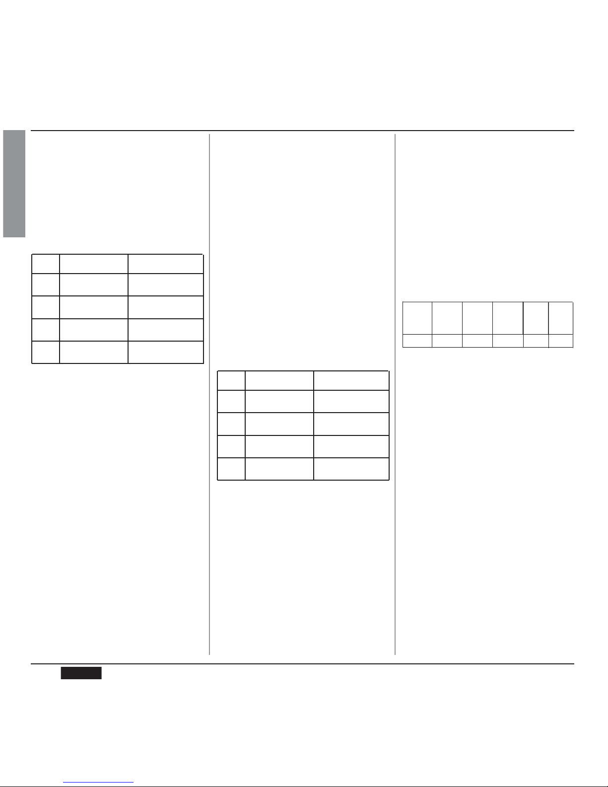
2 Gruppi 3 Gruppi 4 Gruppi
PESO NETTO
74 kg 136 lb 88kg 194 lb 104 kg 229 lb
PESO LORDO 80kg 176 lb 98 kg 216 lb 120 kg 264 lb
POT. TERMICA 4500 W 4500 W 5000 W 5000 W 5000 W 5000 W
DIMENSIONI 780 mm 30
¹⁄₄
” 1010 mm 39
⁵⁄₁₆
” 1240 mm 48
⁵⁄₁₆
”
635 mm 25” 865 mm 34” 1095 mm 43
¹⁄₁₆
”
540 mm 21
¹⁄₈
” 540 mm 21
¹⁄₈
” 540 mm 21
¹⁄₈
”
315 mm 12
³⁄₁₆
” 315 mm 12
³⁄₁₆
” 315 mm 12
³⁄₁₆
”
510 mm 20” 510 mm 20” 510 mm 20”
135 mm 5
¹⁄₈
” 135 mm 5
¹⁄₈
” 135 mm 5
¹⁄₈
”
180 mm 7
¹⁄₁₆
” 180 mm 7
¹⁄₁₆
” 180 mm 7
¹⁄₁₆
”
2
C
CARATTERISTICHE TECNICHE
D
E
A
B
F
G
A
B
F
G
C
D
E
A
B
F
G
C
D
E
A
B
F
G
C
D
E
A
B
F
G
C
D
E
A
B
F
G
C
D
E
A
B
F
G
C
D
E

ITALIANO
3
CARATTERISTICHE TECNICHE . . . . . . . .2
1.
DESCRIZIONE . . . . . . . . . . . . . . . . . . . . .5
1.1 LISTA ACCESSORI . . . . . . . . . . . . . . . . . . . . . . . . . . . .6
2.
PRESCRIZIONI DI SICUREZZA . . . . . . . .7
3.
TRASPORTO E MOVIMENTAZIONE . . . .10
3.1 IDENTIFICAZIONE MACCHINA . . . . . . . . . . . . . . . . .10
3.2 TRASPORTO . . . . . . . . . . . . . . . . . . . . . . . . . . . . . . .10
3.3 MOVIMENTAZIONE . . . . . . . . . . . . . . . . . . . . . . . . . .10
4.
INSTALLAZIONE E OPERAZIONI
PRELIMINARI . . . . . . . . . . . . . . . . . . . . .10
5.
REGOLAZIONI DEL
TECNICO QUALIFICATO . . . . . . . . . . . .12
5.1 RIEMPIMENTO MANUALE CALDAIA . . . . . . . . . . . .12
5.2 REGOLAZIONE PRESSOSTATO POMPA . . . . . . . . .12
5.3 REGOLAZIONE ECONOMIZZATORE
ACQUA CALDA . . . . . . . . . . . . . . . . . . . . . . . . . . . . .13
5.4 SOSTITUZIONE BATTERIA OROLOGIO
(SOLO PER VERSIONE VIP PLUS) . . . . . . . . . . . . . .13
5.5 SOSTITUZIONE DELLE PULSANTIERE . . . . . . . . . .13
5.6 GIORNALE ELETTRONICO . . . . . . . . . . . . . . . . . . . .13
6.
UTILIZZO . . . . . . . . . . . . . . . . . . . . . . .14
6.1 ACCENZONE DELLA MACCHINA . . . . . . . . . . . . . . .14
6.1.1 AURELIA VIP PLUS . . . . . . . . . . . . . . . . . . . . . . . . .14
6.1.2 AURELIA V/ESSE . . . . . . . . . . . . . . . . . . . . . . . . . . . .15
6.1.3 AURELIA VIP-V/ESSE CON
GIORNALE ELETTRONICO (OPTIONAL) . . . . . . . . . .15
6.2 CONFIGURAZIONE SELEZIONE . . . . . . . . . . . . . . . .16
6.3 PREPARAZIONE DEL CAFFE’ . . . . . . . . . . . . . . . . . .16
6.4 UTILIZZO DEL VAPORE . . . . . . . . . . . . . . . . . . . . . .16
6.5 PREPARAZIONE DEL CAPPUCCINO . . . . . . . . . . . .17
6.6 SELEZIONE ACQUA CALDA . . . . . . . . . . . . . . . . . . .17
6.7 LANCIA VAPORE TEMPORIZZATA . . . . . . . . . . . . .17
7.
PROGRAMMAZIONE . . . . . . . . . . . . . . . .18
7.1 LEGENDA . . . . . . . . . . . . . . . . . . . . . . . . . . . . . . . . . .18
7.2 PROGRAMMAZIONE AURELIA VIP PLUS . . . . . . . . .18
7.3 PROGRAMMAZIONE AURELIA V . . . . . . . . . . . . . . . .24
7.4 PROGRAMMAZIONE AURELIA ESSE . . . . . . . . . . . .27
8.
PULIZIA E MANUTENZIONE . . . . . . . . .28
8.1 ARRESTO . . . . . . . . . . . . . . . . . . . . . . . . . . . . . . . . . .28
8.2 PULIZIA DELLA CARROZZERIA . . . . . . . . . . . . . . . .28
8.3 PULIZIA DELLE DOCCETTE INOX . . . . . . . . . . . . . .28
8.4 PULIZIA DEL GRUPPO CON L’AUSILIO DE
FILTRO CIECO . . . . . . . . . . . . . . . . . . . . . . . . . . . . .28
8.5 PULIZIA DEI FILTRI E PORTAFILTRI . . . . . . . . . . . .28
8.6 RIGENERAZIONE DELLE RESINE
DELL’ADDOLCITORE . . . . . . . . . . . . . . . . . . . . . . . . .29
9.
MESSAGGI FUNZIONI MACCHINA
AURELIA PLUS . . . . . . . . . . . . . . . . . . .30
10.
MESSAGGI FUNZIONI MACCHINA
AURELIA V . . . . . . . . . . . . . . . . . . . . . . .32
11.
MESSAGGI FUNZIONI MACCHINA
AURELIA S . . . . . . . . . . . . . . . . . . . . . . .33
IMPIANTO ELETTRICO AURELIA S . . . .69
IMPIANTO ELETTRICO
AURELIA PLUS Rel 3.xx . . . . . . . . . . . .70
IMPIANTO ELETTRICO
AURELIA PLUS Rel 1.xx . . . . . . . . . . . .71
IMPIANTO ELETTRICO AURELIA V . . . .72
IMPIANTO IDRAULICO . . . . . . . . . . . . .73
INDICE

ITALIANO
4

ITALIANO
5
Fig. 1
LEGENDA
1 Manopola vapore
2 Chiave programmazione (solo Vip Plus)
3 Display LCD (solo Vip Plus)
4 Pulsanti funzione (solo Vip Plus)
5 Pulsanti selezione
6 Pulsanti gruppo erogatore
7 giornale elettronico (Optional)
8 Manopola vapore
9 Portafiltro
10 Targhetta dati
11 Lancia vapore manuale
12 Gruppo erogazione
13 Interruttore generale
14 Becco 2 caffè
15 Becco un caffè
16 Lancia vapore automatica (optional nelle
versioni V ed ESSE)
17 Livello ottico
18 Manometro
19 Piede regolabile
20 Lancia vapore manuale
21 Lancia acqua calda
22 Scaldatazze elettrico (Scaldatazze a vapo-
re optional)
18
17
15
10
9
8
11
13
1.
DESCRIZIONE Vip Plus - V - Esse
16 1214
2
4
63 75
21
20
22
1
19

ITALIANO
6
CODICE DESCRIZIONE 2 GRUPPI 3 GRUPPI 4 GRUPPI
A01 Tubo carico
³⁄₈
” 111
A02 Tubo scarico vaschetta gruppi Ø 20 mm - l. 150 cm 1 1 1
A03 Tubo scarico piano lavoro Ø 25 mm - l. 150 cm 1 1 1
A04 Portafiltro 3 4 5
A05 Filtro doppio 2 3 4
A06 Filtro singolo 1 1 1
A07 Filtro cieco 1 1 1
A08 Molla 3 4 5
A09 Becco erogazione doppio 2 3 4
A10 Becco erogazione singolo 1 1 1
A11 Pressa caffè 1 1 1
A12 Chiavi “U” e “T” (Solo modello plus) 1 1 1
Fig. 2
1.1
LISTA ACCESSORI
A11
A06
A07
A03
A02
A01
A05
A08
A04
A09
A10
A12

ITALIANO
7
Il presente libretto costituisce parte
integrante ed essenziale del prodotto
e dovrà essere consegnato all’utilizzatore. Leggere attentamente le
avvertenze contenute nel presente
libretto in quanto forniscono importanti indicazioni riguardanti la sicurezza di installazione, d’uso e manutenzione. Conservare con cura questo libretto per ogni ulteriore consultazione.
Dopo aver tolto l’imballaggio assicurarsi dell’integrità dell’apparecchio.
In caso di dubbio non utilizzare l’apparecchio e rivolgersi a personale
professionalmente qualificato. Gli
elementi dell’imballaggio (sacchetti
in plastica, polistirolo espanso, chiodi, ecc.) non devono essere lasciati
alla portata dei bambini in quanto
potenziali fonti di pericolo, né essere
dispersi nell’ambiente.
PERICOLO DI INQUINAMENTO
Prima di collegare l’apparecchio
accertarsi che i dati di targa siano
rispondenti a quelli della rete di dis-
In particolare dovrà anche accertare
che la sezione dei cavi dell’impianto
sia idonea alla potenza assorbita dall’apparecchio.
È vietato l’uso di adattatori, prese
multiple e prolunghe. Qualora il loro
uso si rendesse indispensabile è
necessario chiamare un elettricista
munito di patentino.
Durante l'installazione del dispositivo
devono essere utilizzati i componenti
e i materiali in dotazione al dispositivo stesso.
Qualora fosse necessario l'utilizzo di
altra componentistica, l'installatore
deve verificare l'idoneità dello stesso
ad essere utilizzato a contatto con
l'acqua per consumo umano.
Questo apparecchio dovrà essere
destinato solo all’uso descritto in
questo manuale. Il costruttore non
può essere considerato responsabile
per eventuali danni causati da usi
impropri, erronei ed irragionevoli.
Fig. 3
Fig. 4
2.
PRESCRIZIONI DI SICUREZZA
tribuzione elettrica. La targa è situata
sul frontale della macchina in alto a
destra. L’installazione deve essere
effettuata in ottemperanza alle norme
vigenti, secondo le istruzioni del
costruttore e da personale qualificato.
Il costruttore non può essere considerato responsabile per eventuali
danni causati dalla mancanza di
messa a terra dell’impianto. Per la
sicurezza elettrica di questo apparecchio è obbligatorio predisporre l’impianto di messa a terra, rivolgendosi
ad un elettricista munito di patentino,
che dovrà verificare che la portata
elettrica dell’impianto sia adeguata
alla potenza massima dell’apparecchio indicata in targa.
L’apparecchio non è idoneo per l’utilizzo da parte dei bambini, persone
con ridotte capacità fisiche, sensoriali o mentali, o carenti di conoscenze a
meno che non sia data supervisione
o istruzione.
Per gli apparecchi alimentati a 220230V, la massima impedenza fornita
dalla rete di alimentazione non deve
superare gli 0,37ohm.
L'installatore deve eseguire i collegamenti idraulici rispettando le norme
di igene e sicurezza idraulica di tutela ambientale vigenti nel luogo di
installazione. Quindi per l’impianto
idraulico rivolgersi ad un tecnico
autorizzato.
L'alimentazione del dispositivo deve
essere effettuata con acqua idonea al
consumo umano conforme alle disposizioni vigenti nel luogo di installazione. L'installatore deve acquisire
dal proprietario/gestore dell'impianto
conferma che l'acqua rispetti i requisiti sopra indicati.

ITALIANO
8
• non usare, prolunghe in locali adibiti a bagno o doccia;
• non tirare il cavo di alimentazione,
per scollegare l’apparecchio dalla
rete di alimentazione;
• non lasciare esposto l’apparecchio ad agenti atmosferici (pioggia, sole, ecc.);
• non permettere che l’apparecchio
sia usato da bambini, o da personale non autorizzato e che non
abbia letto e ben compreso questo
manuale.
Il tecnico autorizzato deve, prima di
effettuare qualsiasi operazione di
manutenzione, spegnere l'interruttore della macchina e aprire il sezionatore i fase.
Per le operazioni di pulizia attenersi
esclusivamente a quanto previsto nel
seguente libretto.
In caso di guasto o di cattivo funzionamento dell’apparecchio, spegnerlo. È severamente vietato intervenire.
All’installazione, l’elettricista munito
di patentino dovrà prevedere un
interruttore onnipolare come previsto
dalle normative di sicurezza vigenti
con distanza di apertura dei contratti
uguale o superiore a 3 mm.
Per evitare surriscaldamenti pericolosi si raccomanda di svolgere per
tutta la sua lunghezza il cavo di alimentazione.
Non ostruire le griglie di aspirazione
e/o di dissipazione in particolare
dello scaldatazze.
Il cavo di alimentazione di questo
apparecchio non deve essere sostituito dall’utente. In caso di danneggiamento, spegnere l’apparecchio e
per la sua sostituzione rivolgersi
esclusivamente a personale professionalmente qualificato.
Fig. 5
In fase di installazione la rete elettrica
dovrà essere predisposta con un
sezionatore che sezioni ogni fase.
Rivolgersi esclusivamente a personale professionalmente qualificato.
L’eventuale riparazione dei prodotti
dovrà essere effettuata solamente
dalla casa costruttrice o da centro di
assistenza autorizzato utilizzando
esclusivamente ricambi originali.
Il mancato rispetto di quanto sopra
può compromettere la sicurezza dell’apparecchio.
Gli apparecchi monofase con corrente superiore a 15A e gli apparecchi
trifase venduti senza spina sono collegati all’impianto di alimentazione
elettrica direttamente tramite il cavo;
non è possibile quindi, l’utilizzo di
una spina.
L’uso di un qualsiasi apparecchio
elettrico comporta l’osservanza di
alcune regole fondamentali.
In particolare:
• non toccare l’apparecchio con
mani o piedi bagnati;
• non usare l’apparecchio a piedi
nudi;
ATTENZIONE
PERICOLO DI SCOSSA ELETTRICA
Le temperature massime e minime di
immagazzinamento devono essere
comprese nel range [-5,+50]°C.
La temperatura di funzionamento
deve essere compresa nel range
[+5,
+35]°C.
Al termine dell'installazione, il dispositivo viene attivato e portato fino alla
condizione nominale di lavoro
lasciandolo in condizioni di “pronto
al funzionamento”.
Successivamente il dispositivo viene
spento e tutto il circuito idraulico
viene svuotato della prima acqua
immessa in modo da eliminare eventuali impurità iniziali.
In seguito il dispositivo viene nuovamente caricato e portato fino alle
condizioni
nominali di funzionamento.
Dopo il raggiungimento dello stato di
“pronto al funzionamento” si effettuano le seguenti erogazioni:
- 100% del circuito caffè attraverso l'erogatore caffè (per più erogatori si divida in uguale misura);
- 100% del circuito acqua calda attraverso l'erogatore acqua (per più erogatori si divida in uguale misura);
- apertura di ciascuna uscita vapore per
1 minuto
Al termine dell'installazione sarebbe
buona regola stilare un rapporto di
quanto effettuato.

ITALIANO
9
ATTENZIONE
PERICOLO DI INQUINAMENTO
Non disperdere la macchina nell’ambiente: per lo smaltimento rivolgersi
ad un centro autorizzato o contattare
il costruttore che darà indicazioni in
merito.
ATTENZIONE
PERICOLO DI INTOSSICAZIONE
Durante l’uso della lancia del vapore,
prestare molta attenzione e non mettere le mani sotto di esso e non toccarla subito dopo l’uso.
ATTENZIONE
PERICOLO DI USTIONE
Ricordare che prima di effettuare
qualsiasi operazione di installazione,
manutenzione, scarico, regolazione,
l’operatore qualificato deve indossare i guanti da lavoro e le scarpe antinfortunistiche.
Allorché si decida di non utilizzare
più un apparecchio di questo tipo si
raccomanda di renderlo inoperante
dopo aver staccato la spina, tagliare
il cavo di alimentazione.
Fig. 6
Fig. 7
INFORMAZIONE AGLI UTENTI
Ai sensi dell’ art. 13 del
Decreto Legislativo 25 luglio
2005, n. 151 “Attuazione delle
Direttive 2002/95/CE,
2002/96/CE e 2003/108/CE,
relative alla riduzione dell’
uso di sostanze pericolose nelle apparecchiature elettriche ed elettroniche, nonché
allo smaltimento dei rifiuti”.
Il simbolo del cassonetto barrato riportato sull’apparecchiatura indica che il prodotto alla fine
della propria vita utile deve essere raccolto
separatamente dagli altri rifiuti. L’ utente dovrà,
pertanto, conferire l’ apparecchiatura giunta a
fine vita agli idonei centri di raccolta differenziata dei rifiuti elettronici ed elettrotecnici, oppure riconsegnarla al rivenditore al momento dell’acquisto di una nuova apparecchiatura di tipo
equivalente, in ragione di uno a uno. L’ adeguata raccolta differenziata per l’ avvio successivo dell’ apparecchiatura dimessa al riciclaggio,al trattamento e allo smaltimento ambientalmente
compatibile contribuisce ad evitare possibili
effetti negativi sull’ ambiente e sulla salute e
favorisce il riciclo dei materiali di cui è composta l’ apparecchiatura. Lo smaltimento abusivo
del prodotto da parte dell’ utente comporta l’
applicazione delle sanzioni amministrative di
cui al D.Lgs.n.22/1997” (articolo 50 e seguenti
del D.Lgs.n.22/1997).
ATTENZIONE
Il massimo livello di disturbo sonoro
emesso è inferiore ai 70db.
Il tubo alla connessione idrica se
sostituito non deve essere più riutilizzato.

Una volta rimosso l’imballo e aver verificato l’integrità della macchina e degli accessori, procedere come descritto di seguito:
• posizionare la macchina su un piano orizzontale;
• assemblare i piedini di sostegno della macchina inserendo l’inserto all’interno del
guscio cilindrico;
• avvitare il piedino in gomma nella filettatura
dell’inserto contenuto nel guscio;
• avvitare tutto il gruppo assemblato nelle
apposite sedi di alloggiamento dei piedini
della macchina;
• mettere in piano la macchina agendo sui
piedini di regolazione;
NOTA: la scanalatura del guscio deve essere
rivolta verso l’alto, come indicato nella
figura successiva.
In fase preliminare, dopo la messa in piano
della macchina, si consiglia di installare un
addolcitore (1), all’uscita della rete idrica, e di
seguito un filtro a maglia (2).
Fig. 9
4.
INSTALLAZIONE
E OPERAZIONI
PRELIMINARI
10
ITALIANO
Per qualsiasi comunicazione con il costruttore
Nuova Simonelli, citare sempre il numero di
matricola della macchina.
La macchina viene trasportata in pallett con più
macchine dentro scatoloni assicurati al pallett
con delle centine.
Prima di procedere a qualsiasi operazione di
trasporto o movimentazione, l’operatore deve:
• indossare guanti e scarpe antinfortunistici
ed una tuta con elastici alle estremità.
Il trasporto del pallett deve essere effettuato
con un mezzo di sollevamento adeguato
(tipo muletto).
ATTENZIONE
PERICOLO DI URTO O SCHIACCIAMENTO
ATTENZIONE
PERICOLO DI URTO O SCHIACCIAMENTO
L’operatore durante tutta la movimentazione, deve avere l’attenzione che non ci siano
persone, cose od oggetti nell’area di operazione.
Sollevare lentamente il pallett a circa 30 cm
da terra e raggiungere la zona di carico.
Dopo aver verificato che non ci siano ostacoli, cose o persone, procedere al carico.
Una volta arrivati a destinazione, sempre
con un mezzo di sollevamento adeguato
(es. muletto), dopo essersi assicurati che
non ci siano cose o persone nell’area di
scarico, portare il pallett a terra e movimentarlo a circa 30 cm da terra, fino all’area di
immagazzinamento.
Prima della seguente operazione verificare
che il carico sia a posto e che con il taglio
delle centine non cada.
L’operatore con guanti e scarpe antinfortunistiche, deve procedere al taglio delle centine e allo stoccaggio del prodotto, in questa operazione consultare le caratteristiche
tecniche del prodotto per vedere il peso
della macchina da immagazzinare e potersi
regolare di conseguenza.
3.
TRASPORTO E MOVIMENTAZIONE
3.1
IDENTIFICAZIONE
MACCHINA
3.2
TRASPORTO
3.3
MOVIMENTAZIONE
Fig. 8

11
ITALIANO
Fig. 10
NOTA: Per un buon funzionamento della mac-
china occorre che la pressione di rete
non superi i 4 bar. In caso contrario,
installare un riduttore di pressione a
monte dell’addolcitore; il tubo in entrata
dell’acqua deve avere un diametro
interno non inferiore ai 6 mm (
³⁄₈
”).
LEGENDA
1 Addolcitore
2 Filtro a maglia
3 Scarico Ø 50 mm
ATTENZIONE
PERICOLO DI SCOSSA ELETTRICA
Prima di allacciare la macchina a una rete elettrica verificare che il voltaggio indicato sulla targhetta dati della macchina corrisponda a quello della rete.
In caso contrario, effettuare i successivi collegamenti sulla base della linea elettrica a disposizione, come illustrato successivamente:
• per voltaggio V 380 / 3 fasi +Neutro:
Fig. 11
Fig. 12
LEGENDA
1 Nero
2 Grigio
3 Marrone
La macchina deve essere sempre protetta
con un interruttore automatico onnipolare
di adeguata potenza con distanza di apertura dei contatti uguale o superiore a 3 mm.
La Nuova Simonelli non risponde di alcun
danno a cose o persone derivante dalla
mancata osservanza delle vigenti norme di
sicurezza.
Evitare strozzature nei tubi di collegamento.
Verificare inoltre che lo scarico (3) sia in
grado di eliminare gli scarti.
ATTENZIONE
2
3
1
• per voltaggio V 230 / monofase
4 Blu
5 Gialloverde
La pressione della rete idrica raccomandata
è [2,3] bar.
ATTENZIONE
Questo non permette alle impurità, come sabbia, particelle di calcare in sospensione, ruggine ecc., di danneggiare le delicate superfici in
grafite, garantendo una buona durata della
macchina. Dopo queste operazioni, provvedere
ai collegamenti idraulici come illustrato nella
seguente figura.
NOTA: All'inizio della attività giornaliera e
comunque nel caso in cui vi siano
pause maggiori di 8 ore bisogna procedere ad effettuare il ricambio del 100%
dell'acqua contenuta nei circuiti utilizzando gli erogatori preposti.
NOTA: In caso di esercizi in cui il servizio è
continuativo effettuare i ricambi di
sopra descritti almeno con frequenza
settimanale.

12
ITALIANO
Fig. 14
Fig. 17
Fig. 16
Fig. 15
5.
REGOLAZIONI DEL TECNICO QUALIFICATO
NOTA: operazione da eseguire a macchina
spenta.
Tutti i modelli sono muniti di sonda
di livello, per mantenere costante il livello di
acqua all’interno della caldaia.
E’ buona norma, al primo avviamento della
macchina, riempire manualmente la caldaia per
evitare che la resistenza elettrica si danneggi e
che inserisca la protezione elettronica.
Se questo dovesse accadere, è sufficiente spegnere la macchina e riaccenderla, per completarne il caricamento (vedi capitolo “MESSAGGI
FUNZIONE MACCHINA - ERRORE LIVELLO”).
Per effettuare il primo riempimento manuale,
agire come descritto di seguito:
• rimuovere la griglia del piano di lavoro;
• agire sul rubinetto livello manuale “A”, per
permettere l’ingrasso dell’acqua nella caldaia;
• raggiunto il livello minimo, indicato dal livello ottico, chiudere il rubinetto ”A”;
• accendere la macchina, posizionando l’in-
terruttore generale su “I”, in modo da attivare la sonda livello, che provvederà al mantenimento in modo automatico dell’acqua
nella caldaia.
NOTA: operazione eseguibile anche a macchi-
na accesa.
Per modificare la pressione di esercizio della
caldaia, quindi la temperatura dell’acqua, in
funzione delle varie esigenze o delle caratteristiche del caffè utilizzato, agire come descritto
di seguito:
• rimuovere la griglia del piano di lavoro;
• togliere la protezione in lamiera svitando le
due viti laterali (A) come illustrato nella
seguente figura;
5.1
RIEMPIMENTO
MANUALE CALDAIA
5.2
REGOLAZIONE
PRESSOSTATO / POMPA
• agire sulla vite di regolazione della pompa
per AUMENTARE (senso orario) oppure
DIMINUIRE (senso antiorario) la pressione;
• La pressione impostata della pompa viene
visualizzata nel settore inferiore del manometro.
Al termine delle regolazioni, riposizionare la
protezione in lamiera nell’apposito alloggiamento e fissarla con le quattro viti laterali; riposizionare la griglia del piano di lavoro.
• Agire sulla vite di regolazione della pompa
per AUMENTARE (senso orario) oppure
DIMINUIRE (senso antiorario) la pressione;
Valore consigliato: 1 - 1,4 bar
(secondo il tipo di caffè).
Valore consigliato: 9 bar.
Fig. 13
A
MAX
MIN
MAX
MIN
A

13
ITALIANO
NOTA: operazione eseguibile anche a macchi-
na accesa.
Tutti i modelli sono equipaggiati di
un miscelatore di acqua calda, il quale permette di regolare la temperatura di uscita dell’acqua e di ottimizzare il rendimento del sistema.
Per regolare l’economizzatore acqua calda,
agire sul pomello di registro come descritto di
seguito:
• svitare e rimuovere le quattro viti (A) di fissaggio del pannello situate sotto le leve
vapore e acqua calda;
• rimuovere il pannello;
Fig. 18
Fig. 19
5.3
REGOLAZIONE
ECONOMIZZATORE
ACQUA CALDA
• ruotare il pomello di registro in senso ORARIO / ANTIORARIO per AUMENTARE /
DIMINUIRE la temperatura dell’acqua calda;
5.4
SOSTITUZIONE
BATTERIA OROLOGIO
(solo per versione
Vip Plus)
La centralina elettronica della versione Vip
Plus, è provvista di una batteria al litio per l’alimentazione dell’orologio con autonomia di
circa tre anni, dopodichè può rendersi necessaria la sostituzione.
In caso di stop prolungato della macchina, l’orologio può essere bloccato con la seguente
procedura:
• con la macchina spenta, il display visualizza:
• mantenere premuto il tasto per 5
sec.; il display visualizza:
L’orologio si riavvierà appena la macchina sarà
collegata all’alimentazione elettrica.
5.5
SOSTITUZIONE DELLE
PULSANTIERE
La sostituzione della batteria al litio deve
essere eseguita SOLO dal Tecnico
Specializzato.
La Nuova Simonelli non risponde di alcun
danno a cose o persone, derivanti da una
mancata osservanza delle prescrizioni di
sicurezza, descritte in questo manuale.
Per un corretto funzionamento occorre, all’atto
della sostituzione, personalizzare ogni scheda
pulsantiera, agendo sui selettori posti sulla
scheda (lato tasti), così come sotto indicato.
ATTENZIONE
5.6
GIORNALE
ELETTRONICO
Come optional in ogni modello è previsto un
giornale elettronico programmabile con la
tastiera data in dotazione. Per la programmazione seguire le indicazioni fornite nell’apposito manuale.
• al termine dell’operazione rimontare il pannello protettivo con le apposite viti.
OFF
STOP OROLOGIO
A
GRUPPO sw1 sw1 sw1 sw1 sw1 sw1 sw1 sw1
Gruppo 1 On Off Off Off On Off Off Off
Gruppo 2 Off On Off Off Off On Off Off
Gruppo 3 Off Off On Off Off Off On Off
Gruppo 4 Off Off Off On Off Off Off On

14
ITALIANO
L’operatore deve prima di iniziare la lavorazione, accertarsi di aver letto e ben compreso le
prescrizioni di sicurezza di questo manuale.
Il modello Aurelia Vip Plus è dotato di una
chiave visualizzazione T e una chiave tecnico U; come optional è disponibile un sistema di gestione chiavi cameriere, pertanto
alle differenti chiavi corrispondono diverse
funzioni. Con le chiavi cameriere e visualizzazione T si può accedere alle normali funzioni di lavoro e possono essere visualizzati ma non modificati i menù della programmazione (Cap. 7).
La chiave tecnico U permette di accedere a
tutte le funzioni e di modificare i parametri
dei menu di programmazione.
6.1
ACCENSIONE
DELLA MACCHINA
Fig. 20
Fig. 21
6.1.1 AURELIA VIP PLUS
• Collegare la macchina alla presa elettrica e
posizionare l’interruttore generale in posizione “I”.
• Lo stato di macchina in funzione viene indicato dalla relativa spia:
• Sul display, non illuminato, compare la scritta:
NOTA: La macchina non è operativa, in quan-
to l’interruttore generale permette solo
l’alimentazione della scheda elettronica.
In caso di manutenzione alla scheda elettronica, spegnere la macchina tramite l’interruttore generale esterno o scollegare il cavo
di alimentazione.
ATTENZIONE
ACCENSIONE / SPEGNIMENTO MANUALE
On - Off Automatico NON PROGRAMMATO
NOTA: assicurarsi che l’interruttore generale
sia sempre in posizione “I”.
Lo stato di macchina in funzione viene
indicato dalla relativa spia:
OFF
6.
UTILIZZO
ACCENSIONE: premere il tasto per 2
sec., il cicalino emette un bip,
il display si illumina indicando
la release della Eprom per
circa 1 secondo.
La centralina effettua l’autodiagnosi delle funzioni, tutti i tasti
di selezione si illuminano.
Terminata la diagnosi, sul display compare la scritta:
con giorno e ora. Raggiunta la
temperatura di 110°C, la scritta riscaldamento scompare,
sostituita da:
NOTA: tutti i tasti di selezione sono abilitati sin
dalla fine della diagnosi.
SPEGNIMENTO: premere il tasto per 2
secondi la macchina si spegne
e sul display è indicato:
Nel caso in cui l’autodiagnosi indichi anomalie o guasti, chiamare il centro di assistenza, l’operatore NON DEVE intervenire.
ATTENZIONE
RISCALDAMENTO
MACCHINA PRONTA
OFF

15
ITALIANO
On - Off Automatico PROGRAMMATO
NOTA: assicurarsi che l’interruttore generale
sia sempre in posizione “I”.
Lo stato di macchina in funzione viene
indicato dalla relativa spia:
La macchina si ACCENDERA’ al primo orario di accensione programmato (vedi capitolo PROGRAMMAZIONE e paragrafo PROGRAMMAZIONE ON - OFF).
La centralina effettua l’autodiagnosi delle funzioni, tutti i tasti
di selezione si illuminano.
Terminata la diagnosi, sul display compare la scritta:
con giorno e ora. Raggiunta la
temperatura di 110°C, la scritta riscaldamento scompare,
sostituita da:
NOTA: tutti i tasti di selezione sono abilitati sin
dalla fine della diagnosi.
6.1.2 AURELIA V/ESSE
ACCENSIONE: collegare la macchina alla
presa elettrica e premere l’interruttore generale in posizione “I”.
Lo stato di macchina in funzione viene indicato dalla
relativa spia:
Nel caso in cui l’autodiagnosi indichi anomalie o guasti, chiamare il centro di assistenza, l’operatore NON DEVE intervenire.
Nel caso in cui l’autodiagnosi indichi anomalie o guasti, chiamare il centro di assistenza, l’operatore NON DEVE intervenire.
La macchina si SPEGNERA’ al primo orario
di spegnimento programmato (vedi capitolo
PROGRAMMAZIONE e paragrafo PROGRAMMAZIONE ON - OFF).
NOTA: La macchina può essere accesa o
spenta manualmente come indicato nel
paragrafo precedente.
Fig. 22
SPEGNIMENTO: premere l’interruttore gene-
rale in posizione “O” per
spengere la macchina e la
relativa spia.
6.1.3 AURELIA VIP-V/ESSE CON
GIORNALE ELETTRONICO
(OPTIONAL)
ACCENSIONE: collegare la macchina alla
presa elettrica e premere l’interruttore “A” in posizione “I”,
la macchina si accende.
Premendo l’interruttore “B” in
posizione “I” si accende il display luminoso a macchina
spenta.
ATTENZIONE
ATTENZIONE
Fig. 23
Nel caso in cui l’autodiagnosi indichi anomalie o guasti, chiamare il centro di assistenza, l’operatore NON DEVE intervenire.
ATTENZIONE
RISCALDAMENTO
MACCHINA PRONTA

16
ITALIANO
ATTENZIONE
PERICOLO DI USTIONE
6.2
CONFIGURAZIONE
SELEZIONE
Impostare la funzione desiderata sui tasti a disposizione posti sopra i portafiltri (Vedi capitolo
“DESCRIZIONE”).
Fig. 24
LEGENDA TASTI
(Configurazione selezioni)
1 Caffè corto
2 Caffè corto
1 Caffè lungo
2 Caffè lungo
Continuo
6.3
PREPARAZIONE DEL
CAFFE’
Sganciare il portafiltro e riempire di una o due
dosi di caffè macinato a seconda del filtro utilizzato.
Fig. 25
Pressare il caffè con l’apposito pressino in
dotazione, pulire dai residui di polvere di caffè il
bordo anulare del filtro (per garantire una
migliore tenuta e un’inferiore usura della guarnizione).
Innestare quindi il portafiltro nel gruppo.
Premere il pulsante caffè desiderato:
Si attiva la pompa e si apre l’elettrovalvola del
gruppo dando avvio all’infusione del caffè.
L’ operazione è evidenziata dall’accensione del
tasto premuto.
NOTA: nelle fasi di pausa, lasciare il portafiltro
innestato al gruppo affinchè rimanga
sempre caldo.
I gruppi di erogazione sono termocompensati a circolazione totale di acqua
calda, per garantire la massima stabilità termica durante l’esercizio.
Per utilizzare il vapore è sufficiente tirare o
spingere l’apposita leva (Fig. 26).
Tirando completamente, la leva rimane bloccata nella posizione di massima erogazione, spingendo, il ritorno della leva è automatico.
Le due lance vapore sono snodate, consentendo un più agevole utilizzo delle stesse.
6.4
UTILIZZO DEL VAPORE
Fig. 26
Durante l’uso della lancia del vapore, prestare molta attenzione a non mettere le
mani sotto di essa e non toccarla subito
dopo.
1 Caffè corto
2 Caffè corto
1 Caffè lungo
2 Caffè lungo
NOTA: L'utilizzo della lancia vapore deve esse-
re sempre preceduta dall'operazione di
spurgo della condensa per almeno 2
secondi o seguendo le istruzioni del
costruttore.

17
ITALIANO
6.5
PREPARAZIONE DEL
CAPPUCCINO
Per ottenere la tipica schiuma immergere il
beccuccio del vapore in fondo al recipiente
pieno per 1/3 (preferibilmente a forma troncoconica). Aprire il vapore. Prima che il latte abbia
raggiunto lo stato di ebollizione, spostare il beccuccio del vapore in superficie facendo sfiorare
il latte con piccoli spostamenti in senso verticale. Alla fine dell’operazione pulire accuratamente la lancia con un panno morbido.
Fig. 27
6.6
SELEZIONE ACQUA
CALDA
ATTENZIONE
PERICOLO DI USTIONE
Durante l’uso della lancia dell’acqua calda,
prestare molta attenzione a non mettere le
mani sotto di essa e non toccarla subito
dopo.
Consente l’erogazione di acqua calda per preparare thè, camomilla e tisane.
Posizionare sotto la lancia acqua calda un contenitore (vedi Fig. 1 posizione 21).
Premere una volta sul pulsante selezione
acqua calda .
Assicurarsi che il pulsante stesso si illumini.
Dalla lancia acqua calda verrà erogata acqua
per un tempo equivalente al valore programmato.
NOTA: L’erogazione dell’acqua calda può
avvenire contemporaneamente a quella del caffè .
6.7
LANCIA VAPORE
TEMPORIZZATA
ATTENZIONE
PERICOLO DI USTIONE
Durante l’erogazione del vapore, non toccare con le parti del corpo la lancia, quindi
mantenerla sempre inclinata verso il basso
sulla griglia porta tazza.
Consente l’erogazione del vapore per emulsionare il latte, oppure per riscaldare altri liquidi.
Posizionare sotto la lancia vapore automatica
(vedi Fig. 1 posizione 16) un contenitore adatto.
Premere una volta sul pulsante selezione vapore .
Assicurarsi che il pulsante stesso si illumini.
Dalla lancia vapore automatico uscirà vapore
Ripremerlo per interrompere l’erogazione.
Nei modelli Plus e V è disponibile come optional la lancia con sonda di temperatura che
rimane aperta fino a che la bevanda che si
vuole riscaldare raggiunge la temperatura
impostata.

18
ITALIANO
CICLO AUTOMATICO DI PULIZIA
(funzione disponibile anche con chiave visualizzazione T)
• Premere il tasto per entrare in programmazione, il display visualizza:
• Premere e sul display verrà visualizzato:
• Il tasto centrale di ogni gruppo comincerà a lampeggiare. Inserire il filtro cieco
(fig2 A07) nel portafiltro, aggiungere mezza
dose di pulicaff e agganciare il portafiltro al
gruppo sul quale si vuole procedere con il
lavaggio automatico. E’ possibile effettuare
il lavaggio anche in più gruppi contemporaneamente.
• Premere il tasto per avviare il ciclo
di pulizia automatico sul gruppo. Sul
display comparirà:
dove 1L indica che nel 1° gruppo è stato
attivato il ciclo di lavaggio. Terminato il ciclo
di 15 erogazioni da 5 secondi l’una, con
una pausa fra le erogazioni di 10 secondi, il
tasto del gruppo selezionato torna a
lampeggiare e sul display comparirà .
RISCIACQUARE
CICL.AUT.PULIZIA
CICL.AUT.PULIZIA
SELEZIONA
Tasto RESET per accendere e spegnere la macchina e per uscire dal
menù.
7.
PROGRAMMAZIONE
7.1
LEGENDA
Serratura chiave tecnico/cameriere.
Tasto CURSORI: scorrimento dei menù e incremento e decremento dei
valori.
Tasto ENTER: per accedere all’interno del menù.
LISTA FUNZIONI PROGRAMMABILI
CICL. AUT. PULIZIA
PROGRAM. DOSI
CONT. EROGAZIONI
PROGRAMM. ON/OFF
PRO. SCALDATAZZE
DATA/ORA
MACINATURA
STORICO ALLARMI
MANUTENZIONE
LINGUA
TEMPERATURA
REG. LUMINOSITA’
Operazione eseguibile SOLO da
Tecnico Specializzato.
La regolazione da parte di Tecnici
NON qualificati o di altre persone
potrebbe invalidare la garanzia.
7.2
PROGRAMMAZIONE
Aurelia Vip Plus
Per entrare negli ambienti di programmazione,
operare come descritto:
NOTA: operazione eseguibile a macchina
accesa.
• Inserire la chiave contrassegnata con U
(vedi capitolo “UTILIZZO”) nell’apposita serratura.
Fig. 28
2
1
3
4
5
6
1
Display LCD.
2
3
4
6
5
CICL.AUT.PULIZIA
1L

19
ITALIANO
(optional) la centralina riconosce automaticamente la presenza della sonda e sul display comparirà la scritta:
seguita dal valore già impostato dalla casa
costruttrice.
Premere i tasti per variare
la temperatura che deve raggiungere la
bevanda da riscaldare. Raggiunta tale temperatura si fermerà automaticamente l’erogazione del vapore.
• Nella versione standard (senza sonda di
temperatura) premendo il tasto sul
display comparirà la scritta:
seguita dal valore già impostato dalla casa
costruttrice.
Premere con i tasti per
variare il tempo di fuoriuscita del vapore da
erogare.
• Se si intende fare un nuovo campionamento premere nuovamente il pulsante .
Inizia l’erogazione. Quando la dose desiderata è raggiunta premere di nuovo il pulsante .
• Sul display viene visualizzato il nuovo valore da noi impostato ancora modificabile
selezionando i tasti .
• Premere il tasto o passare a una
successiva selezione per concludere l’operazione.
Il pulsante si spegne.
• Sul display verrà visualizzato il nuovo valore che sarà ancora possibile modificare con
i tasti .
• Passando alla successiva selezione o premendo il tasto .
Il tasto caffè programmato si spegne.
PROGRAMMAZIONE DOSI
• Premere due volte il tasto per entrare in programmazione, il display visualizza:
• Premere e sul display verrà visualizzato:
Tutti i tasti programmabili cominceranno a
lampeggiare.
• Premere il tasto caffè da programmare, il
display visualizza:
Seguita dal valore già programmato dalla
casa costruttrice.
• Variare la dose, agendo con i pulsanti
.
• Premendo il tasto caffè da programmare,
inizierà l’erogazione (nel frattempo tutti gli
altri tasti si spegneranno).
• Scegliere la dose di caffè erogata e quindi
premere nuovamente il tasto caffè da programmare.
• Svuotare il filtro ceco da eventuali residui di
pulicaff e premere il tasto per avviare
il ciclo di risciacquo nel gruppo o nei gruppi
in cui è stato eseguito il lavaggio. Nel display la lettere R rimane fissa cosi come il
tasto . Terminato il ciclo di risciacquo
del gruppo o dei gruppi selezionati, nel display compare la scritta:
MACCHINA PRONTA
VOLUME C.C:
PROGRAM.DOSI
PROGRAM.DOSI
SELEZIONA
ACQUA CALDA
• Premere il pulsante e assicurarsi che
lo stesso si illumini.
Sul display comparirà la scritta:
seguita dal valore già impostato dalla casa
costruttrice.
Premere i tasti per variare il tempo di fuoriuscita dell’acqua calda da
versare.
• Se si intende fare un nuovo campionamento premere nuovamente il pulsante .
Inizia l’erogazione. Quando la dose desiderata è raggiunta premere di nuovo il pulsante .
• Sul display viene visualizzato il nuovo valore da noi impostato ancora modificabile
selezionando i tasti .
• Premere il tasto o passare ad una
successiva selezione per concludere l’operazione.
Il pulsante si spegne.
VAPORE TEMPORIZZATO
• Premere il pulsante e assicurarsi
che lo stesso si illumini.
Nelle versioni con sonda di temperatura
SECONDI
SEC.VAP.
TEMP.VAP. °C

20
ITALIANO
DOSI STANDARD
• Quando sul display viene visualizzato:
intendiamo richiamare i valori delle dosi
standard.
• Premere il tasto .
Sul display viene visualizzato:
Ancora una volta i pulsanti erogazione (vedi
Fig. 29) cominceranno a lampeggiare.
• Selezionare uno o più tasti continui (il tasto/i
selezionati rimarranno a luce fissa).
Il tasto/i richiameranno i valori delle dosi
standard ai gruppi selezionati.
• Premere il tasto per confermare .
Sul display viene visualizzato:
NOTA: tutte le selezioni possono essere pro-
grammate per un tempo massimo di
erogazione di due minuti, dopodichè
compare la scritta (lampeggiante) sul
display:
CONTEGGIO EROGAZIONE
• Sul display è visualizzato:
• Premere il tasto per confermare.
A questo punto sul display viene visualizzato:
• Premere il tasto o per
uscire senza confermare.
TRASFERIMENTO DOSI
• Quando il display visualizza:
premendo il tasto si ha la possibilità di trasferire il valore delle dosi programmate agli altri gruppi.
Sul display verrà visualizzato:
a questo punto tutti i pulsanti erogazione dei
singoli gruppi lampeggiano come in Fig. 29.
• Selezionando il tasto continuo una
volta sul primo gruppo (il tasto da lampeggiante diventa a luce fissa), si trasferiscono
i valori programmati del primo gruppo agli
altri gruppi.
Fig. 29
PROGRAM.
DOSI SELEZIONA
TRASFERIME. DOSI
SELEZIONA GRUPPI
TRASFERIME. DOSI
SELEZIONA GRUPPI
DOSI STANDARD
SELEZIONA GRUPPI
PROGRAM.
DOSI SELEZIONA
• Premendo il tasto sul display apparirà:
• Tutti i tasti erogazione cominciano a lampeggiare. Premendo uno dei tasti erogazione si visualizza il numero delle relative erogazioni effettuate.
• Per azzerare premere il tasto .
NOTA: Il caffè continuo è conteggiato pari a
un’erogazione.
• Premere per accedere ai conteggi
per cameriere (se previsto).
• Premere il tasto e sul display verrà
visualizzato:
I tasti di caffè corto di tutti i gruppi
cominciano a lampeggiare.
Esempio:
Selezionando un tasto del primo gruppo (il
testo selezionato rimarrà acceso permanente) sul display comparirà la scritta:
che stà a indicare il totale delle erogazioni
effettuate da quel gruppo.
• Per azzerare premere .
• Per accedere ai conteggi per cameriere premere .
• Quando sul display verrà visualizzato:
premere e sul display verrà visualizzato:
PROGRAM.
DOSI SELEZIONA
ERRORE
CONT. EROGAZIONI
TOTALE SELEZIONE
TOTALE GRUPPO
TOTALE GRUPPO
EROG. 1°GR.
TOTALE GRUPPO

21
ITALIANO
• Premere per confermare e per passare al tempo di scaldatazze OFF, compreso tra 0 e 60 min.
NOTA: Programmando uno dei due valori
ON/OFF a 0 la funzione viene automaticamente esclusa.
Quando lo scaldatazze è programmato, il
pulsante lampeggia lentamente.
• Premere il tasto per passare alla
pagina successiva.
PROGRAMMAZIONE DATA/ORA
• Sul display è visualizzato:
• Premendo il tasto , il display visualizzerà per esempio:
Le ore cominceranno a lampeggiare.
• Variare le ore e i minuti utilizzando i tasti
.
• Confermare premendo il tasto .
Una volta variati le ore e i minuti premere
nuovamente e variare il giorno, il
mese e l’anno utilizzando la procedura
sopra descritta.
Al termine premere per passare
alla pagina successiva.
Questo valore indica il numero totale di erogazioni effettuate.
• Per azzerare premere .
• Per accedere ai conteggi totali per cameriere premere .
• Premendo il tasto sul display appare:
per accedere al conteggio dei lavaggi automatici premere .
• Nella macchina lampeggiano i tasti ,
premendo il tasto del gruppo si visualizza il
numero di cicli di lavaggio effettuati.
Mantenendo premuto il tasto (reset) per 5
secondi si azzera il contatore.
PROGRAM. ON/OFF
• Sul display è visualizzato:
• Premendo il tasto , il display visualizzerà:
i valori di ON e OFF indicano l’ora di accensione e spegnimento.
• Premere per passare ai
giorni successivi o precedenti.
• Premere per variare l’orario programmato per l’accensione (la scritta ON
07:30 comincerà a lampeggiare).
• Utilizzare i tasti per variare l’orario di accensione.
• Premere per confermare e per passare all’orario programmato per lo spegnimento (la scritta OFF 23:30 comincerà a
lampeggiare).
• Utilizzare i tasti per variare l’orario di spegnimento.
• Confermare, premendo .
• Per disabilitare l’accensione e lo spegnimento nel giorno di riposo settimanale, premere .
Sul display verrà visualizzato:
(per ripristinare, premere )
Dopo la Domenica, premendo ancora
un bip indica il passaggio alla pagi-
na successiva.
PROGRAMMAZIONE SCALDATAZ-
ZE
• Sul display è visualizzato:
• Premendo il tasto , il display visualizzerà per esempio:
La scritta ON 05 comincerà a lampeggiare,
con i tasti variare il tempo
di scaldatazze aperto (compreso tra 0 e 60
min).
RIPOSO SETTIMAN.
TOTALE MACCHINA
PROGRAM. ON-OFF
LUNEDI’
ON 07:30 OFF 23.30
CONTAT.LAVAGGI
PRO. SCALDATAZZE
ON05 OFF60
DATA/ORA
LUNEDI 08:22
08 MAGGIO 2003

22
ITALIANO
Premendo il tasto sul display verrà
visualizzato:
dove 00-40 indica il tempo massimo
(espresso in secondi) di erogazione di una
quantità campione di caffè, pari a 10 cc. per
il caffè singolo e 30 cc. per il caffè doppio.
Il primo valore inizierà a lampeggiare; modificarlo utilizzando i tasti .
Confermare premendo il tasto .
• Premere nuovamente il tasto per
passare al valore successivo.
Per modificare il valore procedere come
sopra descritto.
NOTA: Se il sistema rileva un tempo di eroga-
zione (della quantità campionata) inferiore al minimo programmato, sul display verrà visualizzato:
(Vedi capitolo “MESSAGGI FUNZIONI
MACCHINA”) quindi si dovrà intervenire sul macinino, diminuendo il grado di
macinatura.
Se il sistema rileva un tempo di erogazione (della quantità campionata)
superiore al massimo programmato,
verrà visualizzato sul display:
PROGRAMMAZIONE CONTROLLO
MACINATURA
Il modello Aurelia Plus è dotato di un sistema elettronico in grado di controllare il
tempo di erogazione dipendenti dalla macinatura del caffè.
• Sul display è visualizzato:
• Premendo il tasto sulla riga superiore compare :
e in quella inferiore lo stato attuale
Con i tasti si cambia il valore, con il tasto si esce senza confermare, mentre con il tasto si conferma.
Se la visualizzazione del tempo di erogazione è:
viene saltata la sottopagina per i valori del
controllo di macinatura e si passa direttamente alla pagina:
Se la visualizzazione del tempo di erogazio-
MACIN. FINE
MACINATURA
TEMPO DI EROGAZ.
TEMPO DI EROGAZ.
ATTIVO
TEMPO DI EROGAZ.
NON ATTIVO
TEMPO DI EROGAZ.
ATTIVO
STORICO ALLARMI
ne è attiva quando viene fatta partire una
erogazione, tranne che con il Continuo, la
riga inferiore del Display viene adibita alla
visualizzazione del tempo di erogazione (o
dei tempi se più gruppi stanno erogando).
Ad ogni gruppo è riservata una zona della
riga inferiore: la zona a sinistra è per il gruppo 1, quella di fianco per il gruppo 2 così via
fino alla zona più a destra per il gruppo 4.
Le varie zone sono separate da barre verticali; se un gruppo non sta erogando la zna
viene lasciata vuota,
Di seguito è riportato un esempio: sono in
erogazione il gruppo 1(è appena partito
sono trascorsi 0 secondi), il gruppo 2 (sta
erogando da 12 secondi), ed il gruppo 4 (sta
erogando da 21 secondi).
Se si conferma il tempo:
si passa all’impostazione dei valori del controllo di macinatura.
MACIN. GROSSA
GIOVEDI 12:00
0 I 12 I I 21
Zona riservata al tempo
di erog. del gruppo 1
Zona riservata al tempo
di erog. del gruppo 4
Zona riservata al tempo
di erog. del gruppo 2
Zona riservata al tempo
di erog. del gruppo 3
TEMPO DI EROGAZ.
NON ATTIVO
1 CAFFE’ 00-40
2 CAFFE’ 00-40

23
ITALIANO
• Utilizzare i tasti per impostare entrambi i valori.
• Utilizzare il tasto per confermare.
Raggiunto il limite impostato di erogazioni o
raggiunta la data fissata per la manutenzione sul display comparirà la scritta:
Inserire la chiave “U” (vedi capitolo “UTILIZZO”) e azzerare il display premendo il tasto
.
Per passare alla pagina successiva premere il tasto .
SELEZIONE LINGUA
• Sul display è visualizzato:
• Premendo il tasto , sul display verrà
visualizzata la lingua già impostata.
Scegliere la lingua desiderata utilizzando i
tasti .
• Confermare premendo .
SCELTA UNITA’ DI MISURA TEMPERATURA
• Sul display è visualizzato:
• Premendo il tasto , il display visualizza:
(Vedi capitolo “MESSAGGI FUNZIONI
MACCHINA”) quindi si dovrà intervenire sul macinino, aumentando il grado di
macinatura. Programmando i valori a
00-40, la funzione viene esclusa.
• Al termine premere per passare
alla pagina successiva.
VISUALIZZAZIONE STORICO
ALLARMI
• Sul display è visualizzato:
• Premendo il tasto , il display visualizzerà:
• Premendo il tasto si scorrono gli
ultimi dieci allarmi memorizzati. Dopo il
decimo allarme, premendo di nuovo il tasto
si passa alla pagina successiva.
PROGRAMMAZIONE MANUTENZIONE
• Sul display è visualizzato:
• Premendo il tasto , il display visualizzerà:
STORICO ALLARMI
ERRORE 01
MANUTENZIONE
MANUTENZIONE
LINGUA
EROGAZIONI 10000
01 GENNAIO 2005
TEMPERATURA
CELSIUS
O
• Con i tasti è possibile modificare l’unità di misura impostata.
• Confermare premendo .
REGOLAZIONE LUMINOSITA'
TASTIERA
• Sul display è visualizzato:
• Premendo il tasto , sul display verrà
visualizzato:
• Con la scritta “
p
pulsanti X”
lampeggiante,
scegliere il valore di luminosità desiderato
da un valore minimo di 1 a un massimo di 6
utilizzando i tasti .
• Confermare premendo .
• Il valore della luminosità “
display Y”
lampeggia e utilizzando i tasti è
possibile impostare la luminosità della scritta “
display Y”
da un minimo di 1 ad un
massimo di 3.
• Confermare premendo il tasto .
• Sul display verrà visualizzato:
FAHRENEIT
PULSANTI X
DISPLAY Y
REG.LUMINOSITA’
REG.LUMINOSITA’

24
ITALIANO
PROGRAMMAZIONE DOSI
Per entrare negli ambienti di programmazione,
operare come descritto:
NOTA: Operazione eseguibile a macchina
accesa.
• Per entrare nello stato di programmazione
dosi di ogni gruppo è necessario premere
per 5 sec. il tasto erogazione continua
del primo gruppo.
• I tasti erogazione cominceranno a lampeggiare.
• L’accesso alla programmazione del primo
gruppo abilita anche l’impostazione dei
parametri di funzionamento della macchina.
PROGRAMMAZIONE DOSI CAFFE’
Per programmare la dose di acqua relativo a
uno dei tasti erogazione, procedere come
segue:
• riempire con la giusta dose di caffè il portafiltro (il portafiltro può essere singolo o doppio, a seconda del tasto che si desidera programmare).
• Immettere il portafiltro nel gruppo.
• Premere uno dei pulsanti erogatori (vedi
figura):
• L’erogazione ha inizio, una volta raggiunta
la quantità desiderata premere il tasto continuo .
7.3
PROGRAMMAZIONE
AURELIA V
• L’erogazione si arresta e il tasto dose scelto
si spegne (gli altri tasti continuano a lampeggiare).
• Premere il tasto continuo per uscire
dalla programmazione o continuare la programmazione di altri tasti dose.
NOTA: Questa procedura è utilizzabile per tutti
i gruppi della macchina a eccezione
che venga effettuata un gruppo alla
volta, gli altri gruppi possono continuare a operare normalmente.
PROGRAMMAZIONE ACQUA CALDA
• Entrare in programmazione secondo la relativa procedura.
• Premere il tasto selezione acqua calda
.
• L’erogazione dell’acqua calda ha inizio.
• Stabilire la dose di acqua calda desiderata e
premere nuovamente il tasto .
• Premere il tasto continuo per uscire
dalla programmazione o continuare la programmazione di altri tasti selezione.
Tecnico: Per attivare la pompa durante l'ero-
gazione dell'acqua calda entrare in programmazione del primo gruppo, poi premere il tasto continuo del secondo
gruppo.
• Per modificare l'impostazione è sufficiente
premere il tasto acqua calda ; se il
tasto è spento, durante l'erogazione di
acqua calda la pompa non viene attivata, se
il tasto è acceso durante l'erogazione di
acqua calda viene attivata la pompa.
• Premere il tasto continuo del secondo
gruppo per confermare l'impostazione.
PROGRAMMAZIONE SCALDATAZZE AUTOMATICO
• Entrare in programmazione secondo la relativa procedura.
• Premere il tasto selezione scaldatazze
.
• I pulsanti erogazione del primo e del secondo gruppo segnalano rispettivamente il
tempo di accensione e di spegnimento in
modalità automatica mentre lampeggiano i
tasti continuo del primo e del secondo gruppo.
Come descritto in tabella, ad ognuno dei
tasti erogazione è associato un valore, il
tempo di accensione dello scaldatazze è
dato dalla somma dei valori dei tasti del
primo gruppo illuminati.
La stessa modalità di conteggio avviene per
il tempo di spegnimento dello scaldatazze
con i tasti del secondo gruppo.
PROGRAMMAZIONE VAPORE TEMPORIZZATO
• Entrare in programmazione secondo la relativa procedura.
• Premere il tasto selezione vapore .
• L’erogazione di vapore ha inizio.
• Stabilire la dose di vapore desiderata e premere nuovamente il tasto .
• Per uscire dalla programmazione o continuare la programmazione di altri tasti selezione, premere il tasto continuo .

25
ITALIANO
REGOLAZIONE LUMINOSITA’
TASTIERA
• Entrare in programmazione del primo gruppo secondo la relativa procedura
• Premere il tasto erogazione continua
del secondo gruppo.
• Il tasto erogazione 2 caffè lungo del
secondo gruppo lampeggia.
• Premere il tasto più volte per cambiare l’intensità della luce.
NOTA: E’ possibile impostare al massimo cin-
que diversi livelli di luminosità.
• Per memorizzare i valori impostati di luminosità, premere il tasto erogazione continua
del secondo gruppo.
• Per uscire dalla programmazione, premere
il tasto erogazione continua del primo
gruppo.
NOTA: Le impostazioni vengono salvate anche
se si esce direttamente dalla programmazione del primo gruppo
Tasto
1° GRUPPO
(tempo ON)
2° GRUPPO
(tempo OFF)
2 minuti
4 minuti
5 minuti
10 minuti
8 minuti 20 minuti
16 minuti 40 minuti
ATTIVAZIONE POMPA AUTOLIVELLO
• Entrare in programmazione del primo gruppo secondo la relativa procedura.
• Premere il tasto erogazione continua
del secondo gruppo (il tasto si illumina).
• Premere il tasto 1 caffè corto del
secondo gruppo.
NOTA: Se il tasto 1 caffè corto è illumina-
to, la pompa si attiva durante il livello.
Se il tasto 1 caffè corto non è
illuminato, la pompa non si attiva
durante il livello.
• Premere il tasto erogazione continua
del secondo gruppo.
In questo modo viene memorizzata l’impostazione della pompa selezionata.
• Per uscire dalla programmazione, premere
il tasto erogazione continua del primo
gruppo.
NOTA: Le impostazioni viengono salvate
anche se si esce direttamente dalla
programmazione del primo gruppo.
LANCIA VAPORE CON SONDA DI
TEMPERATURA (OPTIONAL)
• Accertarsi che la sonda di temperatura sia
stata collegata alla centralina.
• Il valore di temperatura può essere inserito
per campionamento o manualmente e varia
da un minimo di 50°C ad un massimo di
95°C.
• Dopo essere entrati in programmazione del
1° gruppo, premere il tasto del 2°
gruppo.
L’ingresso nel sottomenu è segnalato dall’accensione del tasto del 2° gruppo.
• Tramite il tasto due caffè corti del 2°
gruppo, si imposta la memorizzazione della
temperatura del vapore per campionamen-
to, tasto acceso, oppure manuale, tasto
spento.
• Premendo il tasto si cambia la modalità di memorizzazione.
• Premere il tasto continuo del 2° gruppo, per memorizzare la modalità di inserimento della temperatura.
Campionamento:
• Dopo essere entrati in programmazione del
1° gruppo, inserire un bricco con il latte e
premere il tasto vapore , esso uscirà
dalla lancia.
• Premendo nuovamente il tasto vapore
la centralina memorizza la temperatura raggiunta nel campionamento. (Se la temperatura del latte raggiunge la temperatura massima, l’erogazione del vapore si ferma e
rimane impostato nella centralina il valore
massimo).
26
ITALIANO
Manuale:
• Dopo essere entrati in programmazione del
1° gruppo, premere il tasto vapore .
I tasti del 1°gruppo e del 2°gruppo, indicano
la temperatura partendo dal un valore minimo di 50°C.
• Ad ogni tasto è associato un valore:
• Facendo la somma del valore associato a
vari tasti illuminati si ottiene il valore della
temperatura, partendo dal valore minimo di
50°C.
• Se il tasto è acceso occorre sommare il
valore di riferimento, se il tasto è spento no.
• Premendo nuovamente il tasto vapore
si memorizza il valore e si ritorna allo
stato di programmazione generale.
In questa modalità di programmazione non
avviene l’erogazione.
• Per uscire dalla programmazione e salvare
il valore impostato, premere il tasto erogazione continua del 1° gruppo.
Tecnico:
• Nello stato di impostazione della temperatura vapore si può impostare un valore di offset, da -15°C a +15°C, per ottenere il valore corretto della temperatura.
• Tenendo premuto il tasto del 1° gruppo viene visualizzato il valore dell'offset
impostato:
la modalità è la stessa usata per la temperatura di fine erogazione del vapore.
• Tramite i tasti del 1° gruppo si rappresenta
un valore compreso da 0 a 15 °C, il tasto
del 2° gruppo segnala il segno dell'offset: se acceso si tratta di un valore
NEGATIVO, se spento di un valore POSITIVO.
• Rilasciando il tasto del 1° gruppo si
memorizza il dato e si ritorna all’impostazione della temperatura vapore.
Tasto
1° GRUPPO
2° GRUPPO
1 °C
2 °C
10 °C
20 °C
4 °C -
8 °C -
Tasto
1° GRUPPO
2° GRUPPO
1 °C
2 °C
+ o - °C
-
4 °C -
8 °C -
PROGRAMMAZIONE DOSI STANDARD
• E’ possibile impostare dei valori predetermnati per le quattro dosi del primo gruppo erogatore. Per fare ciò occorre:
• Premere il tasto erogazione continua
del primo gruppo e mantenerlo premuto per
almeno 8 secondi, fino a quando i tasti erogatori lampeggianti del primo gruppo si
spengono.
• Le dosi standard sono illustrate nella tabella
sottostante:
NOTA: Un tempo di 0 secondi per l’acqua e per
il vapore ne determina il funzionamento in continuo.
COPIATURA DOSI:
Questa operazione va effettuata singolarmente
a ogni gruppo premendo il tasto erogazione
continua del gruppo su cui si devono
copiare le dosi e mantenerlo premuto per almeno otto secondi fino a quando i tasti lampeggianti si spengono.
40 cc
60 cc 50 cc 85 cc 9 sec.
0 sec.

27
ITALIANO
REGOLAZIONE LUMINOSITA’
TASTIERA
• Entrare in programmazione secondo la relativa procedura.
• Regolare l’intensità della luce dei tasti premendo più volte il tasto del primo
gruppo.
NOTA: Per uscire dalla programmazione pre-
mere il tasto .
ATTIVAZIONE POMPA AUTOLIVELLO
• Entrare in programmazione secondo la relativa procedura.
• Premere e mantenere premuto il tasto
del secondo gruppo.
• Per impostare l'attivazione della pompa
durante l'autolivello, occorre, dopo essere
entrati nello stato di programmazione, man
tenere premuto il tasto del secondo
gruppo.
Il tasto del secondo gruppo si accende e tramite il tasto del primo gruppo
viene visualizzata l'impostazione della
pompa: se è acceso la pompa funziona
durante il livello, se è spento la pompa non
si attiva durante l'autolivello.
Premendo il tasto del primo gruppo
è possibile modificare l'impostazione della
pompa durante il livello.
NOTA: per uscire dalla programmazione è suf-
ficiente premere il tasto .
PROGRAMMAZIONE DOSI
Nella versione Aurelia Esse è possibile programmare solo la dose di acqua e vapore temporizzato.
Per entrare nello stato di programmazione è
necessario:
• premere per cinque secondi il tasto scaldatazze .
• I tasti selezione e il tasto del primo
gruppo cominciano a lampeggiare mentre
gli altri tasti erogazione degli altri gruppi si
spengono.
ACQUA CALDA
• Una volta entrati nello stato di programmazione, premendo il tasto si attiva
l'erogazione di acqua calda, raggiunta la
dose desiderata ripremere il tasto
e la centralina memorizza il tempo di erogazione impostato.
VAPORE TEMPORIZZATO
• Una volta entrati nello stato di programmazione, premendo il tasto si attiva
l'erogazione di acqua calda, raggiunta la
dose desiderata ripremere il tasto e
la centralina memorizza il tempo di erogazione impostato.
7.4
PROGRAMMAZIONE
AURELIA ESSE
CICLO AUTOMATICO DI PULIZIA
GRUPPI
• Per entrare nello stato di pulizia automatica
si deve spegnere la macchina e riaccenderla mantenendo premuti i tasti acqua
calda e scaldatazze durante il
Lamp-test iniziale. Al termine del Lamp-test
iniziano a lampeggiare i tasti , ed i
tasti un caffè lungo di tutti i gruppi.
• Premendo il tasto inizia il ciclo di
lavaggio del relativo gruppo. Terminato il
ciclo di lavaggio si può effettuare il ciclo di
risciacquo sullo stesso gruppo, ripremendo
il tasto .
• Se si vuole eseguire il ciclo di risciacquo in
un secondo momento è sufficiente spegnere la macchina: la scheda mantiene memorizzati i cicli di pulizia da terminare.
• Alla successiva accensione , infatti, la scheda entrerà automaticamente nello stato di
pulizia gruppi, senza premere i tasti
e .
• Premendo i tasti e per 2
secondi si esce dallo stato di pulizia nel
caso in cui non ci siano cicli da terminare,
altrimenti rimarranno lampeggianti i tasti
dei gruppi in cui si deve ancora ese-
guire il ciclo di risciacquo.
• Mantenendo i tasti e p e r
altri 2 secondi si forza l'uscita dallo stato di
pulizia azzerando l'informazione sui risciacqui da terminare.
• Se il ciclo di pulizia viene completato il tasto
del gruppo si spegne; se non ci sono
altri risciacqui da seguire la scheda esce
dallo stato di pulizia.

28
ITALIANO
Per arrestare la macchina bisogna ripremere l’interruttore generale e portarlo nella posizione O.
Prima di effettuare qualsiasi operazione di pulizia, bisogna portare la macchina a stato energetico “O” (cioè interruttore macchina spento e
sezionatore aperto).
Non utilizzare solventi, prodotti a base di
cloro, abrasivi.
Pulizia zona lavoro: togliere la griglia del pia-
nolavoro sollevandolo anteriormente verso l’alto e sfilarlo, togliere il sottostante piatto raccogliacqua e pulire il tutto con acqua calda e
detersivo. Pulizia carena: per pulire tutte le
parti cromate utilizzare un panno morbido inumidito.
8.1
ARRESTO
8.2
PULIZIA DELLA
CARROZZERIA
Fig. 30
Versione Aurelia
V/ESSE
Versione Aurelia
Vip/V/ESSE
8.
PULIZIA E MANUTENZIONE
ATTENZIONE
8.3
PULIZIA DELLE
DOCCETTE INOX
Le doccette inox sono situate sotto i gruppi erogazione, come si vede in figura (31).
Fig. 31
NOTA: Per la pulizia operare come descritto:
• Svitare la vite posta al centro della
doccetta.
• Sfilare la doccetta e verificare che i
fori non siano ostruiti.
• In caso di ostruzioni pulire secondo
descrizione (Paragrafo “PULIZIA DEI
FILTRI E PORTAFILTRI).
Si raccomanda di effettuare la pulizia
delle doccette settimanalmente.
ATTENZIONE
PERICOLO DI INTOSSICAZIONE
8.4
PULIZIA DEL GRUPPO
CON L’AUSILIO DEL
FILTRO CIECO
La macchina è predisposta per il lavaggio del
gruppo erogazione tramite detergente specifico
in polvere.
La macchina inizierà il ciclo di pulizia che consiste nel ricircolo di acqua calda intervallata da
un tempo di attesa.
E’ consigliabile effettuare il lavaggio almeno
una volta al giorno con gli appositi detergenti.
Una volta tolto il portafiltro effettuare alcune
erogazioni per eliminare eventuali residui di
detergente.
Per eseguire la procedura di lavaggio procedere come segue:
1) Sostituire il filtro con quello cieco del gruppo
erogatore.
2) Mettervi all’interno due cucchiai di detergente specifico in polvere e immettere il portafiltro al gruppo.
3) Premere uno dei tasti caffè e arrestare dopo
10 sec. .
4) Ripetere l’operazione più volte.
5) Togliere i portafiltro ed effettuare alcune erogazioni.
8.5
PULIZIA DEI FILTRI E
PORTAFILTRI
Mettere due cucchiaini di detergente specifico
in mezzo litro d’acqua calda e immetervi filtro e
portafiltro (escluso il manico) per almeno mezz’ora. Dopodichè risciacquare in abbondante
acqua corrente.
Non è possibile pulire l'apparecchio con
getto d'acqua o immergendolo in acqua.
ATTENZIONE
Durante la manutenzione/riparazione i componenti utilizzati devono garantire di mantenere i
requisiti di igiene e sicurezza previsti per il dispositivo. I ricambi originali forniscono questa
garanzia.
Dopo una riparazione o una sostituzione di
componenti che riguardano parti a contatto con
acqua e alimenti, deve essere effettuata la procedura di lavaggio o seguendo le procedure
indicate dal costruttore.

29
ITALIANO
Fig. 33
2) Rimettere il tappo e riposizionare la leva C
verso sinistra (Fig. 35), lasciando scaricare
l’acqua salata dal tubo F finchè non ritorni
dolce (circa 1/2 ora).
Fig. 34
Fig. 35
3) Riportare quindi la leva D verso sinistra (Fig.
36).
Fig. 36
C
E
D
C
D
G
C
F
D
ENTRATA
USCITA
8.6
RIGENERAZIONE
DELLE RESINE
DELL’ADDOLCITORE
Al fine di evitare la formazione di depositi calcarei all’interno della caldaia e degli scambiatori di calore è necessario che l’addolcitore sia
sempre in perfetta efficienza. Occorre perciò
effettuare regolarmente la rigenerazione delle
resine ioniche.
I tempi di rigenerazione vanno stabiliti in funzione della quantità di caffè erogati giornalmente e della durezza dell’acqua utilizzata.
Indicativamente si possono rilevare dal diagramma riportato in Fig. 32.
Le procedure di rigenerazione sono le seguenti:
1) Spegnere la macchina e mettere un recipiente della capacità di almeno 5 litri sotto il
tubo E (Fig. 33).
Ruotare le leve C e D da sinistra verso
destra; togliere il tappo svitando la manopola G e introdurre 1 Kg di sale grosso da cucina (Fig. 34).
Fig. 32

30
ITALIANO
9.
MESSAGGI FUNZIONI MACCHINA Aurelia Plus
INDICAZIONI
DISPLAY E
TASTI
Al momento della diagnosi il sistema presenta
delle anomalie sulle
eprom della centralina.
CAUSA
EFFETTO
Raggiunto il tempo limite di erogazione (120
sec.) il dosatore non ha
inviato gli impulsi programmati.
Se entro i primi tre
secondi dall’inizio erogazione, il dosatore non
ha inviato gli impulsi programmati.
Se dopo 90 sec. di funzionamento della macchina il livello dell’acqua
non viene ripristinato.
La macchina non riscalda e tutte le funzioni
sono bloccate.
L’indicazione sul display
lampeggia così come il
tasto “continuo” del relativo gruppo.
Se l’erogazione non è
interrotta manualmente
si arriva al blocco di
tempo limite (120 sec.).
L’indicazione sul display
lampeggia.
La pompa si disattiva.
La resistenza e tutte le
funzioni sono inibite.
ERRORE DIAGNOSI
ERRORE DOSATORE
ERRORE LIVELLO
Quando la temperatura
della macchina supera i
130° C.
L’indicazione sul display lampeggia, e la
resistenza si disattiva.
SOLUZIONE
NOTA
Premere il tasto
o uno dei tasti
Spegnere la macchina e
riaccenderla. Si riattiveranno le funzioni.
Il sistema si autoripristina non appena la temperatura scende sotto i
130°C.
La caldaia è provvista di
un termostato di sicurezza a riarmo manuale,
se la resistenza non si
ripristina chiamare un
tecnico specializzato.
ERRORE EROGAZIONE
ERRORE PRESSIONE
Premere il tasto
o uno dei tasti

31
ITALIANO
Cambiare grado di macinatura e premere il tasto
o uno dei tasti
Lasciando la macchina nello
stato di programmazione,
dopo 10 min. dall’ultima
selezione, il sistema ritorna
alla configurazione precedente e il display indica il
normale funzionamento.
INDICAZIONI
DISPLAY E
TASTI
La macchina rileva valori
diversi da quelli impostati.
CAUSA
EFFETTO
La macchina rileva valori
diversi da quelli impostati.
Tempo molto più lungo
di erogazione.
Tempo molto più corto di
erogazione.
MACINATURA FINE
SOLUZIONE
NOTA
Premere il tasto
o uno dei tasti
MACINATURA GROSSA
ERR. SOVRACORR.
Errato assorbimento
dovuto al mal funzionamento di un carico della
macchina.
L’indicazione sul display
lampeggia.
La pompa si disattiva.
La resistenza e tutte le
funzioni sono inibite.
Spegnere la macchina e
chiamare un tecnico specializzato.

32
ITALIANO
10.
MESSAGGI FUNZIONI MACCHINA Aurelia V
INDICAZIONI
DISPLAY E
TASTI
Se entro i primi tre sec.
dall’inizio dell’erogazione
il dosatore non invia
impulsi.
CAUSA
EFFETTO
Se dopo 90 sec. dall’inizio, con pompa inserita
durante altolivello, a 180
sec. se è disabilitata, il
livello non è stata ripristinata.
Se lerogazione non è
interrotta manualmente
si arriva al blocco di
tempo limite (120 sec.).
Viene disattivata la
pompa, la resistenza e
tutte le funzioni sono inibite.
SOLUZIONE
NOTA
Interrompere l’erogazione.
+ ECC
+
Spegnere la macchina
per almeno 5 sec. e riaccenderla.

33
ITALIANO
11.
MESSAGGI FUNZIONI MACCHINA Aurelia S
INDICAZIONI
DISPLAY E
TASTI
CAUSA
EFFETTO
Se dopo 90 sec. dall’inizio, con pompa inserita
durante altolivello, a 180
sec. se è disabilitata, il
livello non è stata ripristinata.
Viene disattivata la
pompa, la resistenza e
tutte le funzioni sono inibite.
SOLUZIONE
NOTA
+
+ ECC
Spegnere la macchina
per almeno 5 sec. e riaccenderla.

34
ITALIANO

35
ENGLISH
Congratulations,
By purchasing the you have made an excellent choice.
The purchase of a professional espresso coffee-maker involves various elements of selection: the name of the manufacturing firm, the machine’s specific functions, its technical reliability, the option of immediate and suitable servicing, its price. You certainly evaluated all these factors and then made
your choice: the model.
We think you have made the best choice and after every coffee and cappuccino you will be able to assess this.
You will see how practical, convenient and efficient working with is.
If this is the first time you have bought a Nuova Simonelli coffee machine, welcome to high quality coffee-making; if you are already a customer of
ours, we feel flattered by the trust you have shown us.
Thanks of the preference.
With best wishes,
Nuova Simonelli s.r.l.

36
ENGLISH
2 Groups 3 Groups 4 Groups
NET WEIGHT
74 kg 136 lb 88kg 194 lb 104 kg 229 lb
GROS WEIGHT 80kg 176 lb 98 kg 216 lb 120 kg 264 lb
POWER 4500 W 4500 W 5000 W 5000 W 5000 W 5000 W
DIMENSIONS 780 mm 30
¹⁄₄
” 1010 mm 39
⁵⁄₁₆
” 1240 mm 48
⁵⁄₁₆
”
635 mm 25” 865 mm 34” 1095 mm 43
¹⁄₁₆
”
540 mm 21
¹⁄₈
” 540 mm 21
¹⁄₈
” 540 mm 21
¹⁄₈
”
315 mm 12
³⁄₁₆
” 315 mm 12
³⁄₁₆
” 315 mm 12
³⁄₁₆
”
510 mm 20” 510 mm 20” 510 mm 20”
135 mm 5
¹⁄₈
” 135 mm 5
¹⁄₈
” 135 mm 5
¹⁄₈
”
180 mm 7
¹⁄₁₆
” 180 mm 7
¹⁄₁₆
” 180 mm 7
¹⁄₁₆
”
C
TECHNICAL CHARACTERISTICS
D
E
A
B
F
G
A
B
F
G
C
D
E
A
B
F
G
C
D
E
A
B
F
G
C
D
E
A
B
F
G
C
D
E
A
B
F
G
C
D
E
A
B
F
G
C
D
E

ENGLISH
37
TECHNICAL CHARACTERISTICS . . . . .34
1.
DESCRIPTION . . . . . . . . . . . . . . . . . . . .37
1.1 ACCESSORIES LIST . . . . . . . . . . . . . . . . . . . . . . . . . .38
2.
SAFETY PRESCRIPTION . . . . . . . . . . . .39
3.
TRANSPORT AND HANDLING . . . . . . . .44
3.1 MACHINE IDENTIFICATION . . . . . . . . . . . . . . . . . . .44
3.2 TRANSPORT . . . . . . . . . . . . . . . . . . . . . . . . . . . . . . .44
3.3 HANDLING . . . . . . . . . . . . . . . . . . . . . . . . . . . . . . . . .44
4.
INSTALLATION AND PRELIMINARY
OPERATIONS . . . . . . . . . . . . . . . . . . . . .44
5.
ADJUSTMENTS TO BE MADE BY A
QUALIFIED TECHNICIAN ONLY . . . . . .46
5.1 FILLING BOILER MANUALLY . . . . . . . . . . . . . . . . . .46
5.2 PRESSOSTAT/PUMP ADJUSTMENT . . . . . . . . . . . .46
5.3 HOT WATER ECONOMISER ADJUSTMENT . . . . . . .47
5.4 CLOCK BATTERY REPLACEMENT
(ONLY FOR THE VIP PLUS VERSION) . . . . . . . . . . .47
5.5 PUSH-BUTTON PANEL REPLACEMENT . . . . . . . . .47
5.6 ELECTRONIC DISPLAYS . . . . . . . . . . . . . . . . . . . . .47
6.
USE . . . . . . . . . . . . . . . . . . . . . . . . . . . .48
6.1 TURNING THE MACHINE ON . . . . . . . . . . . . . . . . . .48
6.1.1 AURELIA VIP PLUS . . . . . . . . . . . . . . . . . . . . . . . . .48
6.1.2 AURELIA V/ESSE . . . . . . . . . . . . . . . . . . . . . . . . . . . .49
6.1.3 AURELIA VIP-V/ESSE
WITH ELECTRONIC DISPLAYS
(OPTIONAL) . . . . . . . . . . . . . . . . . . . . . . . . . . . . . . . .50
6.2 SELECTION CONFIGURATION . . . . . . . . . . . . . . . . .50
6.3 MAKING COFFEE . . . . . . . . . . . . . . . . . . . . . . . . . . .50
6.4 USING STEAM . . . . . . . . . . . . . . . . . . . . . . . . . . . . . .50
6.5 MAKING CAPPUCCINO . . . . . . . . . . . . . . . . . . . . . .51
6.6 HOT WATER SELECTION . . . . . . . . . . . . . . . . . . . . .51
6.7 TIMED STEAM NOZZLE . . . . . . . . . . . . . . . . . . . . . .51
7.
PROGRAMMING . . . . . . . . . . . . . . . . . . .52
7.1 KEY . . . . . . . . . . . . . . . . . . . . . . . . . . . . . . . . . . . . . .52
7.2 PROGRAMMING AURELIA VIP PLUS . . . . . . . . . . . .52
7.3 PROGRAMMING AURELIA V . . . . . . . . . . . . . . . . . . .58
7.4 PROGRAMMING AURELIA ESSE . . . . . . . . . . . . . . . .61
8.
CLEANING AND MAINTENANCE . . . . . .62
8.1 SWITCHING OFF THE MACHINE . . . . . . . . . . . . . . . .62
8.2 CLEANING THE OUTSIDE OF THE MACHINE . . . . . .62
8.3 CLEANING STAINLESS COFFEE-HOLDERS . . . . . . .62
8.4 CLEANING THE UNIT WITH THE AID OF THE
BLIND FILTER . . . . . . . . . . . . . . . . . . . . . . . . . . . . .62
8.5 CLEANING FILTERS AND FILTER-HOLDERS . . . . . .62
8.6 RESIN AND SOFTENER REGENERATION . . . . . . . .63
9.
AURELIA PLUS MACHINE FUNCTION
MESSAGES . . . . . . . . . . . . . . . . . . . . . . .64
10.
AURELIA V MACHINE FUNCTION
MESSAGES . . . . . . . . . . . . . . . . . . . . . . .66
11.
AURELIA S MACHINE FUNCTION
MESSAGES . . . . . . . . . . . . . . . . . . . . . . .67
ELECTRIC SYSTEM AURELIA S . . . . . .69
ELECTRIC SYSTEM AURELIA PLUS
Rel 3.xx . . . . . . . . . . . . . . . . . . . . . . . . .70
ELECTRIC SYSTEM AURELIA PLUS
Rel 1.xx . . . . . . . . . . . . . . . . . . . . . . . . .71
ELECTRIC SYSTEM AURELIA V . . . . . .72
PLUMBING SYSTEM . . . . . . . . . . . . . . .73
INDEX

ENGLISH
38

ENGLISH
39
KEY
1 Steam knob
2 Programming key (Vip Plus only)
3 LCD Display (Vip Plus only)
4 Functions buttons (Vip Plus only)
5 Selections buttons
6 Delivery unit buttons
7 Electronic displays
8 Steam knob
9 Filter-holder
10 Data plate
11 Manual steam nozzle
12 Delivery unit
13 Main switch
14 2 coffees spout
15 1 coffee spout
16 Automatic steam nozzle (optional in V and
ESSE version)
17 Optical level
18 Pressure Gauge
19 Adjustable foot
20 Manual steam nozzle
21 Hot water nozzle
22 Electric cup-warmer (steam cup-warmer,
optional)
1.
DESCRIPTION Vip Plus - V - Esse
Fig. 1
18
17
15
10
9
8
11
1316 1214
2
4
63
7
5
21
20
22
1
19

ENGLISH
40
CODE DESCRIPTION 2 GROUPS 3 GROUPS 4 GROUPS
A01 Filling tube
³⁄₈
” 111
A02 Unit tub draining tube Ø 20 mm - l. 150 cm 1 1 1
A03 Worktop draining tube Ø 25 mm - l. 150 cm 1 1 1
A04 Filter-holder 3 4 5
A05 Double filter 2 3 4
A06 Single filter 1 1 1
A07 Blind filter 1 1 1
A08 Spring 3 4 5
A09 Double delivery spout 2 3 4
A10 Single delivery spout 1 1 1
A11 Coffee presser 1 1 1
A12 ‘U’ and ‘T’ keys (Plus model only) 1 1 1
Fig. 2
1.1
ACCESSORIES LIST
A11
A06
A07
A03
A02
A01
A05
A08
A04
A09
A10
A12

ENGLISH
41
This book is an integral and essential
part of the product and must be given
to the user. Read this book carefully.
It provides important information
concerning safety of installation, use
and maintenance. Save it carefully
for future reference.
After unpacking, make sure the
appliance is complete. In case of
doubts, do not use the appliance, but
consult a qualified technician.
Packaging items which are potentially dangerous (plastic bags,
polystyrene foam, nails, etc.) must be
kept out of children’s reach and must
not be disposed of in the environment.
RISK OF POLLUTION
Before connecting the appliance
make sure the rating plate data correspond with the mains. This plate
is on the front panel at the top right
hand side of the appliance. The
appliance must be installed by qualified technicians in accordance
with current standards and manufacturer’s instructions.
In particular you must ensure that the
size of the wiring cables is sufficient
to absorb power input.
The use of adapters, multiple sockets
or extensions is strictly forbidden. If
they prove necessary, call a fully
qualified electrician.
When installing the device, it is
necessary to use the parts and materials supplied with the device itself.
Should it be necessary to use other
parts, the installation engineer needs
to check their suitability for use in
contact with water for human consumption.
This appliance must only be used as
described in this handbook. The
manufacturer shall not be liable for
any damage caused due to improper,
incorrect and unreasonable use.
Fig. 3
Fig. 4
2.
SAFETY PRESCRIPTION
The manufacturer is not liable for
any damage caused due to failure to
ground the system. For the electrical safety of the appliance, it is
necessary to equip the system with
the proper grounding. This must be
carried out by a qualified electrician
who must ensure that the electric
power of the system is sufficient to
absorb the maximum power input
stated on the plate.
This appliance is not suitable for use
by children or persons with reduced
physical, sensory or mental capabilities, or by persons with a lack of
experience or knowledge, unless
supervised or given instructions.
For appliances powered at 220 -230 V,
the maximum impedance from the
mains must be no higher than 0.37 Ohm.
The machine must be installed in
compliance with the local health
standards in force for plumbing
systems. Therefore, contact an
authorized plumber.
The device needs to be supplied with
water that is suitable for human consumption and compliant with the
regulations in force in the place of
installation. The installation engineer
needs confirmation from the
owner/manager of the system that
the water complies with the requirements and standards stated above.
The maximum and minimum storage
temperatures must fall within a range
of [-5, +50]°C.
The operating temperature must be
within the range of [+5, +35]°C.

ENGLISH
42
During installation, the mains power
system needs to be equipped with a
disconnector switch to cut off each
phase.
For all cleaning operations comply
exclusively with the instructions
given in this booklet.
If the appliance breaks down or fails
to work properly, switch it off. Any
intervention is strictly forbidden.
Contact qualified experts only.
Repairs should only be made by the
manufacturer or authorized service
centres. Only original spare parts
must be used. Failure to observe the
above, could make the appliance
unsafe.
For installation, the qualified electrician must fit an omnipolar switch in
accordance with the safety regulations in force and with 3 (0,12) or
more mm (in) between contacts.
To avoid dangerous overheating,
make sure the supply cord is fully
uncoiled.
Do not obstruct the extraction and/or
dissipator grids, especially of the cup
warmer.
The user must not replace the
appliance supply cord. If the cord is
damaged, switch off the appliance
and have a qualified technician change the cord.
Fig. 5
Before performing any maintenance
operations, the authorised service
engineer must switch off the machine
and open the phase disconnector.
• do not leave the appliance exposed to atmospheric agents (rain,
sun, etc.);
• do not let the appliance be used
by children, unauthorised staff or
staff who have not read and fully
understood the contents of this
handbook.
Single-phase appliances with current
above 15 A and three-phase appliances sold without plugs are directly
wired to the mains power and therefore, it is not possible to use a plug.
Basic rules must be observed when
using any electric appliance.
In particular:
• do not touch the appliance when
hands or feet are wet;
• do not use the appliance when
barefoot;
• do not use extensions in bath or
shower rooms;
• do not pull the supply cord out of
the socket to disconnect it from
the mains;
CAUTION
RISK OF ELECTRIC SHOCK
At the end of installation, the device
is switched on and taken to rated
operating conditions, leaving it in a
state in which it is “ready for operation”.
The device is then switched off and
the whole hydraulic circuit is bled of
the first lot of water in order to remove any initial impurities.
The device is then refilled and taken
to rated operating conditions.
After reaching the “ready for operation” condition, the following dispensing operations are carried out:
- 100% of the coffee circuit through
the coffee dispenser (for more than
one dispenser, this is divided
equally);
- 100% of the hot water circuit
through the water dispenser (for
more than one dispenser, this is divided equally);
- opening of each steam outlet for 1
minute.
At the end of installation, it is good
practice to draw up a report of the
operations.

CAUTION
INFORMATION TO THE
USERS
Under the senses of art. 13 of
Law Decree 25th July 2005, n.
151 “Implementation of the
Directives/ Guidelines
2002/95/CE, 2002/96/CE and
2003/108/CE, concerning the reduction of
the use of dangerous substances in electric
and electronic equipment, as well as the
disposal of wastes“.
The symbol of the crossed large rubbish container that is present on the machine points out
that the product at the end of its life cycle must
be collected separately from the other wastes.
The user for this reason will have to give the
equipment that got to its life cycle to the suitable separate waste collection centres of electronic and electrotechnical wastes, or to give it
back to the seller or dealer when buying a new
equipment of equivalent type, in terms of one to
one. The suitable separate waste collection for
the following sending of the disused equipment
to recycling, the dealing or handling and compatible environment disposal contributes to
avoid possible negative effects on the environment and on the people's health and helps the
recycling of the materials the machine is composed of. The user's illegal disposal of the product implies the application of administrative
fines as stated in Law Decree n.22/1997” (article 50 and followings of the Law Decree
n.22/1997).
ENGLISH
43
CAUTION
RISK OF POLLUTION
Do not dispose of the machine in the
environment: to dispose of the
machine, use an authorised centre,
or contact the manufacturer for relative information.
CAUTION
RISK OF INTOXICATION
Use the steam nozzle with care and
never place hands below the jet of
steam. Do not touch the nozzle immediately after use.
CAUTION
RISK OF BURNS OR SCALDING
We remind you that before carrying
out any installation, maintenance,
unloading or adjustment operations,
the qualified operator must put on
work gloves and protective footwear.
If no longer using the appliance, we
recommend making it inoperative;
after removing the plug from the
mains electricity, cut the power
supply cable.
Fig. 6
Fig. 7
The maximum noise disturbance
level is lower than 70db.
If the pipe connecting to the mains
water is replaced the old pipe must
never be re-used.
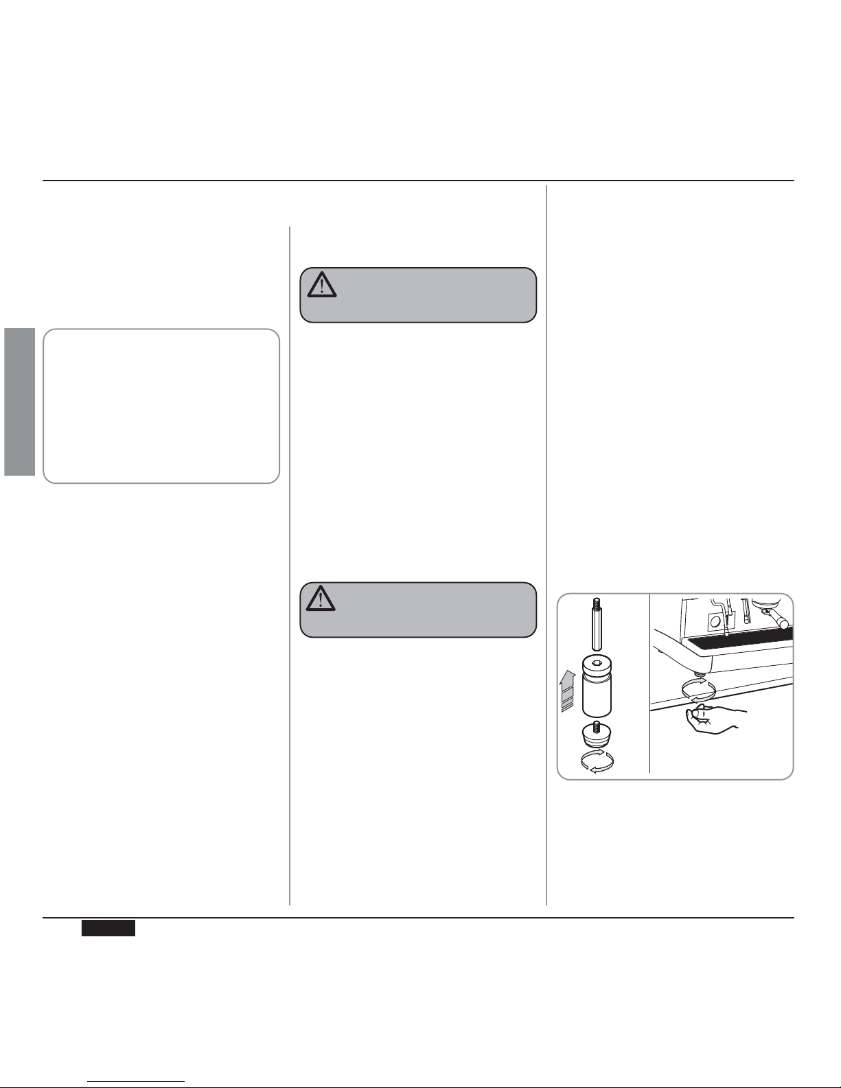
After unpacking, assess that the machine and
its accessories unit are complete, then proceed
as follows:
• place the machine so that it is level on a flat
surface;
• assemble its supporting feet by inserting
the insert into the cylindrical unit;
• twist the rubber foot into the screw thread
inside the unit;
• screw the whole assembled unit into the
allotted setting for the machine’s adjustable
feet;
• level the machine by regulating the adjustable feet;
NOTE: the unit grooves have to face upwards,
as shown in the following illustration.
It is advisable to install a softener (1) and then
a mesh filter (2) on the external part of the
plumbing system, during preliminaries and after
levelling the machine.
In this way impurities like sand, particles of calcium, rust etc will not damage the delicate graphite surfaces and durability will be guaranteed.
Fig. 9
4.
INSTALLATION
AND PRELIMI-
NARY OPERATIONS
44
ENGLISH
Always quote the machine serial number in all
communications to the manufacturer, Nuova
Simonelli.
The machine is transported on pallets which
also contain other machines - all boxed and
secured to the pallet with supports.
Prior to carrying out any transport or handling
operation, the operator must:
• put on work gloves and protective footwear,
as well as a set of overalls which must be
elasticated at the wrists and ankles.
The pallet must be transported using a suitable means for lifting (e.g., forklift).
CAUTION
RISK OF IMPACT OR CRASHING
CAUTION
RISK OF IMPACT OR CRASHING
During all handling operations, the operator
must ensure that there are no persons,
objects or property in the handling area.
The pallet must be slowly raised to a height
of 30 cm (11,8 in) and moved to the loading
area. After first ensuring that there are no
persons, objects or property, loading operations can be carried out.
Upon arrival at the destination and after
ensuring that there are no persons, objects
or property in the unloading area, the proper lifting equipment (e.g. forklift) should be
used to lower the pallet to the ground and
then to move it (at approx. 30 cm (11,8 in)
from ground level), to the storage area.
Before carrying out the following operation,
the load must be checked to ensure that it is
in the correct position and that, when the
supports are cut, it will not fall.
The operator, who must first put on work
gloves and protective footwear, will proceed to cut the supports and to storing the
product. To carry out this operation, the
technical characteristics of the product
must be consulted in order to know the
weight of the machine and to store it accordingly.
3.
TRANSPORT AND HANDLING
3.1
MACHINE
IDENTIFICATION
3.2
TRANSPORT
3.3
HANDLING
Fig. 8

45
ENGLISH
Fig. 10
NOTE: For a correct functioning of the machi-
ne the water works pressure must not
exceed 4 bars.
Otherwise install a pressure reducer
upstream of the softener; the internal
diameter of water entrance tube must
not be less than 6mm (
³⁄₈
”).
KEY
1 Softener
2 Mesh filter
3 Drain Ø 50 mm
CAUTION
RISK OF SHORT CIRCUITS
Prior to connecting the machine to the electrical
mains, assess that the voltage shown on the
machine’s data plate corresponds with that of
the mains.
If it does not, carry out the connections on the
basis of the available electrical line, as follows:
•for V 380 / 3 phases voltage +Neutral:
Fig. 11
Fig. 12
KEY
1 Black
2 Grey
3 Brown
The machine must always be protected by
an automatic omnipolar switch of suitable
power with contact openings of equal distance or more than 3mm.
Nuova Simonelli is not liable for any damage to people or objects due to not observing
current security measures.
Avoid throttling in the connecting tubes.
Assess that the drain pipe (3) is able to eliminate waste.
WARNING
2
3
1
•for V 230 / monophase voltage
4 Blue
5 Yellow-green
Recommended mains pressure for the
water is [2.3] bar.
IMPORTANT
Following these operations, connect the plumbing systems as illustrated in the following figure.
NOTE: At the start of the day’s activities and in
any case, if there are any pauses of
more than 8 hours, then it is necessary
to change 100% of the water in the circuits, using the relevant dispensers.
NOTE: In case of use where service is conti-
nuous, make the above changes at
least once a week.

46
ENGLISH
Fig. 17
Fig. 16
Fig. 15
5.
ADJUSTMENTS TO BE MADE BY A QUALIFIED TECHNICIAN ONLY
NOTE: this operation must be carried out with
the machine turned off.
All models are equipped with a
level gauge to keep the water level inside the
boiler constant.
When using the machine for the first time, it is
advisable to fill the boiler by hand to avoid
damaging the electrical resistor and turning on
the electronic protection.
If this should happen, just turn the machine off
and then start it up again to complete its loading procedure (see chapter “MACHINE
FUNCTIONS MESSAGE – LEVEL ERROR”).
To fill the boiler manually for the first time, proceed as follows:
• remove the worktop grid;
• turn the manual “A” level tap so that water
will enter the boiler;
• once the maximum level has been reached,
as indicated by the optical level, turn tap “A”
off;
• switch the machine on by placing the gene
ral switch on “I”; this will activate the level
gauge which will automatically maintain the
water level inside the boiler.
NOTE: this operation can be carried out while
the machine is turned on.
To adjust the service pressure of the boiler,
thus regulating the water temperature, according to the various functions and needs of the
coffee desired, proceed as follows:
• remove the worktop grid cover;
• remove the protective metal sheet by
unscrewing the two side screws (A) as
shown in the following illustration;
5.1
FILLING BOILER
MANUALLY
5.2
PRESSOSTAT/PUMP
ADJUSTMENT
• turn the pump registration screw, turning it
clockwise to INCREASE and counter clock
wise to DECREASE the pressure.
• The set pump pressure is shown on the
lower part of the gauge.
Once the adjustment operation has been completed, screw the protective metal sheet back
into its setting and replace the worktop grid
cover.
• turn the pump registration screw, turning it
clockwise to INCREASE and counter clock
wise to DECREASE the pressure.
Advisable pressure: 1 - 1,4 bar
(according to the kind of coffee).
Advisable pressure: 9 bar.
Fig. 13
A
MAX
MIN
MAX
MIN
Fig. 14
A

47
ENGLISH
NOTE: this operation can be carried out while
the machine is turned on.
All models are equipped with a hot
water mixer tap which adjusts the water temperature and optimises the system’s performance.
To adjust the hot water economiser, turn the
registration knob as follows:
• unscrew the panel (A) situated below the
steam and hot water levers;
• remove the panel;
• turn the registration knob.
Fig. 18
Fig. 19
5.3
HOT WATER ECONOMISER ADJUSTMENT
CLOCKWISE/COUNTER CLOCKWISE to
INCREASE/DECREASE the hot water temperature;
5.4
5.4 CLOCK BATTERY
REPLACEMENT
(only for the Vip Plus
version)
The Vip Plus electronic control unit is equipped
with a lithium battery to provide the clock with
an approximately three-year autonomy period,
after which replacing the battery may prove
necessary.
In case the machine has remained unutilised
for a long time, the clock can be blocked by proceeding as follows:
• with the machine off the display will read:
• press the key for 5 seconds; the
display will read:
The clock will start up again as soon as the
machine is plugged in once more.
5.5
PUSH-BUTTON PANEL
REPLACEMENT
Replacement of the lithium battery must be
carried out EXCLUSIVELY by Qualified
Technician.
Nuova Simonelli cannot be held liable for
any damage to people or things due to non
observance of the safety prescriptions
described in this booklet.
For correct functioning of the machine, personalising each button panel card at time of
replacement is necessary; proceed as follows
on the selectors placed on the card (on the key
side).
WARNING
5.6
ELECTRONIC DISPLAYS
Each model can come with the optional electronic displays which can be set by using the
dating key. To set, follow the instructions provided in this booklet.
• when the operation has been completed,
screw the protective panel back on.
OFF
STOP CLOCK
A
GROUP sw1 sw1 sw1 sw1 sw1 sw1 sw1 sw1
Group 1 On Off Off Off On Off Off Off
Group 2 Off On Off Off Off On Off Off
Group 3 Off Off On Off Off Off On Off
Group 4 Off Off Off On Off Off Off On

48
ENGLISH
Before starting to use the appliance, the operator must be sure to have read and understood
the safety prescriptions contained in this booklet.
The Aurelia Vip Plus model is provided with
an optional key management system of waiter keys and technician U key, so that different keys correspond to different functions.
The waiter keys can access the normal working functions and can be displayed but not
modified on the program menu (Ch.7). The
technician U key allows you to access all
the functions and to modify the parameters
of the programming menu.
6.1
TURNING THE
MACHINE ON
Fig. 20
Fig. 21
6.1.1 AURELIA VIP PLUS
• Plug the machine in and position the main
switch on “I”.
• The state of the machine will be shown by
the signal:
• The unlit display will read:
NOTE: The machine is not operative in that the
main switch only supplies the electronic
card.
For electronic card maintenance, turn the
machine off by means of the external main
switch or disconnect the plug.
WARNING
MANUAL SWITCHING ON/OFF
Automatic On/Off NOT PROGRAMMED
NOTE: make sure that the general switch is
always on the position “I”.
The state of the machine will be shown
by the signal:
OFF
6.
USE
SWITCH ON: press the key for 2
seconds, the buzzer will beep,
the display will light up to indicate the release of the
EPROM for about 1 second.
The control unit will start up an
auto diagnosis cycle to check
the functions, all the selection
keys will light up.Once the
check is completed the display
will read:
with the day and time. When
110°C has been reached, the
heating message will disappear and will be replaced by
the words:
NOTE: on completion of the check up all the
selection keys are activated.
POWER OFF: press the key for
2 seconds; the machine will turn off and
the display will read:
In case the auto diagnosis indicates error or
malfunction, call an assistance centre; the
operator MUST NOT intervene.
WARNING
HEATING
MACHINE READY
OFF

49
ENGLISH
Automatic On/Off PROGRAMMED
NOTE: make sure that the general switch is
always on the position “I”.
The state of the machine will be shown
by the signal:
The machine will SWITCH ON at the first
programmed switch-on time (see the section entitled PROGRAMMING at the paragraph PROGRAMMING ON - OFF).
The control unit will perform an
auto diagnosis of all functions
and all of the selection keys
will light up.
Once the diagnosis is complete, the display will read as follows:
with the date and time. Once
the temperature of 110°C has
been the word “Heating” will
disappear to be replaced by:
NOTE: once the auto diagnosis has been com-
pleted all the keys are activated.
6.1.2 AURELIA V/ESSE
SWITCHING ON: plug the machine in and
position the main switch on “I”
The state of the machine will
be shown by the signal:
In case the auto diagnosis indicates error or
malfunction, call the assistance centre; the
operator MUST NOT intervene.
In case the auto diagnosis indicates error or
malfunction, call the assistance centre; the
operator MUST NOT intervene.
The machine will SWITCH OFF at the first
time set for stopping the coffee maker (see
chapter on PROGRAMMING and paragraph
on PROGRAMMING ON – OFF).
NOTE: the machine can be switched on or off
manually as indicated in the previous
paragraph.
Fig. 22
SWITCHING OFF: press the main switch into
the “O” position to switch the
machine and the signal off.
6.1.3 AURELIA VIP-V/ESSE WITH
ELECTRONIC DISPLAYS
(OPTIONAL)
SWITCHING ON: Plug the machine in and
position the “A” switch on “I”;
the machine will turn on. By
pressing the “B” switch onto
position “I” an illuminated display will turn on even when the
machine is switched off.
WARNING
WARNING
Fig. 23
In case the auto diagnosis indicates error or
malfunction, call the assistance centre; the
operator MUST NOT intervene.
WARNING
HEATING
MACHINE READY

50
ENGLISH
CAUTION
RISK OF BURNS OR SCALDING
6.2
SELECTION
CONFIGURATION
Set the desired function on the available keys
placed above the filter-holders (see chapter
“DESCRIPTION”).
Fig. 24
BUTTONS KEY
(Selection configuration)
1 small coffee
2 small coffees
1 long coffee
2 long coffees
Continuous
6.3
MAKING COFFEE
Unhitch the filter-holder and fill it with one or
two doses of ground coffee depending on the
filter used.
Fig. 25
Press the coffee with the provided coffee presser, dust off any coffee residue from the rim of
the filter (this way the rubber gasket will last
longer).
Insert the filter in its unit.
Press the desired coffee button:
By starting up the coffee brewing procedure the
unit’s pump is activated and the unit’s solenoid
valve is opened.
By pressing it, the button will turn on and signal
the operation
NOTE: when in pause, leave the filter-holder
inserted in the unit so that it will keep
warm. To guarantee the utmost thermic
stability during use, the delivery units
are thermo-compensated with complete hot water circulation.
6.4
USING STEAM
Fig. 26
While using the steam nozzle, you must pay
attention to not place your hands beneath it
or touch just after it has been used.
1 small coffee
2 small coffees
1 long coffee
2 long coffees
To use steam just pull or push the provided
lever (Fig. 26).
By pulling it completely the lever will hold a
position of maximum delivery; by pushing it, the
lever will automatically give way.
The two steam nozzles are articulated to guarantee their easy use.
NOTE: Before using the steam wand, always
bleed out any condensation for at least
2 seconds or according to the manufacturer’s instructions.

51
ENGLISH
It provides steam ejection to foam milk or to
heat up other liquids.
Place a suitable container (see Fig. 1 position
16) under the automatic steam nozzle.
Press the steam selection button once .
Make sure that the button lights up.
Steam will be ejected from the automatic steam
nozzle.
Press it again to arrest delivery.
The Plus and V models provide an optional
nozzle with a temperature probe which remains
on until the beverage being heated reaches the
set temperature.
6.5
MAKING CAPPUCCINO
To obtain the typical cappuccino foam, immerse the nozzle all the way into a container 1/3
full of milk (preferably cone-shaped). Turn on
the steam. Before the milk starts to boil, pull the
nozzle slightly up and lightly move it vertically
across the surface of the milk. When you have
completed the procedure, clean the nozzle
carefully with a soft cloth.
Fig. 27
6.6
HOT WATER
SELECTION
CAUTION
RISK OF BURNS OR SCALDING
While using the hot water nozzle, pay careful attention not to place your hands
beneath it or touch it just after it has been
used.
This nozzle delivers hot water to make tea or
herb teas.
Place a suitable container under the hot water
nozzle (see Fig. 1, position 21).
Press the hot water selection button once .
Make sure the button lights up.
Water will be delivered from the hot water nozzle for as long as the set time indicates.
NOTE: Hot water can be delivered at the same
time as coffee.
6.7
TIMED STEAM NOZZLE
CAUTION
RISK OF BURNS OR SCALDING
While steam is being delivered do not touch
the nozzle with any part of the body, and
have it always facing downwards towards
the cup-holder grid.

52
ENGLISH
AUTO.CLEAN.CYCLE
DOSE PROGRAM.
DELIVERY COUNT
ON-OFF PROGRAM.
CUP-WARMER PRO.
DATE/TIME
GRINDING
HISTORICAL ALARM
MAINTENANCE
LANGUAGE
TEMPERATURE
LIGHT ADJUST
AUTOMATIC CLEANING CYCLE
(function also available with T visualization key)
• Press the key to access program;
the display will read:
• Press and the display will read:
• The central key in each unit will begin
to flash on and off. Insert the blind filter (fig
2 A07) into the filter-holder, add half a dose
of PULICAFF and attach the filter-holder
into the unit where you intend to carry out
the automatic cleaning cycle. Carrying out a
cleaning cycle in more than one unit at a
time is possible.
• Press the key to start the unit
automatic cleaning cycle. The display
will read:
where 1L indicates that the cleaning cycle
has been activated within the 1st unit. Once
the cycle of 15 deliveries of 5 seconds each,
with a 10-second pause between each delivery, has been completed the selected unit
key will begin to flash on and off again
and the display will read.
RINSE
AUTO.CLEAN.CYCLE
AUTO.CLEAN.CYCLE
SELECT
RESET key to turn the machine on
and off and to exit menu.
7.
PROGRAMMING
7.1
KEY
Technician/waiter key lock.
CURSOR key: to scroll
the menu and to increase
and decrease values.
ENTER key: to access the menu.
LIST OF PROGRAMMABLE FUNCTIONS
Operation to be carried out EXCLUSIVELY by a Qualified Technician.
Adjustment by NON qualified technicians can invalidate the guarantee.
7.2
PROGRAMMING
AURELIA VIP PLUS
To access the programming units, proceed as
follows:
NOTE: the procedure can be carried out with
the machine on.
• Insert the key marked U (see chapter
“USE”) in the provided keyhole.
Fig. 28
2
1
3
4
5
6
1
LCD Display.
2
3
4
6
5
AUTO.CLEAN.CYCLE
1L

53
ENGLISH
probe and the display will read:
followed by the temperature set previously
by the manufacturer.
Press the keys to vary the
temperature of the beverage you want to
heat. When the desired temperature has
been reached, the steam delivery will automatically stop.
• In the standard version (without temperature probe), on pressing the the display will read:
followed by the amount already set by the
manufacturers.
Press the keys to vary the
steam delivery time.
• If a new sampling is desired press the
button again.
Delivery starts. When the desired dose has
been reached press the button again .
• The display will show the new value set
which can still be changed by pressing the
.
• Press the key or go on to a further
selection to terminate the operation.
The button will turn off.
PROGRAMMING DOSES
• Press the key to access the programming; the display will read:
• Press and the display will read:
All the programmable keys will start to flash
on and off.
• Press the coffee key you wish to program;
the display will read:
Followed by the dose amount already set by
the manufacturers.
• Vary the dose, by pressing the buttons
.
• By pressing the coffee key you want to program, delivery will be started up (in the
meantime all the other keys will turn off).
• Select the dose of delivered coffee and then
press the coffee key you want to program
again.
• Eliminate any residues of PULICAFF from
the blind filter and press the rinsing
cycle starting up key of the unit or units
where the cleaning cycle has been effected.
The letter R will remain on the display like
the key . Once the rinsing cycle of the
selected unit or units has been completed,
the display will read.
MACHINE READY
VOLUME C.C:
PROGRAM. DOSES
PROGRAM. DOSES
SELECT
HOT WATER
• Press the button and make sure that
it lights up.
The display will read:
followed by the value already set by the
manufacturers.
Press the keys to vary the
hot water delivery time.
• If a new sampling is desired press the
button again.
Delivery starts. When the desired dose has
been reached press the button again .
• The display will show the new dose value
set which can still be changed by pressing
the keys.
• Press the key or go on to a further
selection to terminate the operation.
The button will turn off.
TIMED STEAM
• Press the button and make sure it
lights up.
In those models provided with a temperature probe (optional) the control unit automatically recognizes the presence of the
SECONDS
STEAM SECONDS
STEAM. TEMP. °C
• The display will show the new dose amount
which can still be changed by means of the
keys .
• Going on to another selection or pressing
the key.
The set coffee key will turn off.

54
ENGLISH
TANDARD DOSES
• When the display reads:
we mean to recall the standard dose values.
• Press the key.
The display will read:
Once again the delivery buttons will begin to
flash (see. Fig. 29) on and off.
• Select one or more continue keys (the key
or keys selected will remain lit up).
The key or keys will recall the selected unit’s standard doses.
• Press the key to confirm.
The display will read:
NOTE: all the selections can be programmed
for a maximum of two minutes; after
that time a flashing message will
appear on the display saying:
DELIVERY COUNT
• The display will read:
• Press the key to confirm.
At this point the display will read:
• Press the or the key to
exit without confirmation.
TRANSFERRING DOSES
• When the display reads:
transferring the set dose to other units is
possible by pressing the key.
The display will read:
at this point all the delivery buttons belonging to each individual unit will flash as illustrated in Fig. 31.
• By selecting the continue key once on
the first unit ( the key will stop flashing but
remain lit up), the set values will be transferred from the first unit to the other units.
Fig. 29
PROGRAM DOSES
SELECT
DOSES TRANSFER
SELECT GROUPS
DOSES TRANSFER
SELECT GROUPS
DEFAULT SETING
SELECT GROUPS
PROGRAM DOSES
SELECT
• By pressing the key the display will
read:
• All the delivery keys will start to flash on and
off. By pressing one of the delivery keys the
amount of the deliveries made will be visualised.
• To set the counter back to zero, press the
key.
NOTE: The continuous coffee equals one deli-
very.
• Press to access waiter counts (if
provided).
• Press the key and the display will
read:
All the units’ small coffee keys will begin
to flash on and off.
Example:
By selecting one of the first unit’s keys (the
selected key will remain lit up) the display
will read:
which means the total amount of deliveries
for that unit.
• To set the counter back to zero press
.
• To access the waiter counter press .
• When the display reads:
press and the display will read:
PROGRAM DOSES
SELECT
ERROR
DELIVERY COUNT
SELECTION TOTAL
GROUP TOTAL
GROUP TOTAL
GR. 1 DELI.
GROUP TOTAL

55
ENGLISH
• Press to confirm and to set the
cup-warmer at OFF, which includes from 0
to 60 minutes.
NOTE: By programming one of the two
ON/OFF values at 0, will automatically
exclude the function.
When the cup-warmer has been set, the
button will start to slowly flash.
• Press the key to go on to the next
page.
DATE/TIME PROGRAMMING
• The display will read:
• By pressing the key, the display will
read for example:
The times will start to flash on and off.
• Vary the hours and the minutes by using
the keys .
• Confirm by pressing the key.
Once the hours and the minutes have been
varied press again and vary the day,
the month and the year by using the same
procedure as described above.
On completion press to go on to the
next page.
This indicates the total amount of deliveries
made.
• To set the counter back to zero press .
• To access total counts per waiter press
.
• By pressing the key the display
will read:
To access the automatic cleaning counter
press .
• The keys will flash on and off; by pres-
sing the unit key the number of cleaning
cycles effected will appear. By pressing the
key (reset) for 5 seconds the counter will be
set back to zero.
ON/OFF PROGRAM.
• The display reads:
• By pressing the key, the display will
read:
where the ON and OFF values indicate
when the machine will turn on and off.
• Press to change the day
forward and backward.
• Press to vary the programmed star-
ting up time (the message ON 07:30 will
start to flash on and off).
• Use the keys to vary the
starting up time.
• Press to confirm and to go on to
the programmed switching off time (the
message OFF 23.30 will start to flash on
and off).
• Use the keys to vary the
switching off time.
• Confirm by pressing .
• To de-activate the on/off function on weekly
day-off, press .
The display will read:
(to reinstate, press )
After the word SUNDAY, by pressing
again, a beep will signal that
you have come to the following page.
CUP-WARMER PROGRAMMING
• The display will read:
• By pressing the key, the display will
read (for example):
The words ON05 will begin to flash on and
off; use the keys to vary
the opened cup-warming time (anywhere
between 0 and 60 minutes.
DAY OFF
MACHINE TOTAL
ON-OFF PROGRAM
MONDAY
ON 07:30 OFF 23.30
CLEANING COUNTER
CUPWARMER PROG.
ON05 OFF60
DATE/HOUR
MONDAY 08:22
08- MAG-03

56
ENGLISH
GRINDING CONTROL PROGRAMMING
The Aurelia Plus is equipped with an electronic system to control delivery times
according to the coffee grinding fineness.
• The display will read:
• By pressing the key on the line
above, it will read:
and in the line below, the current setting
• Use the keys to change
the setting; use the key to quit the
function without confirming, or press the key
to confirm.
• If the delivery time display reads:
• then the sub-page for grinding control
values is skipped, to pass directly to the following page:
If the delivery time display is on when a deli-
GRINDING
very is started - unless with the Continuous
function - the bottom line of the display will
show the delivery time (or times if more than
one unit is delivering).
Each group has an area of the bottom line:
the area on the left is for unit 1; the area
alongside it is for unit 2 and so on, until the
area on the far right, which is for unit 4.
The different areas are separated by vertical
bars; if a group is not delivering, the area is
empty.
Here below is an example: unit 1 is delivering (it has just started and 0 seconds have
passed); unit 2 has been delivering for 12
seconds and unit 4 is delivering (it has been
delivering for 21 seconds).
If the time is confirmed:
the machine passes to the grinding control
value settings.
• By pressing the key the display will
read as follows:
where 00-40 indicates the maximum time (in
seconds) allotted for the delivery of a sample amount of coffee, equal to 10cc for a single coffee and 30cc for a double coffee.
The first value will begin to flash on and off;
modify by using the keys.
To confirm press the key.
• Press the key again to go on to the
next value.
To modify the previous value, proceed as
described above.
NOTE: If the system detects a delivery time (of
the sampled amount) inferior to the programmed minimum, the display will
read:
(See chapter called “MACHINE FUNCTION MESSAGES”) which means you
have to adjust the coffee grinder to
reduce the grain.
If the system detects a delivery time
(of the sampled amount) superior to the
programmed maximum, the display will
read:
DELIVERY TIME
DELIVERY TIME
SET
DELIVERY TIME
NOT SET
DELIVERY TIME
SET
FAULTS HISTORY
THURSDAY 12:00
0 I 12 I I 21
Area reserved to the
delivery time of unit 1
Area reserved to the
delivery time of unit 4
Area reserved to the
delivery time of unit 2
Area reserved to the
delivery time of unit 3
DELIVERY TIME
NOT SET
1 ESPRESSO 00-40
2ESPRESSO 00-40
COARSE GRINDING
FINE GRINDING

57
ENGLISH
• Use the keys to set both
values.
• Use the key to confirm.
Once the set delivery limit or the set maintenance date have been reached, the display will visualize the message:
Insert the “U” key (see chapter “USE”) and
set the display back to zero by pressing the
key.
To go on to the next page, press the
key.
SELECTING THE DESIRED LANGUAGE
• The display will read:
• Press the key to visualise the language already set. Choose the desired language by using the keys.
• To confirm press .
TEMPERATURE UNITY MEASURE
SELECTION
• The display reads:
• By pressing , the display will read
(See chapter called “MACHINE FUNCTION MESSAGES”) which means you
have to adjust the coffee grinder to
increase the grain. By setting the
values at 00-40, the function is excluded.
• On completion press to go on to the
next page
HISTORICAL ALARM VISUALISATION
• The display will read:
• By pressing the key, the display will
read:
• Pressing the key, allows you to
scroll down the ten previous alarms saved in
the memory. After the tenth alarm, by pressing the key again you can go on
to the next page.
MAINTENANCE PROGRAMMING
• The display will read:
• By pressing the key, the display will
read:
FAULTS HISTORY
ERROR 01
MAINTENANCE
MAINTENANCE
LANGUAGE
DELIVE. 10000
01 GENNUARY 2005
O
• Press to modify the measures unit setted
.
• Press to confirm.
KEYBOARD LIGHTING ADJUSTMENT
• The display reads:
• By pressing , key, the display will
read:
• With the
K
KEYS
light Xblinking,. Select the
value of desired brightness choosing from a
minimum value of 1 to a maximum of 6 by
using the keys.
• Confirm by pressing .
• The temperature
DISPLAY
value Yblinks
and with keys it is
possible to set the display lighting
Y
from a
minimum value of 1 to a maximum of 3.
• Confirm by pressing .
• The display will visualize the message:
TEMPERATURE
CELSIUS
FAHRENEIT
LIGHT ADJUSTMENT
KEYS X
DISPLAY Y
LIGHT ADJUSTMENT

58
ENGLISH
7.3
PROGRAMMING
AURELIA V
DOSE PROGRAMMING
To access the programming units, proceed as
follows:
NOTE: the procedure can be carried out with
the machine on.
• To access the dose programming state of
each unit press the first unit’s continuous
delivery key for 5 seconds.
• The delivery keys will begin to flash on and
off.
• Access into the first unit’s programming
allows you to set the machine’s function
parameters.
COFFEE DOSE PROGRAMMING
To program the relative water doses for one of
the delivery keys, proceed as follows:
• fill the filter-holder with the correct dose of
coffee (the filter-holder can be single or double depending on the key you wish to program).
• Insert the filter-holder into the unit.
• Press one of the delivery buttons (see illustration):
The delivery will start; once the desired
amount has been reached, press the continuous key.
• The delivery will stop and the chosen dose
key will turn off (the other keys will continue
to flash).
• Press the continuous key to exit programming or to continue programming other
dose keys.
NOTE: This procedure is usable on all the
machine units except if carried out one
at a time; the other groups can carry on
normally.
HOT WATER PROGRAMMING
• Access the programming according to the
relative procedure.
• Press the hot water selection key
.
• Hot water delivery will start.
• Establish the desired hot water dose and
press the key again . .
• Press the continuous key to exit the
programming or to continue programming
other selection keys.
Technician: To enable the pump while hot
water is being dispensed, enter the programming mode for the first dispensing
group then press the continual button
for the second group.
• To change the settings, it is sufficient to
press the hot water button : if the
button is not lit, the pump will not be enabled
while hot water is being dispensed; if the
button is lit while hot water is dispensed, the
pump will be activated.
• Press the continual button for the
second dispensing group to confirm the setting.
AUTOMATIC CUP-WARMER PROGRAMMING
• Access the programming according to the
relative procedure.
• Press the cup-warming selection key
.
• The delivery keys of the first and second
unit will respectively signal the allotted automatic switching on and off times while the
continuous keys of the first and second
units will flash on and off.
As described in the chart, each delivery key
has an associated value, the starting up
time of the cup-warmer is given by adding
up the values of the first unit’s lit-up keys.
The same counting method is used for the
cup-warmer switching off time with the keys
of the second unit.
TIMED STEAM PROGRAMMING
• Access the programming according to the
relative procedure.
• Press the steam selection key .
• Steam ejection will start.
• Establish the desired dose of steam and
press the key again .
• Press the continuous key to exit the
programming or to continue programming
other selection keys.
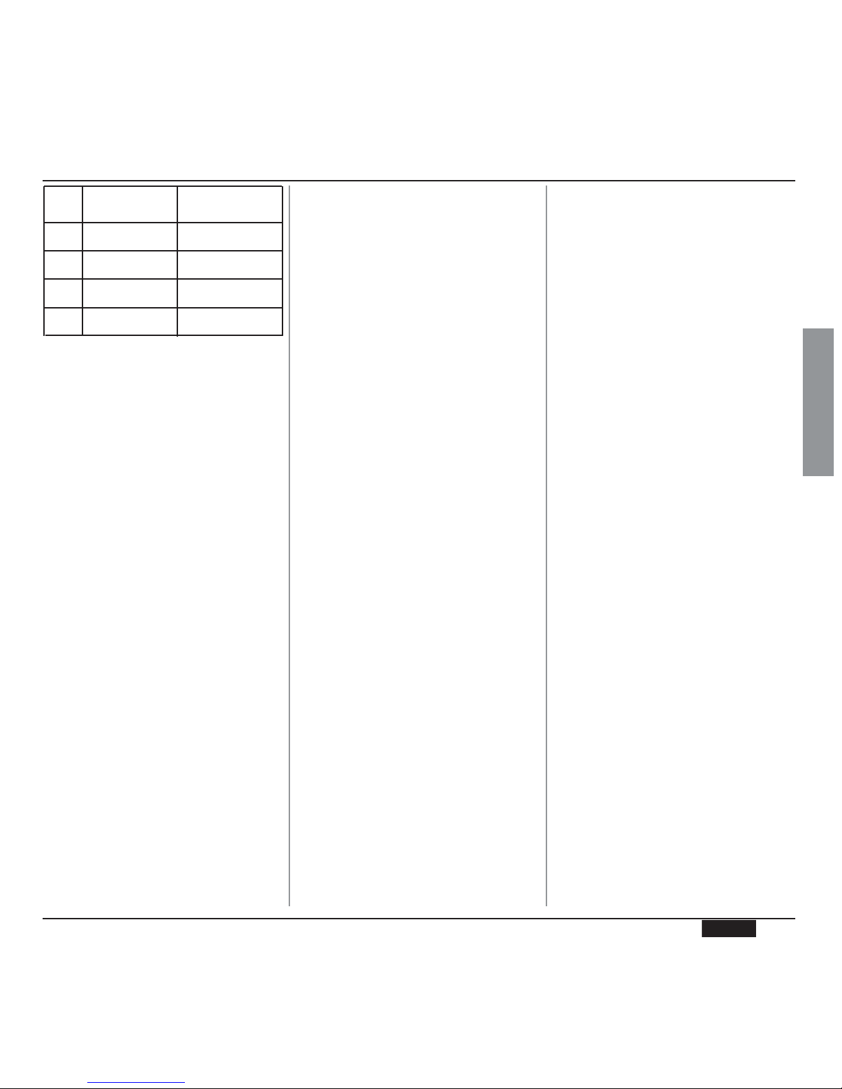
59
ENGLISH
STEAM NOZZLE WITH TEMPERATURE PROBE (OPTIONAL)
• Make sure the temperature probe is connected to the control unit.
• The temperature value can be planned by
sampling or manually depending by the
types of memorization planned in the parameter setting section and value goes from a
minimum of 50°C to a maximum of 95°C.
• By pressing the key of the second
group is possible to chose if you wont set
the steam temperature value manually or by
sampling.
• When you enter in this part of the menu, the
key of the second group is switched
on.
• By pressing the key of the second
group , it is possible to change the way in
which settings are stored to memory.
• Press the continuous delivery key for
the 2nd unit to memorise the temperature
value input mode.
Sampling:
• After entering in the program of the first
group, put a jag with milk under the steam
wand and press the key, the delivery of steam will start.
• By pressing again the key, or if it is
reached the maximum temperature, the control
board memorizes the temperature reached.
LEVELLING PUMP ACTIVATION
• Access the programming of the first group
according to the relative procedure.
• Press the second unit continuous
key (the key will light up).
• Press the second unit 1 small coffee
key.
NOTA: If the I small coffee key is lit up,
the pump will start up during the level.
If the 1 small coffee key is not lit
up, the pump will not start up during the
level.
• Press the second unit continuous
key.
In this way the selected pump setting is stored.
• To exit the programming, press the first unit
continuous key.
NOTE: The settings will be saved even when
exiting the first unit programming
directly.
ADJUSTING KEYBOARD LIGHTING
INTENSITY
• Access the programming of the first group
according to the relative procedure.
• Press the second unit continuous
delivery key.
• The second unit 2 long coffees delivery key will flash on and off.
• Press the key more than once to vary the
light intensity.
NOTE: You can set a maximum of five different
degrees of light intensity.
• To store the set light intensity values in the
memory, press the second unit continuous
delivery key.
• To exit the programming, press the first unit
continuous delivery key .
NOTE: The settings will be saved even when
exiting the first unit programming
directly.
Keys
1° GROUP
(time ON)
2° GROUP
(time OFF)
2 minutes
4 minutes
5 minutes
10 minutes
8 minutes 20 minutes
16 minutes 40 minutes

60
ENGLISH
Manually:
• After entering in the program of the first
group, press the keys of the first
group, keys of the first and second group
show the temperature starting from a minimum value of 50°C.
• At every key has an value:
• Sum together the value associated to the
relevant lit key to a minimum value of 50°C
to obtain the temperature setting.
• If the key is lit, it is necessary to add the
reference value, while it is not required if the
key is not lit.
• By pressing again the key the value
is planned and the machine came back to
the general programming.
This way of setting doesn't use the delivery
of steam.
• To escape from the program and save the
setting, press the continuos key of
the first group.
Technician:
• In this steam temperature setting is possible
to plan the offset value, from -15°C to
+15°C, to obtain the correct temperature
value.
• By pressing the key of the first group,
is showed the offset value setted:
the way to show is the same of the way to
show the final steam temperature.
• The keys of the first group show a value
from 0 to 15°C,the key of the
second group show the offset sign:
• it is switched on the value is POSITIVE, if
the key is switched off is NEGATIVE.
• By releasing the key of the first group,
you memorize the value and came back to
the steam temperature setting.
Keys
1° GROUP
2° GROUP
1 °C
2 °C
10 °C
20 °C
4 °C -
8 °C -
Keys
1° GROUP
2° GROUP
1 °C
2 °C
+ o - °C
-
4 °C -
8 °C -
STANDARD DOSE PROGRAMMING
• Setting predetermined values for the four
doses of the first delivery unit is not possible. To do so, you must:
• Press the first unit continuous delivery
key and keep pressing it for at least 8
seconds, until the flashing delivery keys of
the first unit turn off.
• The standard doses are illustrated in the following table:
NOTE: A time of 0 seconds for water and
steam give way to their continuous
functioning.
DOSE COPYING
This procedure must be carried out for each
unit individually by pressing the c on ti nuous delivery key of the unit you desire to
copy the doses onto and keep pressing it for at
least 8 seconds, until the flashing delivery keys
turn off
40 cc
60 cc 50 cc 85 cc 9 sec.
0 sec.

61
ENGLISH
ADJUSTING LIGHTING INTENSITY
KEYBOARD
• Access programming according to the relative procedure.
• Adjust the light intensity of the keys by pressing the first unit’s 1 long coffee key
more than once.
NOTE: To exit programming press the
key.
ACTIVATING LEVELLING PUMP
• Access programming according to the relative procedure.
• Press and keep pressing the 1 long coffee
key belonging to the second unit.
• To set the activation of the pump during
levelling, once the programming state has
been activated, keep the second unit
key pressed.
The second unit key will light up and
by means of the first unit key the
pump setting will be visualized: if it is lit up
the pump will function during levelling; if it is
not lit up the pump will not be activated
during levelling.
By pressing the first unit key the pump
setting during levelling can be modified.
NOTE: to exit the programming press the
key.
DOSE PROGRAMMING
In the Aurelia Esse version only the doses of
water and timed steam can be programmed.
To access the programming state you must:
• press the cup-warming key for five
seconds.
• The selection keys and the 1 long coffee key
belonging to the first unit will start to
flash on and off while the other delivery keys
of the other units will turn off.
HOT WATER
• Once the programming state has been
accessed, by pressing the key,
hot water delivery will be activated; once the
desired dose has been reached press the
key again and the set delivery time
will be stored in the control unit.
TIMED STEAM
• Once the programming state has been
accessed, by pressing the key,
hot water delivery will be activated; once the
desired dose has been reached press the
key again and the set delivery time
will be stored in the control unit.
7.4
PROGRAMMING
AURELIA ESSE
AUTOMATIC CLEANING CYCLE
• To enter in the automatic cleaning cycle, you
must switch off the machine and switch on
the machine holding pressing the
hot water and cupwarmer keys
during the initial Lamp-test. At the end of the
Lamp-test, starts to blinking the
and keys and the ( o n e
long coffee) keys of each groups.
• By pressing the key starts the cleaning
cycle in the group selected. When the cleaning cycle is finished, is possible to begin
the rinsing cycle in the same group, by pressing again the key.
• If you want make the rinsing cycle in an
other time it's enough to switch off the
machine: the control board memorizes the
cleaning cycles that you must end. With the
next turn on, the control board will enter
automatically in the cleaning cycle, without
pressing the and keys.
• By pressing the and keys
for 2 seconds you escape from the cleaning
cycle in case there are not cycles to end,
otherwise the keys of the group, in that
you must finish the rinsing cycle, remain
with blinking.
• By holding pressing the and
keys for other 2 seconds you force the escape from the cleaning cycle by resetting the
rinsing cycle.
• If the cleaning and the rinsing cycle is
ended, the key of the group switch
off; if there are no cycles to finish, the
machine return ready.

62
ENGLISH
To switch the machine off press the main switch
and set the machine to the O energy position.
The machine must be set to “O” power (switch
off and disconnector open) before any cleaning
operations are performed.
Do not use solvents, chlorine-based products or abrasives.
Cleaning the work area: remove the worktop,
lifting it up from the front and sliding it out.
Remove the water collection dish underneath
and clean everything with hot water and cleansers.
Cleaning the bottom: To clean all the chromium-plated areas, use a soft, damp cloth.
8.1
SWITCHING OFF THE
MACHINE
8.2
CLEANING THE OUTSIDE
OF THE MACHINE
8.3
CLEANING THE STAINLESS COFFEE-HOLDERS
Fig. 30
The stainless coffee-holders are situated under
the delivery units, as shown in figure (31).
Fig. 31
NOTE: To clean proceed as follows:
• Turn the screw placed in the centre of
the coffee-holder.
• Slide the coffee-holder out and check
that its holes are not obstructed but
clean.
• If obstructed, clean as described
(Paragraph “CLEANING FILTERS
AND FILTER-HOLDERS”)
We recommend cleaning the coffeeholder once a week.
Aurelia Version
V/ESSE
Aurelia Version
Vip/V/ESSE
WARNING
8.
CLEANING AND MAINTENANCE
CAUTION
RISK OF INTOXICATION
8.4
CLEANING THE UNIT
WITH THE AID OF THE
BLIND FILTER
The machine is pre-set for cleaning the delivery
unit with a specific washing powder.
The machine will initiate washing cycle which
consists in the circulation of hot water followed
by regular breaks.
We recommend carrying out a washing cycle at
least once a day with special cleansers.
Once the filter-holder has been removed,
repeat delivery operations a few times to eliminate any cleanser residues.
To carry out the washing procedure, proceed as
follows:
1) Substitute the filter with the delivery unit
blind filter.
2) Fill it with two spoonfuls of special cleanser
powder and insert it into the unit filter-holder.
3) Press one of the coffee keys and halt it after
10 seconds.
4) Repeat the procedure several times.
5) Remove the filter-holder and carry our a few
deliveries.
8.5
CLEANING FILTERS
AND FILTER-HOLDERS
Place two spoonfuls of special cleanser in half
a litre of hot water and immerse filter and filterholder (without its handle) in it leaving them to
soak for at least half an hour. Then rinse abundantly with running water.
It is not possible to clean the machine using
water jets or standing it in water.
WARNING
During maintenance/repairs, the parts used
must be able to guarantee compliance with the
safety and hygiene requirements envisaged for
the device.
Original replacement parts can offer this guarantee. After repairs to/replacement of a part
that comes into contact with foods or water, it is
necessary to carry out a washing procedure or
to follow the steps indicated by the manufacturer.

63
ENGLISH
8.6
RESIN AND SOFTENER
REGENERATION
To avoid scaling deposits in the boiler and in
the heating exchangers, the softener must
always be kept efficient. Therefore, the ionic
resins must be regularly regenerated.
Regeneration times are established according
to the quantity of coffee delivered daily and
the hardness of the water utilised.
As an indication, regeneration times can be
calculated on the basis diagram illustrated in
Fig. 32.
Fig. 32
Regeneration procedures are as follows:
1) Turn the machine off and place a container
large enough to contain at least 5 litres
under tube E (Fig. 33).
Turn levers C and D from left to right; take
the cap off by unscrewing knob and fill with
1 Kg normal kitchen salt (Fig. 34).
Fig. 33
2) Put the cap back on and reposition lever C
moving it towards the left (Fig. 35) and allowing tube F to discharge the salty water until
it has been eliminated and the water becomes fresh again (about half and hour).
Fig. 34
Fig. 35
3) Reposition lever D towards the left (Fig. 36).
Fig. 36
C
E
D
C
D
G
C
F
D
IN
OUT

64
ENGLISH
9.
AURELIA PLUS MACHINE FUNCTION MESSAGES
DISPLAY AND KEY
INDICATIONS
At the time of the diagnosis the system presents
faults within the control
unit EPROM.
CAUSE
EFFECT
On reaching delivery
time limit (120 seconds)
the doser doesn’t send
out its set commands.
If the doser doesn’t send
out its set commands
within the first three
seconds from delivery
onset.
If after 90 sec of machine functioning the water
level is not re-established.
The machine will not
heat and all its functions
will be blocked.
The display indicator and
the ‘continuous’ key
belonging to the relative
unit will flash on and off.
If the delivery isn’t
manually halted, the
maximum time limit (120
sec) will be blocked.
The display indicator will
flash on and off. The
pump is de-activated.
The resistor and all the
functions are halted.
DIAGNOSIS OF ERROR
DOSER ERROR
LEVEL ERROR
When the machine’s
temperature is higher
than 130°C.
The display indicator
will flash on and off and
the resistor is de-activated.
SOLUTION
NOTES
Press the
key or one of the keys
Turn the machine off
and then turn it on
again. All its functions
will be re-activated.
The system will be reestablished as soon as
the temperature goes
below 130°C.
The boiler is provided
with a manual refitting
safety thermostat; if the
resistor is not re-established, call a qualified
technician.
DELIVERY ERROR
PRESSURE ERROR
Press the
key or one of the keys

65
ENGLISH
Modify grinding degree
and press the key
or one of the keys
By leaving the machine in
the programming state,
within 10 minutes from the
last selection, the system will
return to the previous configuration and the display will
indicate its reestablishment
of normal functioning.
DISPLAY AND KEY
INDICATIONS
The machine registers
values different from the
set values.
CAUSE
EFFECT
The machine registers
values different from the
set values.
A much longer delivery
time.
A much shorter delivery
time.
FINE GRINDING
SOLUTION
NOTES
COARSE GRINDING
OVERCURRENT ERR.
Incorrect electrical input
caused by a malfunction
in one of the machine
charges.
The display reading will
flash. The pump will
switch off. The heating
element and all other
functions will be disabled.
Switch off the machine
and send for a specialist
technical engineer.
Press the
key or one of the keys

66
ENGLISH
10.
Aurelia V MACHINE FUNCTION MESSAGES
DISPLAY AND KEY
INDICATIONS
If the doser doesn’t send
out its commands within
three sec from the onset
of delivery.
CAUSE
EFFECT
If within 90 sec. from
onset, with pump inserted during the levelling,
at 180 sec., if the level
has not been re-established.
If the delivery is not halted manually, the time
limit (120 sec.) will be
blocked.
The pump, the resistor
and all the functions will
be halted.
SOLUTION
NOTES
Interrupt the delivery.
+ ECC
+
Turn the machine off for
at least 5 sec. and then
switch it on again.

67
ENGLISH
11.
Aurelia S MACHINE FUNCTION MESSAGES
DISPLAY AND KEY
INDICATIONS
CAUSE
EFFECT
If within 90 sec. from
onset, with pump inserted during the levelling,
at 180 sec. , if the level
has not been re-established.
The pump, the resistor
and all the functions will
be halted.
SOLUTION
NOTES
+
+ ECC
Turn the machine off for
at least 5 sec. and then
switch it on again.

68
ENGLISH

65
IMPIANTO ELETTRICO / ELECTRIC SYSTEM
Aurelia S
8 EV1 Elettrovalvola gruppo 1 /
Solenoid Valve unit 1.
9 LP Sonda livello / level Probe.
10 EV4 Elettrovalvola gruppo 4 /
Solenoid Valve unit 4.
11 EV 3 Elettrovalvola gruppo 3 /
Solenoid Valve unit 3.
Fig. 37
LEGENDA / KEY
1 MS Interruttore / Main Switch.
2 R Relè / Relay.
3 P Pressostato / Pressostat.
4 PM Motore pompa / Pump Motor.
5 HE Resistenza boiler / Heater ELEMENT.
6 TE Termostato / Thermostat.
7 EV2 Elettrovalvola gruppo 2 /
Solenoid Valve unit 2.
12 EVHW Elettrovalvola miscelatore /
Solenoid Valve mixer.
13 EVC Uscita scaldatazze /
Cup-warmer output.
14 EVL Elettrovalvola livello /
Solenoid Valve level.
1
2
3
5
9
6
8
7
10
11
4
14
12
13

66
Fig. 38
1
2
3
5
9
6
10
117
8
4
15
13
14
12
8 EV1 Elettrovalvola gruppo 1 /
Solenoid Valve unit 1.
9 LP Sonda livello / Level Probe.
10 EV4 Elettrovalvola gruppo 4 /
Solenoid Valve unit 4.
11 EV 3 Elettrovalvola gruppo 3 /
Solenoid Valve unit 3.
LEGENDA / KEY
1 MS Interruttore / Main Switch.
2 R Relè / Relay.
3 P Pressostato / Pressostat.
4 PM Motore pompa / Pump Motor.
5 HE Resistenza boiler / Heater ELEMENT.
6 TE Termostato / Thermostat.
7 EV2 Elettrovalvola gruppo 2 /
Solenoid Valve unit 2.
12 TP Sonda temperatura /
Temperature Probe
13 EVHW Elettrovalvola miscelatore /
Solenoid Valve mixer.
14 EVC Uscita scaldatazze /
Cup-warmer output.
15 EVL Elettrovalvola livello /
Solenoid Valve level.
IMPIANTO ELETTRICO / ELECTRIC SYSTEM
Aurelia Plus Rel 3.xx

67
IMPIANTO ELETTRICO / ELECTRIC SYSTEM
Aurelia Plus Rel 1.xx
Fig. 39
1
2
3
5
9
6
8
7
11
10
4
15
13
14
12
8 EV1 Elettrovalvola gruppo 1 /
Solenoid Valve unit 1.
9 LP Sonda livello / Level Probe.
10 EV4 Elettrovalvola gruppo 4 /
Solenoid Valve unit 4.
11 EV 3 Elettrovalvola gruppo 3 /
Solenoid Valve unit 3.
LEGENDA / KEY
1 MS Interruttore / Main Switch.
2 R Relè / Relay.
3 P Pressostato / Pressostat.
4 PM Motore pompa / Pump Motor.
5 HE Resistenza boiler / Heater ELEMENT.
6 TE Termostato / Thermostat.
7 EV2 Elettrovalvola gruppo 2 /
Solenoid Valve unit 2.
12 TP Sonda temperatura /
Temperature Probe
13 EVHW Elettrovalvola miscelatore /
Solenoid Valve mixer.
14 EVC Uscita scaldatazze /
Cup-warmer output.
15 EVL Elettrovalvola livello /
Solenoid Valve level.

68
Fig. 40
1
2
3
5
7 10
11
4
15
9
6
12
14
13
8
8 EV1 Elettrovalvola gruppo 1 /
Solenoid Valve unit 1.
9 LP Sonda livello / Level Probe.
10 EV4 Elettrovalvola gruppo 4 /
Solenoid Valve unit 4.
11 EV 3 Elettrovalvola gruppo 3 /
Solenoid Valve unit 3.
LEGENDA / KEY
1 MS Interruttore / Main Switch.
2 R Relè / Relay.
3 P Pressostato / Pressostat.
4 PM Motore pompa / Pump Motor.
5 HE Resistenza boiler / Heater ELEMENT.
6 TE Termostato / Thermostat.
7 EV2 Elettrovalvola gruppo 2 /
Solenoid Valve unit 2.
12 TP Sonda temperatura /
Temperature Probe.
13 EVHW Elettrovalvola miscelatore /
Solenoid Valve mixer.
14 EVC Uscita scaldatazze /
Cup-warmer output.
15 EVL Elettrovalvola livello /
Solenoid Valve level.
IMPIANTO ELETTRICO / ELECTRIC SYSTEM
Aurelia V

69
8 Livello acqua / Water level.
9 Gruppo erogatore / Delivery unit.
10 Pressostato / Pressostat.
11 Manometro doppia scala /
Double scale gauge.
12 Scambiatore di calore /
Heat exchanger.
13 Vapore / Steam.
14 Valvola di sicurezza cald. /
Heater safety valve.
15 Valvola antirisucchio / Anti-suction valve.
16 Economizzatore acqua calda /
Hot water economiser.
17 Decalcificatore / Water softener.
18 Sonda livello / Level probe.
19 Scaldatazze a vapore (optional) /
Steam cup-warmer (optional).
Fig. 41
LEGENDA / KEY
1 Rubinetto ingresso acqua /
Water entrance faucet.
2 Pompa / Pump.
3 Valvola di ritegno / Check valve.
4 Valvola neplas / Neplas valve.
5 Dosatore volumetrico / Flowmeter.
6 Elettrovalvola di livello /
Level solenoid valve.
7 Rubinetto livello manuale /
Manual level faucet.
1
2 3 5 4
6
12
9
1415181910
13
8
11
17
16
IMPIANTO IDRAULICO / PLUMBING SYSTEM

NOTE / NOTES:
.................................................................................................................................................................................
.................................................................................................................................................................................
.................................................................................................................................................................................
.................................................................................................................................................................................
.................................................................................................................................................................................
.................................................................................................................................................................................
.................................................................................................................................................................................
.................................................................................................................................................................................
.................................................................................................................................................................................
.................................................................................................................................................................................
.................................................................................................................................................................................
.................................................................................................................................................................................
.................................................................................................................................................................................
.................................................................................................................................................................................
.................................................................................................................................................................................
.................................................................................................................................................................................
.................................................................................................................................................................................


La Nuova Simonelli si riserva di apportare tutte le modifiche ritenute necessarie.
Via M. d’Antegiano, 6
62020 Belforte del Chienti
Macerata Italy
Tel. +39.0733.9501
Fax +39.0733-950242
www.nuovasimonelli.it
E-mail: n.simonelli@nuovasimonelli.it
Graphics and printing by: X TYPE ENGINEERING S.r.l.
31000310
4.71
Ed. 12/2009
Nuova Distribution Centre
LLC 6940Salashan PKWY BLDG A 98248
Ferdale, WA
Tel. +1.360.3662226
Fax +1.3603664015
videoconf.+1.360.3188595
www.nuovasimonelli.it
info@nuovasimonelli.com

MANUEL D’INSTRUCTIONS GEBRAUCHANWEISUNGEN
INSTRUCCIONES DE MANEJO

EN 60335-2-75:2004 + A1:2005 + A11:2006
in combination with
EN 60335-1:2002 + A1:2004 + A11:2004 + A12:2006 + A2:2006
EN 50366:2003 + A1:2006

FRANÇAIS
1
Félicitations,
Avec l’achat du modèle vous avez fait un excellent achat.
vous avez fait un excellent choix.
L’achat d’une machine à café express professionnelle regroupe plusieurs facteurs de sélection: le nom du Constructeur, les caractéristiques des fonctions de la machine, la fiabilité technique, la qualité et la rapidité du service après-vente, le coût. Vous avez donc certainement évalué tous ces critères avant de décider de choisir le modèle .
Vous avez choisi le meilleur produit et nous sommes certains que vous le découvrirez à chaque café et à chaque cappuccino que vous boirez.
Et vous apprécierez la facilité et la rapidité d’emploi du modèle .
Si cet achat est le premier achat d’une machine Nuova Simonelli, vous êtes le bienvenu dans le monde de la haute cafétéria; si, par contre, vous faites déjà partie de notre Clientèle, nous sommes flattés par votre fidélité, et nous vous remercions de préférer nos produits.
Salutations distinguées,
Nuova Simonelli s.r.l.

FRANÇAIS
2 Groupes 3 Groupes 4 Groupes
POIDS NET
74 kg 136 lb 88kg 194 lb 104 kg 229 lb
POIDS BRUT 80kg 176 lb 98 kg 216 lb 120 kg 264 lb
PUISS. THERMIQUE
4500 W 4500 W 5000 W 5000 W 5000 W 5000 W
DIMENSIONS 780 mm 30
¹⁄₄
” 1010 mm 39
⁵⁄₁₆
” 1240 mm 48
⁵⁄₁₆
”
635 mm 25” 865 mm 34” 1095 mm 43
¹⁄₁₆
”
540 mm 21
¹⁄₈
” 540 mm 21
¹⁄₈
” 540 mm 21
¹⁄₈
”
315 mm 12
³⁄₁₆
” 315 mm 12
³⁄₁₆
” 315 mm 12
³⁄₁₆
”
510 mm 20” 510 mm 20” 510 mm 20”
135 mm 5
¹⁄₈
” 135 mm 5
¹⁄₈
” 135 mm 5
¹⁄₈
”
180 mm 7
¹⁄₁₆
” 180 mm 7
¹⁄₁₆
” 180 mm 7
¹⁄₁₆
”
2
C
CARACTERISTIQUES TECHNIQUES
D
E
A
B
F
G
A
B
F
G
C
D
E
A
B
F
G
C
D
E
A
B
F
G
C
D
E
A
B
F
G
C
D
E
A
B
F
G
C
D
E
A
B
F
G
C
D
E

FRANÇAIS
3
CARACTERISTIQUES TECHNIQUES . . . .2
1.
DESCRIPTION . . . . . . . . . . . . . . . . . . . . .5
1.1 LISTE ACCESSOIRES . . . . . . . . . . . . . . . . . . . . . . . . . .6
2.
PRESCRIPTIONS DE SECURITE . . . . . . .7
3.
TRANSPORT ET DEPLACEMENT . . . . . .10
3.1 IDENTIFICATION MACHINE . . . . . . . . . . . . . . . . . . .10
3.2 TRANSPORT . . . . . . . . . . . . . . . . . . . . . . . . . . . . . . .10
3.3 DEPLACEMENT . . . . . . . . . . . . . . . . . . . . . . . . . . . . .10
4.
INSTALLATION ET OPERATIONS
PRELIMINAIRES . . . . . . . . . . . . . . . . . . .10
5.
REGLAGES DU TECHNICIEN QUALIFIE 12
5.1 REMPLISSAGE MANUEL DE LA CHAUDIERE . . . . .12
5.2 REGLAGE PRESSOSTAT POMPE . . . . . . . . . . . . . . .12
5.3 REGLAGE ECONOMISEUR EAU CHAUDE . . . . . . . .13
5.4 REMPLACEMENT BATTERIE MONTRE
(UNIQUEMENT SUR VERSION VIP PLUS) . . . . . . . .13
5.5 REMPLACEMENT DES TABLEAUX A POUSSOIRS .13
5.6 JOURNAL ELECTRONIQUE . . . . . . . . . . . . . . . . . . .13
6.
UTILISATION . . . . . . . . . . . . . . . . . . . .14
6.1 MISE EN MARCHE DE LA MACHINE . . . . . . . . . . . . .14
6.1.1 AURELIA VIP PLUS . . . . . . . . . . . . . . . . . . . . . . . . .14
6.1.2 AURELIA V/ESSE . . . . . . . . . . . . . . . . . . . . . . . . . . . .15
6.1.3 AURELIA VIP-V/ESSE AVEC
JOURNAL ELECTRONIQUE (OPTION) . . . . . . . . . . .15
6.2 CONFIGURATION SELECTION . . . . . . . . . . . . . . . . .16
6.3 PREPARATION DU CAFE . . . . . . . . . . . . . . . . . . . . .16
6.4 UTILISATION DE LA VAPEUR . . . . . . . . . . . . . . . . .16
6.5 PREPARATION DU CAPPUCCINO . . . . . . . . . . . . . .17
6.6 SELECTION EAU CHAUDE . . . . . . . . . . . . . . . . . . . .17
6.7 LANCE VAPEUR TEMPORISEE . . . . . . . . . . . . . . . .17
7.
PROGRAMMATION . . . . . . . . . . . . . . . . .18
7.1 LEGENDE . . . . . . . . . . . . . . . . . . . . . . . . . . . . . . . . .18
7.2 PROGRAMMATION AURELIA VIP PLUS . . . . . . . . .18
7.3 PROGRAMMATION AURELIA V . . . . . . . . . . . . . . . . .24
7.4 PROGRAMMATION AURELIA ESSE . . . . . . . . . . . . .27
8.
NETTOYAGE ET ENTRETIEN . . . . . . . .28
8.1 ARRET DE LA MACHINE . . . . . . . . . . . . . . . . . . . . .28
8.2 NETTOYAGE DE LA CARROSSERIE . . . . . . . . . . . . .28
8.3 NETTOYAGE DES DOUCHES INOX . . . . . . . . . . . . .28
8.4 NETTOYAGE DU GROUPE A L’AIDE
DU FILTRE BORGNE . . . . . . . . . . . . . . . . . . . . . . . .28
8.5 NETTOYAGE DES FILTRES ET DES SUPPORTS
A FILTRES . . . . . . . . . . . . . . . . . . . . . . . . . . . . . . . . .28
8.6 REVIVIFICATION DES RESINES
DE L’ADOUCISSEUR . . . . . . . . . . . . . . . . . . . . . . . . .29
9.
MESSAGES FONCTIONS MACHINE
AURELIA PLUS . . . . . . . . . . . . . . . . . . .30
10.
MESSAGES FONCTIONS MACHINE
AURELIA V . . . . . . . . . . . . . . . . . . . . . . .32
11.
MESSAGES FONCTIONS MACHINE
AURELIA S . . . . . . . . . . . . . . . . . . . . . . .33
INSTALLATION ELECTRIQUE AURELIA S
.105
INSTALLATION ELECTRIQUE
AURELIA PLUS Rel 3.xx . . . . . . . . . . .106
INSTALLATION ELECTRIQUE
AURELIA PLUS Rel 1.xx . . . . . . . . . . .107
INSTALLATION ELECTRIQUE AURELIA V
.108
INSTALLATION HYDRAULIQUE
. . . . . . . .109
INDICE

FRANÇAIS
4

FRANÇAIS
5
LEGENDA
1 Poignée vapeur
2 Clé de programmation (uniquement sur
version Vip Plus)
3 Affichage LCD (uniquement sur version
Vip Plus)
4 Poussoirs fonction (uniquement sur ver-
sion Vip Plus)
5 Poussoirs sélection
6 Poussoirs groupe de distribution
7 Journal électronique (Option)
8 Poignée vapeur
9 Support à filtres
10 Plaquette données
11 Lance vapeur manuelle
12 Groupe de distribution
13 Interrupteur général
14 Bec 2 cafés
15 Bec 1 café
16 Lance vapeur automatique (option sur les
versions V et ESSE)
17 Niveau optique
18 Manomètre
19 Pied réglable
20 Lance vapeur manuelle
21 Lance eau chaude
22 Chauffe-tasses électrique (Chauffe-tasses
à vapeur en option)
1.
DESCRIPTION Vip Plus - V - Esse
Fig. 1
18
17
15
10
9
8
11
1316 1214
2
4
63
7
5
21
20
22
1
19

FRANÇAIS
6
CODE DESCRIPTION 2 GROUPES 3 GROUPES 4 GROUPES
A01 Tube arrivée
³⁄₈
” 111
A02 Tube évacuation bac groupes Ø 20 mm - l. 150 cm 1 1 1
A03 Tube évacuation plan de travail Ø 25 mm - l. 150 cm 1 1 1
A04 Support à filtres 3 4 5
A05 Double filtre 2 3 4
A06 Filtre unique 1 1 1
A07 Filtre borgne 1 1 1
A08 Ressort 3 4 5
A09 Double bec de distribution 2 3 4
A10 Bec unique de distribution 1 1 1
A11 Presse café 1 1 1
A12 Clés “U” et “T” (Uniquement sur modèle plus) 1 1 1
Fig. 2
1.1
LISTE ACCESSOIRES
A11
A06
A07
A03
A02
A01
A05
A08
A04
A09
A10
A12

FRANÇAIS
7
Ce manuel est partie intégrante et
essentielle du produit et doit par conséquent être remis à l’utilisateur. Lire
attentivement les conseils qu’il contient car ils fournissent des indications particulièrement importantes
sur la sécurité de l’installation, son
utilisation et son entretien.
Conserver ce manuel avec soin de
façon à pouvoir le consulter si nécessaire.
Après avoir retiré la machine de son
emballage, contrôler que l’appareil
soit en parfait état. En cas du moindre doute, ne pas l’utiliser et s’adresser à un technicien qualifié. Les éléments de l’emballage (sacs plastique,
polystyrène expansé, clous, etc.) ne
doivent pas être laissés à la portée
des enfants car ils peuvent être dangereux. Ne pas répandre ces éléments dans l’environnement.
RISQUE DE POLLUTION
Avant de brancher l’appareil, veillez à
ce que les données indiquées sur la
plaquette correspondent à celles du
réseau électrique. La plaquette est
En particulier, l’électricien devra s’assurer que la section des câbles de l’installation soit bien adaptée à la puissance
absorbée par l’appareil.
L’emploi d’adaptateurs de même que de
prises multiples et de rallonges est
interdit. Si leur usage s’avère indispensable, il faut absolument s’adresser à un
électricien dûment autorisé à cet effet.
Durant l’installation du dispositif, utiliser les composants et les matériaux
fournis en dotation avec le dispositif.
Si l’utilisation de composants supplémentaires s’avère nécessaire, l’installateur doit vérifier l’adéquation de
ces derniers pour un emploi au contact de l’eau pour la consommation
humaine.
Cet appareil devra être destiné uniquement à l’usage décrit expressément dans cette notice. Le fabricant
ne pourra en aucun cas être retenu
responsable des dommages éventuels causés par une mauvaise ou
déraisonnable utilisation.
Fig. 3
Fig. 4
2.
PRESCRIPTIONS DE SECURITE
située sur le devant de l’appareil, en
haut à droite. L’installation doit être
réalisée dans le respect des normes
en vigueur, suivant les instructions
fournies par le fabricant et par un
technicien qualifié.
Le fabricant ne pourra en aucun cas
être retenu responsable des éventuels dommages causés par une
absence de mise à la terre de l’installation. Pour la sécurité électrique de
cet appareil, il est obligatoire de prévoir une installation de mise à la
terre, en s’adressant à un électricien
qualifié et dûment autorisé à cet effet,
afin qu’il vérifie que la portée électrique de l’installation soit bien appropriée à la puissance maximum de
l’appareil indiquée sur la plaquette.
Pour les appareils alimentés à 220230V, l'impédance maximum fournie
par le réseau d'alimentation ne doit
pas dépasser les 0,37 ohm.
La machine doit être installée conformément aux normes en vigueur, en
matière de santé, pour les installations hydrauliques.
Il faut donc que l'installation hydraulique soit réalisée par un technicien
autorisé.
L'alimentation du dispositif doit être
effectuée avec de l’eau adéquate
pour la consommation humaine conformément aux dispositions en
vigueur dans le pays d’installation.
L’installateur doit recevoir de la part
du propriétaire/gérant de l’installation, une confirmation écrite indiquant que l’eau respecte les caractéristiques susmentionnées.

FRANÇAIS
8
• ne pas laisser l’appareil exposé
aux agents atmosphériques (pluie,
soleil, etc.);
• ne pas permettre l’utilisation de
l’appareil de la part d’enfants ou
de personnes non autorisées et
n’ayant pas lu ni bien compris le
contenu de cette notice.
En phase d’installation, le réseau électrique devra être prédisposé avec un
sectionneur qui sectionne chaque
phase.
Pour les opérations de nettoyage, ne
suivre que les instructions contenues
dans cette notice.
En cas de panne ou de mauvais fonctionnement de l’appareil, éteignez-le. Il
est strictement d’intervenir. Adressezvous uniquement au personnel qualifié.
La réparation éventuelle des produits
ne devra être effectuée que par la
Maison Constructrice ou par un centre
de service après vente dûment autorisé, en utilisant uniquement des pièces
détachées originales.
L’inobservance de ces indications
pourrait compromettre la sécurité de
l’appareil.
Lors de l’installation, l’électricien
autorisé devra prévoir un disjoncteur
omnipolaire conforme aux normes en
vigueur qui prévoient que les contacts aient un espace d’ouverture
égal ou supérieur à 3 mm.
Afin d’éviter des surchauffes dangereuses, il est conseillé de bien dérouler sur toute la longueur le câble d’alimentation.
Ne pas obstruer les grilles d’aspiration et/ou de dissipation et plus particulièrement celles du chauffe-tasses.
La câble d’alimentation de cet appareil ne doit pas être remplacé par l’utilisateur. En cas d’endommagement
du câble, éteindre l’appareil et le faire
remplacer uniquement par un technicien qualifié.
Fig. 5
• ne pas utiliser l’appareil pieds nus;
• ne pas employer de rallonges
dans des locaux utilisés comme
salle de bain ou douche;
• ne pas tirer le câble d’alimentation
pour débrancher l’appareil du
réseau électrique; rete di alimentazione;
Le technicien autorisé doit, avant d’effectuer toute opération d’entretien,
éteindre l’interrupteur de la machine et
ouvrir le sectionneur de phase.
ATTENTION
RISQUE DE DECHARGE ELECTRIQUE
L’utilisation de tout appareil électrique entraîne le respect de certaines
règles fondamentales.
Et notamment:
• ne pas toucher l’appareil avec les
mains ou les pieds mouillés ou
humides;
L’appareil n’est pas indiqué pour l’utilisation de la part des enfants, des
personnes avec des capacités physiques, sensorielles ou mentales réduites ou n’ayant pas l’expérience et les
connaissances suffisantes, à moins
qu’elles ne soient surveillées ou
instruites par des personnes responsables de leur sécurité.
Les températures maximum et minimum de stockage doivent être comprises entre [- 5 + 50]°C.
La température de fonctionnement
doit être comprise entre [+5, +35]°C.
Au terme de l’installation, le dispositif doit être actionné jusqu’à ce qu’il
atteigne la condition nominale de travail en le laissant en condition de
“prêt au fonctionnement”.
Eteindre ensuite le dispositif et vider
entièrement le circuit hydraulique de
sa première eau afin d’éliminer toute
impureté éventuelle. Le dispositif
doit être ensuite à nouveau chargé et
actionné jusqu’aux conditions nominales de fonctionnement.
Lorsqu’on atteint la condition “prêt
au fonctionnement”, effectuer les
distributions suivantes:
- 100% du circuit café à travers le distributeur de café (pour plusieurs distributeurs, diviser en mesures égales);
- 100% du circuit eau chaude à travers le distributeur d’eau (pour plusieurs distributeurs, diviser en mesures égales);
- ouverture de chaque sortie vapeur
pendant 1 minute.
Au terme de l’installation, il serait
préférable de rédiger un rapport des
opérations effectuées.

9
FRANÇAIS
ATTENTION
RISQUE DE POLLUTION
Ne jamais abandonner l’appareil dans
l’environnement: pour son élimination
totale, s’adresser à un centre autorisé
ou contacter le fabricant afin de recevoir les instructions à ce sujet.
ATTENTION
RISQUE D’INTOXICATION
Lors de l’utilisation du bec à vapeur,
ne jamais exposer les mains à la
vapeur. Ne jamais toucher le bec tout
de suite après son utilisation.
Si vous décidez de ne plus utiliser cet
appareil, il est vivement conseillé de
le rendre inefficace en coupant le
câble d’alimentation, après avoir
débranché le câble du réseau d’alimentation électrique.
Fig. 6
Fig. 7
ATTENTION
RISQUE DE BRULURES
Pour effectuer toute opération relative à l’installation, l’entretien, le
déchargement et la mise au point, l’opérateur qualifié devra toujours porter ses gants de travail et ses chaussures de protection.
RENSEIGNEMENT AUX UTILISATEURS
Aux sens de l’art. 13 du
Décret Législatif du 25 juillet
2005, n. 151 “Réalisation des
Directives 2002/95/CE,
2002/96/CE et 2003/108/CE,
relatives à la réduction de l’utilisation de
substances dangereuses dans les appareillages électriques et électroniques, ainsi
qu'à l'enlèvement des ordures“.
Le symbole de la poubelle barrée reporté sur
l’appareillage indique que le produit, à la fin de
sa propre vie utile, doit être recueilli séparément d’autres ordures. L 'utilisateur devra,
donc, transmettre l 'appareillage arrivé à la fin
de sa vie aux centres aptes à la récolte différenciée des déchets électroniques et électrotechniques, ou le rendre au détaillant au
moment de l’achat d'un nouvel appareillage de
même type, à raison d'échange un à un. La
récolte différenciée propre pour le départ successif de l’appareillage laissé au recyclage, au
traitement et à l'enlèvement compatible d’un
point de vue de l’environnement, contribue à
éviter de possibles effets négatifs sur le milieu
et sur la santé et il favorise le recyclage des
matériels dont l’appareillage se compose.
L'enlèvement illégal du produit de la part de l’utilisateur comporte l 'application des sanctions
administratives dont au D.Lgs.n. 22/1997” (article 50 et suivants du D.Lgs.n.22/1997).
ATTENTION
Le niveau maximum de pollution
sonore émise est inférieur à 70db.
En cas de substitution du tube pour
le branchement hydrique, le vieux
tube ne doit plus être réutilisé.
Les appareils monophasés avec un
courant supérieur à 15A et les appareils triphasés vendus sans fiche
sont directement reliés à l'installation
d'alimentation électrique à travers le
câble; il n'est donc pas possible d'utiliser une fiche.

10
FRANÇAIS
Après avoir retiré l’emballage et avoir vérifié
l’intégrité de la machine et de ses accessoires, procéder de la façon suivante:
• position la machine sur un plan horizontal;
• assembler les pieds de support de la machine en introduisant la broche dans la coquille cylindrique;
• visser le pied en caoutchouc dans le filetage
de la broche contenue dans la coquille;
• visser l’ensemble du groupe assemblé dans
les emplacements des pieds de la machine;
• niveler la machine en agissant sur les pieds
de réglage;
NOTE: la rainure de la coquille doit être dirigée
vers le haut, comme indiqué dans la
figure suivante.
Dans la phase préliminaire, après la mise en
plan de la machine, il est conseillé d’installer un
adoucisseur (1), à la sortie du circuit hydrique,
puis un filtre à maille (2).
Cela empêche les impuretés, telles que le
sable, les particules de calcaire en suspension,
la rouille, etc., d’endommager les surfaces délicates en graphite, garantissant une longue
durée de vie de la machine.
Fig. 9
4.
INSTALLATION
ET OPERATIONS
PRELIMINAIRES
Pour toute communication avec le fabricant
Nuova Simonelli, indiquer toujours le numéro
de série qui est celui figurant dans ce manuel.
La machine est transportée sur des palettes
avec d’autres machines et à l’intérieur de cartons; le tout étant fixé aux palettes au moyen
des courroies appropriées.
Avant de procéder à toute opération de transport ou de déplacement, l’opérateur doit:
• mettre des gants et des chaussures de protection ainsi qu’une salopette munie d’élastiques aux extrémités.
Le transport des palettes doit être effectué
au moyen d’un appareil de soulèvement
approprié (du type chariot élévateur à fourches).
ATTENTION
RISQUE D’IMPACT OU D’ECRASEMENT
ATTENTION
RISQUE D’IMPACT OU D’ECRASEMENT
Lors des opérations de déplacement, l’opérateur doit s’assurer qu’aucune personne,
chose ou objet ne se trouve dans la zone
d’opération.
Soulever doucement la palette à 30 cm environ de terre et rejoindre la zone de chargement.
Une FIS atteinte la zone de chargement et
après avoir vérifié l’absence d’obstacles, de
choses ou de personnes, poser la palette à
terre toujours au moyen d’un appareil de
levage approprié (par exemple, un chariot
élévateur à fourches), puis la déplacer en la
soulevant à 30 cm environ de terre jusqu’à
la zone de stockage.
Avant de procéder à l’opération décrite ciaprès, s’assurer que le matériel chargé soit
bien positionné et qu’il ne tombe pas après
la coupure des courroies.
Pour couper les courroies et stocker le produit, l’opérateur doit toujours être muni de
gants et de chaussures de protection; pour
effectuer cette opération, consulter les
caractéristiques techniques du produit afin
de contrôler le poids de la machine devant
être emmagasinée et de pouvoir agir en
conséquence.
3.
TRANSPORT ET DEPLACEMENT
3.1
IIDENTIFICATION DE LA
MACHINE
3.2
TRANSPORT
3.3
DEPLACEMENT
Fig. 8

11
FRANÇAIS
Fig. 10
NOTE: Pour le bon fonctionnement de la
machine, il est nécessaire que la pression du réseau ne dépasse pas les 4
bar.Dans le cas contraire, installer un
réducteur de pression en amont de l’adoucisseur; le tube en entrée de l’eau
doit avoir un diamètre interne non infé-
rieur à 6 mm (
³⁄₈
”).
LEGENDA
1 Adoucisseur
2 Filtre à maille
3 Evacuation Ø 50 mm
ATTENTION
RISQUE DE DECHARGE ELECTRIQUE
Avant de brancher a machine à un réseau électrique, vérifiez que le voltage indiqué sur la plaquette des données de la machine corresponde à celle de votre réseau.
Dans le cas contraire, effectuez les branchements ci-dessous sur la base de la ligne électrique dont vous disposez, comme illustré ciaprès:
• pour un voltage V 380 / 3 phases + Neutre:
Fig. 11
Fig. 12
LEGENDA
1 Noir
2 Gris
3 Marron
Eviter les étranglements des tubes de connexion. Vérifier en outre que l’évacuation (3)
soit en mesure d’éliminer les rebuts.
ATTENTION
2
3
1
• pour un voltage V 230 / monophasé
4 Bleu
5 Jaune vert
ATTENTION
La pression du réseau hydrique conseillée
est de 2,3 bars.
La machine doit toujours être protégée par
un interrupteur automatique omnipolaire de
puissance appropriée, avec une distance
d’ouverture des contacts égale ou supérieure à 3 mm. Nuova Simonelli ne répond d’aucun dommage aux personnes ou aux choses dérivant du non respect des normes de
sécurité en vigueur.
Après ces opérations, procéder aux branchements hydrauliques comme illustré dans la
figure suivante.
NOTE: En début de journée et en cas de pau-
ses dépassant les 8 heures, il est
nécessaire de procéder à la vidange
complète de l’eau (100%) contenue
dans les circuits, à travers les distributeurs respectifs.
NOTE: Pour les exercices où le service est
continu, effectuer les vidanges
susmentionnées au moins une fois par
semaine.

12
FRANÇAIS
Fig. 17
Fig. 16
Fig. 15
5.
REGLAGES DU TECHNICIEN QUALIFIE
NOTE: cette opération doit être effectuée avec
la machine éteinte.
Tous les modèles sont munis d’une
sonde de niveau, afin de maintenir le niveau de
l’eau stable à l’intérieur de la chaudière.
Il est de règle, lors de la première mise en marche de la machine, de remplir manuellement la
chaudière afin d’éviter que la résistance électrique ne s’abîme et n’enclenche la protection
électronique.
Si cela devait arriver, il suffit d’éteindre la
machine et de la rallumer pour achever le chargement (voir chapitre “MESSAGES FONCTIONS MACHINE – ERREUR NIVEAU”).
Pour effectuer le premier remplissage manuel,
agir de la façon suivante:
• enlever la grille du plan de travail;
• agir sur le robinet niveau manuel “A”, pour
permettre l’entrée de l’eau dans la chaudière;
• une fois le niveau minimum atteint, indiqué
par le niveau optique, refermer le robinet “A”;
• allumer la machine, en positionnant l’interrupteur général sur “I”, de façon à actionner
la sonde de niveau qui se chargera de maintenir de façon automatique le niveau de
l’eau à l’intérieur de la chaudière.
NOTE: cette opération doit être effectuée avec
la machine éteinte.
Pour modifier la pression de service de la chaudière, c’est-à-dire la température de l’eau, en
fonction des différentes exigences ou des
caractéristiques du café utilisé, agir de la façon
suivante:
• enlever la grille du plan de travail;
• retirer la tôle de protection en dévissant les
deux vis latérales (A) comme illustré dans
la figure suivante;
5.1
REMPLISSAGE MANUEL
DE LA CHAUDIERE
5.2
REGLAGE PRESSOSTAT
/ POMPE
• agir sur la vis de réglage de la pompe pour
AUGMENTER (vers la droite) ou DIMINUER (vers la gauche) LA PRESSION;
• La pression programmée de la pompe est
affichée dans la partie inférieure du manomètre.
A la fin des opérations de réglage, repositionner la tôle de protection à sa place en la fixant
avec les quatre vis latérales; repositionner la
grille du plan de travail.
• Agir sur la vis de réglage de la pompe pour
AUGMENTE (vers la droite) ou pour DIMINUER (vers la gauche) la pression;
Valeur conseillée: 1 - 1,4 bar
(selon le type de café).
Valeur conseillée: 9 bar.
Fig. 13
A
MAX
MIN
MAX
MIN
Fig. 14
A

13
FRANÇAIS
NOTE: cette opération peut être effectuée
aussi avec la machine allumée.
Tous les modèles sont munis d’un
mélangeur d’eau chaude, qui permet de régler
la température de sortie de l’eau et d’optimiser
le rendement du système.
Pour régler l’économiseur d’eau chaude, agir
sur la poignée de réglage comme décrit ciaprès:
• dévisser et enlever les quatre vis (A) de fixage du panneau situées sous les leviers
vapeur et eau chaude;
• enlever le panneau;
Fig. 18
Fig. 19
5.3
REGLAGE ECONOMISEUR EAU CHAUDE
• tourner la poignée de réglage vers la DROITE/GAUCHE pour AUGMENTER/DIMINUER la température de l’eau chaude;
5.4
REMPLACEMENT DE
LA BATTERIE DE LA
MONTRE (uniquement
sur la version Vip Plus)
La centrale électronique de la version Vip Plus
est munie d’une batterie au lithium pour l’alimentation de la montre, avec une autonomie
d’environ 3 ans, après lesquels il est nécessaire de la remplacer.
En cas d’arrêt prolongé de la machine, il est
possible de bloquer la montre de la façon suivante:
• avec la machine éteinte, l’écran affiche:
• maintenir la touche appuyée pendant 5 secondes; l’écran affiche:
La montre se remettra en marche dès que l’on
branchera la machine au réseau électrique.
5.5
REMPLACEMENT DE
STABLEAUX A POUS-
SOIRS
Le remplacement de la batterie au lithium
doit être effectuée UNIQUEMENT par un
Technicien Spécialisé.
Nuova Simonelli ne répond pas des dommages aux personne sou aux choses dérivant du non respect des prescriptions de
sécurité indiquées dans ce manuel.
Pour un fonctionnement correct il est nécessaire, au moment du remplacement, de personnaliser chaque carte du tableau à poussoirs en
agissant sur les sélecteurs situés sur la carte
(du côté des touches), comme indiqué ci-dessous.
ATTENTION
5.6
JOURNAL
ELECTRONIQUE
Chaque modèle prévoit, en option, un journal
électronique programmable avec le clavier
fourni avec la machine.
Pour la programmation, suivre les indications
fournies dans le manuel relatif.
• au terme de l’opération, remonter le panneau
de protection à l’aide des vis respectives.
OFF
STOP HORLOGE
A
GROUPE sw1 sw1 sw1 sw1 sw1 sw1 sw1 sw1
Groupe 1 On Off Off Off On Off Off Off
Groupe 2 Off On Off Off Off On Off Off
Groupe 3 Off Off On Off Off Off On Off
Groupe 4 Off Off Off On Off Off Off On

14
FRANÇAIS
MISE EN MARCHE: frapper la touche
pendant 2 secondes, la sonnette émet
un bip sonore, l’affichage s’allume en
indiquant la mise à jour de la Eprom
pendant environ 1 seconde.
La centrale effectue l’auto-diagnostic
des fonctions et toutes les touches de
sélection s’allument.
Lorsque le diagnostic est terminé, l’affiche indique:
avec le jour et l’heure. Lorsque la température de 110°C est atteinte, l’indication réchauffement disparaît et est remplacée par l’indication
NOTE: toutes les touches de sélection sont
validées dès la fin du diagnostic.
ARRET: frapper la touche
pendant 2 secondes; la machine s’éteint et l’affiche indique:
Avant de commencer à travailler, l’opérateur
doit avoir lu et compris toutes les prescriptions
de sécurité indiquées dans ce manuel.
Le modèle Aurelia Vip Plus est muni d’un
clé de visualisation T et d’une clé pour le
technicien U; en option, il est prévu un
système de gestion des clés opérateur; par
conséquent, à chaque clé correspond une
fonction différente. Avec les clés opérateur
et visualisation T il est possible d’accéder
aux fonctions normales de travail et les
menus de la programmation peuvent être
affichés mais non modifiés (Chap. 7).
La clé technicien U permet d’accéder à toutes les fonctions et de modifier les paramètres des menus de programmation.
6.1
MISE EN MARCHE DE
LA MACHINE
Fig. 20
Fig. 21
6.1.1 AURELIA VIP PLUS
• Brancher la machine à la prise de courant et
positionner l’interrupteur général sur “I”.
• L’état de machine en marche est indiqué par
le témoin correspondant:
• L’affichage, non éclairé, indique:
NOTE: La machine n’est pas opérative, car l’in-
terrupteur général permet seulement
l’alimentation de la carte électronique.
En cas de manipulation de la carte électronique, éteindre la machine à l’aide de l’interrupteur général et débrancher le câble
d’alimentation.
ATTENTION
MISE EN MARCHE / ARRET MANUEL
On - Off Automatique NON PROGRAMME
NOTE: vérifier que l’interrupteur général soit
toujours sur “I”.
L’état de machine en marche est indiqué
par le témoin correspondant:
OFF
6.
UTILISATION
Si le diagnostic indique des anomalies ou
des pannes de fonctionnement, appeler le
centre d’assistance après-vente; l’opérateur
NE DOIT JAMAIS intervenir seul.
ATTENTION
CHAUFFAGE
MACHINE PRETE
OFF

15
FRANÇAIS
On - Off Automatique PROGRAMME
NOTE: vérifier que l’interrupteur général soit
toujours sur “I”.
L’état de machine en marche est indiqué
par le témoin correspondan:
La machine Se MET EN MARCHE au premier
horaire de mise en marche programmé (voir
chapitre PROGRAMMATION et paragraphe
PROGRAMMATION ON - OFF).
La centrale effectue l’auto-diagnostic
des fonctions et toutes les touches de
sélection s’allument.
Lorsque le diagnostic est terminé, l’affiche indique:
avec le jour et l’heure. Lorsque la température de 110°C est atteinte, l’indication réchauffement disparaît et est remplacée par l’indication:
NOTE: toutes les touches de sélection sont
validées dès la fin du diagnostic.
La machine s’ETEINT au premier horaire
d’arrêt programmé (voir chapitre PROGRAMMATION et paragraphe PROGRAMMATION ON - OFF).
NOTE: Il est possible d’allumer ou d’éteindre la
machine manuellement, comme indiqué au paragraphe précédent.
6.1.2 AURELIA V/ESSE
MISE EN MARCHE:Brancher la machine à la
prise de courant et positionner
l’interrupteur général sur “I”.
L’état de machine en marche
est indiqué par le témoin correspondant:
Si le diagnostic indique des anomalies ou
des pannes de fonctionnement, appeler le
centre d’assistance après-vente; l’opérateur
NE DOIT JAMAIS intervenir seul.
Fig. 22
ARRET: placer l’interrupteur général en
position “O” pour éteindre la machine ainsi que le témoin correspondant.
6.1.3 AURELIA VIP-V/ESSE AVEC
JOURNAL ELECTRONIQUE
(OPTION)
MISE EN MARCHE:brancher la machine à la
prise de courant et placer l’interrupteur “A” en position “I”, la
machine se met en marche.
En plaçant l’interrupteur “B” en
position “I”, l’affichage lumineux
s’allume avec la machine éteinte.
ATTENTION
ATTENTION
Fig. 23
Si le diagnostic indique des anomalies ou
des pannes de fonctionnement, appeler le
centre d’assistance après-vente; l’opérateur
NE DOIT JAMAIS intervenir seul.
ATTENTION
CHAUFFAGE
MACHINE PRETE
Si le diagnostic indique des anomalies ou
des pannes de fonctionnement, appeler le
centre d’assistance après-vente; l’opérateur
NE DOIT JAMAIS intervenir seul.

16
FRANÇAIS
ATTENTION
RISQUE DE BRULURES
6.2
CONFIGURATION
SELECTION
Programmer la fonction désirée sur les touches
à disposition situées sur les supports à filtres
(Voir chapitre “DESCRIPTION”).
Fig. 24
LEGENDE TOUCHES
(Configuration sélections)
1 Café serré
2 Café serré
1 Café léger
2 Café léger
Continu
6.3
PREPARATION DU
CAFE
Dégager le support à filtre et remplir l’une ou
les deux doses de café moulu selon le filtre utilisé.
Fig. 25
Presser le café avec le presseur fourni en dotation, nettoyer le bord annulaire du filtre des
résidus de poudre de café (pour garantir une
meilleure tenue et une moindre usure de la garniture du filtre).
Emboîter alors le support à filtre sur le groupe.
Frapper le poussoir café désiré:
La pompe s’actionne et l’électrovanne du groupe s’ouvre, en faisant démarrer l’infusion du
café.
L’ opération est indiquée par l’allumage de la
touche frappée.
NOTE: lors des pauses, laisser le support à fil-
tre emboîté afin qu’il reste chaud.
Les groupes de distribution sont compensés thermiquement par circulation
totale d’eau chaude, afin de garantir le
maximum de stabilité thermique pendant le service.
Pour utiliser la vapeur, il suffit de tirer ou de
pousser le levier correspondant (Fig. 26).
En tirant entièrement le levier, ce dernier reste
bloqué en position de distribution maximum, en
le poussant, son retour est automatique.
Les deux lances à vapeur sont articulées, permettant une utilisation plus aisée.
6.4
UTILISATION DE LA
VAPEUR
Fig. 26
Pendant l’utilisation de la vapeur, veiller à
ne pas mettre les mains sous la vapeur et à
ne pas toucher tout de suite la lance.
1 Café serré
2 Café serré
1 Café léger
2 Café léger
NOTE: L’utilisation de la lance vapeur doit être
précédée d’une purge d’au moins 2
secondes de l’eau de condensation ou
selon les instructions du constructeur.

17
FRANÇAIS
Permet la distribution de la vapeur pour émulsionner le lait ou pour réchauffer d’autres liquides.
Placer un récipient adéquat sous la lance à
vapeur automatique (voir Fig. 1 position 16).
Frapper une fois le poussoir de sélection
vapeur .
Vérifier que le poussoir s’allume.
La lance à vapeur automatique distribue de la
vapeur.
Frapper à nouveau le poussoir pour interrompre la distribution.
Les modèles Plus et V disposent peuvent être
munis, en option, de la lance avec sonde de
température qui reste ouverte jusqu’à ce que la
boisson à réchauffer atteigne la température
programmée.
Permet la distribution de l’eau chaude pour la
préparation du thé, de la camomille et des tisane.
Positionner un récipient sous la lance à eau
chaude (voir Fig. 1 position 21).
Frapper une fois le poussoir de sélection eau
chaude .
Vérifier que le poussoir s’allume.
La lance à eau chaude distribue de l’eau pendant le temps programmé.
NOTE: La distribution de l’eau chaude peut se
faire en même temps que celle du café.
6.5
PREPARATION DU
CAPPUCCINO
Pour obtenir la mousse typique du cappuccino,
plonger le bec de la vapeur au fond du récipient
qui doit être rempli d’un tiers (il est préférable
que le récipient soit conique et allongé).
Ouvrir la vapeur. Avant que le lait n’ait atteint
l’ébullition, positionner le bec de la vapeur à la
surface en effleurant le lait par des petits mouvements dans le sens vertical. A la fin de l’opération, nettoyer soigneusement la lance avec
un chiffon souple.
Fig. 27
6.6
SELECTION EAU
CHAUDE
ATTENTION
RISQUE DE BRULURES
Pendant l’utilisation de la lance à eau chaude, veiller à ne pas mettre les mains sous la
vapeur et à ne pas toucher tout de suite la
lance.
6.7
LANCE A VAPEUR
TEMPORISEE
ATTENTION
RISQUE DE BRULURES
Pendant la distribution de la vapeur, ne pas
toucher la lance avec les parties du corps et
la maintenir toujours inclinée vers le bas
sur la grille de support des tasses.

18
FRANÇAIS
CYCLE AUTOMATIQUE DE NETTOYAGE
(fonction disponible aussi avec la clé visualisation T)
• Frapper la touche pour entrer
dans la programmation, l’affichage indique:
• Frapper et l’affichage indique:
• La touche centrale de chaque groupe
se met à clignoter. Introduire le filtre borgne
(fig2 A07) dans le support à filtre, ajouter
une demie dose de pulicaff et emboîter le
support à filtre sur le groupe où l’on veut
effectuer le nettoyage automatique. Il est
possible aussi d’effectuer le lavage sur plusieurs groupes en même temps.
• Frapper la touche pour lancer le
cycle de nettoyage automatique sur le
groupe. L’affichage indique:
où 1L indique que le cycle de nettoyage a
été activé sur le 1er groupe. A la fin du
cycle de 15 distributions de 5 secondes
chacune, avec une pause de 10 secondes
entre chaque distribution, la touche
du groupe sélectionné recommence à clignoter et l’affichage indique:
RINCER
CYCL.AUT.NETTOYAGE
CYCL.AUT.NETTOYAGE
SELECTIONNER
Touche RESET pour allumer et
éteindre la machine et pour quitter le
menu.
7.
PROGRAMMATION
7.1
LEGENDE
Serrure clé technicien/opérateur.
Touches CURSEURS:
défilement des menus et
augmentation ou diminution des valeurs.
Touche ENTER: pour accéder à
l’intérieur du menu.
LISTE FONCTIONS PROGRAMMABLES
CYCL. AUT. NETTOYAGE
PROGRAM. DOSES
COMPT. DISTRIBUTIONS
PROGRAMM. ON/OFF
PRO. CHAUFFE-TASSES
DATE/HEURE
MOUTURE
HISTORIQUE ALARMES
ENTRETIEN
LANGUE
TEMPERATURE
REGL. LUMINOSITE
Cette opération peut être effectuée
SEULEMENT par un Technicien
Spécialisé.
Le réglage de la part de techniciens
NON qualifiés ou d’autres personnes
peuvent faire déchoir la garantie.
7.2
PROGRAMMATION
Aurelia Vip Plus
Pour accéder aux pages de programmation,
procéder de la façon suivante:
NOTE: Cette opération peut être effectuée
avec la machine allumée.
• Introduire la clé marquée du U (voir chapitre
“UTILISATION”) dans la serrure correspondante.
Fig. 28
2
1
3
4
5
6
1
Affichage LCD.
2
3
4
6
5
CYCL.AUT.NETTOYAGE
1L

19
FRANÇAIS
EAU CHAUDE
• Frapper la poussoir en vérifiant qu’il
s’allume.
L’affichage indique:
suivi de la valeur déjà programmée par le
Constructeur.
Frapper les touches pour
varier le temps de distribution d’eau chaude
à verser.
• Si on désire effectuer un autre échantillonnage, frapper à nouveau le poussoir .
La distribution commence. Lorsque la dose
désirée est atteinte, frapper à nouveau le
poussoir .
• L’affichage indique la nouvelle valeur programmée qui peut encore être modifiée en
sélectionnant les touches .
• Frapper la touche ou passer à une
autre sélection pour terminer l’opération.
Le poussoir s’éteint.
VAPEUR TEMPORISEE
• Frapper le poussoir en vérifiant qu’il
s’allume.
Sur les versions avec sonde de température (option), la centrale détecte
automatiquement la présence de la sonde
et l’affichage indique:
suivi de la valeur déjà programmée par le
Constructeur.
Frapper les touches pour
varier la température que doit atteindre la
boisson à réchauffer. Une fois que cette
température est atteinte, la distribution de la
vapeur s’arrête automatiquement.
• Sur la version standard (sans sonde de température), en frappant , l’affichage
indique:
suivi de la valeur déjà programmée par le
Constructeur.
Frapper sur les touches
pour modifier le temps de distribution de la
vapeur.
• Si on désire effectuer un autre échantillonnage, frapper à nouveau le poussoir .
La distribution commence. Lorsque la dose
désirée est atteinte, frapper à nouveau le
poussoir .
• L’affichage indique la nouvelle valeur programmée qui peut encore être modifiée en
sélectionnant les touches .
• Frapper la touche ou passer à
une autre sélection pour terminer l’opération.
Le poussoir s’éteint.
• L’affichage indique la nouvelle valeur qui
pourra encore être modifiée avec les touches .
• En passant à la sélection successive ou en
frappant la touche .
La touche café programmée s’éteint.
PROGRAMMATION DOSES
• Frapper deux fois la touche pour
entrer dans la programmation, l’affichage
indique:
• Frapper et l’affichage indique:
Toutes les touches programmables se mettent à clignoter.
• Frapper la touche café qui doit être programmée, l’affichage indique:
suivi de la valeur déjà programmée par le
Constructeur.
• Varier la dose, en agissant sur les poussoirs .
• Frapper la touche café qui doit être programmé, la distribution commence (entre
temps, toutes les autres touches s’éteignent).
• Choisir la dose de café distribuée, puis frapper à nouveau la touche café qui doit être
programmée.
• Vider le filtre borgne des éventuels résidus
de pulicaff et frapper la touche pour
lancer le cycle de rinçage du groupe ou des
groupes où l’on a effectué le cycle de nettoyage. La lettre R s’affiche de façon continue
ainsi que la touche . Lorsque le cycle
de rinçage du/des groupe/s sélectionné/s
est terminé, l’affichage indique:
MACHINE PRETE
VOLUME C.C:
PROGRAM. DOSES
PROGRAM. DOSES
SELECTION
SECONDES
SEC.VAP.
TEMP.VAP. °C

20
FRANÇAIS
DOSES STANDARD
• Lorsque l’affichage indique:
on entend rappeler les valeurs des doses
standard.
• Frapper la touche .
L’affichage indique:
Les poussoirs de distribution (voir Fig. 29)
se mettent à nouveau à clignoter.
• Sélectionner l’une ou plusieurs touches continues (la/les touche/s sélectionnées s’allument de façon fixe).
La/les touche/s rappellent les valeurs des
doses standard sur les groupes sélectionnés.
• Frapper la touche pour confirmer.
L’affichage indique:
NOTE: toutes les touches peuvent être pro-
grammées pour une durée maximum
de distribution de 2 minutes, après quoi
l’affichage indique (en clignotant):
COMPTAGE DISTRIBUTIONS
• L’affichage indique:
• Frapper la touche pour confirmer.
L’affichage indique alors:
• Frapper la touche ou pour
quitter sans confirmer.
TRANSFERT DES DOSES
• Lorsque l’affichage indique:
en frappant la touche il est possible de transférer la valeur des doses programmées sur les autres groupes.
L’affichage indique:
tous les poussoirs de distribution des simples groupes se mettent alors à clignoter,
comme illustré en Fig. 31.
• En sélectionnant la touche continue
une fois sur le premier groupe (la touche
s’allume alors de façon fixe), on transfère
les valeurs programmées du premier groupe sur les autres groupes.
Fig. 29
PROGRAM. DOSES
SELECTION
TRANSFERT DOSES
SELECT. GROUPES
TRANSFERT DOSES
SELECT. GROUPES
DOSES STANDARD
SELECT. GROUPES
PROGRAM. DOSES
SELECTION
• En frappant la touche l’affichage
indique:
• Toutes les touches de distribution se mettent à clignoter. En frappant l’une des touches de distribution, l’affichage indique le
nombre de distributions correspondantes
effectuées.
• Pour remettre à zéro, frapper la touche .
NOTE: Le café continu est calculé comme une
distribution.
• Frapper pour accéder aux comptages des distributions par opérateur (si
prévu).
• Frapper la touche et l’affichage
indique:
Les touches du café serré de tous les
groupes se mettent à clignoter.
Exemple: En sélectionnant une touche du
premier groupe (la touche sélectionnée reste
allumée de façon continue) l’affichage indiqu:
qui équivaut au nombre total des distributions effectuées par ce groupe.
• Pour remettre à zéro, frapper .
• Pour accéder aux calculs par opérateur,
frapper .
• Lorsque l’affichage indique:
frapper et l’affichage indique:
PROGRAM. DOSES
SELECTION
ERREUR
COMPT. DISTRIB.
TOTAL SELECTION
TOTAL GROUPE
TOTAL GROUPE
DIST. GR.1
TOTAL GROUPE
 Loading...