

Page 1
SRP9100
Portable Radio
Conventional – PMR
Operating Instructions
TNM-U-E-0047 Issue 1.2a, January 2010
Comgroup Australia Pty. Ltd.
1270 Ferntree Gully Road
Scoresby
Victoria, 3179
Aus
tralia
www.comgroup.net.au
Page 2

Page 3

SRP9100 ~ PMR Portable Radio User Guide
© Comgroup Australia 2010 i TNM-U-E-0047 Issue 1.2a
ASSOCIATED DOCUMENTATION
The following documentation is available for use with the SRP9100 series of
products:
TNM-U-E-0048 SRP9100 Trunked Operating Instructions
TNM-U-E-0045 SRP9120 Brief User Guide
TNM-U-E-0046 SRP9130 Brief User Guide
To order copies of any of the above publications, or any other Simoco product,
contact SImoco on +61 3 9730 3800 or send a Fax on +61 3 9730 3968. The
Simoco web site also has a comprehensive list of documentation available for
download.
www.simoco.com
ABOUT THIS DOCUMENT
This publication is copyright and no part may be reproduced without prior
permission of Comgroup Australia.
Due to our policy of continuous improvement to our products and services,
technical specifications and claims, correct at time of publication, may be
subject to variation without prior notice.
Comgroup Australia has endeavoured to ensure that the information in this
document is fairly and accurately stated, but does not accept liability for any
errors or omissions.
Page 4

SRP9100 ~ PMR Portable Radio User Guide
TNM-U-E-0047 Issue 1.2a Page ii © Comgroup Australia 2010
SAFETY
1. Do NOT operate your portable radio, without a handsfree kit, whilst
driving a vehicle.
2. Do NOT operate your radio in an explosive atmosphere.
Obey the 'Turn Off Two-way Radios' signs where these are posted,
e.g. on a petrol station forecourt.
3. Do NOT dispose of batteries in a fire.
EMR SAFETY
The SRP9100 portable radio transceiver complies with the RF exposure
guidelines as defined in the ARPANSA* standard "Radiation Exposure Levels
to Radiofrequency fields – 3kHz to 300GHz", Schedule 5 when:
(1) the radio is operated by an "aware" user and
(2) the transmit duty cycle does not exceed 50% over a six minute period
and
(3) the normal operation entails the antenna being separated from the
users body by not less than 2.5cm.
* Australian Radiation Protection and Nuclear Safety Agency Radiation
Protection Series Publication No. 3.
HINTS FOR USING THE RADIO
• When speaking, hold the radio a few centimeters from your mouth and
speak across it, rather than into it. The microphone is located near the
top left of the portable radio’s speaker grille.
• Keep the length of your conversation to a minimum to conserve battery
life.
• When it is possible to move location, avoid making calls from known poor
signal-strength areas such as the radio systems fringe areas (limit of
range) or from screened or shadowed areas, e.g. an underground car
park or underpass.
Page 5

SRP9100 ~ PMR Portable Radio User Guide
© Comgroup Australia 2010 iii TNM-U-E-0047 Issue 1.2a
CONTENTS
ASSOCIATED DOCUMENTATION .......................................................... I
ABOUT THIS DOCUMENT ....................................................................... I
SAFETY ................................................................................................... II
EMR SAFETY .......................................................................................... II
HINTS FOR USING THE RADIO ............................................................. II
CONTENTS............................................................................................. III
1. INTRODUCTION ................................................................................ 1
1.1 Overview......................................................................................1
1.2 Configuration .............................................................................. 1
2. FRONT PANEL CONTROLS ............................................................. 2
3. MENU SYSTEM.................................................................................. 4
3.1 Menu Navigation ......................................................................... 4
3.2 Default Settings ..........................................................................5
4. MAIN MENU SCREENS..................................................................... 6
4.1 Channels Screen ........................................................................6
4.2 Phonebook Screen .....................................................................7
4.3 Status Screen..............................................................................8
4.4 Stored Calls Screen....................................................................9
4.5 Setup Screen...................................Error! Bookmark not defined.
5. COMMON FUNCTIONS AND FACILITIES ...................................... 12
5.1 Switch-On/Switch-Off...............................................................12
5.1.1 Volume Adjustment ..........................................................12
5.2 Receiving...................................................................................13
5.3 Transmitting..............................................................................14
Page 6

SRP9100 ~ PMR Portable Radio User Guide
TNM-U-E-0047 Issue 1.2a Page iv © Comgroup Australia 2010
5.4 SELCALL Functions................................................................. 15
5.4.1 Receiving a Selcall........................................................... 15
5.4.2 Sending a Selcall ............................................................. 15
5.4.3 Other Selcall Functions .................................................... 15
5.5 Scan Functions ........................................................................ 17
5.5.1 Scan Screen..................................................................... 17
5.5.2 Scan-Edit Screen [keypad version only]........................... 18
5.6 MUTE Level Setting.................................................................. 19
5.7 DTMF Operation ....................................................................... 19
5.8 Keypad Lock ............................................................................. 19
6. SETUP...............................................................................................20
6.1 Set-up Sub-Menus.................................................................... 20
6.1.1 User Options .................................................................... 21
6.1.2 Mute Adjust ...................................................................... 21
6.1.3 Phone Book Edit .............................................................. 21
6.1.4 Contrast 23
6.1.5 Alert Volume..................................................................... 23
6.1.6 Information ....................................................................... 23
6.1.7 Network 23
7. SPECIAL FUNCTION BUTTONS .....................................................24
7.1 Monitor ...................................................................................... 24
7.2 Squelch Defeat ......................................................................... 24
7.3 Reset ......................................................................................... 24
7.4 Scan........................................................................................... 24
7.5 Send-2 ....................................................................................... 24
7.6 Transpond Disable ................................................................... 24
7.7 CTCSS ....................................................................................... 24
7.8 Mute........................................................................................... 24
7.9 Goto Chan A, B, C, D................................................................ 24
7.10 Special Enc 1…8 ...................................................................... 24
7.11 Alarm ......................................................................................... 25
Page 7

SRP9100 ~ PMR Portable Radio User Guide
© Comgroup Australia 2010 v TNM-U-E-0047 Issue 1.2a
7.12 Repeater Defeat ........................................................................25
7.13 Low Power ................................................................................25
7.14 Channel Up and Down .............................................................25
7.15 Send Channel Encode..............................................................25
7.16 Send DTMF 1 and 2 ..................................................................25
7.17 User CTCSS ..............................................................................25
7.18 Scramber On/Off ....................................................................... 25
8. OPTIONS.......................................................................................... 26
8.1 High Capacity Battery...............................................................26
8.2 Mid Capacity Battery ................................................................26
8.3 Single Pocket Charger .............................................................26
8.4 Four Pocket Charger ................................................................26
8.5 Vehicle Mounted Charger ........................................................26
8.6 Lightweight Carry Case............................................................26
8.7 Heavy Duty Carry Case.............................................................26
8.8 Shoulder Strap .......................................................................... 26
8.9 Lightweight lapel Speaker Microphone..................................26
8.10 Medium weight lapel Speaker Microphone ............................ 26
8.11 Heavy Duty lapel Speaker Microphone ...................................26
8.12 Lightweight Headset ................................................................26
8.13 Earpiece.....................................................................................26
9. TROUBLESHOOTING...................................................................... 27
APPENDIX A - ALERT TONES AND MESSAGES
APPENDIX B – LCD DISPLAY LAYOUT
APPENDIX C - GLOSSARY
Page 8

Page 9

SRP9100 ~ PMR Portable Radio User Guide
© Comgroup Australia 2010 1 TNM-U-E-0047 Issue 1.2a
1. INTRODUCTION
1.1 O
VERVIEW
The SRP9100 Series Radios are versatile Digital Signal Processor (DSP)
controlled, two-way portable radios. The SRP9100 Series is available in a
number of frequency bands and versions for specific applications. This
manual describes the operation of the SRP9130 PMR model with a 12 key
keypad and SRP9120 PMR without numeric keypad.
The radio is software programmable and it can be customised to the
operational requirements of your particular fleet. Your Simoco representative
can help in programming your radio facilities to meet your present and future
requirements.
A wide range of accessories is available to complement the SRP9100 series
radios, including chargers, antenna, headsets, covert kits, holsters and carry
cases. Refer to Simoco for comprehensive descriptions.
This guide describes the facilities that are currently available and can be
programmed into the PMR mode of the SRP9100.
1.2 C
ONFIGURATION
Before you can use the SRP9100, it must be configured using the Field
Personality Programmer (FPP). The configuration process loads the
customised radio channels, signalling and user options so that the radio will
operate with your system.
Although this manual defines the configuration and use of the PMR mode, the
radio can be configured easily to trunk mode using the FPP.
Page 10
SRP9100 ~ PMR Portable Radio User Guide
TNM-U-E-0047 Issue 1.2a Page 2 © Comgroup Australia 2010
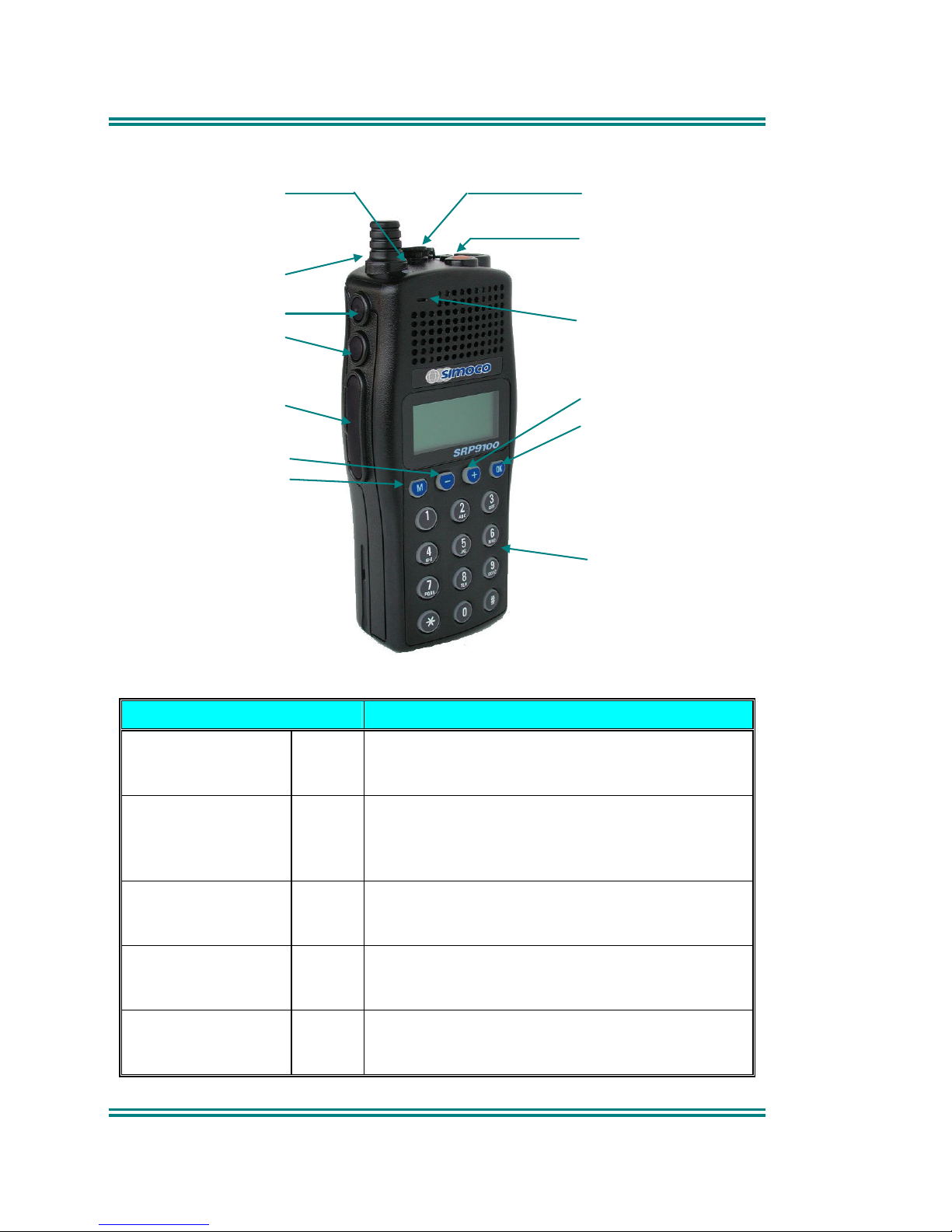
2. FRONT PANEL CONTROLS
Press To Talk Switch
On-Off Volume
Function Button # 5
Function Button # 6
Function Button # 7
Often used as Alarm
Keypad for DTMF or
Channel or Selcall Entry
Function Button # 2
Function Button # 1
Function Button # 3
Function Button # 4
Accessory Socket
Microphone
Indicator LED
Figure 1 – SRP9100 Portable
Button/ Control Function
On/Off/Volume Rotate the switch clockwise to turn on the
radio and then set the volume to the desired
level.
Rx/Tx/Power LED Green LED illuminates when receiving a
signal. Red LED Illuminates when the radio is
transmitting. Flashing Red indicates low
battery.
Keypad Used to dial channel numbers, set status and
send DTMF or Selcall. Note that the
SRP9120 variant does not have a keypad.
Function Button F1 M This button’s function may be configured by
the programmer, it is typically programmed as
the menu select key.
Function Button F2 - This button’s function may be configured by
the programmer, it is typically programmed as
the channel down key
Page 11

SRP9100 ~ PMR Portable Radio User Guide
© Comgroup Australia 2010 3 TNM-U-E-0047 Issue 1.2a
Function Button F3 + This button’s function may be configured by
the programmer, it is typically programmed as
the channel up key
Function Button F4 OK This button’s function may be configured by
the programmer, it is typically programmed as
the Send Channel Encode key. Note that
during menu operations, it becomes a confirm
key.
Special Function F5 This button’s function may be configured by
the programmer.
Special Function F6 This button’s function may be configured by
the programmer.
Special Function F7 This button’s function may be configured by
the programmer, it is typically programmed as
the Alarm/Emergency key
Page 12

SRP9100 ~ PMR Portable Radio User Guide
TNM-U-E-0047 Issue 1.2a Page 4 © Comgroup Australia 2010
3. MENU SYSTEM
The SRP9100 radio software uses a programmed Menu structure to enable
the operator to access all of the radio options. The structure of the menu
(comprising up to thirteen screens) can be programmed to meet the specific
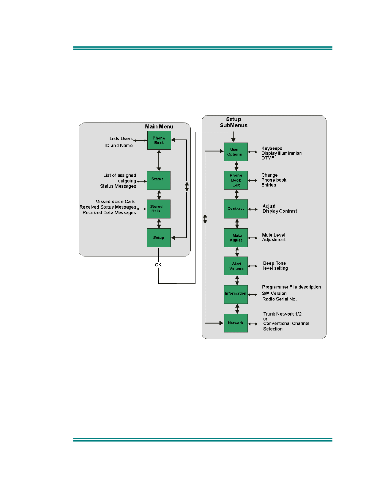
needs of individual customers. Figure 2 illustrates the complete menu
structure of the radio.
Any or all of the Screens can be programmed or hidden with the following
provisos:
• The Phone Book Screen is always programmed in and is the default
Screen displayed.
• The Main Menu provides access to the usual Screens required to operate
the radio.
• The Setup Sub-Menus provide access to the radio setup parameters.
• When options are placed in a Setup Sub-Menu, Setup should be offered
as a sub menu in the Main Menu selection.
• Both the Main Menu and the Setup submenus can each hold up to ten
screens.
Programming of menus is a configuration task normally performed by the
system manager using programmer software.
3.1 M
ENU NAVIGATION
The menu button is normally labelled ‘M’ and enables you to step through all
of the Menu Screens by repeatedly pressing the button.
The menu button may be reassigned to any function key using the field
programmer.
Page 13
SRP9100 ~ PMR Portable Radio User Guide
© Comgroup Australia 2010 5 TNM-U-E-0047 Issue 1.2a
3.2 D
EFAULT SETTINGS
Figure 2 - Menu Navigation
Note that the menu flow shown is an example of the default menu. The menu
options can be configured and changed in the field programmer. Other menu
sequences are possible in your radio.
Pressing the “M” key steps through the
menus on the left. The Set-up sub menu
on the right can be entered by pressing
the “OK” key when Set-up is selected.
Once in the Set-up sub menu, pressing the
“M” key steps through the sub menus. Exit
by reset key or wait for timeout.
Page 14
SRP9100 ~ PMR Portable Radio User Guide
TNM-U-E-0047 Issue 1.2a Page 6 © Comgroup Australia 2010
4. MAIN MENU SCREENS
4.1 C
HANNELS SCREEN
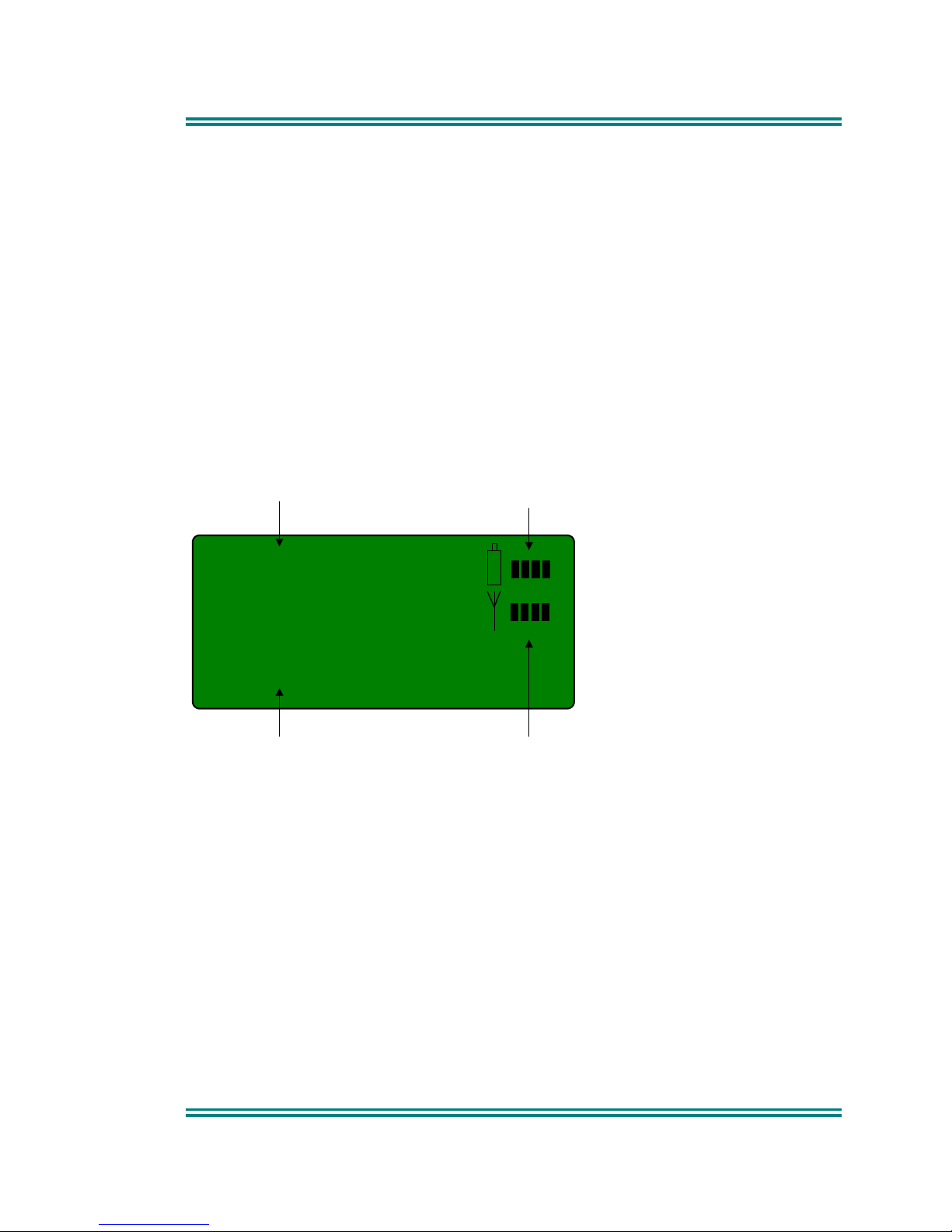
502
Mt Buller
Channel Number
Channel Name Signal Strength (RSSI)
Battery Level
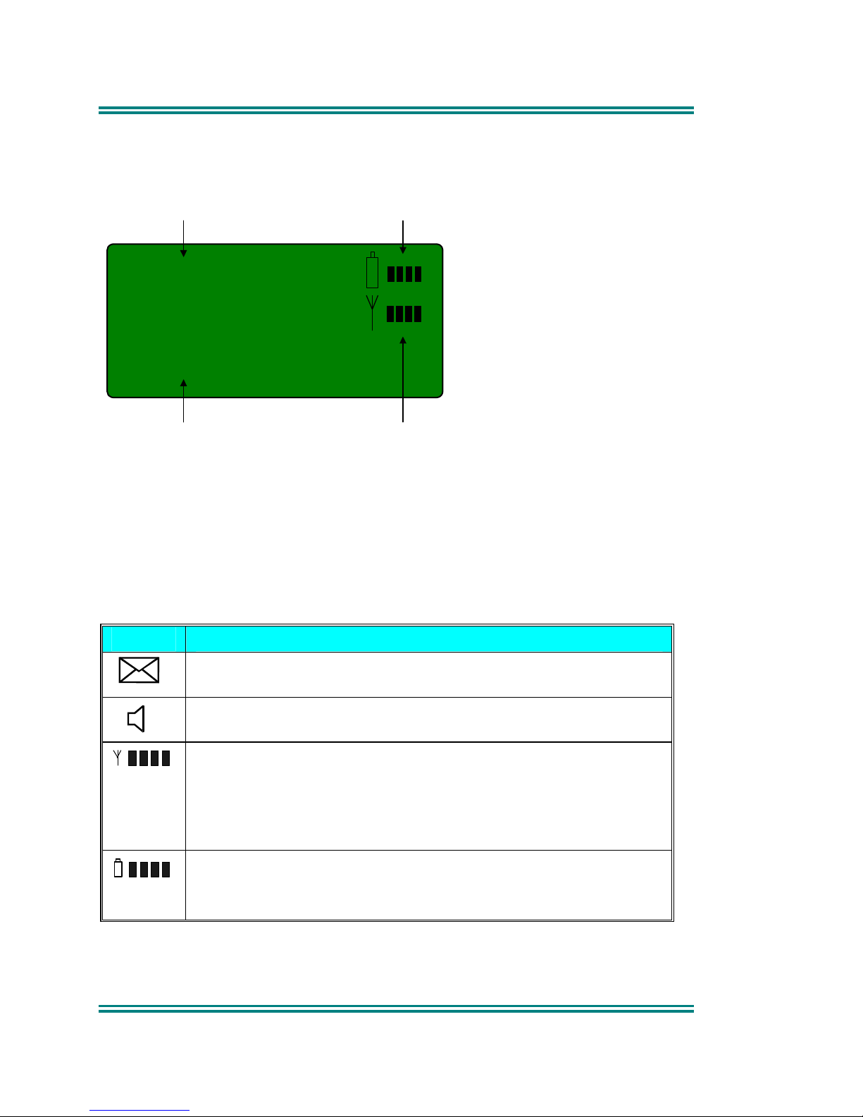
The Channels Screen shows the current channel and allows it to be changed.
The Channel Name shows the text associated with the radio channel.
The RSSI Bars indicate the signal strength of the current channel.
The Battery Level indicates the current battery condition
Several Icons can be displayed as shown below:
ICONS INDICATION
The envelope icon indicates that there are one or more stored
messages.
The outline speaker icon indicates that a signal is present and
the radio is unmuted.
Received Signal Strength Indication (RSSI). A stronger
signal will display more bars.
One bar shown = approx. –118dBm, Two bars = approx. –
106dBm, Three bars = approx. -96dBm, Four bars = approx. –
84dBm.
Battery level indicator. A new battery should display four
bars.
The – and + buttons scroll through the entries within the current Menu Screen
(e.g. Channels).
Page 15
SRP9100 ~ PMR Portable Radio User Guide
© Comgroup Australia 2010 7 TNM-U-E-0047 Issue 1.2a
The Keypad may be used to enter numbers directly, which temporarily appear
on the Message-Line, e.g. Changing channels from the keypad can be done
by entering the channel number and pressing the ‘#’ button. [only available on
keypad version]
Note: If DTMF is enabled then pressing keypad buttons will send the
corresponding DTMF tone. [only available on keypad version]
4.2 P
HONEBOOK SCREEN
This Screen need only be accessed if Selcall is used. Selcall Identity
information is stored for various users and calls can be placed to them from
this Screen.
The -/+ buttons scroll through the Phonebook entries.
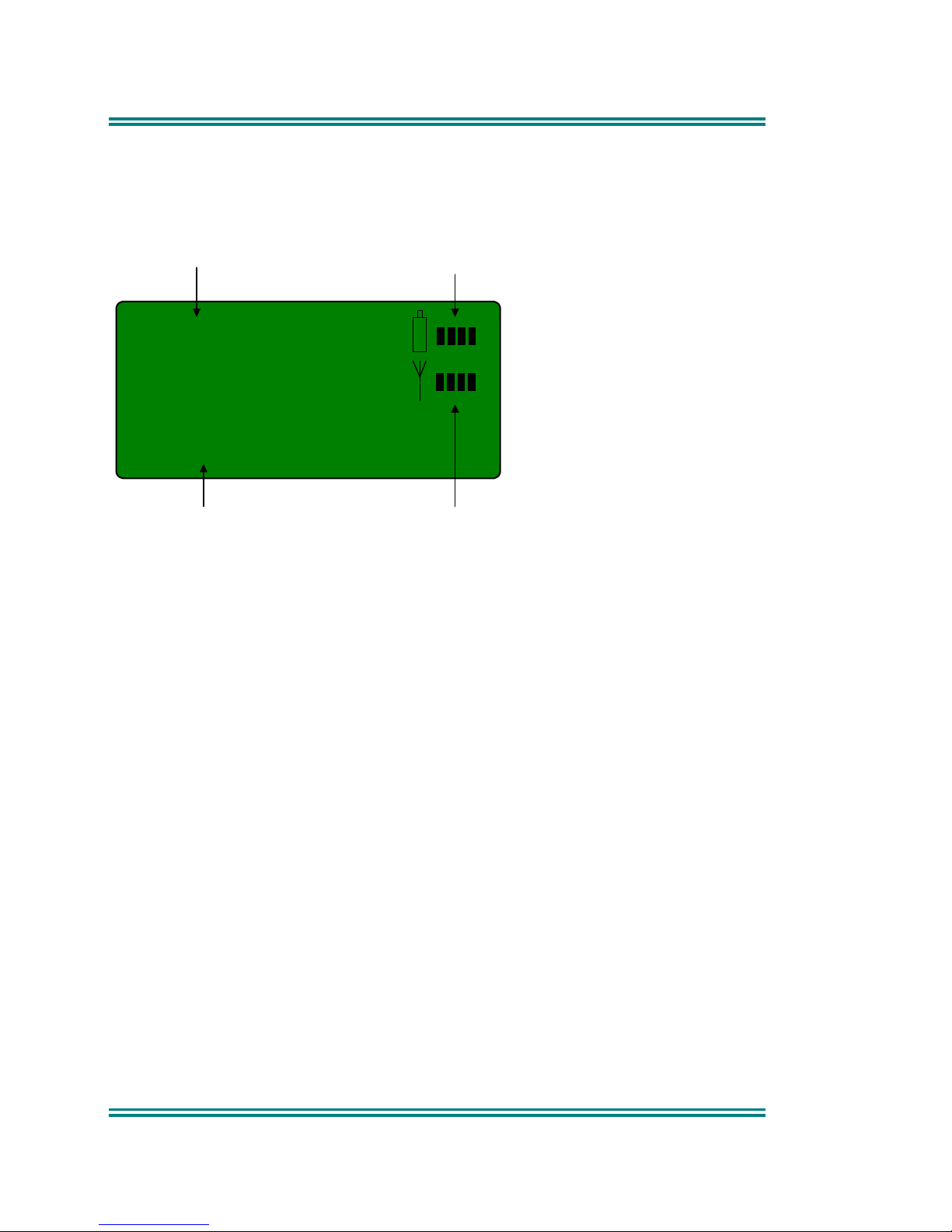
002
J. Wright
Entry Number
Entry Name
Signal Strength (RSSI)
Battery Level
The display will alternately show the name of the entry and the Selcall identity
when viewing a Phonebook entry.
Pressing the OK button will place a call to the displayed identity.
Notes: 1 If the Selcall requires a Status to be included then the Saved-
Status-Value will be used. (See description of Status below.)
2 The Identity shown on the display when this Screen is exited may
be referenced from other Menu Screens and is called the
Current-Phonebook-Entry.
Page 16
SRP9100 ~ PMR Portable Radio User Guide
TNM-U-E-0047 Issue 1.2a Page 8 © Comgroup Australia 2010
4.3 S
TATUS SCREEN
This Screen need only be accessed if Selcall is used. Selcall Status is stored
here and can be sent from this Screen.
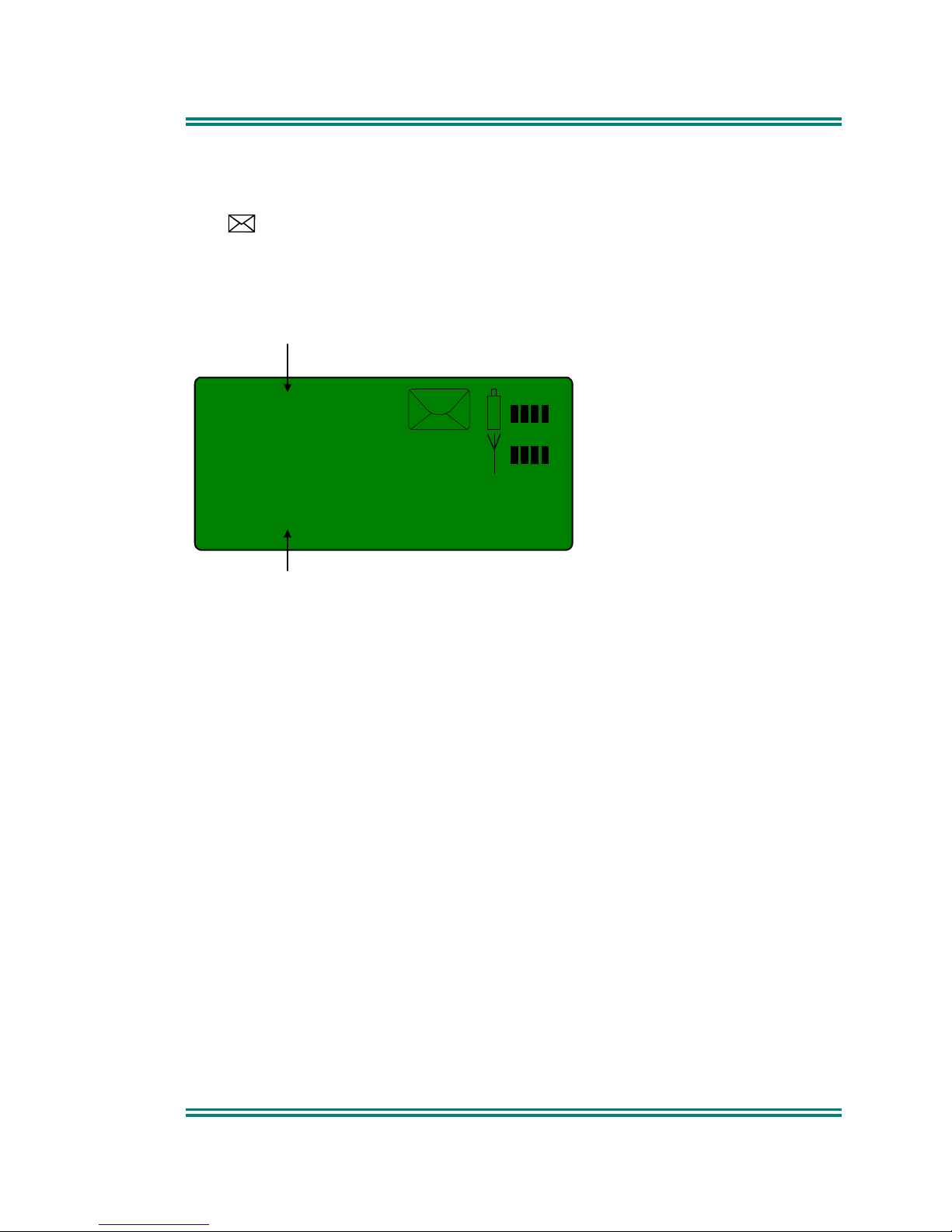
S02
On Route
Status Number
Status Text
Signal Strength (RSSI)
Battery Level
The -/+ buttons scroll through the Status List entries.
Pressing the OK button will send the displayed Status to the Current-
Phonebook-Entry.
Notes: 1 When a Status is sent, it becomes the current Saved-Status-
Value, and can be used at a later time from other Menu Screens.
2 The Saved-Status-Value can also be set from the Channel or
Phonebook Screens by entering the number (from the Keypad)
and pressing the * button. The value is saved but not sent. [only
available on keypad version]
Page 17
SRP9100 ~ PMR Portable Radio User Guide
© Comgroup Australia 2010 9 TNM-U-E-0047 Issue 1.2a
4.4 S
TORED CALLS SCREEN
This screen allows the ten most recent missed Selcalls (ones not answered
before the Alert-tone stops) and received Status Selcalls to be reviewed.
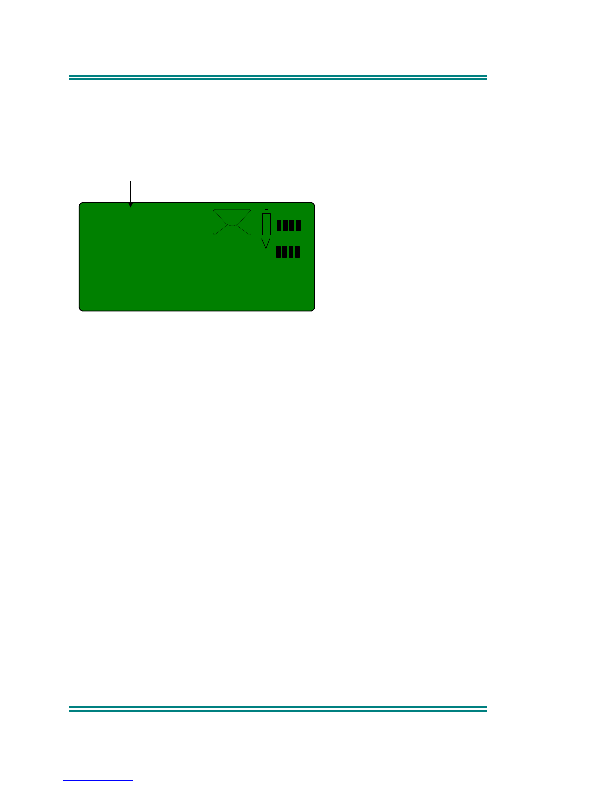
The icon will show in the Main Channel Screen when there is an entry in
this Screen. Note that storing of calls is configurable and must be enabled in
the Field Programmer Selcall decodes menu.
Q02
Warehouse
Stored Call Number
Calling Party Text
The displayed text identifies the caller (e.g. Warehouse). If Status text is
used, (e.g. Call Depot) it will be displayed alternately in the position of the
calling party text.
The displayed number (Q02) shows the queued position of the entry. The
most recent call is shown whenever this Screen is displayed.
Press the -/+ buttons to scroll through other Stored Calls.
Press the OK button to Selcall that caller.
Press the assigned Reset key to return to the Channel Screen without
making a call.
Note that the Stored Calls Screen will eventually time out and return to the
Channel Screen.
Page 18
SRP9100 ~ PMR Portable Radio User Guide
TNM-U-E-0047 Issue 1.2a Page 10 © Comgroup Australia 2010
4.5 S
END MESSAGE SCREEN
This Screen allows the user to send a free form text message to another radio
user in a similar manner to a cell phone SMS.
M7
Send Message
Memory Entry Number
(defined by FPP)
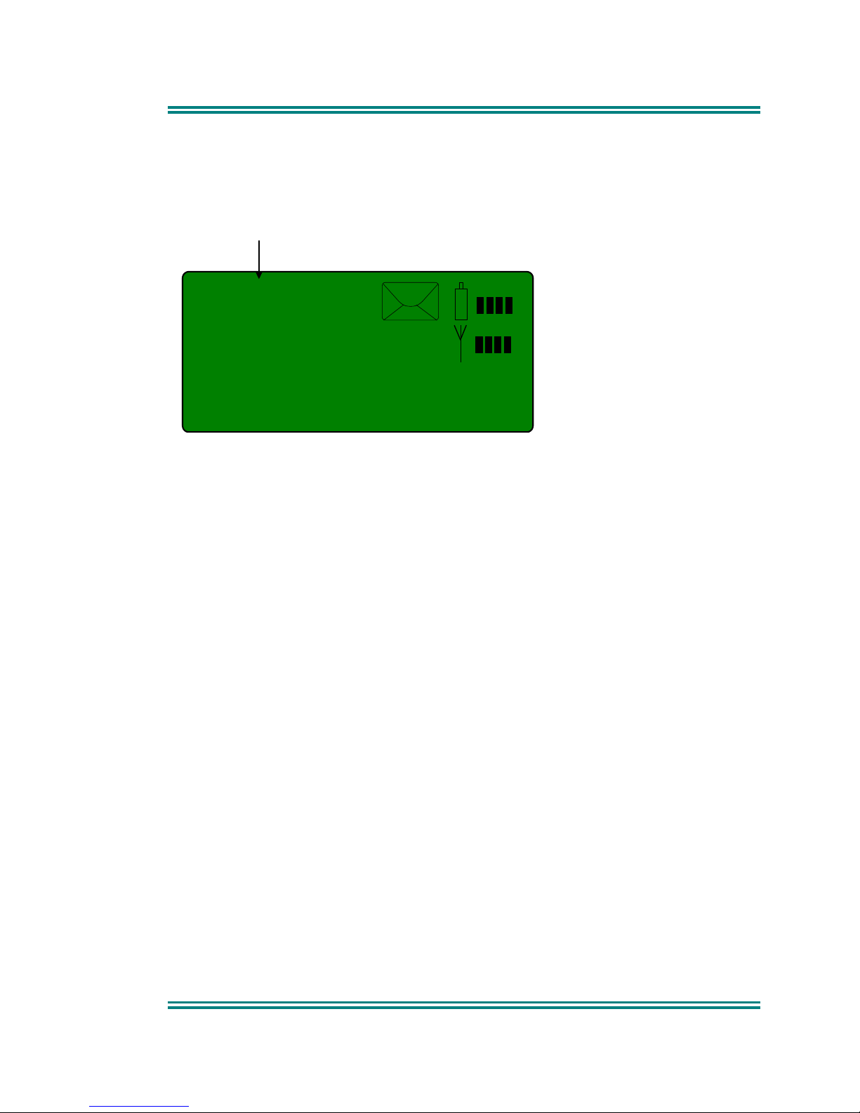
Upon selecting the Send Message menu option with the OK button, a flashing
cursor will appear on the lower left hand corner of the screen.
Each key is labelled with up to 3 text characters. The text characters are
entered by pressing the keypad key once for the first character, twice for the
second and three time for the third.
After a short delay, the cursor will advance for the next character entry.
To move the cursor left or right, use the -/+ buttons.
To delete a character, move the cursor over the character and then press the
function key that is programmed with the Reset function.
When the message is complete, press the OK button to send it. The screen
will then ask for the address to send it to with “Enter No.” Enter the address
and then press OK. The message will be sent.
Page 19
SRP9100 ~ PMR Portable Radio User Guide
© Comgroup Australia 2010 11 TNM-U-E-0047 Issue 1.2a
4.6 S
ETUP SCREEN
Use this Screen to access the other Set-up submenus.
M10
User Options
Memory Entry Number
(defined by FPP)
Press (OK) button to show the first of the submenus, and then the -/+
buttons to scroll through these screens.
The actual set-up submenus available will depend on the configuration by the
Field Programmer.
These can include:
• Screen Contrast
• Phone Book Edit
• Mute Adjust
• Alert Volume
• Network
• Info
• User CTCSS
• Received Signal Strength Indication (RSSI)
Refer to section 6 for a description of these functions.
Page 20

SRP9100 ~ PMR Portable Radio User Guide
TNM-U-E-0047 Issue 1.2a Page 12 © Comgroup Australia 2010
5. COMMON FUNCTIONS AND FACILITIES
5.1 S
WITCH-ON/SWITCH-OFF
Turn the On/Off/Volume Knob clockwise to switch the portable radio ON.
The display will illuminate and show a ‘Welcome Message’ and the Selcall
Identity of the portable radio.
After a brief time the display will revert to the Channel Screen, at which time
the portable radio is ready for use.
Turning the On/Off/Volume knob anticlockwise will switch the portable radio
off.
If the radio Inactivity Timer is enabled, the portable radio will automatically
turn off after several hours of inactivity (i.e. no buttons pressed).
The radio will emit warning beeps for 10 seconds prior to switching off.
Pressing any button will reset this timer.
5.1.1 Volume Adjustment
The Volume Control adjusts the speech level at the loudspeaker or remote
speaker microphone. Rotating clockwise increases the volume and anticlockwise decreases the volume.
Note: The radio may be programmed so that the volume cannot be turned off
completely.
Page 21
SRP9100 ~ PMR Portable Radio User Guide
© Comgroup Australia 2010 13 TNM-U-E-0047 Issue 1.2a
5.2 R
ECEIVING
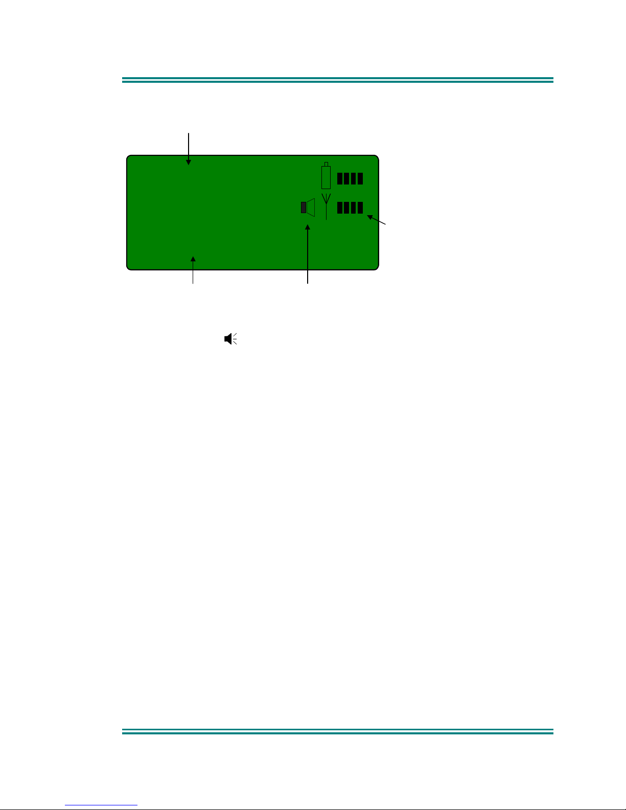
502
Mt Buller
Channel Number
Channel Name Signal Received
Received
Signal Strength
(Scan / Vote)
The portable radio will listen on the displayed Channel.
The Speaker Icon will show when a valid signal is being received and audio
will be heard at the Loudspeaker.
Changing channels can be achieved by any of the following:
• Pressing the -/+ buttons.
• Entering the desired channel number from the Keypad and pressing #
(e.g. 12#) [only available on keypad version].
• Pressing a Go-to-Channel Function Button, refer to Section 7.11.
Note: If the displayed channel is a Vote or MultiAx channel then the received
signal strength display will change to scanning. In this mode, a signal
bar will move left and right until a signal is found. When stopped on a
channel, the channel name will be displayed.
Page 22

SRP9100 ~ PMR Portable Radio User Guide
TNM-U-E-0047 Issue 1.2a Page 14 © Comgroup Australia 2010
5.3 T
RANSMITTING
To avoid interfering with other users of the channel, listen first to ensure no
transmissions are occurring. Make sure that the Speaker Icon is not shown.
Hold the portable a few centimeters from the mouth, press the “Press to talk”
(PTT) switch and note that the Tx-LED is RED. Speak clearly across the face
of the portable in a normal conversational manner. Note that the microphone
is on the top left hand side of the radio.
In most systems it is important to wait a short time between pressing PTT and
commencing to speak. This ensures that the path is properly established and
avoids lost or distorted speech.
Use the correct operating procedure and keep transmissions short.
Release the PTT switch as soon as the message is finished.
Notes: 1 A channel may be programmed as “Receive-only” or “Transmit
Inhibit” may be programmed which disallows PTT while the radio is
receiving a signal. A continuous tone will be heard if PTT is
attempted.
2 A Transmit Limit Timer may be set-up that limits a continuous
transmission on a channel. The last 10 seconds before the timer
expires may be accompanied by warning tones.
3 The radio may be programmed to send a Selcall (ANI) when the
PTT is pressed or released. This may introduce a short delay
before the microphone is enabled or after PTT is released.
Page 23
SRP9100 ~ PMR Portable Radio User Guide
© Comgroup Australia 2010 15 TNM-U-E-0047 Issue 1.2a
5.4 SELCALL F
UNCTIONS
5.4.1 Receiving a Selcall
A number of different options can be set up by your dealer to sound various
alert tones when a selcall is received. Consult your dealer for a detailed
explanation of your radios set up.
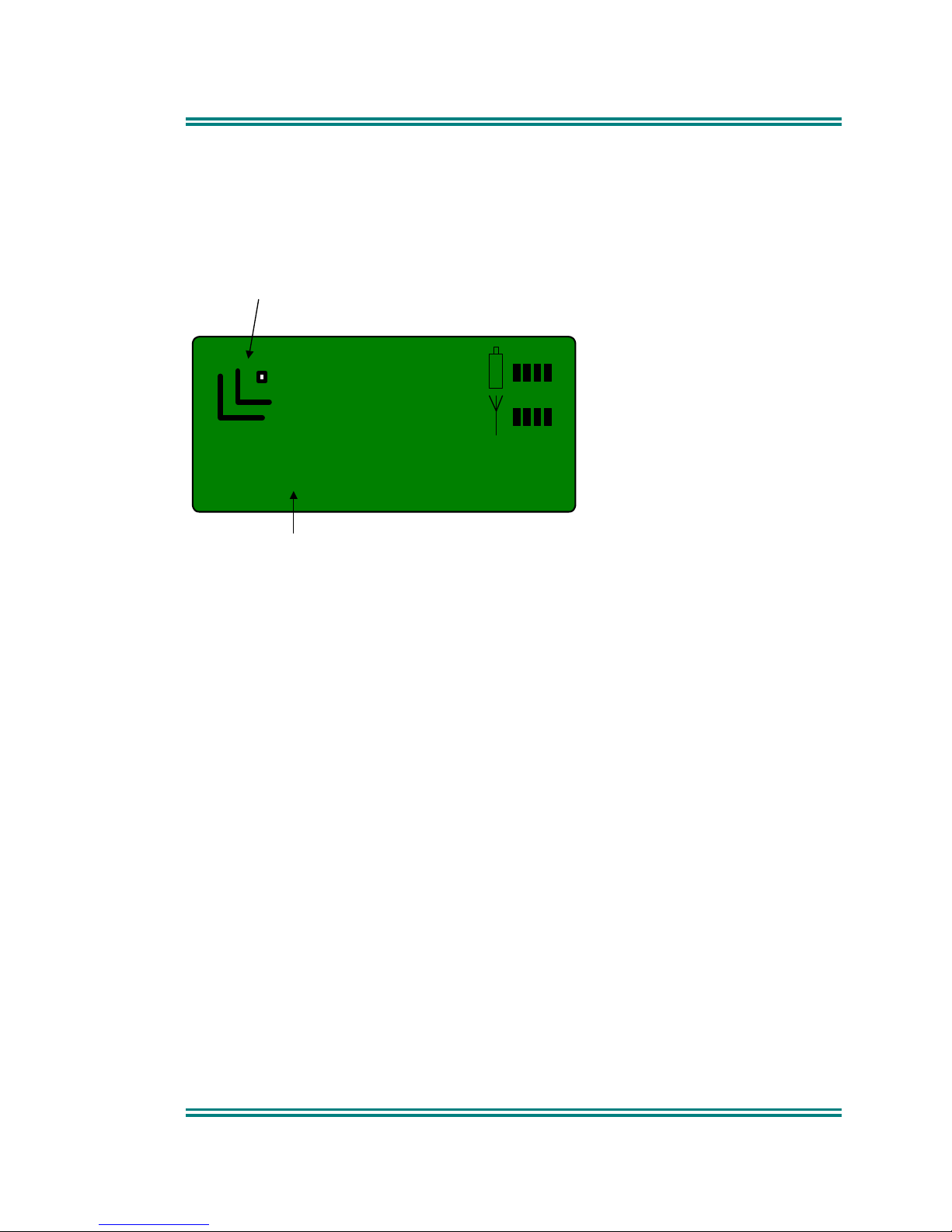
Warehouse
Selcall Received Icon
Caller
When a Selcall is received the radio may respond by:
• Showing a flashing or solid icon to indicate that the radio has been
Called,
• sounding an Alert tone, or
• Displaying the Name of the caller (if it exists in the Phonebook) or the
numerical identity of the caller (if unknown) in the Name field.
Pressing the OK button to call the party back or pressing Reset will clear the
icon and stop the Alert tone.
5.4.2 Sending a Selcall
Refer to sections on Phonebook Screen (page 7) and Status Screen (page 8)
for methods of sending a Selcall.
5.4.3 Other Selcall Functions
The SRP9100 series has several other functions that affect how the radio
operates with received signals or selcalls. These are described later in this
booklet under the headings:
Monitor/Reset (refer to Section 7.1)
Reset (refer to Section 7.3)
Page 24

SRP9100 ~ PMR Portable Radio User Guide
TNM-U-E-0047 Issue 1.2a Page 16 © Comgroup Australia 2010
Transpond Enable (refer to Section 7.6)
Send-1, Send-2 (refer to Section 7.5)
Special Encode1...8 (refer to Section 7.10)
Page 25
SRP9100 ~ PMR Portable Radio User Guide
© Comgroup Australia 2010 17 TNM-U-E-0047 Issue 1.2a
5.5 S
CAN FUNCTIONS
Scanning consists of sequentially searching up to 16 channels for a valid
signal (RF, CTCSS or DCS tone). When found, the radio will stop on that
channel until the signal disappears again.
While listening on the channel, the User can PTT on that channel. After the
signal disappears the radio will remain listening on the channel for a short time
(typically 3 seconds) before resuming scanning.
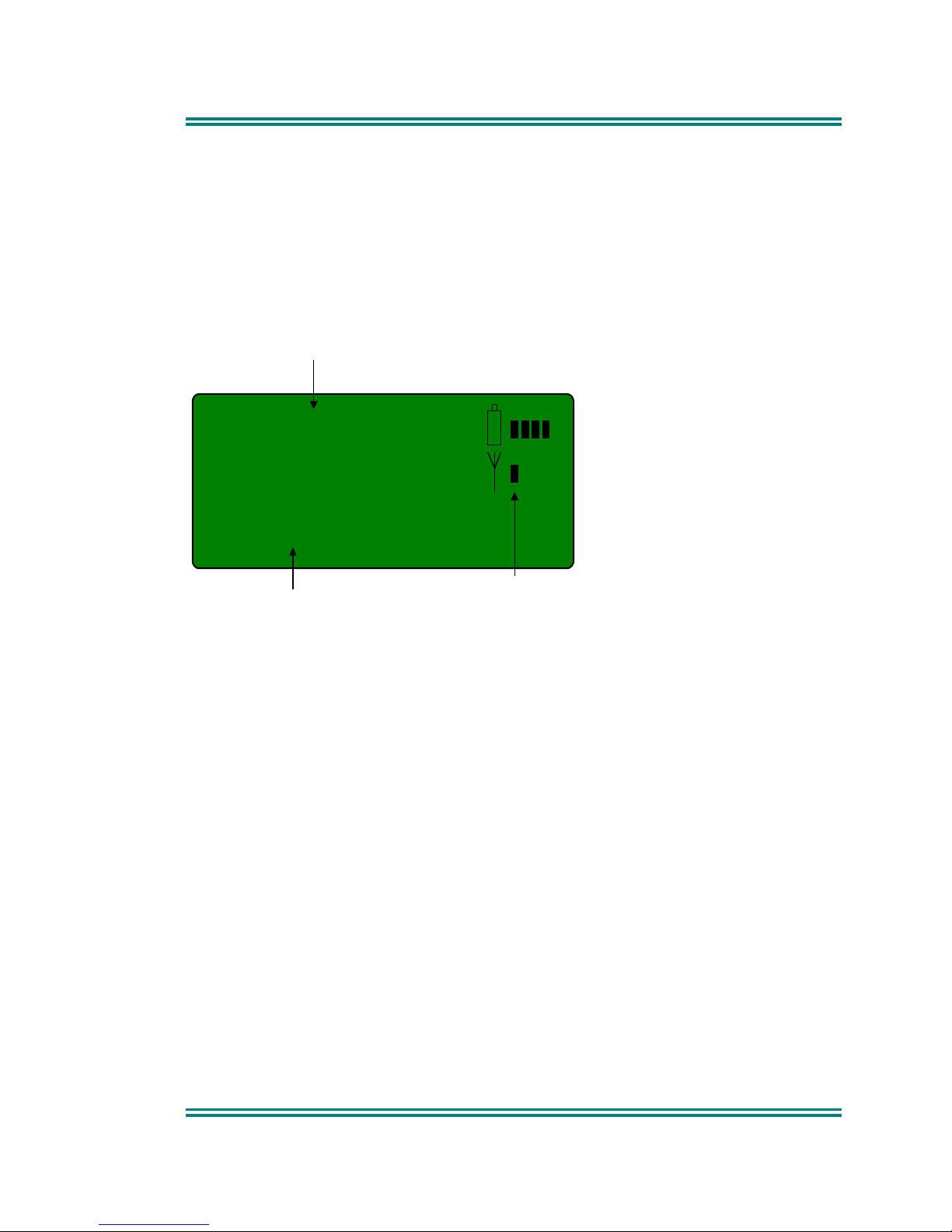
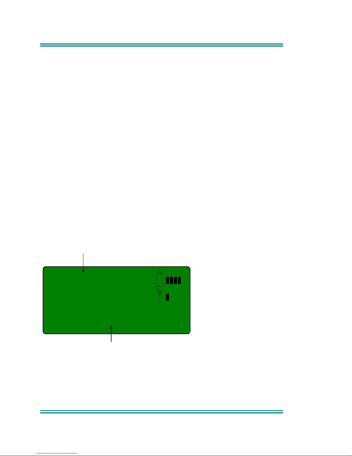
502
Scan 23
Scan Channel Number
Scan Group Name
Scan/Vote modes are indicated by
bar moving from left to right and back
If a Priority/Emergency Channel is assigned, the radio will interleave a check
of this channel between each normal channel check. The radio may also
check the Priority Channel every few seconds while stopped on a channel. If
a signal is found on the Priority Channel then the radio will switch to that
channel immediately.
To activate Scanning, select a channel that has been programmed as a scan
channel. Consult your dealer for your customised button configuration.
5.5.1 Scan Screen
The display shows the name of the current Scan Channel (e.g. “Scan 23”),
which can be changed using the -/+ buttons. This will take the radio to other
channels which may be either Scan Channels or Normal Channels depending
on the radio’s configuration.
The RSSI indicator shows scanning in progress by moving the bar back and
forwards.
When stopped on a channel, the lower line shows the name of the selected
site, and the scanning indicator is replaced by the signal strength display.
The assigned Reset function button temporarily deletes the channel from the
Scan-Group. Skipped channels are restored when a different Scan Group is
Page 26
SRP9100 ~ PMR Portable Radio User Guide
TNM-U-E-0047 Issue 1.2a Page 18 © Comgroup Australia 2010
selected or if the Scan Channel is re-selected. The Priority Channel cannot
be skipped.
Scan groups may be assigned as user scan groups using the field
programmer. There may be up to 4 user scan groups.
If a scan group is assigned as a user scan type, the user is able to edit the
channels in the scan group from the keypad [only available on keypad
version].
The user can then enter the edit submenu for that group be pressing the * key.
Editing is described in the next section.
While listening on the channel, the User can PTT on that channel. After the
signal disappears the radio will remain listening on the channel for a short time
before resuming scanning.
The Keypad may be used for quick channel change (e.g. 456#) while the radio
is scanning.
5.5.2 Scan-Edit Screen
[keypad version only].
If the current channel is a scan channel and that scan channel has been
assigned as a user editable scan channel, it may be edited by pressing the *
key. The sub menu screen is shown below.
502
0Del 1Ad 2 Pr
Scan Channel Number
User Scan Sub Menu
The scan edit sub menu shows the keys that are available to modify the scan
group.
To delete a channel from the scan group, press 0 followed by the channel to
delete and then #. To delete channel 14, press 014#. The display will briefly
show “deleted” and return to scan mode.
Page 27

SRP9100 ~ PMR Portable Radio User Guide
© Comgroup Australia 2010 19 TNM-U-E-0047 Issue 1.2a
To add a channel to the scan group, press the 1 key followed by the channel
to add, and then the # key. To add channel 34, press 134#.
To change the priority channel, press the 2 key followed by the new priority
channel group, and then the # key. To change the priority channel to 21,
press 221#.
The radio will attempt to save the old priority channel into the scan group so
that it is not lost. If there is not room in the scan group to save the priority
channel, the portable will sound an error beep.
5.6 MUTE L
EVEL SETTING
When the Mute Adjust Screen is selected, the -/+ buttons allow the displayed
Radio Mute level to be adjusted. The big number in the top left is the current
mute level. The level is stored when the Screen is exited.
5.7 DTMF O
PERATION
When DTMF is enabled, DTMF tones can be sent using the Keypad from the
Main Channel Screen at any time while the PTT is pressed. Pressing 0...9, *
and # will send the associated tones providing PTT is on.
The programmer sets the tone period and gap.
DTMF can be enabled via the DTMF option in the User-Options sub-menu
under the SETUP Menu (refer to Section 6).
5.8 K
EYPAD LOCK
The radio has a keypad lock function that may be enabled by the field
programmer during configuration. If this function is activated, a key icon will
be displayed in the top left-hand side of the display when locked.
To unlock the keypad, it is necessary to press and hold down the OK key for 2
seconds. After 2 seconds, the key icon will disappear and the keys will be
enabled.
The keypad will automatically re-lock after a period of 10 seconds following no
key activity.
Page 28

SRP9100 ~ PMR Portable Radio User Guide
TNM-U-E-0047 Issue 1.2a Page 20 © Comgroup Australia 2010
6. SETUP
The Set-up sub-menus allow the operator to edit/modify the operation of some
of the general functions of the radio. The programmer can restructure or
restrict access to any or all of these menus and may restructure them
according to specific requirements.
6.1 SET-
UP SUB-MENUS
The Set-up sub-menu structure programmed at manufacture is shown in
Figure 2. These sub-menu Screens provide access to operator functions as
follows.
User Options Key beeps, Backlight, Dual Watch & DTMF on/off
selection.
Mute Adjust Mute Level adjustment.
Phone Book Edit Allows Phonebook entries to be changed, deleted or
added.
Contrast Display contrast adjustment.
Alert Volume Beep tone level setting (relative to Audio Volume).
Radio Information Programmer File description, SW version and Serial
Number.
Network Trunk Network-1/2 or Conventional Channel selection.
Page 29
SRP9100 ~ PMR Portable Radio User Guide
© Comgroup Australia 2010 21 TNM-U-E-0047 Issue 1.2a
6.1.1 User Options
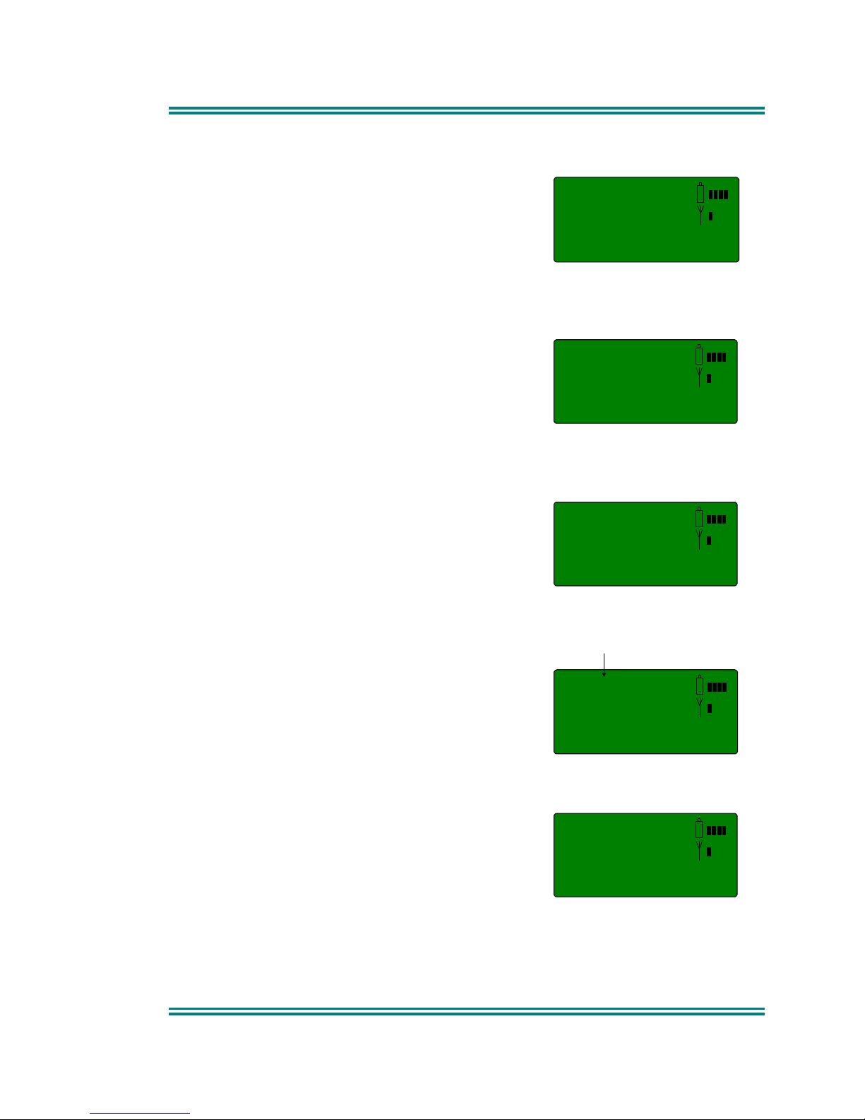
The User Options Screen allows the Keybeeps,
Backlight, Dual Watch and DTMF facilities to be
set On or Off. Use the -/+ buttons to scroll
between the different facilities.
The OK button toggles the selection On/Off.
The setting is saved on exit.
6.1.2 Mute Adjust
Use the Menu Screen to view and change
current Mute setting.
Use the -/+ buttons to change the Mute level.
Use the OK button to return to the Channel
Screen.
6.1.3 Phone Book Edit
This Screen allows you to delete or edit Phone
Book entries, or add a new entry.
6.1.3.1 ADD ENTRY
Select Phone Book Edit from Setup sub menu
and press OK.
The next available entry number is displayed.
Use the keypad to type the dialstring for the new
entry.
To backspace and delete the digit at the cursor,
press the assigned reset function key.
Press (OK) to accept the number and display the
next screen.
Use the keypad to type the name (refer to
Section 6.1.3.4).
Press (OK) to accept the name and go to the
Main Channel Screen.
On
Key Beeps
04
Mute Adjust
006
Enter No.
Next Free Entry
M11
Ph Book Edit
006
Enter Text
Page 30

SRP9100 ~ PMR Portable Radio User Guide
TNM-U-E-0047 Issue 1.2a Page 22 © Comgroup Australia 2010
6.1.3.2 DELETE AN ENTRY
Bring up phone book edit on the screen as for add entry and press the -/+
keys to select the entry to delete.
When the chosen entry is displayed, press the OK key. The number will be
now displayed. Press the assigned reset key until all the digits are deleted.
Press OK.
The text name will be displayed. Move the cursor to the start of the text and
press the space key 0. Move the cursor to the next key and repeat until all
characters are erased. Press OK.
6.1.3.3 EDIT AN EXISTING ENTRY
Bring up phone book edit on the screen as for add entry and press the -/+
keys to select the entry to edit.
Once the chosen entry is displayed, press the OK key to edit. To backspace
and delete the digit at the cursor, press the assigned reset key.
Edit the name, refer to Section 6.1.3.4.
Press (OK) to accept the changes.
6.1.3.4 USING THE KEYPAD FOR ALPHANUMERIC TEXT
When using the keypad to type text:
• press the appropriate keypad button a number of times until the
desired character or number is selected,
• the current character space is identified by a flashing block cursor,
• use */# to select lower/upper case letters, respectively,
• use the 0 key to insert a space,
• use the -/+ buttons to move to the next or previous character space to
be entered/modified, and
• Press (OK) to accept and go to the next Screen.
Page 31
SRP9100 ~ PMR Portable Radio User Guide
© Comgroup Australia 2010 23 TNM-U-E-0047 Issue 1.2a
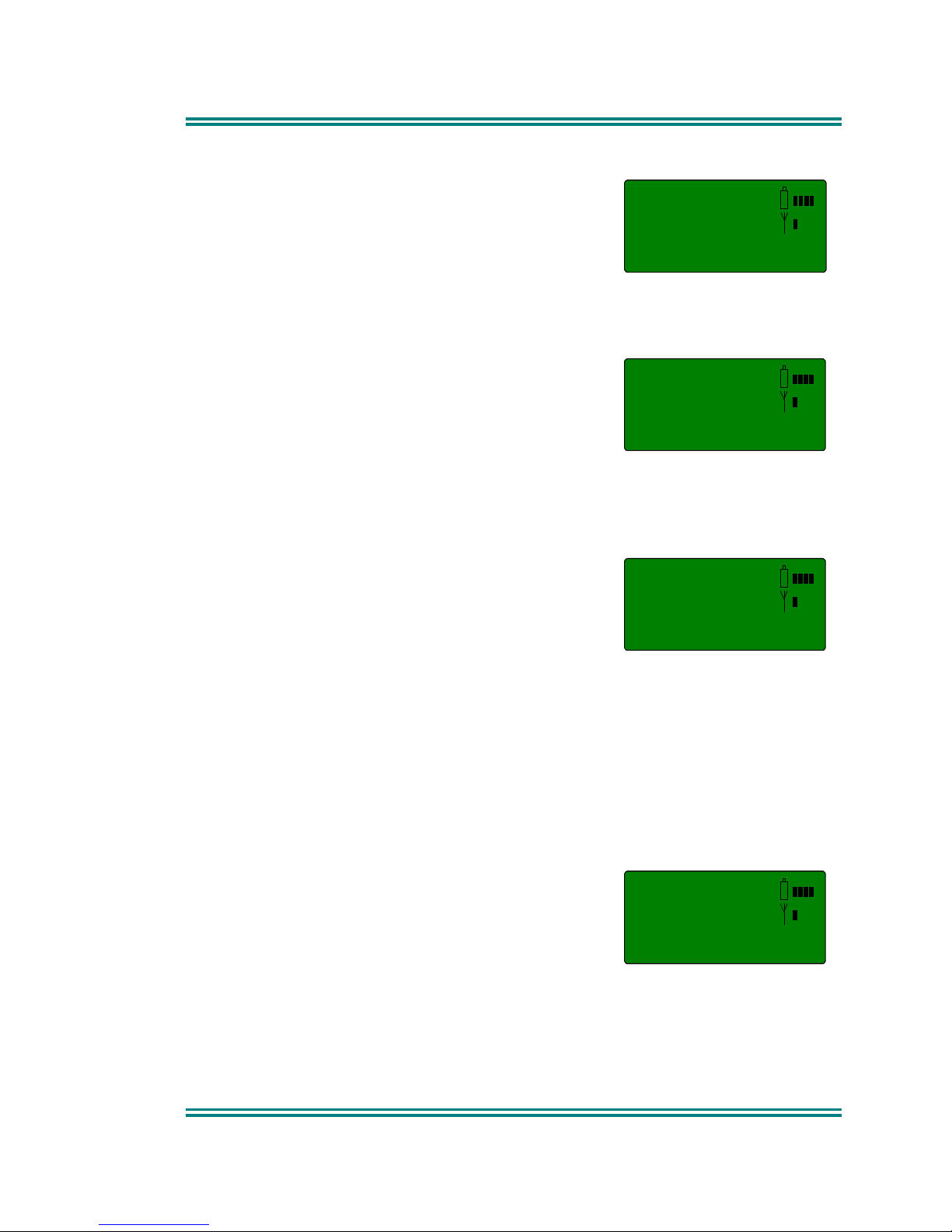
6.1.4 Contrast
The Contrast Screen allows you to set the
contrast level of the Display in the range from 0
to 15.
Use the -/+ to select the required level.
Press OK to accept the setting and go to the
Channel Screen.
Note: this option currently not available.
6.1.5 Alert Volume
This Screen allows you to set the level of the
Alert Volume Beep Tone in relation to the current
Volume setting. The level can be set in 63 steps
over the range -31 to +30, with 0 being about the
same as the voice level.
Use the - /+ buttons to change the relative alert
level. The beep will sound at the indicated level
each time the setting is changed.
Press OK to accept the setting and go to the
Channel Screen.
Note: A minimum Alert Level may be set to
ensure the Alerts can always be heard
from the speaker.
6.1.6 Information
This Screen displays information that identifies the Programmer File
description, Software Version and Radio Serial Number.
This is a read only Screen, press OK to go to the Channel Screen.
6.1.7 Network
The Network Screen allows you to switch
operation between;
• Trunk Network 1
• Trunk Network 2 or
• PMR.
Use the -/+ buttons to make your selection.
Press OK to accept that selection and go to the selected mode.
Refer to the Trunk Operating Instructions for Trunk operation.
M12
Contrast
M14
Alert Volume
-02
Alert Volume
NW1
Network 1
Page 32

SRP9100 ~ PMR Portable Radio User Guide
TNM-U-E-0047 Issue 1.2a Page 24 © Comgroup Australia 2010
7. SPECIAL FUNCTION BUTTONS
This section lists Functions that may be programmed to the F1, F2, F3, F4, F5
F6 or F7 buttons.
Consult your Simoco Dealer for which functions have been programmed in to
your radio.
7.1 M
ONITOR
Opens/Closes the audio (signaling) mute.
Only valid on Non-Community Repeater type channels and/or Closed Selcall
channels without Receiver Lock-out programmed.
7.2 S
QUELCH DEFEAT
Opens/Closes the squelch (carrier) mute.
7.3 R
ESET
Closes the audio (signaling) mute on closed Selcall Channels.
7.4 S
CAN
Activate Scanning, refer to Section 5.5.
7.5 S
END
-2
Sends a specific selcall sequence.
7.6 T
RANSPOND DISABLE
Disables Individual Call Acknowledge. When pressed, a single beep indicates
on and two beeps indicate off.
7.7 CTCSS
Defeats the CTCSS mute on the channel
Only valid on Non-Community Repeater type channels and/or Open Selcall
channels.
7.8 M
UTE
Provides direct access to the Mute Setup screen (refer to Section 6.1.2) and
allows the user to change the mute level from that screen.
7.9 G
OTO CHAN
A, B, C, D
Selects predefined Channel A, B, C or D, and may return on the second press.
The Defined Channel may be redefined if held for approximately 2 seconds.
Field programmer configuration will affect the previously described behaviour.
7.10 S
PECIAL ENC
1…8
Sends Special Encode 1, 2, … 8
Page 33

SRP9100 ~ PMR Portable Radio User Guide
© Comgroup Australia 2010 25 TNM-U-E-0047 Issue 1.2a
7.11 A
LARM
Put the mobile into Alarm mode.
7.12 R
EPEATER DEFEAT
Allows the radio to transmit on the reverse frequency on a Repeater Channel.
When the button is pressed again (or the Channel is changed) the transmit
frequency reverts to the original setting.
Repeater defeat mode is indicated to the user by a single beep at the start of
each PTT.
7.13 L
OW POWER
Forces the radio to low power.
Pressing again puts the radio back to the power level defined for the current
channel. This is not affected by Channel changes.
When pressed, a single beep indicates low power mode and two beeps
indicate low power mode off.
7.14 C
HANNEL UP AND DOWN
These functions change channels in the upward or downward directions.
7.15 S
END CHANNEL ENCODE
Sends the encode that has been defined for that particular channel.
7.16 S
END
DTMF 1
AND
2
This function sends the predefined DTMF tone sequence that had been
previously set in the Field Programmer.
7.17 U
SER
CTCSS
If enabled by the Field Programmer, this function will allow the user to select
the CTCSS tone to be used.
7.18 S
CRAMBLER ON/OFF
If enabled by the Field Programmer, this function toggles the state of the
speech scrambler. When active, there will be a short audible tone at the start
of PTT to inform the user of the scrambler activation. Each time the key is
pressed, the display will show 'On' and 'Off'.
Page 34

SRP9100 ~ PMR Portable Radio User Guide
TNM-U-E-0047 Issue 1.2a Page 26 © Comgroup Australia 2010
8. OPTIONS
The following options are available, contact your dealer for further information.
8.1 H
IGH CAPACITY BATTERY
This battery can be used where there are more demands on the time that the
radio must be operational, or where transmissions are more frequent.
Capacity of 2700mAH
8.2 M
ID CAPACITY BATTERY
Mid sized capacity battery for the portable. 2100mAH Capacity.
8.3 S
INGLE POCKET CHARGER
Charger capable of charging one portable radio at a time.
8.4 F
OUR POCKET CHARGER
Charger for up to four portable radios at once.
8.5 V
EHICLE MOUNTED CHARGER
Charger for in vehicle charging of the portable.
8.6 L
IGHTWEIGHT CARRY CASE
Carry case for light duty use.
8.7 H
EAVY DUTY CARRY CASE
Carry case for heavy duty use with belt loop attachment.
8.8 S
HOULDER STRAP
Shoulder strap that fits on portable.
8.9 L
IGHTWEIGHT LAPEL SPEAKER MICROPHONE
Combined small speaker and microphone for light duty use.
8.10 M
EDIUM WEIGHT LAPEL SPEAKER MICROPHONE
Combined speaker and microphone for heavier duty use.
8.11 H
EAVY DUTY LAPEL SPEAKER MICROPHONE
Combined speaker and microphone for heaviest duty use.
8.12 L
IGHTWEIGHT HEADSET
Headset with boom microphone with PTT button.
8.13 E
ARPIECE
Earpiece for portable radio.
Page 35

SRP9100 ~ PMR Portable Radio User Guide
© Comgroup Australia 2010 27 TNM-U-E-0047 Issue 1.2a
9. TROUBLESHOOTING
If, after reading this guide, you are unable to switch the radio on, check that
the battery is charged and correctly attached.
If these checks are OK, contact your dealer or SImoco representative for
further advice.
Page 36
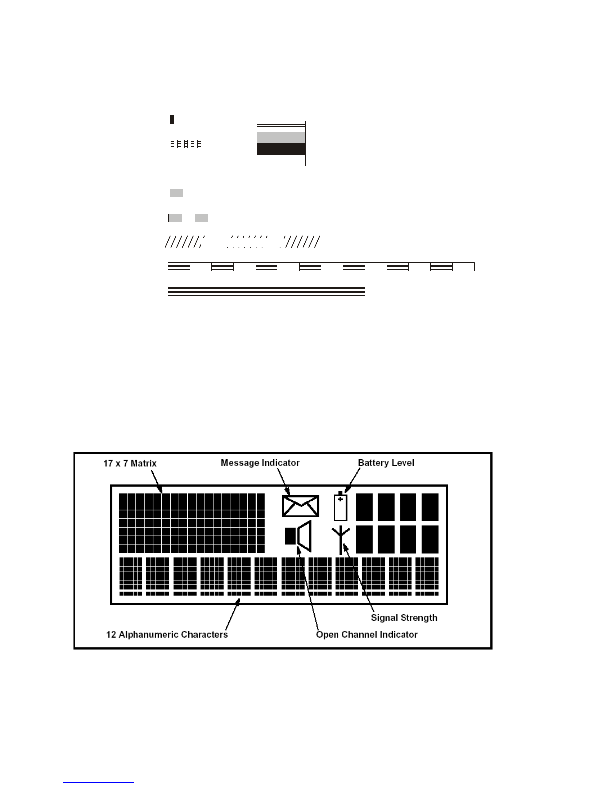
Appendix A - Alert Tones and Messages
Figure 3 - Alert Tones
Appendix B – LCD Display Layout
Key Beep
Error Tone
Beep Alert
Bip Alert
Ring Alert
Urgent Alert
Continuous Alert
2 x Bip Alert
0.05
9000_52
0.10
0.05
0.10
0.10
Continuous
Telephone Ring Tone
0.19
Duration Indicated in seconds
880 Hz
Off
1480 Hz
440 Hz
Page 37

SRP9100 ~ PMR Portable Radio User Guide
© Comgroup Australia 2010 1 TNM-U-E-0047 Issue 1.2a
Appendix C - Glossary
A summary of common radio terms and some other terms used in this
document, and their meanings, are given below.
Alert tones
The transceiver emits these tones to indicate an
invalid operator or error.
Cradle
The bracket that holds the microphone when it is
not in use (on hook).
Current
Phonebook Entry
Name that would be shown were the Phonebook
screen shown.
DSP
Digital Signal Processor.
DTMF Dual Tone Multi-Frequency (Signaling Method).
LCD
Liquid crystal display.
MIC
Abbreviation for microphone.
MPT1327
Refers to the UK Ministry for Post and
Telecommunications specification defining the low
level protocol for public trunking systems.
MPT1343
Refers to the UK Ministry for Post and
Telecommunications specification defining the User
Interface for radios operating on MPT1327 public
trunking systems.
Network
The trunking infrastructure and all its
interconnections.
PTT
Press-to-Talk. Hold down the Press-to-talk switch
on the microphone for the duration of the
transmission.
RF Radio Frequency.
RSSI Received Signal Strength Indicator
Saved Status
Value
The last Status that was sent, entered or optionally
received.
 Loading...