

Page 1
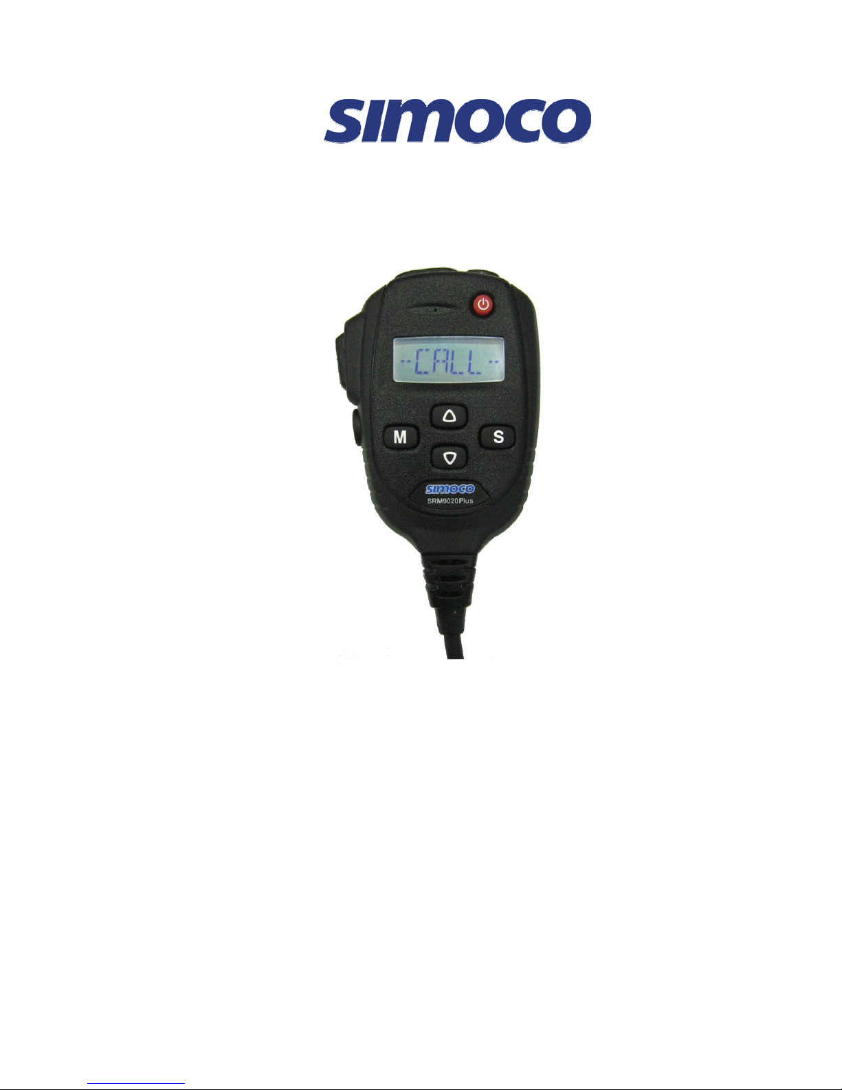
SRM9020plus Mobile Radio
Conventional PMR
Operating Instructions
TNM-U-E-0086 Issue 1.0a
January 2010
Comgroup Australia Pty. Ltd.
1270 Ferntree Gully Road
Scoresby
Victoria, 3179
Australia
Page 2

Page 3

SRM9020plus ~ PMR Operating Instructions
© Comgroup Australia 2010 Page i TNM-U-E-0086 Issue 1.0a
ASSOCIATED DOCUMENTATION
The following documentation is available for use with the SRM9000 series of
products:
TNM-I-E-0005 SRM9000 Series Installation Instructions
TNM-M-E-0001 SRM9000 Service Manual
TNM-U-E-0003 SRM9030 PMR Operating Instructions
TNM-U-E-0004 SRM9030 Trunked Operating Instructions
TNM-U-E-0012 SRM9020 Trunked Operating Instructions
TNM-U-E-0014 SRM9025 PMR Operating Instructions
TNM-U-E-0015 SRM9025 Trunked Operating Instructions
To order copies of any of the above publications, or any other Simoco product,
contact Comgroup Australia on +61 3 9730 3800 or send a Fax on +61 3 9730
3968.
ABOUT THIS DOCUMENT
This publication is copyright and no part may be reproduced without prior
permission of Comgroup Australia.
Due to our policy of continuous improvement to our products and services,
technical specifications and claims, correct at time of publication, may be subject
to variation without prior notice.
Comgroup Australia has endeavoured to ensure that the information in this
document is fairly and accurately stated, but does not accept liability for any
errors or omissions.
Page 4

SRM9020plus ~ PMR Operating Instructions
© Comgroup Australia 2010 Page 24 TNM-U-E-0086 Issue 1.0a
DOCUMENT BASED ICONS
The following icons are used in this document to describe certain actions of the
screen display:
This icon indicates that the first screen is only displayed momentarily and
then the second screen is displayed.
This icon indicates that the screens shown are each displayed
momentarily in sequence.
SAFETY
1. Do NOT operate your radio, without a handsfree kit, whilst driving a
vehicle.
2. Do NOT operate your radio in an explosive atmosphere.
Obey the 'Turn Off Two-way Radios' signs where these are posted,
e.g. on a petrol station forecourt.
3. Do NOT touch the antenna while the radio is transmitting.
4. Do NOT operate the radio if the antenna has become disconnected
or damaged.
HINTS FOR USING THE RADIO
• When speaking, hold the microphone a few centimetres from your mouth and
speak across it, rather than into it.
• Keep the length of your conversation to a minimum and replace the
microphone on it’s cradle after use.
• When it is possible to move location, avoid making calls from known poor
signal-strength areas such as the radio systems fringe areas (limit of range)
or from screened or shadowed areas, e.g. an underground car park or
underpass.
• To avoid unnecessary drain on the vehicle battery, keep the engine running
when using the radio for extensive periods of time.
Page 5

SRM9020plus ~ PMR Operating Instructions
© Comgroup Australia 2010 Page iii TNM-U-E-0086 Issue 1.0a
CONTENTS
ASSOCIATED DOCUMENTATION............................................................ I
ABOUT THIS DOCUMENT......................................................................... I
DOCUMENT BASED ICONS..................................................................... II
SAFETY..................................................................................................... II
HINTS FOR USING THE RADIO............................................................... II
CONTENTS .............................................................................................. III
1.
INTRODUCTION .............................................................................. 1
1.1
Installation ............................................................................. 1
2.
FRONT PANEL CONTROLS ........................................................... 2
3.
FUNCTIONS AND FACILITIES........................................................ 3
3.1
Display and Icons.................................................................. 3
3.2
Switch-On/Switch-Off ........................................................... 4
3.3
Volume Adjustment .............................................................. 5
3.4
Receiving ............................................................................... 5
3.5
Transmitting .......................................................................... 6
3.6
SELCALL Functions ............................................................. 7
3.6.1
Receiving a Selcall............................................................. 7
3.6.2
Sending a Selcall ............................................................... 7
3.6.3
Other Selcall Functions ...................................................... 7
3.7
Scan Functions ..................................................................... 8
3.7.1
Scan Screen....................................................................... 8
3.8
MUTE Level Setting............................................................. 10
3.9
External alert ....................................................................... 10
4.
MENU SYSTEM ............................................................................. 11
4.1
Menu Navigation ................................................................. 12
5.
MAIN MENU SCREENS................................................................. 13
5.1
Channel Screen ................................................................... 13
5.2
Phonebook Screen ............................................................. 13
5.3
Status Screen ...................................................................... 14
5.4
Stored Calls Screen ............................................................ 15
5.5
Setup Screen ....................................................................... 16
6.
SETUP............................................................................................ 17
6.1
Setup Sub-Menus................................................................ 17
6.1.1
User Options .................................................................... 17
Page 6

SRM9020plus ~ PMR Operating Instructions
© Comgroup Australia 2010 Page 24 TNM-U-E-0086 Issue 1.0a
6.1.2
Mute Adjust ...................................................................... 18
6.1.3
Alert Volume..................................................................... 18
6.1.4
Information ....................................................................... 19
6.1.5
Network ............................................................................ 19
7.
SPECIAL FUNCTION BUTTONS .................................................. 20
7.1
Monitor................................................................................. 20
7.2
Squelch Defeat .................................................................... 20
7.3
Reset .................................................................................... 20
7.4
Scan ..................................................................................... 20
7.5
Send-2 and Special Encoder 1 to 8 ................................... 20
7.6
Transpond ........................................................................... 20
7.7
CTCSS.................................................................................. 20
7.8
Mute...................................................................................... 21
7.9
External Alert....................................................................... 21
7.10
Goto Chan A, B, C, D .......................................................... 21
7.11
Alarm.................................................................................... 21
7.12
Repeater Defeat................................................................... 21
7.13
Low Power ........................................................................... 21
7.14
Scrambler ............................................................................ 21
8.
OPTIONS ....................................................................................... 22
8.1
Quick Release Transceiver Kit........................................... 22
8.2
Microphone/Control Head Extension Lead....................... 22
8.3
Handsfree Option ................................................................ 22
8.4
Type 1 Parallel I/O Expansion Option................................ 22
8.5
GPS/ Audio Serial Interface Option ................................... 22
8.6
Cross-linked Cable.............................................................. 22
8.7
600 Ohm Interface Option .................................................. 22
8.8
Desk Top Base Kit............................................................... 22
9.
TROUBLESHOOTING ................................................................... 23
APPENDIX A - ALERT TONES AND MESSAGES ................................. 24
APPENDIX B - GLOSSARY .................................................................... 25
Page 7

SRM9020plus ~ PMR Operating Instructions
© TMC Radio 2007 Page 1 TNM-U-E-0086 Issue 1.0
1. INTRODUCTION
The SRM9000 Series Radios are advanced, versatile Digital Signal Processor
(DSP) controlled, two-way mobile radios. The SRM9000 Series is available in a
number of frequency bands and versions for specific applications. This manual
describes the operation of the SRM9020plus PMR Alphanumeric Display
variant.
The radio consists of a SRM9000 Transceiver Unit that may be mounted in the
vehicle boot or under a seat, and a SRM9020plus Alphanumeric Control
Microphone which is designed to mount within view and reach of the driver. A
speaker connected to the radio provides the audio interface.
The radio is software programmable and it can be customised to the operational
requirements of your particular fleet. Your Simoco representative can help in
programming your radios facilities to meet your present and future
requirements. This guide describes the facilities that are currently available and
can be programmed into the SRM9020plus.
1.1 I
NSTALLATION
As the installation of your SRM9020plus Radio is a technical and possibly
hazardous operation, we recommend that it is installed and set up for use by
your dealer or an authorised installer. However, if you need information
regarding the correct procedures for installation, please refer to the SRM9000
Series Installation Instructions supplied with the radio.
Page 8
SRM9020plus ~ PMR Operating Instructions
© Comgroup Australia 2010 Page 24 TNM-U-E-0086 Issue 1.0a
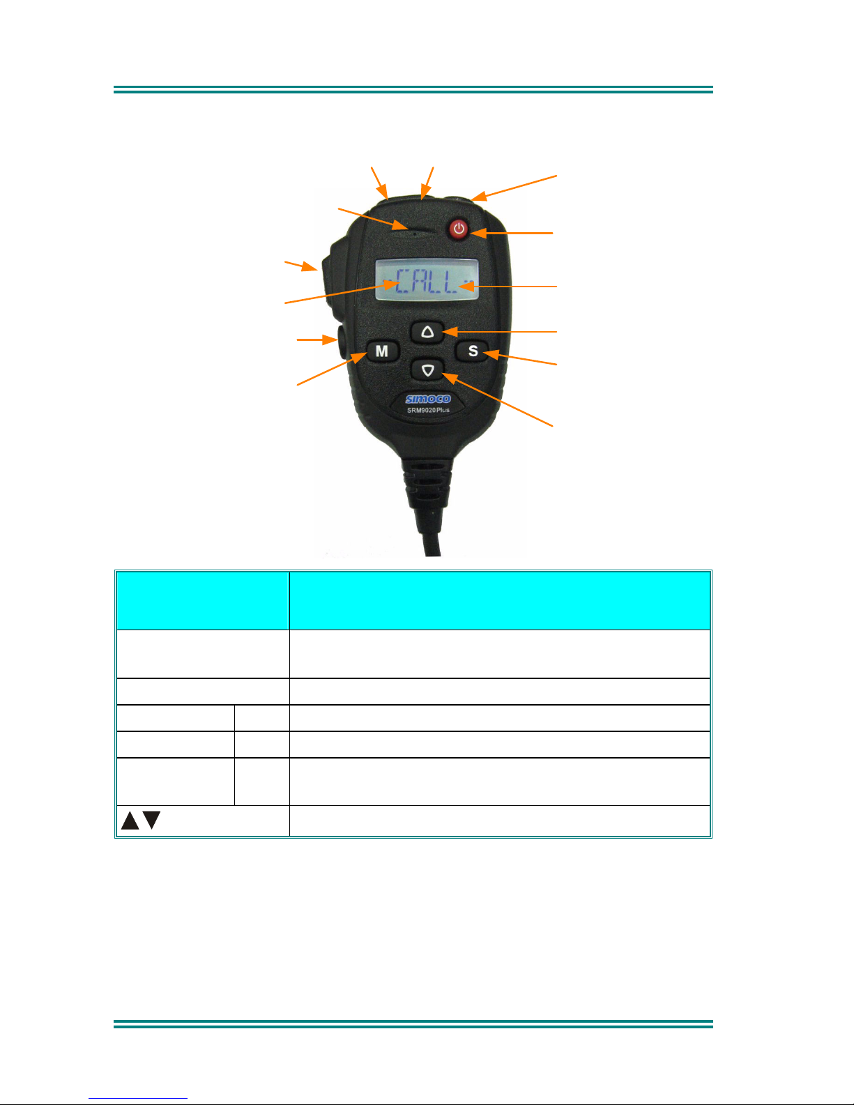
2. FRONT PANEL CONTROLS
Volume Up
Volume Down
On/Off
Icons
Scroll Up
Scroll Down
F4 - Scan On/Off
or Send Selcall
F2 - Function
F3 - Return to Menu
F1 - Change Menu
Display
PTT
Microphone
BUTTON/
CONTROL
FUNCTION
On/Off Push and hold for 1 second to switch the radio On
or Off.
PTT/Pressel
Press-to-Talk switch.
M (Menu) F1
Move between Menu Screens.
F3
Used to return to the Main Menu Screen.
S
(Select)
F4
Used to make a call to the displayed identity, or
activate Scanning.
Scroll up and down through a list within a Menu.
The four programmable buttons, F1 to F4, can be programmed, using the FPP
Programmer, to perform different functions. If the default settings, described
above, are changed, alternative means should be provided to perform their
original functions.
Page 9
SRM9020plus ~ PMR Operating Instructions
© Comgroup Australia 2010 Page 3 TNM-U-E-0086 Issue 1.0a
3. FUNCTIONS AND FACILITIES
3.1 D
ISPLAY AND ICONS
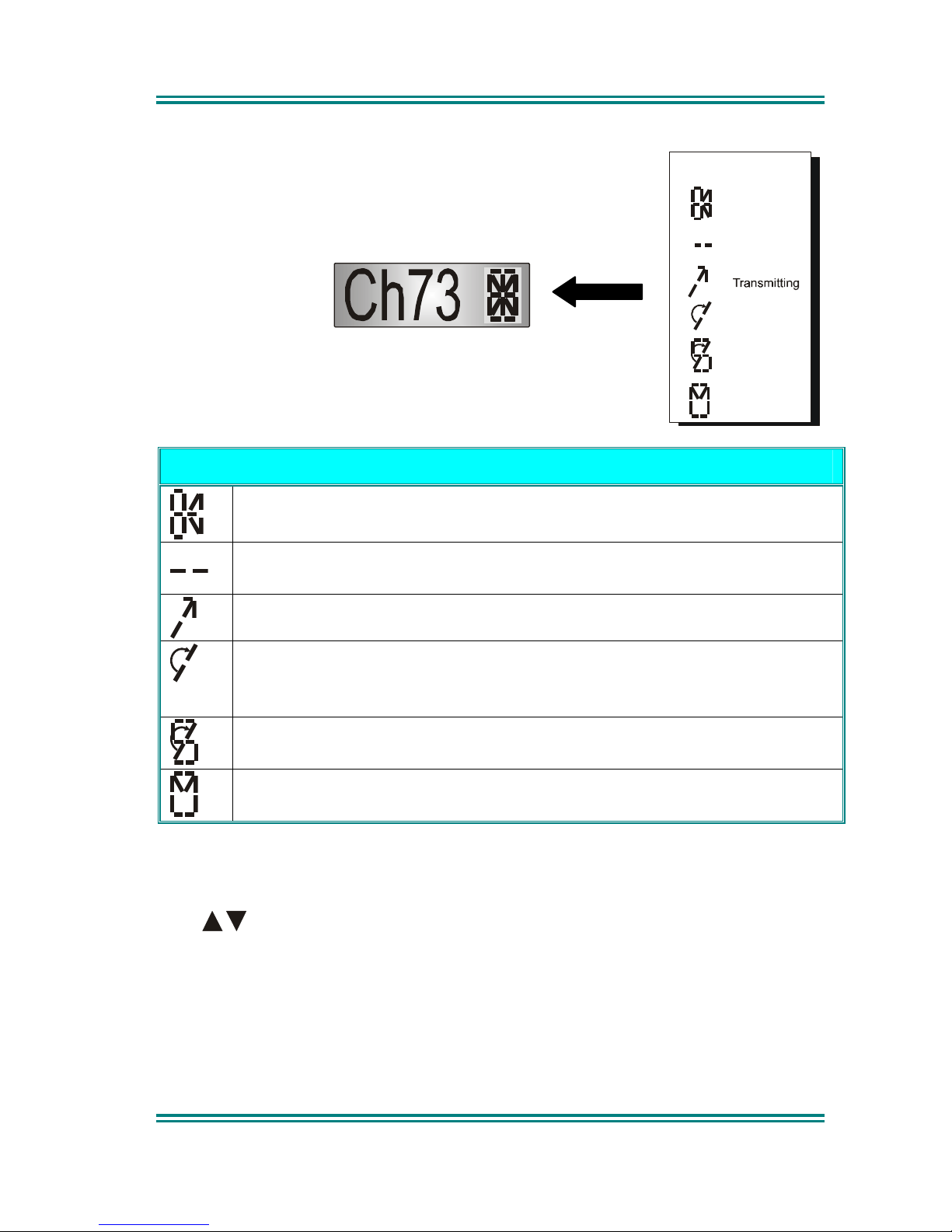
The display shows text information relevant to the
selected Menu Screen.
The Name field (e.g. Ch73) shows the selected entry from
the current screen (e.g. from the Channel List).
Several Icons can be individually displayed as shown
below:
ICONS
Valid signal + CTCSS (and Selcall) is being received.
Audio can be heard from the loudspeaker.
Invalid signal. Carrier with incorrect CTCSS (and/or Selcall) is
being received.
This symbol indicates that the radio is transmitting.
The rotating icon indicates that the radio is searching for a
channel, (e.g. while Voting). The symbol disappears when
stopped on a channel.
Scanning indicator shows that the radio is searching the
channels in the Scan Group.
When not transmitting or receiving, flashes to indicate stored
calls.
The M button scrolls through available Menu options. Where menu selection is
not required, this button can be reprogrammed to perform other functions in this
screen.
The
buttons scroll up and down through the available selections within a
Menu Screen.
The
F1, F2, F4
and F4 buttons are programmable function buttons, in this
screen.
If SELCALL is used, the
F3
button will send the Channel-Encode selcall (with
Current Phonebook Entry and/or Saved Status Value).
Searching
Invalid
Signal
Valid Signal
Icons
Scanning
Stored Call
Page 10
SRM9020plus ~ PMR Operating Instructions
© Comgroup Australia 2010 Page 24 TNM-U-E-0086 Issue 1.0a
3.2 S
WITCH-ON/SWITCH-OFF
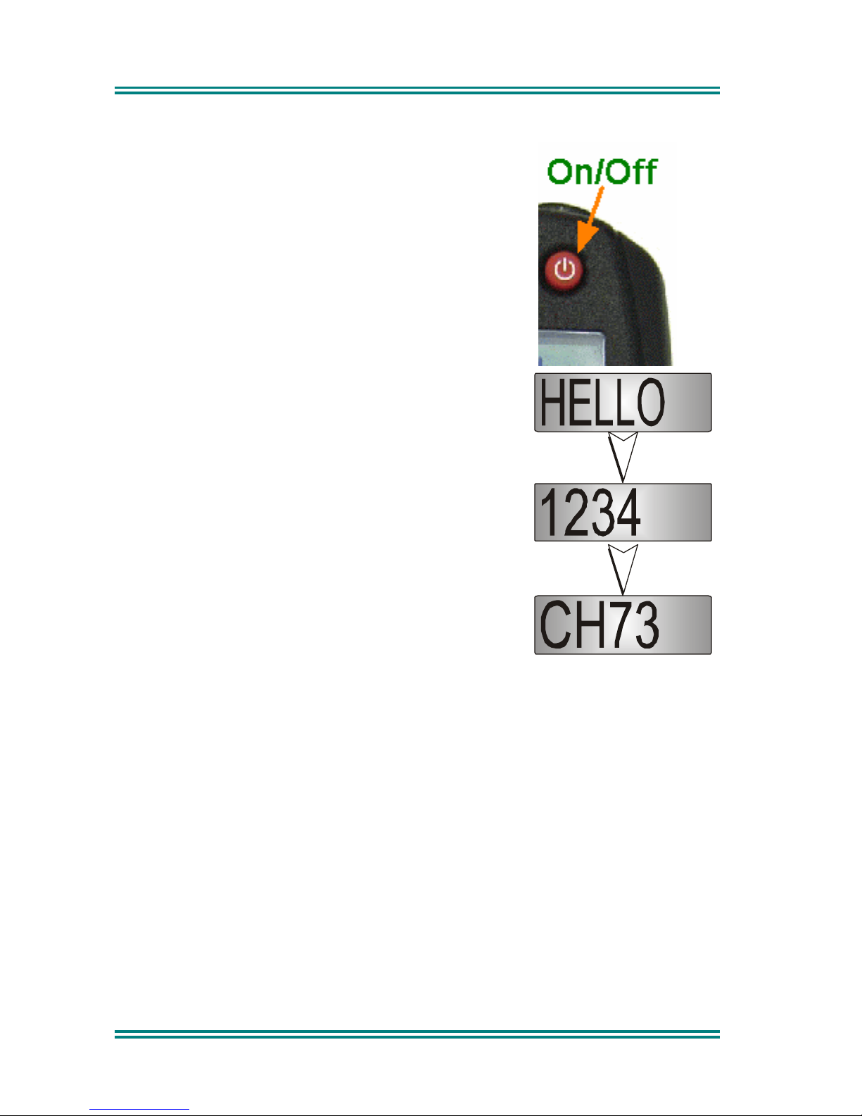
Press and hold down the On/Off button for
approximately 2 seconds to switch the radio ON.
The display will illuminate and briefly show an
'Opening Message’ (arranged by your dealer) and the
Selcall Identity of the radio (if used).
After a brief time the display will show the selected
channel, at which time the radio is ready for use.
Pressing and holding the On/Off button for
approximately 2 seconds will switch the radio Off.
If the radio Inactivity Timer is enabled, the radio will
automatically turn Off after several hours of inactivity
(i.e. no buttons pressed). The radio will emit warning
beeps for 10 seconds prior to switching off. Pressing
any button will reset this timer.
The radio can also be set up to switch on
automatically with the Vehicle Ignition whenever the
vehicle is started.
Page 11
SRM9020plus ~ PMR Operating Instructions
© Comgroup Australia 2010 Page 5 TNM-U-E-0086 Issue 1.0a
3.3 V
OLUME ADJUSTMENT
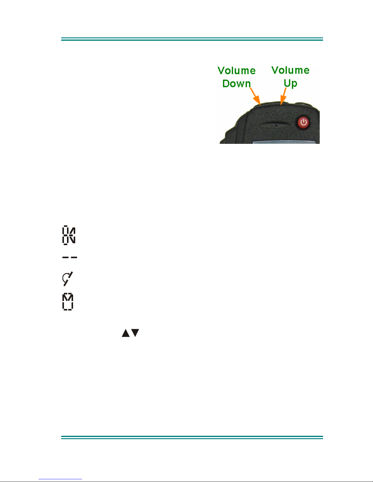
The Volume Up/Down buttons set the
speech level at the loudspeaker.
Use the Up/Down buttons to set the volume
of the received signal to the required level.
When there is no signal a beep will be emitted at each button press to indicate
the volume level. During a call the beeps are omitted.
Note: The radio may be programmed so that the volume cannot be turned
off completely.
3.4 R
ECEIVING
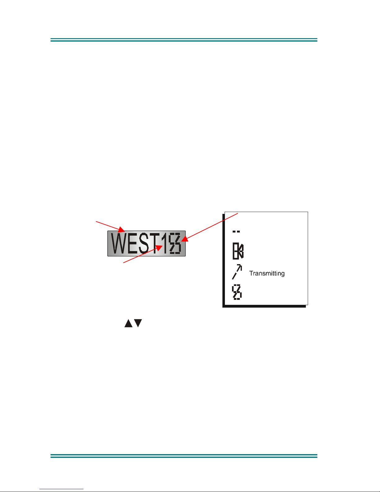
The radio will listen on the displayed Channel. Typical Icons are:
Indicates that a valid signal is present and can be heard from the
loudspeaker.
Indicates that a signal with invalid CTCSS (or Selcall) is present and
that the speaker is muted.
The rotating bar indicates that the radio is searching the displayed
Group.
Displayed when the radio is not receiving and an entry exists in the
Stored Calls Screen.
Changing channels can be achieved by the following:
• Pressing the
buttons.
• Pressing a Go-to-Channel Function Button, refer to Section 7.10.
Note: If the displayed channel is a Vote Group, the Group name is displayed
with a rotating bar icon (when the radio is searching). When stopped
on a channel the Rotating Arrow disappears and the selected Channel
Name replaces the Group name.
Page 12

SRM9020plus ~ PMR Operating Instructions
© Comgroup Australia 2010 Page 24 TNM-U-E-0086 Issue 1.0a
3.5 T
RANSMITTING
To avoid interfering with other users of the channel, listen first to ensure no
transmissions are occurring. Make sure the busy Icon is not shown.
Remove the microphone from its cradle.
Hold the microphone a few centimetres from the mouth, press the “Press-toTalk” (PTT) button. Speak clearly across the face of the microphone in a
normal conversational manner.
In most systems it is important to wait a short time between pressing the PTT
button and commencing to speak. This ensures that the path is properly
established and avoids lost or distorted speech.
Use the correct operating procedure and keep transmissions short. Release
the PTT button as soon as the message is finished.
Notes:
1 A channel may be programmed as Receive-
only or Transmit Inhibit
which can disallow PTT. A continuous tone will be heard if PTT is
attempted.
2 A Transmit Limit Timer may be setup that limits a single
continuous transmission. The last 10 seconds before the timer
expires may be accompanied by warning tones.
3 The radio may be programmed to send a Selcall (ANI) when the
PTT is pressed or released. This may introduce a short delay
before the microphone is enabled or after PTT is released.
Page 13

SRM9020plus ~ PMR Operating Instructions
© Comgroup Australia 2010 Page 7 TNM-U-E-0086 Issue 1.0a
3.6 SELCALL F
UNCTIONS
3.6.1 Receiving a Selcall
A number of different options can be set up by your dealer to sound various
alert tones when a selcall is received. Consult your dealer for a detailed
explanation of your radios set up.
Generally, removing the microphone form its cradle or pressing the PTT will
stop any alerts and answer a received call.
3.6.2 Sending a Selcall
Refer to Phonebook Screen (Section 5.2) and Status Screen (Section 5.3) for
methods of sending a Selcall.
3.6.3 Other Selcall Functions
The SRM9020plus has several other functions that affect how the radio
operates with received signals or selcalls. These functions can be assigned to
buttons in the Main Channel Screen.
Monitor (refer to Section 7.1).
Reset (refer to Section 7.3).
Transpond Enable (refer to Section 7.6).
Send-2 (refer to Section 7.5).
Special Encodes (refer to Section 7.5).
Page 14
SRM9020plus ~ PMR Operating Instructions
© Comgroup Australia 2010 Page 24 TNM-U-E-0086 Issue 1.0a
3.7 S
CAN FUNCTIONS
Scanning consists of sequentially searching up to 15 channels for a valid
signal (RF+CTCSS tone). When found, the radio will stop on that channel until
the signal disappears again.
If a Priority Channel is assigned, the radio will interleave a check of this
channel between each normal channel check. The radio may also check the
Priority Channel every few seconds while stopped on a channel. If a signal is
found on the Priority Channel then the radio will switch to that channel
immediately.
If programmed, the Priority Channel is automatically selected when the
Microphone is removed from cradle.
If scanning is enabled on your radio, press the S button from the Main Channel
Screen to enter Scan Mode, or select a channel that has been programmed as
a scan channel..
3.7.1 Scan Screen
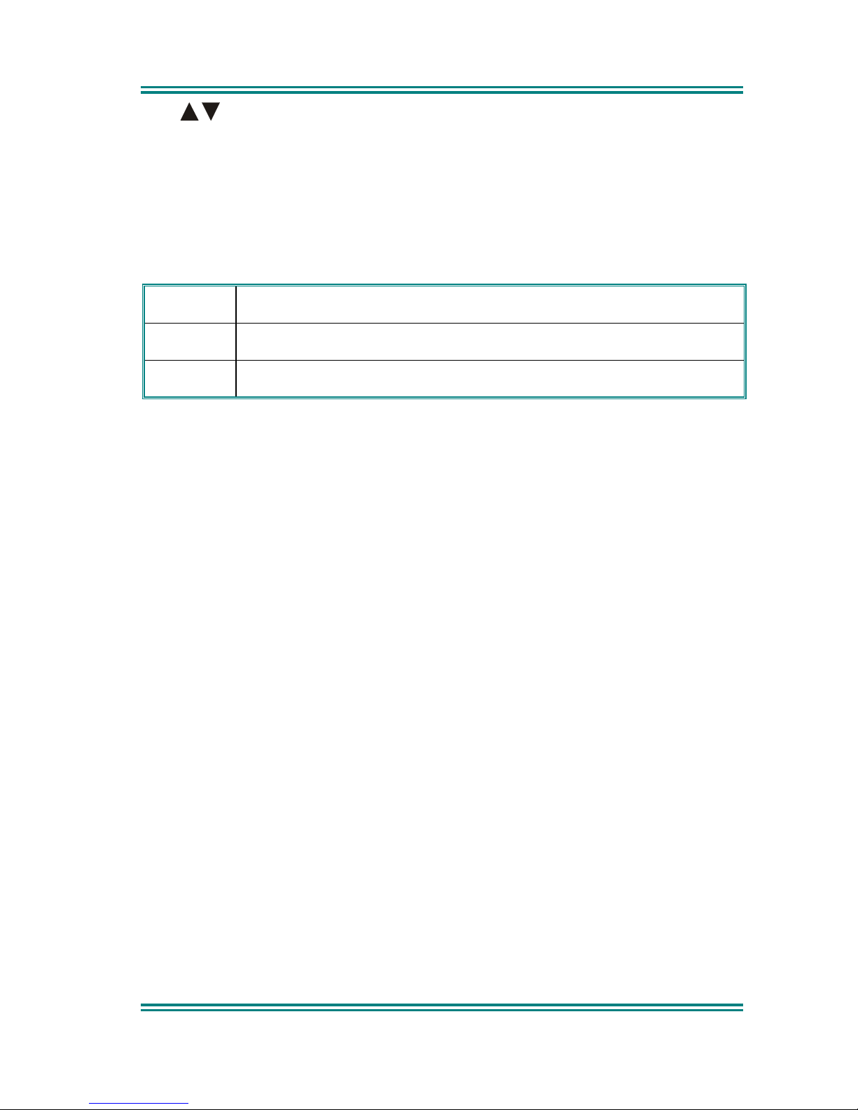
The display shows the name of the current Scan-Group (e.g. “West”), which can
be changed using the buttons. The Scan-Group Number is shown next to
the Icon (e.g. 1) if it is a User Scan-Group, or blank for Fixed Scan-Groups.
(User Scan Groups can be edited by the User).
The Scan Screen does not time-out.
Press the S button to exit to the Main Channel screen.
Whilst listening on the channel, the User may PTT on that channel. After the
signal disappears, or the Microphone is placed back on the Cradle, the radio
will remain listening on the channel for a short time before resuming scanning.
If the radio is not stopped on a channel, and no Priority channel is defined,
when the Mic is removed from Cradle, the channel shown on the display prior to
“Scan” being activated is selected.
Scanning channels
in selected Group
Receiving
Busy
General Icons
Group Name (4 Characters)
User Group Number
Page 15
SRM9020plus ~ PMR Operating Instructions
© Comgroup Australia 2010 Page 9 TNM-U-E-0086 Issue 1.0a
The
buttons allow access to the other screens (not Main Channel
Screen). When these other menus time-out, the display returns to the Scan
Screen.
The Radio may be programmed so that the Microphone needs to be on-cradle
for the radio to scan. If the Microphone is left off-cradle for too long then the
radio will sound a continuous alert tone until it is replaced.
In the Scan Screen the function buttons are assigned as follows.
M
Go to other menus.
F3
Skip channel (only while receiving a signal).
S
Exit scanning.
The
F3
button temporarily deletes (skips) the channel from the Scan-Group.
Skip is only active when stopped on a channel and the Microphone is on-cradle.
Skipped channels are restored when a different Scan Group is selected or if
Scan is exited. The Priority Channel cannot be skipped.
Page 16

SRM9020plus ~ PMR Operating Instructions
© Comgroup Australia 2010 Page 24 TNM-U-E-0086 Issue 1.0a
3.8 MUTE L
EVEL SETTING
The Mute Adjust Screen is accessed from the Setup menu, or (when assigned)
by means of a programmed function button.
When the Mute Adjust Screen is selected the
buttons allow the Radio
Mute level to be adjusted. The level is stored when the Screen is exited via the
S
button, or times-out.
3.9 E
XTERNAL ALERT
Provision is made to connect an external alerting device to the rear of the radio.
The external alert may be activated when a selcall is received (and cancelled by
a timeout, user intervention or receiving a different selcall).
This function is enabled by software programming. When enabled, the External
Alert may be switched On or Off using a Function button.
Page 17

SRM9020plus ~ PMR Operating Instructions
© Comgroup Australia 2010 Page 11 TNM-U-E-0086 Issue 1.0a
4. MENU SYSTEM
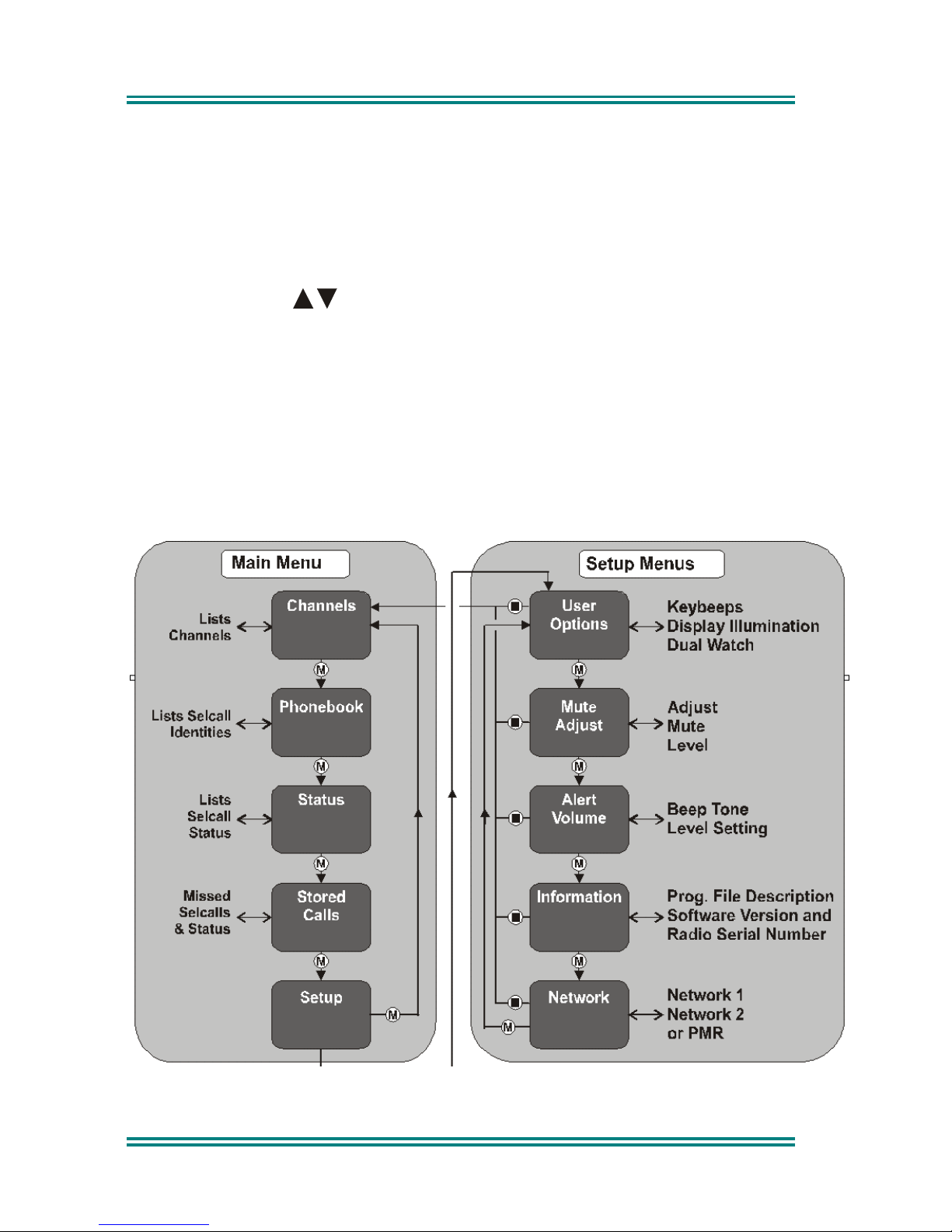
The SRM9020plus radio software uses a programmed Menu structure to enable
the operator to access all of the radio options. The structure of the menu
(comprising up to eleven screens) can be programmed to meet the specific
needs of individual customers.
The diagram on the following page illustrates the default menu structure for
which the radio is programmed at manufacture.
Any or all of the Screens can be programmed for access with the following
proviso.
• The Channel Screen is always programmed in and is the default Screen
displayed.
• The Main Menu provides access to the usual Screens required to operate
the radio.
• The Setup Sub-Menus provide access to the radio setup parameters.
• When options are placed in a Setup sub-menu, Setup should be offered
as a sub menu in the Main Menu selection.
• Both the Main Menu and the Setup submenus can each hold up to ten
Screens.
Page 18
SRM9020plus ~ PMR Operating Instructions
© Comgroup Australia 2010 Page 24 TNM-U-E-0086 Issue 1.0a
4.1 M
ENU NAVIGATION
Navigation
Buttons
M
Move through the available Main Screens
S
Select Setup Sub-Menu
Scroll Up/down though Menu Lists
F3
Return to Main Menu Default Channel
This diagram shows a sample of available menu options. The number of
options and order in which they are accessed will vary between individual
installations.
Page 19
SRM9020plus ~ PMR Operating Instructions
© Comgroup Australia 2010 Page 13 TNM-U-E-0086 Issue 1.0a
5. MAIN MENU SCREENS
5.1 C
HANNEL SCREEN
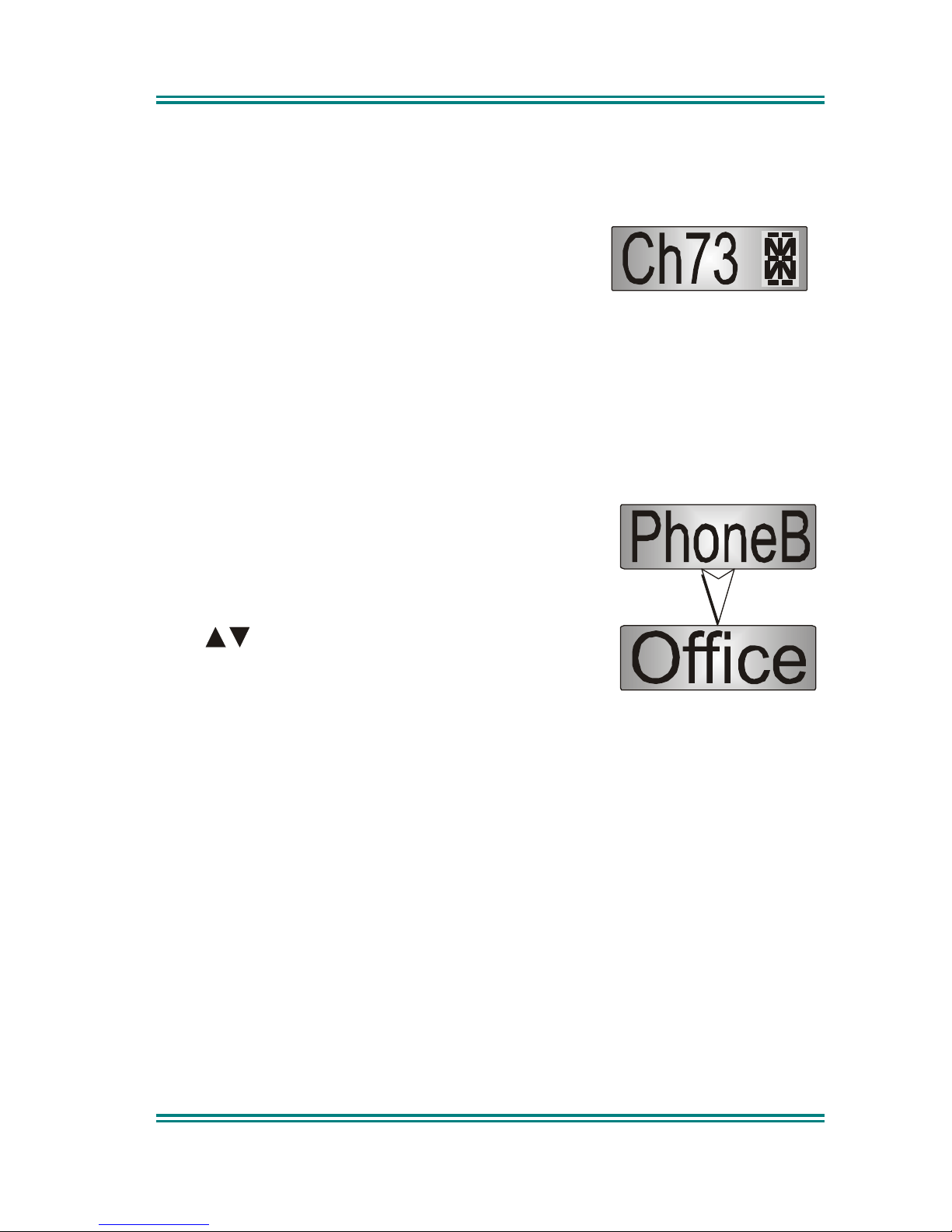
The Channels Screen shows the currently
selected channel and allows it to be changed.
The Name field (e.g. Ch73) shows the selected
entry from the current screen (e.g. from the
Channel List).
5.2 P
HONEBOOK SCREEN
This Screen need only be accessed if Selcall is used. Selcall Identity
information is stored for various users and calls can be placed to them from this
Screen.
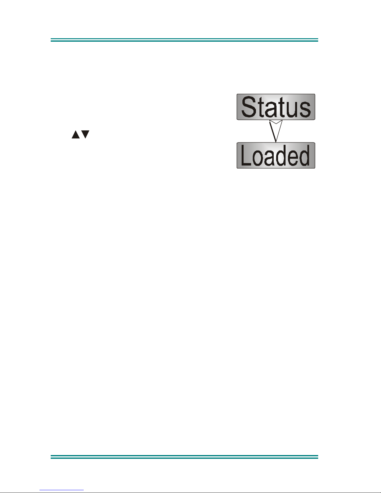
From the Main Channel Menu, press the
M
button
until PhoneB is briefly displayed.
The display will quickly be replaced by the Current-
Phonebook-Entry
The buttons scroll through the Phonebook
entries.
Pressing the S button will place a call to the
displayed identity.
Press the M button to go to other Menu Screens.
Notes:
1 If the Selcall requires a Status to be included then the Saved-
Status-Value will be used.
2 The Identity shown on the display when this Screen is exited
may be referenced from other Menu Screens and is called the
Current-Phonebook-Entry.
Page 20
SRM9020plus ~ PMR Operating Instructions
© Comgroup Australia 2010 Page 24 TNM-U-E-0086 Issue 1.0a
5.3 S
TATUS SCREEN
This Screen need only be accessed if Selcall is used. Selcall Status is stored
here and can be sent from this Screen.
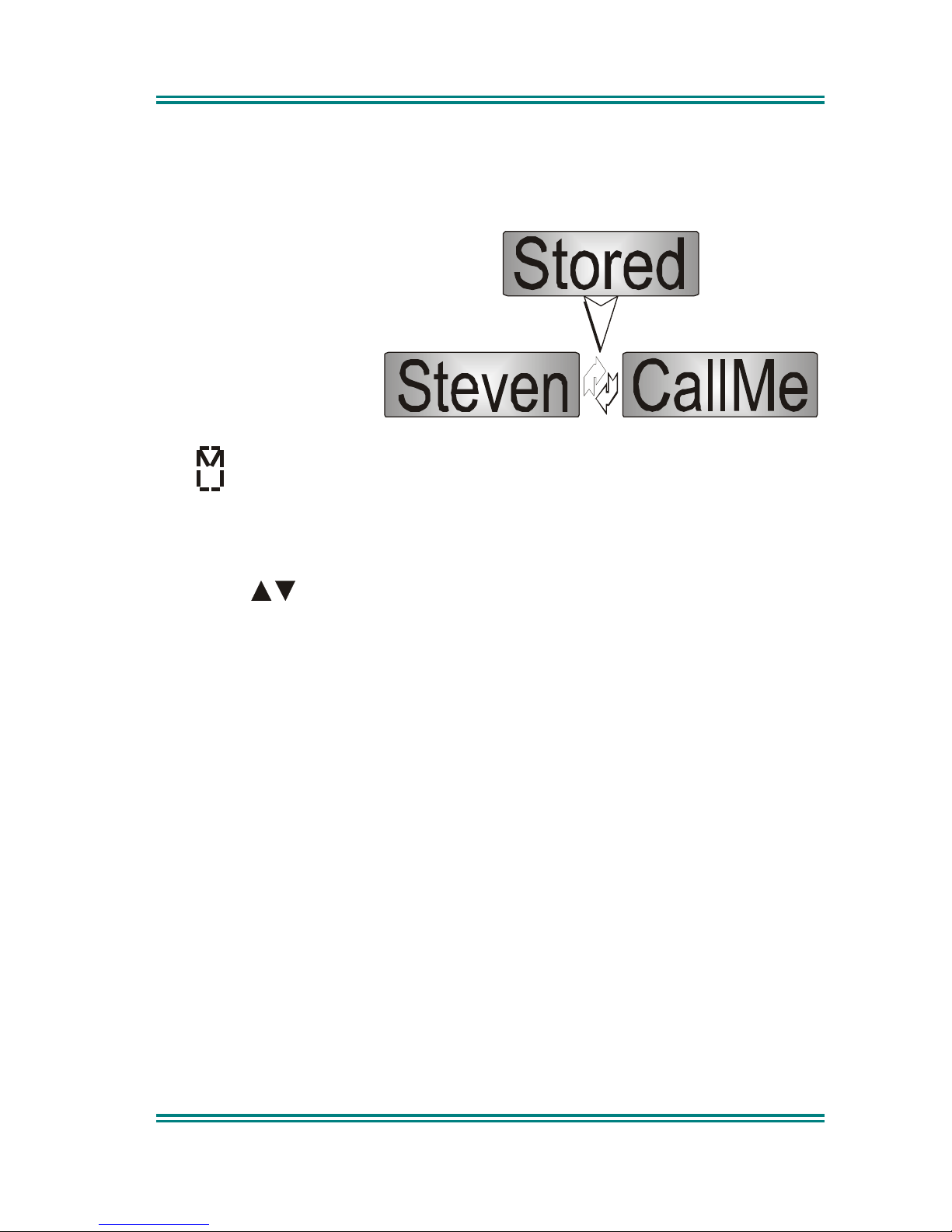
From the Main Channel Menu press the M button
until Status is briefly displayed. The display will
quickly be replaced by the Saved-Status-Value.
The
buttons scroll through the Status List
entries.
Pressing the S button will send the displayed Status
to the Current-Phonebook-Entry.
Press the M button to go to other Menu Screens.
Note: When a Status is sent, it becomes the current Saved-Status-Value
, and
can be used at a later time from other Menu Screens.
Page 21
SRM9020plus ~ PMR Operating Instructions
© Comgroup Australia 2010 Page 15 TNM-U-E-0086 Issue 1.0a
5.4 S
TORED CALLS SCREEN
This screen allows the eight most recent missed Selcalls (calls not answered
before the Alert-tone stops) and received Status Selcalls to be reviewed.
From the Main Channel
Menu, press the M
button until Stored is
displayed. If there are
entries in this menu, the
display will quickly
change to show the
most recently received
calls.
The icon will show in the Main Channel Menu when there is an entry in this
Menu.
The displayed text identifies the caller (e.g. Steven) and, if used, Status text
(e.g. CallMe) is alternately flashed up.
Press the
buttons to scroll through other Stored Calls.
Press the S button to send a return Selcall.
Press the F3 button to return to the Channel Menu without making a call.
Page 22

SRM9020plus ~ PMR Operating Instructions
© Comgroup Australia 2010 Page 24 TNM-U-E-0086 Issue 1.0a
5.5 S
ETUP SCREEN
Use this Screen to access the other Setup submenus.
From the Main Channel Menu, press the M button until
Setup is displayed.
Press the S button to access the submenus.
When a submenu is displayed, press the M button to select other submenus.
Refer to Section 6 for a detailed description of available submenus.
Page 23
SRM9020plus ~ PMR Operating Instructions
© Comgroup Australia 2010 Page 17 TNM-U-E-0086 Issue 1.0a
6. SETUP
The Setup sub-menus allow the operator to modify the operation of some of the
general functions of the radio. The programmer can restructure or restrict
access to any or all of these menus according to specific requirements.
6.1 S
ETUP SUB-MENUS
The default Setup sub-menu structure is shown in the Menu Navigation
diagram. These sub-menu Screens provide access to operator functions as
follows:
User Options
Key beeps, Display Illumination and Dual Watch on/off
selection
Mute Adjust
Mute Level adjustment
Alert Volume
Beep tone level setting (relative to Audio Volume).
Information
Programmer File description, SW version and Serial Number.
Network
Trunk Network-1/2 or Conventional Channel selection.
6.1.1 User Options
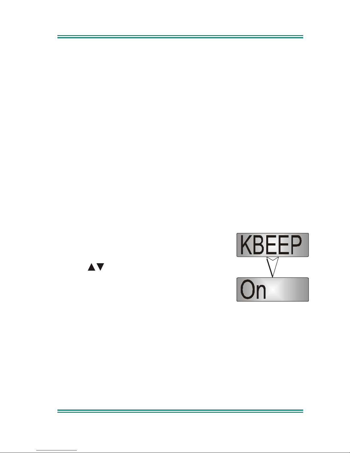
The User Options Screen allows the Keybeeps,
Display Illumination and Dual Watch facilities to be set
On or Off.
Use the buttons to scroll between the different
facilities.
The S button toggles the selection On/Off. The setting
is saved immediately it is changed.
Press the M button to change to the Mute Adjust submenu.
Page 24
SRM9020plus ~ PMR Operating Instructions
© Comgroup Australia 2010 Page 24 TNM-U-E-0086 Issue 1.0a
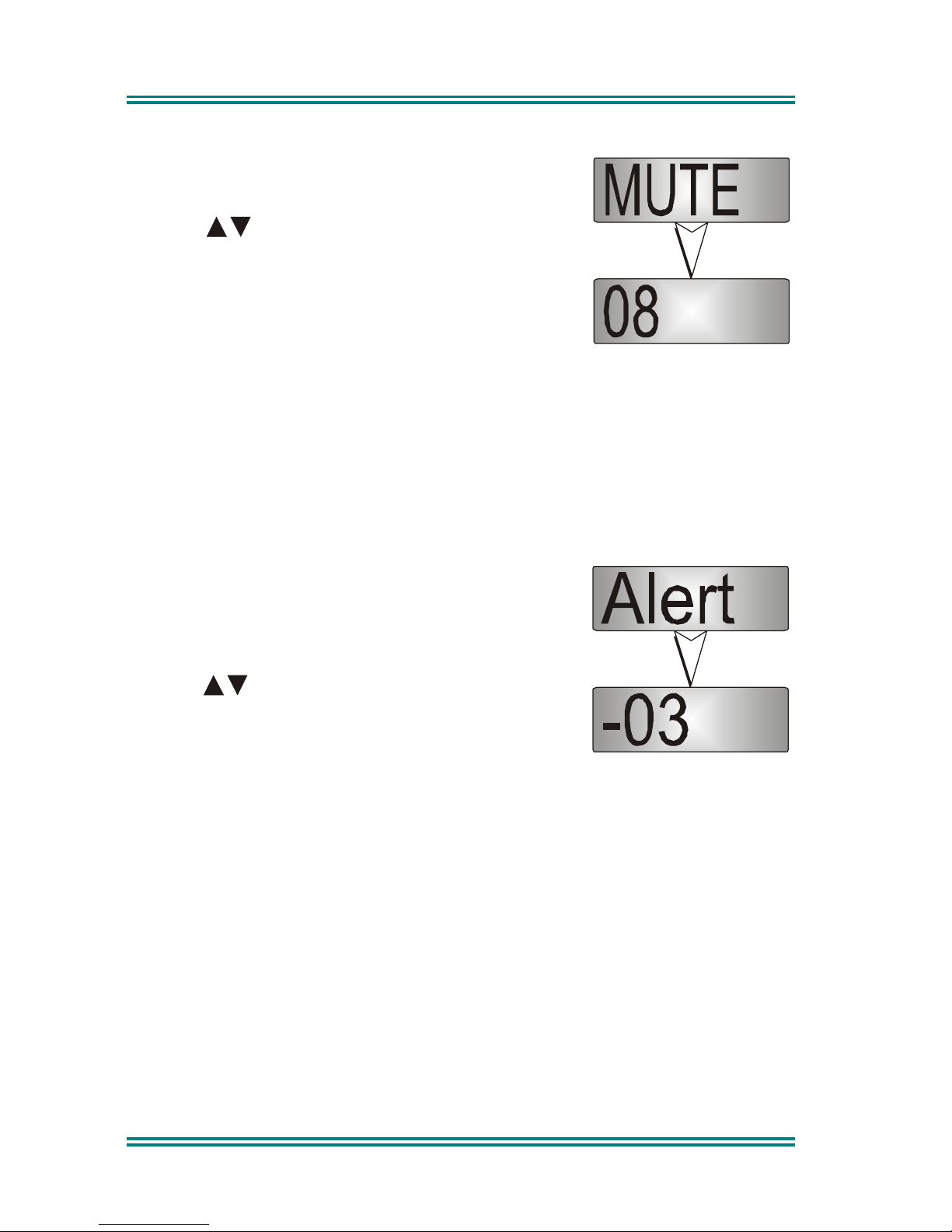
6.1.2 Mute Adjust
Use the Menu Screen to view and change current
Mute setting.
Use the
buttons to change the Mute level.
Use the S button to return to the Channel Screen.
Note : When a Voting channel is selected the
Voting-Mute level is shown, but may not be
changed.
Press the M button to change to the Alert Volume submenu.
6.1.3 Alert Volume
This Screen allows you to set the level of the Alert
Volume Beep Tone in relation to the current Volume
setting. The level can be set in 63 steps over the
range -31 to +31.
Use the
buttons to change the relative alert
level.
Press the S button to accept the setting and go to
the Main Channel Screen.
Press the M button to change to the Information submenu.
Note: A minimum Alert Level may be set to ensure the Alerts can always be
heard from the speaker.
Page 25
SRM9020plus ~ PMR Operating Instructions
© Comgroup Australia 2010 Page 19 TNM-U-E-0086 Issue 1.0a
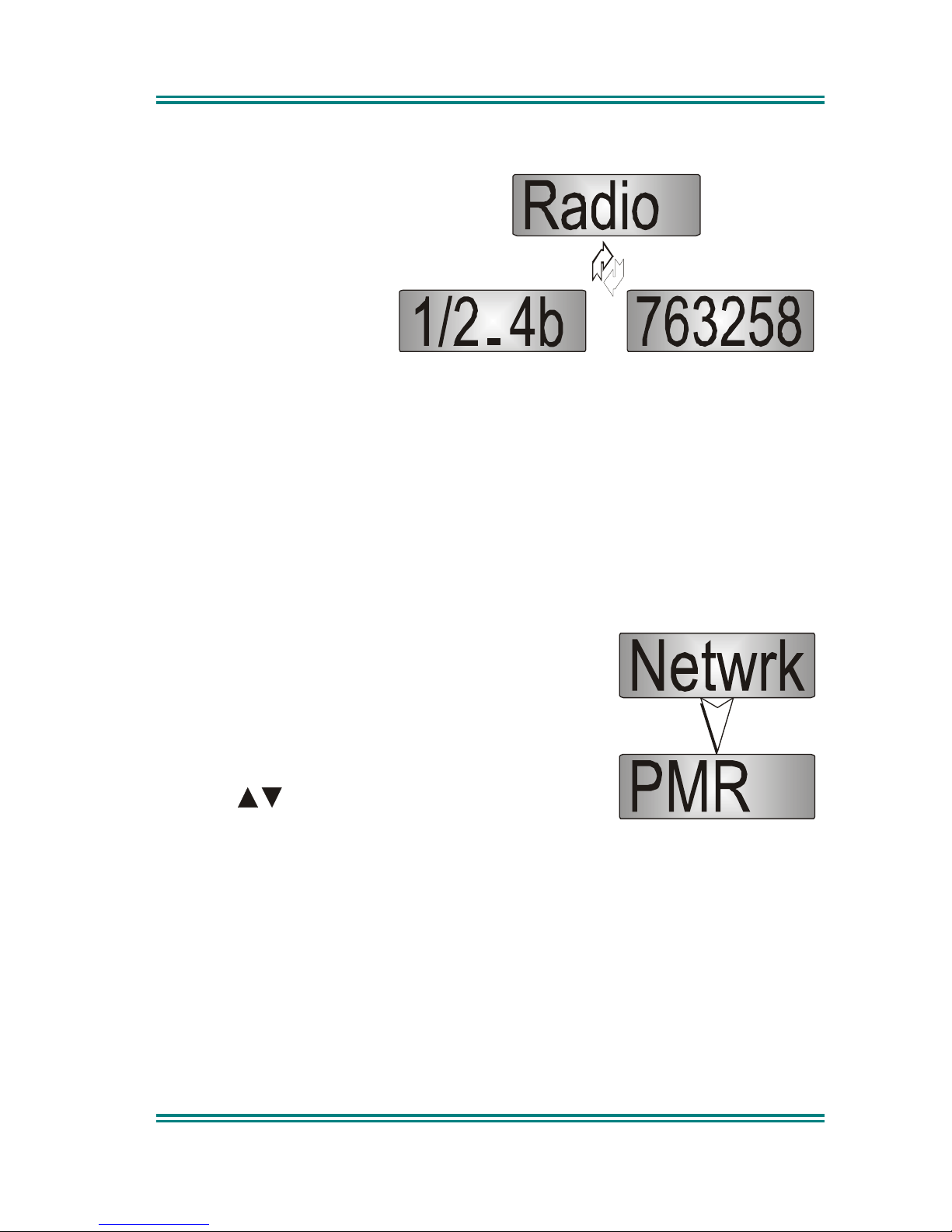
6.1.4 Information
This Screen displays
information that identifies
the Radio Serial Number
Software Version and Own
Identity.
The screen switches
alternately between
Software Version and Own
Identity.
This is a read only Screen, press the S button to go to the Channel Screen.
Press the M button to change to the Network submenu.
6.1.5 Network
The Network Screen allows you to switch operation
between;
• PMR and.
• Trunk Network 1, or 2 (when available).
Use the
buttons to make your selection.
Press the S button to accept that selection and go
to the Channel Screen.
Press the M button to change to the User Options submenu.
Refer to the Trunked Operating Instructions, TNM-U-E-0012, for Trunked
operation.
Page 26

SRM9020plus ~ PMR Operating Instructions
© Comgroup Australia 2010 Page 24 TNM-U-E-0086 Issue 1.0a
7. SPECIAL FUNCTION BUTTONS
This Section lists Functions that may be programmed to the
F2, F3
and
S
(F4)
buttons in the Main Channel screen.
Consult your Simoco Dealer as to which functions have been programmed in
your radio.
7.1 M
ONITOR
Opens/Closes the audio (signalling) mute. Only valid on Non-Community
Repeater type channels and/or Closed Selcall channels without Receiver Lockout programmed.
The display briefly shows ON or OFF when the button is pressed.
7.2 S
QUELCH DEFEAT
Opens/Closes the squelch (carrier) mute.
The display briefly shows ON or OFF when the button is pressed.
7.3 R
ESET
Closes the audio (signalling) mute on closed Selcall Channels.
7.4 S
CAN
Activate Scanning.
7.5 S
END
-2
AND SPECIAL ENCODER 1 TO
8
Sends a specific selcall sequence.
7.6 T
RANSPOND
Enables/Disables Individual Call Acknowledge.
The display briefly shows ON or OFF when the button is pressed.
7.7 CTCSS
Defeats the CTCSS mute on the channel. Only valid on Non-Community
Repeater type channels and/or Open Selcall channels.
The display briefly shows ON or OFF when the button is pressed.
Page 27

SRM9020plus ~ PMR Operating Instructions
© Comgroup Australia 2010 Page 21 TNM-U-E-0086 Issue 1.0a
7.8 M
UTE
Provides direct access to the Mute Setup screen and allows the user to change
the mute level from that screen.
7.9 E
XTERNAL ALERT
Enables/Disables control of External Output via Selcall Decodes.
The display briefly shows ON or OFF when the button is pressed.
7.10 G
OTO CHAN
A, B, C, D
Selects predefined Channel A, B, C or D, and returns on the second press. The
Defined Channel is redefined to the current channel if held for approximately 2
seconds.
The display briefly shows ON or OFF when the button is pressed.
7.11 A
LARM
Puts the mobile into Alarm mode.
7.12 R
EPEATER DEFEAT
Allows the radio to transmit on the reverse frequency on a Repeater Channel.
When the button is pressed again (or the Channel is changed) the transmit
frequency reverts to the original setting.
The display briefly shows ON or OFF when the button is pressed.
7.13 L
OW POWER
Forces the radio to low power. Pressing again puts the radio back to the power
level defined for the current channel. This is not affected by Channel changes.
The display briefly shows ON or OFF when the button is pressed.
7.14 S
CRAMBLER
Toggles the scrambler function for more secure communications..
The display briefly shows ON or OFF when the button is pressed.
Page 28

SRM9020plus ~ PMR Operating Instructions
© Comgroup Australia 2010 Page 24 TNM-U-E-0086 Issue 1.0a
8. OPTIONS
The following options are available, contact your dealer for further information.
8.1 Q
UICK RELEASE TRANSCEIVER KIT
This kit provides a mounting cradle to allow the Transceiver to be quickly
removed without having to undo unnecessary screws.
8.2 M
ICROPHONE/CONTROL HEAD EXTENSION LEAD
This lead allows the Transceiver to be placed up to 4.5 metres from the Control
Head.
8.3 H
ANDSFREE OPTION
This allows a driver to use the radio without having to lift the microphone or
press any buttons.
8.4 T
YPE
1 P
ARALLEL
I/O E
XPANSION OPTION
This option provides eight I/O lines and pre/de-emphasised audio to allow
external interfacing to the radio.
8.5 GPS/ A
UDIO SERIAL INTERFACE OPTION
This provides Global Position reporting for Trunk and PMR applications, as well
as an interface for radio serial control and radio audio.
8.6 C
ROSS-LINKED CABLE
This is used with various applications to cross-connect or interconnect
Transceivers or Control Heads.
8.7 600 O
HM INTERFACE OPTION
This provides a balanced 600 Ohm, 2/4 wires audio interface and opto-isolated
E and M lines.
8.8 D
ESK TOP BASE KIT
This provides a housing for the radio and incorporates an 8 Amp Power Supply
Unit and speaker.
Page 29

SRM9020plus ~ PMR Operating Instructions
© Comgroup Australia 2010 Page 23 TNM-U-E-0086 Issue 1.0a
9. TROUBLESHOOTING
If, after reading this guide, you are unable to switch the radio on, check the
following:
• A fuse has not blown.
Your installer should advise you of the location of the two fuses,
• The power supply cables and their connections are secure, and
• The vehicle battery is charged.
If these checks are OK, contact your dealer or Simoco representative for further
advice.
Page 30
SRM9020plus ~ PMR Operating Instructions
© Comgroup Australia 2010 Page 24 TNM-U-E-0086 Issue 1.0a
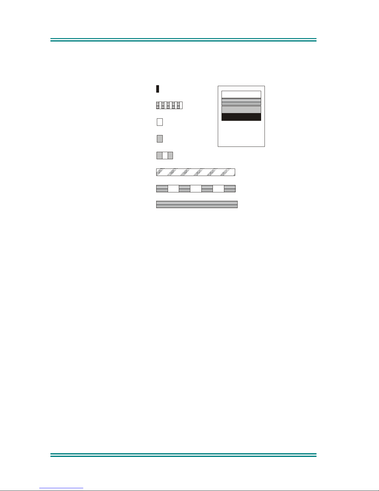
APPENDIX A - ALERT TONES AND MESSAGES
Continuous Alert
Urgent Alert
Off
All durations
indicated in
seconds
440Hz
880Hz
1480Hz
Ring Alert
2 x Bip Alert
Bip Alert
Beep Alert
Error Tone
Key Press
0.1
0.1
0.1/0.1
0.19/0.19
Continuous
0.05/0.05
0.05
Telephone Ring Tone
Page 31

SRM9020plus ~ PMR Operating Instructions
© Comgroup Australia 2010 Page 25 TNM-U-E-0086 Issue 1.0a
APPENDIX B - GLOSSARY
A summary of common radio terms as used in this document, and their
meanings, are given below.
Alert tones
The transceiver emits these tones to indicate an invalid
operator or error.
Cradle
The bracket that holds the microphone when not in use.
Current
Phonebook
Entry
Name that would be shown were the Phonebook screen
shown.
DSP Digital Signal Processor.
DTMF Dual Tone Multi-Frequency (a Signaling method).
Icon A symbol shown on the display.
LCD
Liquid Crystal Display.
MPT1327
The UK Ministry for Post and Telecommunications
specification defining the low level protocol for public
trunking systems.
MPT1343
The UK Ministry for Post and Telecommunications
specification defining the User Interface for radios
operating on MPT1327 public trunking systems.
Network
The trunking infrastructure and all its interconnections.
PMR Private Mobile Radio.
PTT
Press-to-Talk. The PTT button on the microphone must
be depressed for the duration of the transmission.
RF
Radio Frequency.
RSSI Received Signal Strength Indicator.
Saved Status
Value
The last Status that was sent, entered or optionally
received.
SRM Simoco Radio Mobile.
Page 32
© Comgroup Australia 2010
TNM-U-E-0086 Issue 1.0a
Hereby, Comgroup Australia Pty Ltd declares that this
product is in compliance with the essential
requirements and other relevant provisions of
Directive
 Loading...