

Page 1
(SERVOS, WHEREOF ONE MODIFIED,
ARE NOT INCLUDED IN THE KIT)
CONSTRUCTION MANUAL
ALTIMETER
*
1
*
2
*
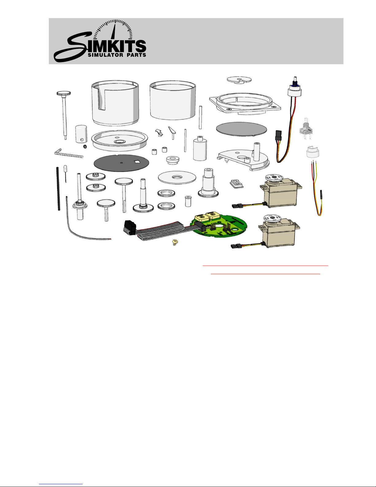
Construction kit “Altimeter” General hints L - Double gearwheel (2 x)
Your kit contains all the necessary Be very careful when using the hobby knife! M - Upper cap rotary encoder
components (except for servomotors) for You can easily hurt yourself when handling N - Propeller shaft
building an “Altimeter”. sharp objects! Take good care of the amount P - Gearwheel with shaft, short
of glue you apply and to which areas you Q - Hollow gearwheel (2 x)
Fine-tuning apply it. Glue for plastics is essentially a R - Gearwheel with shaft, long
The calibration software allows you to solvent. Excessive use can damage the S - Fastening cap 1
accurately adjust the instrument (once exterior of the instrument. T - Fastening cap 2
connected to the Central Control Unit) to U - Bush rotary encoder
the movement of the needle of the chosen Preparations before beginning construction V - Gearwheel shaft
instrument. Check if all components are included. During W - Shaft
packing, the contents of the construction kit X - Indicator 10.000 foot
Difficulty level have been inspected several times. Nothing Z - Indicator 1.000 foot
This product can be constructed without should be missing. Y - Indicator 100 foot
technical expertise. Knowledge of Use the hobby knife to remove any A1 - Front ring
electronics soldering is required. Care and irregularities. Be careful when using the sharp A2 - Front optical
accuracy are of utmost importance. hobby knife! A3 - Upper casing
A4 - Lower casing
What else do you need? Warranty A5 - Light
A normal and a modified servomotor, types Construction kits come without a warranty! A6 - 2-Wire cable
HS300, HS311 or equivalent, are required A7 - Heat shrink sleeve
to make the instrument fully functional (for List of components A8* - Rotary encoder assembly or R1, R2, R3
modifying a servomotor, see the separate A - Metal knob A9 - Self-tapping screw for mounting PCB
manual). This product can be ordered AA - Inbus key R1* - Rotary encoder
separately through the SimKits webshop or B - Bolt (inbus) R2* - Rotary encoder fitting
bought from any retailer of model kits. C - Strain relief R3* - Rotary encoder wire
Additionally you will need some simple D - Printed Circuit Board
tools, such as a small star-shaped E - Lower faceplate
screwdriver, a hobby knife, some pliers, a E1 - Bearing *(A8 or R1, R2, R3 is included)
small hammer, a 1/16” (4 mm) drill, a 0.26” F - Faceplate
(6.5 mm) drill, a soldering iron (suitable for G - Pressure scale
fine electronics), tin solder, insulating H - Outer shaft
adhesive tape, superglue and glue suitable I - Plate
for plastic model kits. J - Central shaft
K - Inner shaft
A3
A4
A1
A2
A5
A7
A6
D
I
C
A
B
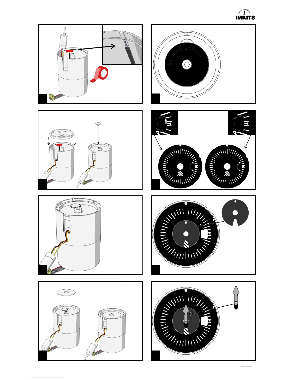
AA
P
R
S
T
M
R1
R2
R3
A8
U
A9
X
Z
Y
W
V
E1
G
Q
Q
L
F
L
K
H
J
N
E
Read this manual carefully
before starting construction
Page 2
S
SIMULATOR PARTS
Page 2
I
3
5
6
7
8
W
U
W
U
M
W
U
A8
4
1
2
Yellow
Red
Black
R1
R3
R2
R2
R3
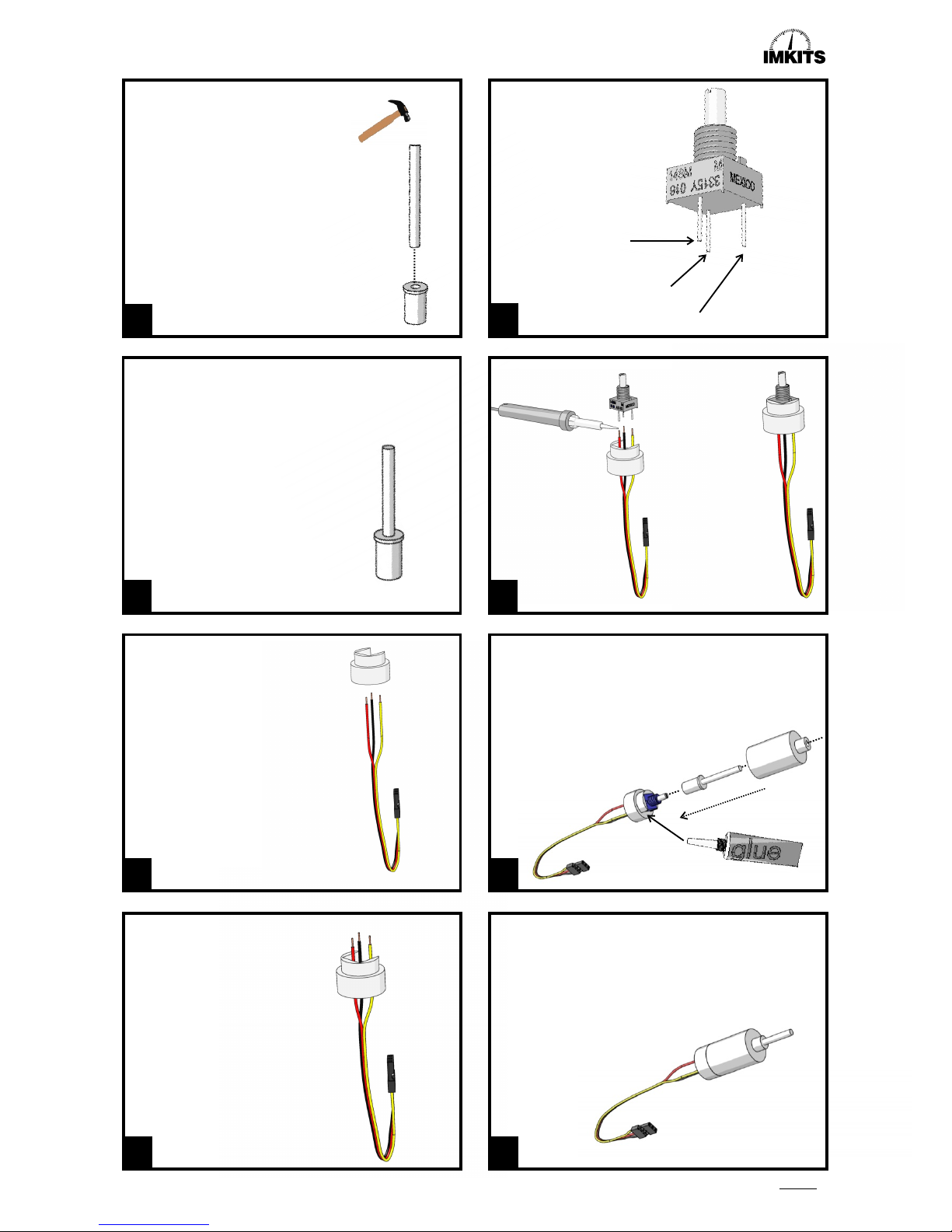
Carefully tap shaft W into cap U until it blocks.
If you find a rotary encoder
assembly A8 inside this
construction kit, you can
continue with drawing 7.
Insert the wires of R3 into
the openings of component R2
as indicated in drawing 4,
respecting the colour indications.
Solder the wires onto
the rotary encoder R1,
as indicated in
drawing 5 and 6.
Place component W/U as assembled in drawing 1 onto t
he rotary encoder shaft. There is a small indentation in
the rotary encoder shaft. The opening of component U
contains a small ridge, which fits exactly into this
indentation. Make sure ridge and
indentation fit completely.
Connect component M to component A8, making sure
no glue comes into contact with the rotary encoder,
with the rotary encoder shaft or with component W/U.
S
SIMULATOR PARTS
Page 2
I I
1
2
3
5
6
7
8
4
Altimeter Construction Manual
Page 3
-Normal SERVO
-Modified SERVO
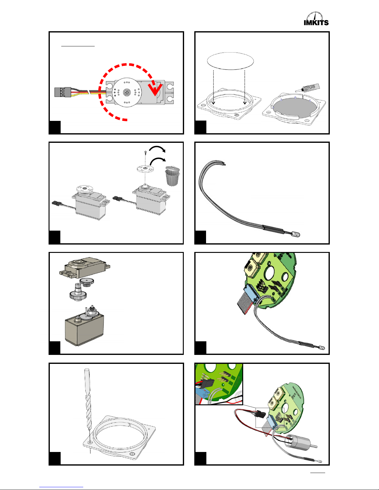
Remove disc and screw.
These parts are no
longer required.
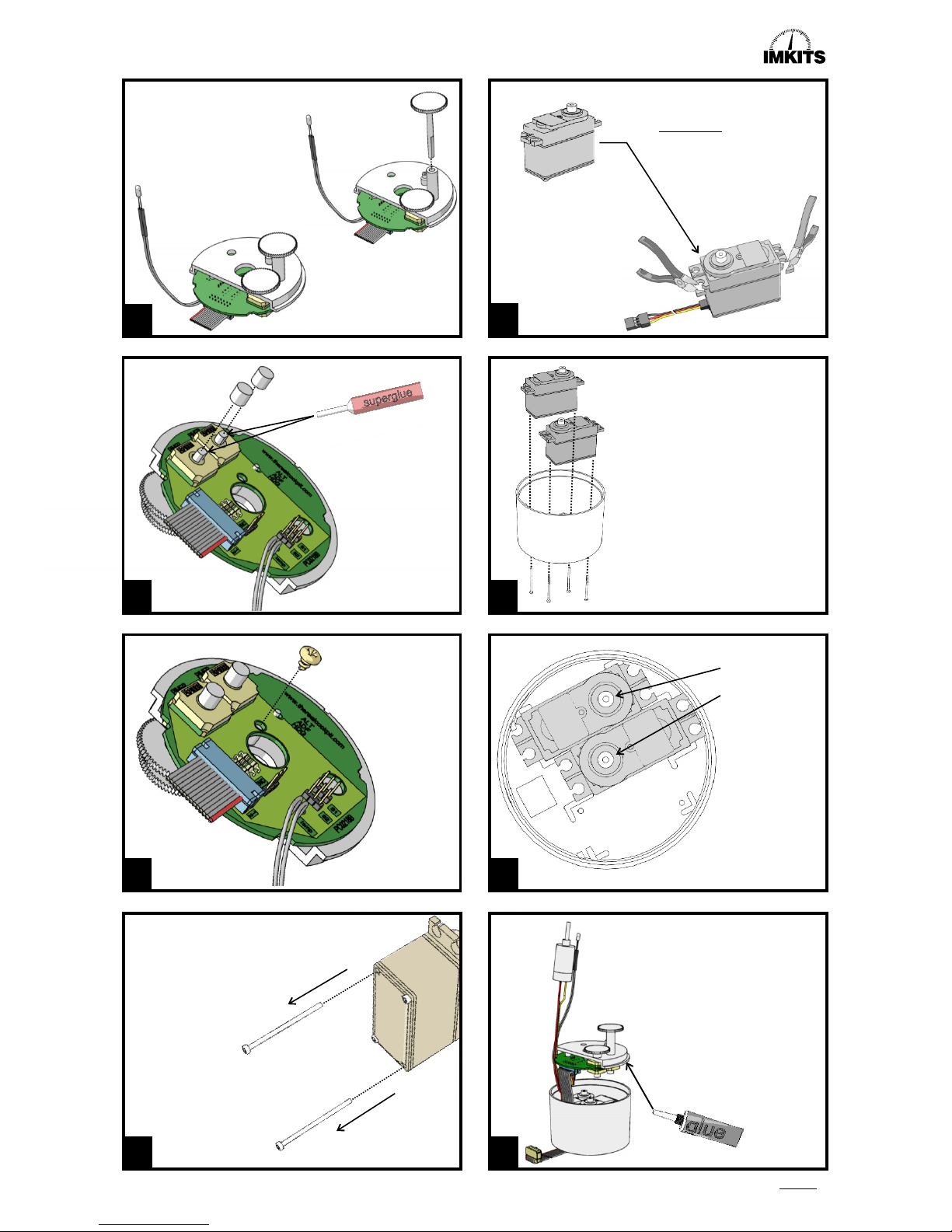
Modify an HS300 or HS311 servo,
or order a modified servo
through the SimKits webshop.
See separate manual for
instructions on modifying a servo.
41
A2
A1
Place optical F into front ring A1
en cement it by sparingly
applying glue to the back f the
front ring, in the edge where
optical and front ring connect.
1
2
0.26"
(6.5 mm.)
A6
A7
A5
A5/A6/A7
D
A8
Connect cord A6 to light A5 by soldering.
Use sleeve A7 to insulate the soldered
connection, but leave roughly 8 mm's
worth of wire free at the base of the light.
The sleeve shrinks when heated.
Connect the wires
to the circuit board.
Polarities are
not important.
Place the rotary encoder assembly's
connector onto the circuit board
as indicated.
Normal SERVO
Twist the servo clockwise by hand until it blocks.
Boor het linker-benedengat
(van voren af gezien) van frontring A1 op, totdat dit een maat
heeft van 0.26" / 6.5 mm.
Page 3
9
10
11
12
13
14
15
16
S
SIMULATOR PARTS
Altimeter Construction Manual
Page 4
46
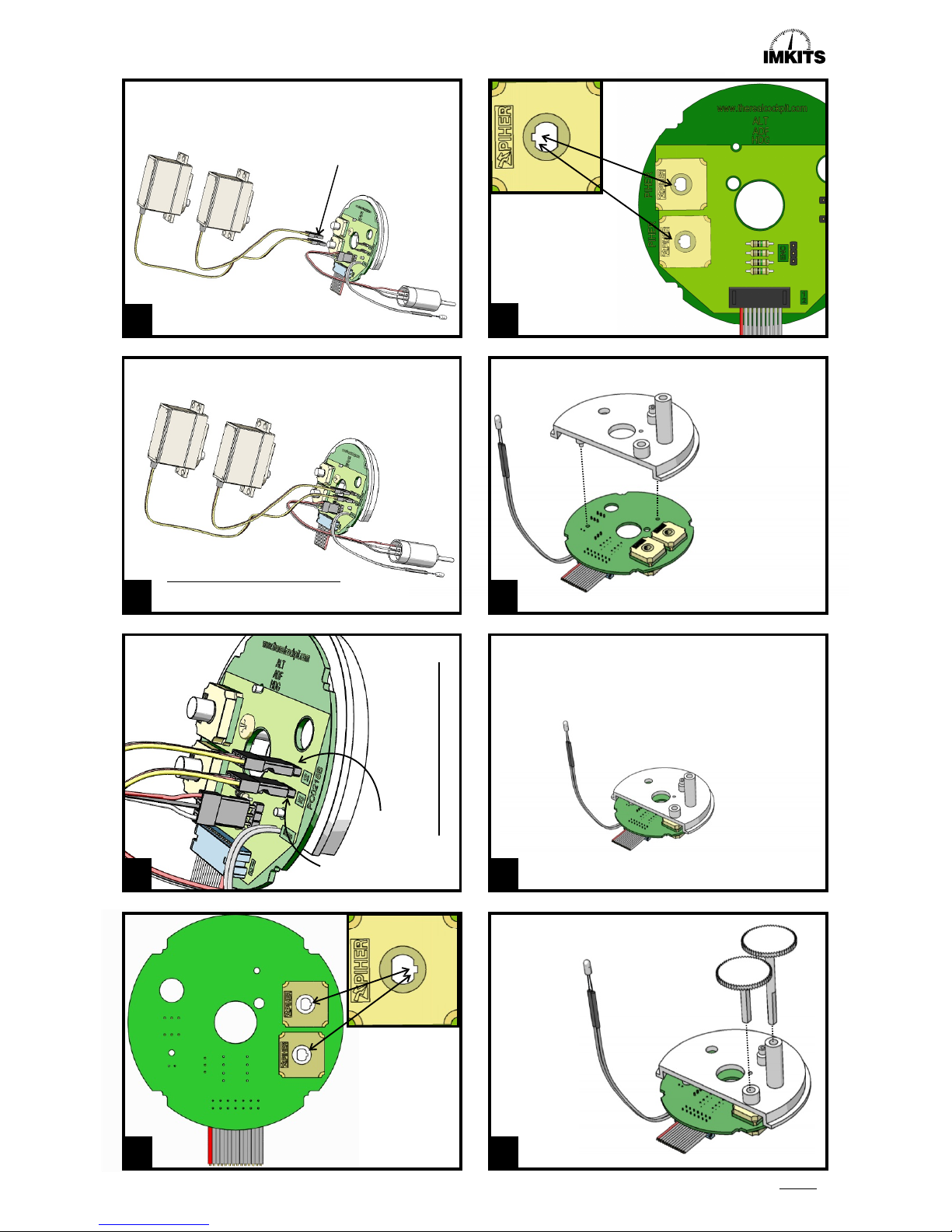
Check if the PIHER
position sensors,
present on both sides
of the circuit board,
are in proper
arrangement, as indicated
in drawings 20 and 21.
Mind the proper
arrangement of
the PIHER
position sensors.
49
50
51
D
I
R
P
Mount plate I onto circuit
board D, using the
positioning notches.
Do not use screws
just yet.
Insert gearwheels
R (longer shaft)
and P (shorter shaft)
into the caps on the plate.
In this drawing the connections between servo and circuit board,
as well as between the rotary encoder and circuit board, have
been omitted for the sake of clarity. For the remainder of
the assembly it is assumed that these are connected
to the circuit board as indicated in drawings 16 through 19.
Modified
servo
Modified
servo
Normal
servo
Normal servo
Page 4
17
18
19
20
21
22
23
24
Modified servo
Normal servo
S
SIMULATOR PARTS
Altimeter Construction Manual
CAUTION! The servos cannot be connected as shown in
picture 17, 18 and 19. The connector of the servos
has to be cut off and the isolation of the wires should be
removed somewhat to enable the wires to be soldered
directly on the PC-Board, due to lack of
space for connectors!
See comment at illustration 17!See comment at illustration 17!
See comment at illustration 17!
Page 5
Cut the ears from the
unmodified servo
as indicate din the drawing.
S
T
A9
!!!!!
Using superglue,
cement caps S and
T onto gearwheel
shafts P and R.
TAKE NOTE: Under
no circumstances
should the PIHER
position sensorrs
come into contact
with glue!
Screw the circuit
board onto the plate
using screw A9
(included).
Unfasten two diagonally placed long screws
from each servo casing as indicated in
the illustration.
R
R
P
P
Make sure the PIHER position
sensors are properly arranged
as indicated in drawings 20
and 21.
Once the shafts of gearwheels
P and R are in position, you can
carefully check whether they
can twist freely.
2X
Page 5
25
26
27
28
29
30
31
32
Normal servo.
Modified servo.
Place the servos into lower casing
A4 as indicated in drawings 30 and 31.
Use the screws you previously
unfastened from the servos (see
drawing 28) to lock them into position.
Take note: do not wind the screws
too tightly!
It's easy to damage the thread
S
SIMULATOR PARTS
Place the plate with circuit board
onto the lower casing, and guide
out the rotary encoder assembly
and the light between the casing
and the circuit board.
Mind the proper positioning of
the plate. Use the positioning
notch to find the right position.
Cement the plate to the lower
casing by applying a few
drops of glue.
Altimeter Construction Manual
Page 6
Page 6
33
34
35
36
37
38
39
40
Lower casing with mounted
plate and circuit board.
Q
K
K
Q
H
G
H
G
G
Q
H
H
Q
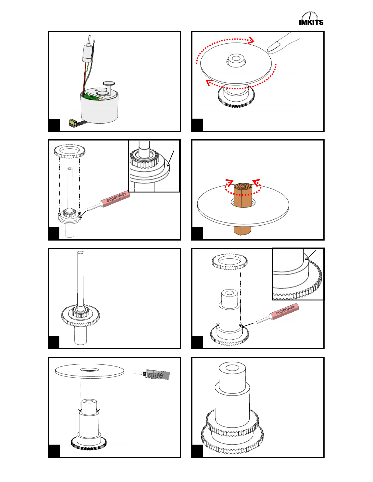
Place gearwheel Q onto inner shaft K
and use superglue to cement the gearwheel.
Apply the glue to component K.
Q+K
Q+H
x
Check if component G can turn
freely on the topmost section of
outer shaft H.
If this is not the case, the central
opening needs to be enlarged
according to instructions in
drawing 38.
Component G
should be able to
move freely when
placed onto
component H.
If this is not the case,
enlarge the central
opening in component
G according to
drawing 38.
Use a rolled-up piece of fine sandpaper to widen the
opening in component G, in case component G does
not turn freely on component H.
Place gearwheel Q onto
component H and cement it.
Apply the glue to
Component H.
S
SIMULATOR PARTS
Altimeter Construction Manual
Page 7
Page 7
41
42
43
44
45
46
47
48
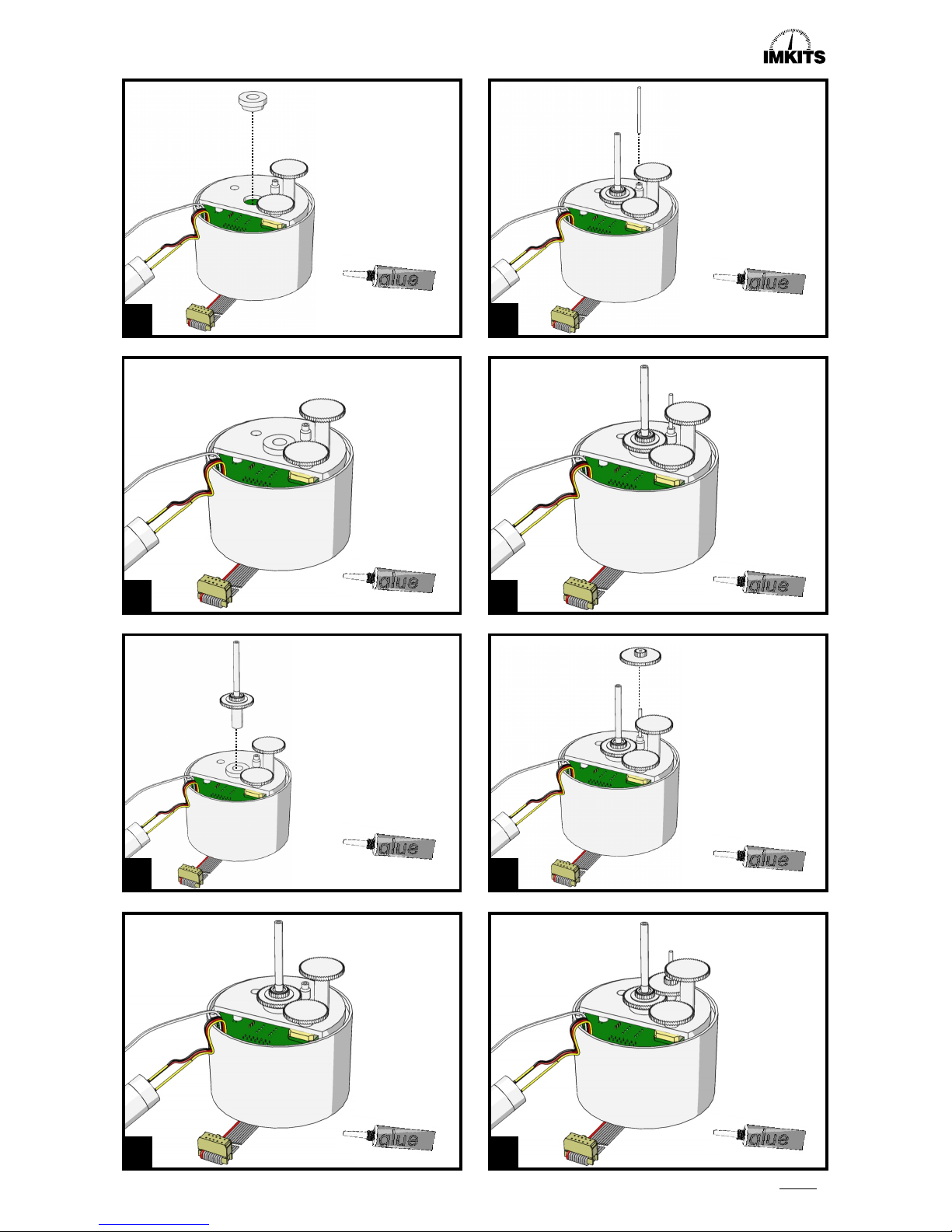
E1
I
K+Q
V
L
A4
Place bearing E1 into
the plate and press it
down. There is no need
to cement bearing E1.
x
x
Insert component K+Q
(inner shaft and gearwheel)
into bearing E1, making sure
the inner shaft aligns with
the modified servo.
x
x
x
x
x
x
Insert gearwheel shaft
V into the indentation on
the plate and press it
down tightly.
Place the first gearwheel
L over the metal
gearwheel shaft.
S
SIMULATOR PARTS
Altimeter Construction Manual
Page 8
Page 8
49
50
51
52
53
54
55
56
J
L
H+Q
A3
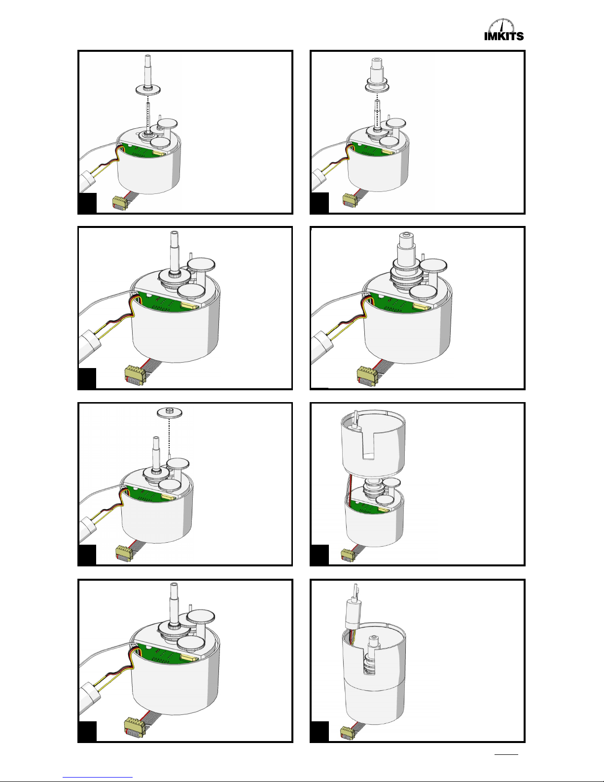
Place central shaft J
over inner shaft K.
Place the second
gearwheel L over the
metal gearwheel shaft.
Place the outer shaft H
over central shaft J,
making sure the
gearwheels connect
properly and smoothly.
Place the upper casing
onto the lower casing,
without using glue.
Guide the rotary encoder and
the light with cord up through
the upper casing.
S
SIMULATOR PARTS
Altimeter Construction Manual
Page 9
II
99
88
77
66
55
44
33
22
00
r
e
t
e
m
i
t
l
A
ALTIMETER
CALIBRATED
TO 20.000FT
I
0
0
0
I
0
I
5
I
020
I02
5
I
0
3
0
I
0
3
5
I0
40
I0
4
5
I050
995
9
9
0
985
9
8
0
975
970
9
6
5
960
9
5
5
9
5
0
9
4
5
2
8
.
I
2
8.
2
2
8
.
3
2
8.
4
2
8
.5
2
8.6
28.
7
28.
8
28
.
9
2
9
.
0
2
9
.
1
2
9
.
2
29
.3
2
9.
4
29
.
5
2
9
.
6
29.
7
29.
8
2
9
.
9
3
0
.0
3
0
.
1
3
0
.
2
3
0
.
3
3
0.
4
3
0
.
5
30
.
6
30
.
7
30.8
3
0
.
9
31
.0
3
1
.
1
3
1
.
2
3
1.3
3
1
.4
3
1
.5
3
1.6
2
8
.
I
2
8
.
2
28.3
2
8
.
4
28
.
5
2
8
.
6
2
8.7
28.8
2
8
.
9
29
.
0
2
9
.
1
2
9.
2
29
.
3
2
9.
4
2
9.
5
2
9
.
6
2
9
.7
2
9
.
8
2
9
.
9
3
0
.0
30.
1
3
0
.2
30
.3
3
0
.
4
3
0
.
5
30
.
6
30.7
3
0
.8
3
0
.9
31.0
3
1.1
3
1.2
31.3
3
1
.4
3
1
.5
3
1
.6
I
9
8
7
6
5
4
3
2
0
r
e
t
e
m
i
t
l
A
II
99
88
77
66
55
44
33
22
00
r
e
t
e
m
i
t
l
A
31.5
31.6
22
I045
I050
22
USA (Inches)
EUROPE (Millibar)
Position the air pressure
scale exactly as indicated in
the illustration. Make sure
the servo remains in the
same exact position as
before!
Position the air pressure
scale G (inches or millibar)
exactly as indicated in the
illustration. Use the
altimeter's faceplate
as an aid, and
permanently place
the faceplate onto
the upper casing
as well. Mind the
proper positioning
by using the
positioning notches.
II
99
88
77
66
55
44
33
22
00
r
e
t
e
m
i
t
l
A
ALTIMETER
CALIBRATED
TO 20.000FT
ALTIMETER
CALIBRATED
TO 20.000FT
Page 9
57
58
59
60
61
62
63
64
E
N
G
X
Z
Mount the light on
the inside of the
upper casing. The
light needs to
protrude 0.1”
(2.5 mm) from
the edge.
Place lower faceplate E onto the upper casing. Then
carefully press propeller shaft N into the shaft's opening in
the unmodified servo.
This needs to be
done with great care!
Now place the
10.000 ft indicator
X as shown in the
illustration and
press it down.
Do not use glue!
Now place the
1.000 ft indicator
Z as shown in the
illustration and
press it down.
Do not use glue!
S
SIMULATOR PARTS
Altimeter Construction Manual
Page 10
II
99
88
77
66
55
44
33
22
00
r
e
t
e
m
i
t
l
A
ALTIMETER
CALIBRATED
TO 20.000FT
Page 10
C
C
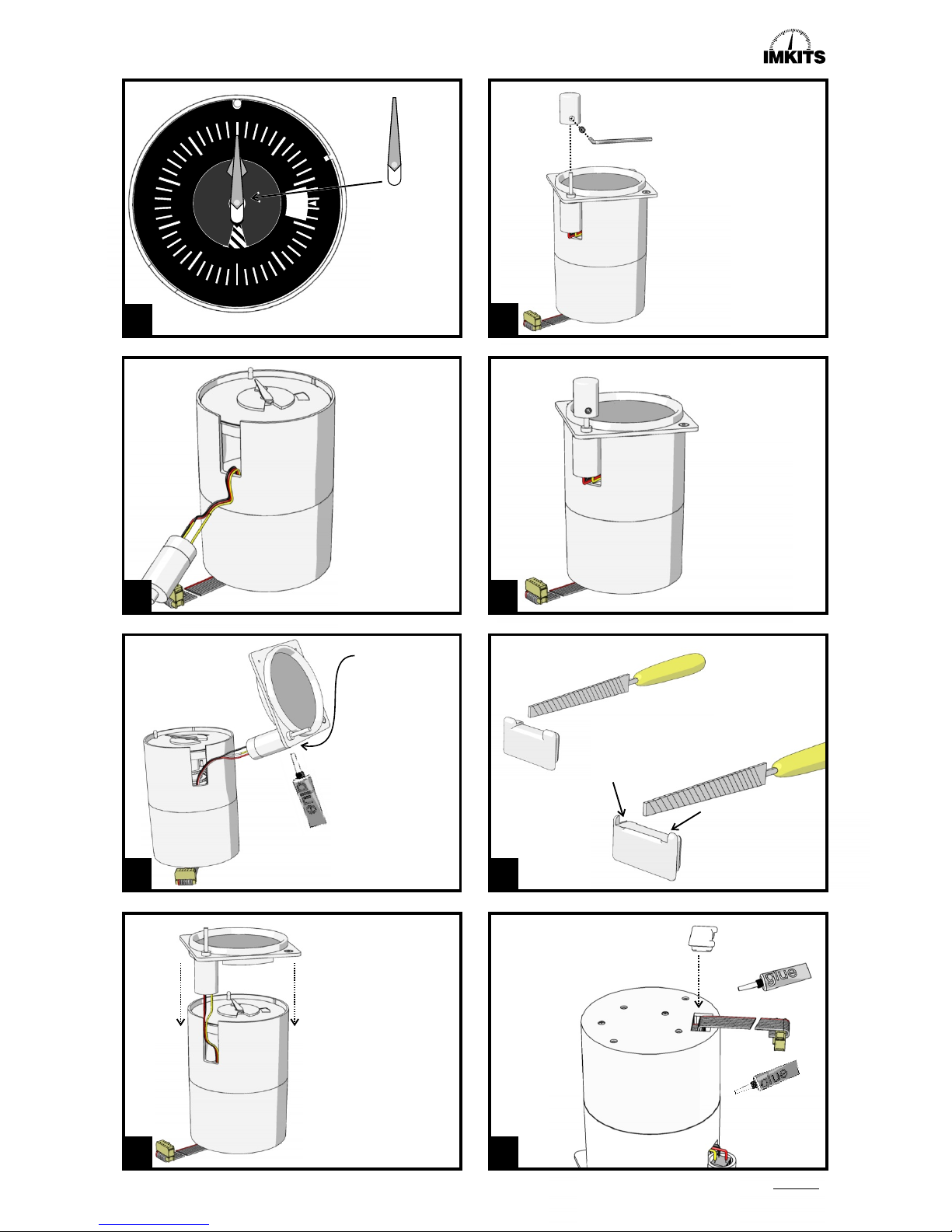
The strain relief needs to be filed
down somewhat to facilitate the
14-pin flatcable.
Fix the flatcable into its
proper position in the
lower casing by using
strain relief C.
Page 10
65
66
67
68
69
70
71
72
Y
A1+A2
A8
A
B
AA
Now place the
100 ft indicator Y
as shown in the
illustration and
press it down.
Do not use glue!
Mount the rotary
encoder assembly
A8 into front
ring A1.
Place front ring A1 onto
the upper casing, without
using glue.
You can now connect the
Altimeter to the Central
Control Unit and test if it
functions properly by
using the calibration
software.
If necessary, temporarily
use some adhesive tape
to keep the components
together.
Fix knob A to the rotary
encoder shaft, using bolt
B and the inbus key.
S
SIMULATOR PARTS
Altimeter Construction Manual
 Loading...