

Page 1
Assisting the automation
industry since 1986
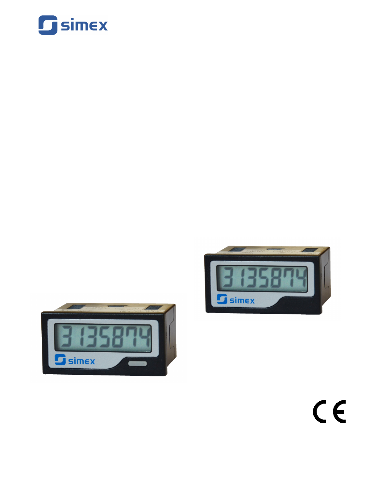
User manual
for electronic counters:
totalizer
SLE-42
timer
STH-42
• Firmware version: from v.1.00
• Type of input: contact / OC or voltage
• Self powered, 3.6V 1/2AA Lithium Battery
Read the user's manual carefully before starting to use the unit or software.
Please keep this manual for future reference.
Producer reserves the right to implement changes without prior notice.
26.10.2011 SLE42_STH42_INSSXEN_v.1.00.002
SLE-42
STH-42
Page 2
User manual for electronic counters SLE-42 and STH-42
CONTENTS
1. BASIC REQUIREMENTS AND USER SAFETY.........................................................................................2
2. GENERAL CHARACTERISTICS................................................................................................................3
3. TECHNICAL DATA......................................................................................................................................4
4. DEVICE INSTALLATION.............................................................................................................................5
4.1. UNPACKING.......................................................................................................................................5
4.2. ASSEMBLY.........................................................................................................................................5
4.3. WIRING AND REAR TERMINALS.....................................................................................................7
4.4. MAINTENANCE..................................................................................................................................8
4.5. BATTERY REPLACEMENT...............................................................................................................8
5. FRONT PANEL DESCRIPTION..................................................................................................................9
6. PRINCIPLE OF OPERATION....................................................................................................................10
Explanation of symbols used in the manual:
- This symbol denotes especially important guidelines concerning the installation and
operation of the device. Not complying with the guidelines denoted by this symbol may
cause an accident, damage or equipment destruction.
IF THE DEVICE IS NOT USED ACCORDING TO THE MANUAL THE USER IS
RESPONSIBLE FOR POSSIBLE DAMAGES.
- This symbol denotes especially important characteristics of the unit.
Read any information regarding this symbol carefully
1. BASIC REQUIREMENTS AND USER SAFETY
-
The manufacturer is not responsible for any damages caused by
inappropriate installation, not maintaining the proper technical condition
and using the unit against its destination .
- Installation should be conducted by qualified personnel. During installation all
available safety requirements should be considered. The fitter is responsible for
executing the installation according to this manual, local safety and EMC
regulations.
- The unit must be properly set-up, according to the application. Incorrect
configuration can cause defective operation, which can lead to unit damage or
an accident.
-
If in the case of a defect of unit operation there is a risk of a serious threat
to the safety of people or property additional, independent systems and
solutions to prevent such a threat must be used.
-
The unit uses dangerous voltage that can cause a lethal accident. The unit
must be switched off and disconnected from the power supply prior to
starting installation of troubleshooting (in the case of malfunction).
- Neighbouring and mating equipment must meet the requirements of appropriate
standards and regulations concerning safety and be equipped with adequate
anti-overvoltage and anti-interference filters.
2
i
Page 3
User manual for electronic counters SLE-42 and STH-42
-
Do not attempt to disassemble, repair or modify the unit yourself. The unit
has no user serviceable parts. Units, in which a defect was stated must be
disconnected and submitted for repairs at an authorized service centre.
- In order to minimize fire or electric shock hazard, the unit must be protected
against atmospheric precipitation and excessive humidity.
- Do not use the unit in areas threatened with excessive shocks, vibrations, dust,
humidity, corrosive gasses and oils.
- Do not use the unit in explosion hazard areas.
- Do not use the unit in areas with significant temperature variations, exposed to
condensation or icing.
- Do not use the unit in areas exposed to direct sunlight.
- Make sure that the ambient temperature (e.g. inside the control box) does not
exceed the recommended values. In such cases forced cooling of the unit must
be considered (e.g. by using a ventilator).
The unit is designed for operation in an industrial environment and must
not be used in a household environment or similar.
2. GENERAL CHARACTERISTICS
The electronic counters are popular, self-powered LCD totalizers (
SLE-42
) or hour
meters (
STH-42
) in a small form. With a panel size of DIN 48 x 24 mm, they are perfect for
limited space installations. They are powered by a replaceable lithium battery that lasts
approximately 7 years, no external power required. They are available in 7 digits with 8 mm
height figures with front reset or remote reset options. Input signal includes dry contact, open
collector, voltage, wide range voltage at maximum count speed up to 30 Hz. The front panel
protection is IP 54 and wiring connection is easily done via the terminal block connector,
making it secure and reliable. CE, UL and RoHS compliant.
3
Page 4

User manual for electronic counters SLE-42 and STH-42
3. TECHNICAL DATA
Power supply voltage 3.6V 1/2AA Lithium Battery (inside), 7 years (replaceable)
Pulse inputs
Dry Contact/OC/Voltage
Wide-Range Voltage
NPN Transistor
Sink current approx. 8 μA
Input levels : L < 0.8V, H: 2 - 30 V
Count speed: max. 30 Hz (
SLE-42
)
Input impedance 300 kΩ
Input levels L: 0 - 10V AC/DC, H: 20 - 250V AC/DC
Count speed: max. 20 Hz (
SLE-42
)
Resolution
1 count per 1/10 hour (
STH-42
)
Reset Remote reset: dry contact/OC/voltage or wide-range voltage
or front panel reset (only
SLE-42
)
Reset pulsewidth 6 ms min.
Display 7 digits, 7-segment LCD, 8 mm
Display range
0 ÷ 9999999 (
SLE-42
); 0.0 ÷ 999999.9 (
STH-42
)
Front panel protection IP 54
Wiring M3 terminal screw
Housing type
Housing dimensions
Panel cut size
Weight
panel
48 x 24 x 39,7 mm
45 x 22,2 mm (+1 mm)
approx. 50 g (battery included)
Operating temperature
Storage temperature
Humidity
-10°C to +55°C (non-freezing)
-20°C to +65°C (non-freezing)
25 to 85% (non-condensing)
Vibration / Shock resistance
Operation:
Storage:
double amplitude 0.3 mm; frequency: 10 - 55 Hz, X, Y, Z Axis
(3 axis) / 100 m/s²
double amplitude 0.75 mm; frequency: 10 - 55 Hz, X, Y, Z Axis
(3 axis) / 300 m/s²
Noise immunity Electrostatic discharge: IEC-61000-4-2 8kV
Electromagnetic field: IEC-61000-4-3 10V/m
EFT/BI/O leads: IEC-61000-4-4 1.0kV
EMC standard EMI: EN50081-2
EMS: EN50082-2
Compliance RoHS ; CE ; UL 863
This is a class A unit. In housing or a similar area it can cause radio
frequency interference. In such cases the user can be requested to use
appropriate preventive measures.
4
Page 5
User manual for electronic counters SLE-42 and STH-42
4. DEVICE INSTALLATION
The unit has been designed and manufactured in a way assuring a high level of user
safety and resistance to interference occurring in a typical industrial environment. In order to
take full advantage of these characteristics installation of the unit must be conducted correctly
and according to the local regulations.
- Read the basic safety requirements on page 2 prior to starting the installation.
- Ensure that the power supply network voltage corresponds to the nominal
voltage stated on the unit’s identification label.
- The load must correspond to the requirements listed in the technical data.
- All installation works must be conducted with a disconnected power supply.
- Protecting the power supply clamps against unauthorized persons must be
taken into consideration.
4.1. UNPACKING
After removing the unit from the protective packaging, check for transportation damage. Any
transportation damage must be immediately reported to the carrier. Also, write down the unit
serial number on the housing and report the damage to the manufacturer.
Attached with the unit please find:
- user’s manual,
- warranty,
- accessories.
4.2. ASSEMBLY
- The unit is designed for mounting indoor inside housings (control panel,
switchboard) assuring appropriate protection against electric impulse waves.
Metal housing must be connected to the grounding in a way complying with the
governing regulations.
- Disconnect the power supply prior to starting assembly.
- Check the correctness of the performed connections prior to switching the unit on.
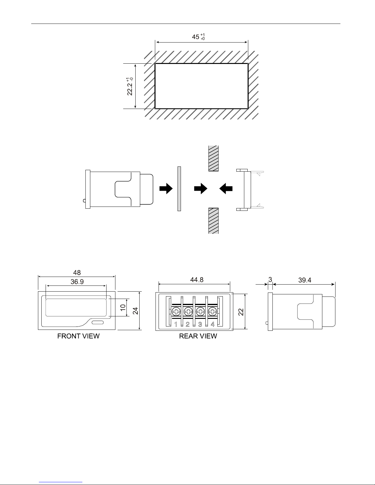
In order to assembly the unit, a 45 x 22,2 mm mounting hole (Figure 4.1) must be
prepared. Then follow the instructions mentioned below (Figure 4.2):
1. Insert gasket into the unit.
2. Insert the unit into the panel. Use the correct panel cut-out size.
3. Insert the mounting clip to the back of the unit.
4. Push the mounting clip until it locks the unit tightly against the panel.
5
Page 6
User manual for electronic counters SLE-42 and STH-42
Figure 4.1. Panel cut-out dimensions
Figure 4.2. Installing of clip and gasket
Figure 4.3. Dimensions of the case
6
Mounting Clip
Panel
Gasket
Page 7
User manual for electronic counters SLE-42 and STH-42
4.3. WIRING AND REAR TERMINALS
Attention
- Installation should be conducted by qualified personnel. During installation all
available safety requirements should be considered. The fitter is responsible for
executing the installation according to this manual, local safety and EMC
regulations.
- The power supply network cable diameter must be selected in such a way that in
the case of a short circuit of the cable from the side of the unit the cable shall be
protected against destruction with an electrical installation fuse.
- Wiring must meet appropriate standards and local regulations and laws.
- In order to secure against accidental short circuit the connection cables must be
terminated with appropriate insulated cable tips.
- Tighten the clamping screws. The recommended tightening torque is 0.5 Nm.
Loose screws can cause fire or defective operation. Over tightening can lead to
damaging the connections inside the units and breaking the thread.
- After the installation is completed do not touch the unit’s connections when it is
switched on, because it carries the risk of electrical shock.
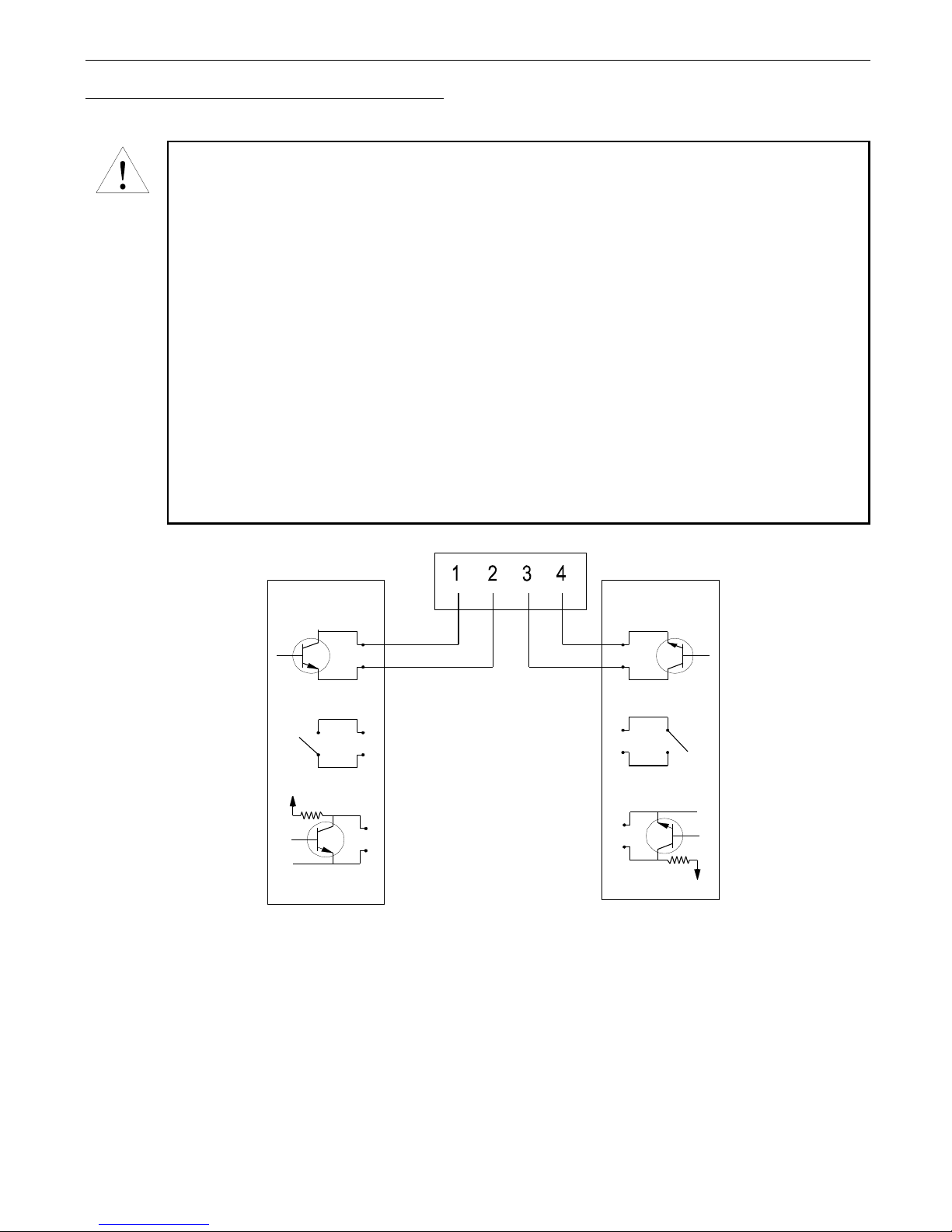
a)
7
RESET
GND
INPUT
GND
GND
2 to 30V
GND
2 to 30V
Page 8
User manual for electronic counters SLE-42 and STH-42
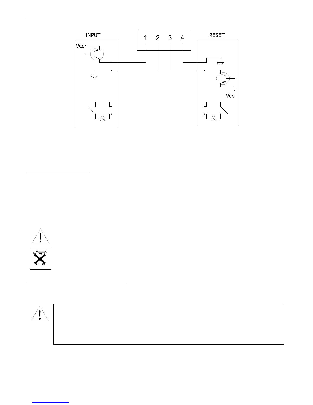
b)
Figure
4.4.
Rear terminals description:
a) version with dry contact/OC/NPN input
b) version with wide-range voltage input
4.4. MAINTENANCE
The unit (except battery) does not have any internal replaceable or adjustable
components available to the user. Pay attention to the ambient temperature in the room where
the unit is operating. Excessively high temperatures cause faster ageing of the internal
components and shorten the fault-free time of unit operation.
In cases where the unit gets dirty do not clean with solvents. For cleaning use warm water with
small amount of detergent or in the case of more significant contamination ethyl or isopropyl
alcohol.
Using any other agents can cause permanent damage to the housing.
Product marked with this symbol should not be placed in municipal waste.
Please check local regulations for disposal and electronic products.
4.5. BATTERY REPLACEMENT
Precautions when replacing the battery:
- Disconnect the wiring before changing the battery. Do not touch areas subject to
high voltages as this could result to an electric shock.
- Make sure that your body is free from static electricity before changing the battery.
- Use only 3.6V 1/2AA Lithium Battery for this unit.
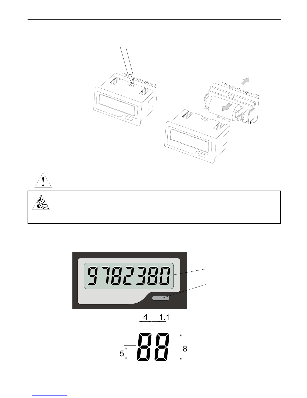
1) Use a flat screwdriver or any appropriate tool to lift the groove in order to unfasten rear case
from front case.
2) Pull out the rear case from the main body.
8
Page 9
User manual for electronic counters SLE-42 and STH-42
3) Replace with a new battery. Make sure that the positive and negative terminals of the
battery are positioned correctly.
4) Replace the rear case to the main body.
Warning!
This unit uses Lithium battery. Properly dispose the battery after use.
Do not short the positive and negative terminals, recharge, disassemble, deform,
or dispose the battery to fire as this may seriously damage it or may cause
explosion.
5. FRONT PANEL DESCRIPTION
Figure
5.1.
Size of figure
9
Count display
Reset key
(only in SLE-42)
EXPLOSIVE!
Make sure that the case hooks
click properly in place.
Page 10
User manual for electronic counters SLE-42 and STH-42
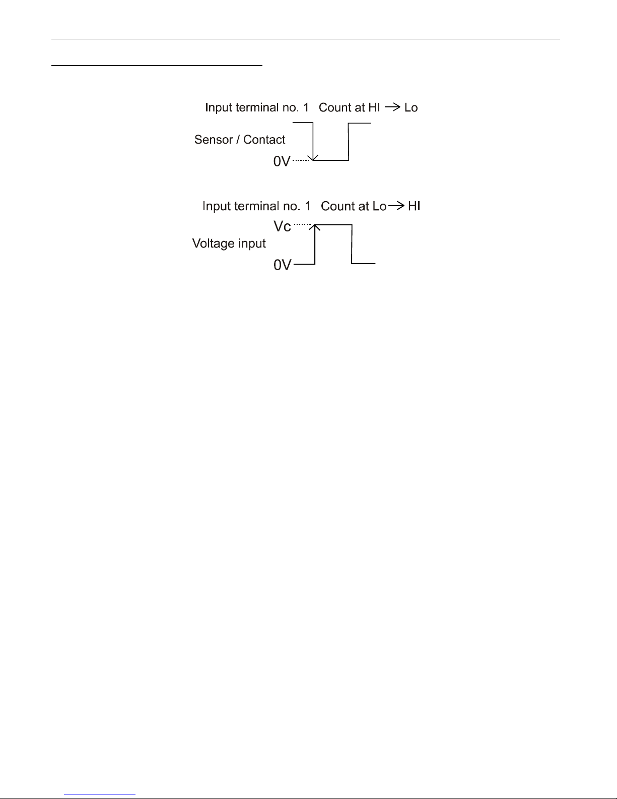
6. PRINCIPLE OF OPERATION
a)
b)
Figure 6.1. The counting principle of the
SLE-42
counters:
a) dry contact/OC/NPN input, b) wide-range voltage input
10
Page 11

User manual for electronic counters SLE-42 and STH-42
11
Page 12

SIMEX Sp. z o.o.
ul. Wielopole 7
80-556 Gdańsk
Poland
tel.: (+48 58) 762-07-77
fax: (+48 58) 762-07-70
http://www.simex.pl
e-mail: [email protected]
 Loading...