

Page 1
Assisting the automation
industry since 1986
User manual
MODULE
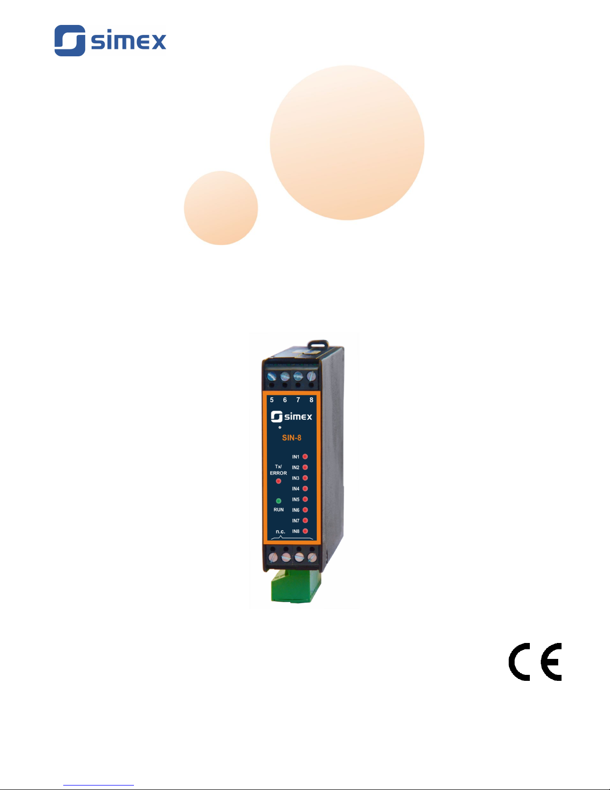
SIN-8
•
Firmware: v.2.0 or higher
•
Input type: voltage
•
Dedicated for DAQ systems
Read the user's manual carefully before starting to use the unit or software.
Producer reserves the right to implement changes without prior notice.
2013.02.08 SIN-8_INSSXEN_v.1.08.000
Page 2

User manual - MODULE SIN-8
CONTENTS
1. BASIC REQUIREMENTS AND USER SAFETY........................................................................................2
2. GENERAL CHARACTERISTICS................................................................................................................3
3. TECHNICAL DATA......................................................................................................................................3
4. DEVICE INSTALLATION............................................................................................................................4
4.1. UNPACKING.......................................................................................................................................4
4.2. CONNECTION METHOD...................................................................................................................4
4.3. MAINTENANCE..................................................................................................................................6
5. PRINCIPLE OF OPERATION.....................................................................................................................7
6. THE MODBUS PROTOCOL HANDLING...................................................................................................8
6.1. LIST OF REGISTERS........................................................................................................................9
6.2. TRANSMISSION ERRORS DESCRIPTION......................................................................................9
6.3. EXAMPLES OF QUERY/ANSWER FRAMES...................................................................................9
Explanation of symbols used in the manual:
- This symbol denotes especially important guidelines concerning the installation and
operation of the device. Not complying with the guidelines denoted by this symbol
may cause an accident, damage or equipment destruction.
IF THE DEVICE IS NOT USED ACCORDING TO THE MANUAL THE USER IS
RESPONSIBLE FOR POSSIBLE DAMAGES.
- This symbol denotes especially important characteristics of the unit.
Read any information regarding this symbol carefully
1. BASIC REQUIREMENTS AND USER SAFETY
-
The manufacturer is not responsible for any damages caused by
inappropriate installation, not maintaining the proper environmental
conditions and using the unit contrary to its assignment.
- Installation should be conducted by qualified personnel . During installation all
available safety requirements should be considered. The fitter is responsible for
executing the installation according to this manual, local safety and EMC
regulations.
- The unit must be properly set-up, according to the application. Incorrect
configuration can cause defective operation, which can lead to unit damage or
an accident.
-
If in the case of a defect of a unit malfunction there is a risk of a serious
threat to the safety of people or property additional, independent systems
and solutions to prevent such a threat must be used.
- Neighbouring and connected equipment must meet the appropriate standards
and regulations concerning safety and be equipped with adequate overvoltage
and interference filters.
2
i
!
!
Page 3

User manual - MODULE SIN-8
-
Do not attempt to disassemble, repair or modify the unit yourself. The unit
has no user serviceable parts. Defective units must be disconnected and
submitted for repairs at an authorized service centre.
The unit is designed for operation in an industrial environment and must
not be used in a household environment or similar.
2. GENERAL CHARACTERISTICS
Module type
SIN-8
allows monitoring of 8 binary inputs. Standard transmission functions
of Modbus protocol make the device registers (address, state of inputs, device ID) accessible
via RS-485 interface.
3. TECHNICAL DATA
Power supply voltage
16...24...30V DC (separated)
External fuse (required) T - type, max. 1 A
Current consumption 20mA typically
Number of independent inputs 8
Input levels - low state:
high state:
0V
24V
Galvanic isolation All inputs are galvanically isolated from module supply
and RS-485 interface
Communication interface RS 485, 8N1 / Modbus RTU
Baud rate 1200 ÷ 115200 bit/s
Number of modules in 1 network maximum 128
Data memory non-volatile memory, EEPROM type
Protection level IP 20 (housing and connection clips)
Housing type
Housing dimensions (L x W x D)
DIN rail mounted (35 mm rail)
101 x 22.5 x 80 mm
Operating temperature
(depending on version)
0°C to +50°C
or -20°C to +50°C
Storage temperature
(depending on version)
-10°C to +70°C
or -20°C to +70°C
Humidity
Altitude
5 to 90% no condensation
up to 2000 meters above sea level
Screws tightening max. torque 0.5 Nm
Max. connection leads diameter 2.5 mm
2
EMC according to: PN-EN 61326-1
3
!
!
Page 4
User manual - MODULE SIN-8
This is a class A unit. In housing or a similar area it can cause radio
frequency interference. In such cases the user can be requested to use
appropriate preventive measures.
4. DEVICE INSTALLATION
The unit has been designed and manufactured in a way assuring a high level of user
safety and resistance to interference occurring in a typical industrial environment. In order to
take full advantage of these characteristics installation of the unit must be conducted correctly
and according to the local regulations.
- Read the basic safety requirements on page 2 prior to starting the installation.
- Ensure that the power supply network voltage corresponds to the nominal
voltage stated on the unit’s identification label.
- The load must correspond to the requirements listed in the technical data.
- All installation works must be conducted with a disconnected power supply.
4.1. UNPACKING
After removing the unit from the protective packaging, check for transportation damage. Any
transportation damage must be immediately reported to the carrier. Also, write down the unit
serial number on the housing and report the damage to the manufacturer.
Attached with the unit please find:
- user’s manual,
- warranty,
4.2. CONNECTION METHOD
Caution
- Installation should be conducted by qualified personnel . During installation all
available safety requirements should be considered. The fitter is responsible for
executing the installation according to this manual, local safety and EMC
regulations.
- Wiring must meet appropriate standards and local regulations and laws.
- In order to secure against accidental short circuit the connection cables must be
terminated with appropriate insulated cable tips.
- Tighten the clamping screws. The recommended tightening torque is 0.5 Nm.
Loose screws can cause fire or defective operation. Over tightening can lead to
damaging the connections inside the units and breaking the thread.
4
!
!
!
Page 5
User manual - MODULE SIN-8
- In the case of the unit being fitted with separable clamps they should be inserted
into appropriate connectors in the unit, even if they are not used for any
connections.
- Unused clamps (marked as n.c.) must not be used for connecting any
connecting cables (e.g. as bridges), because this can cause damage to the
equipment or electric shock.
Due to possible significant interference in industrial installations appropriate measures
assuring correct operation of the unit must be applied. To avoid the unit of improper indications
keep recommendations listed below.
–
Avoid common (parallel) leading of signal cables and transmission cables together with
power supply cables and cables controlling induction loads (e.g. contactors). Such cables
should cross at a right angle.
–
Contactor coils and induction loads should be equipped with anti-interference protection
systems, e.g. RC-type.
–
Use of screened signal cables is recommended. Signal cable screens should be
connected to the earthing only at one of the ends of the screened cable.
–
In the case of magnetically induced interference the use of twisted couples of signal
cables (so-called “spirals”) is recommended. The spiral (best if shielded) must be used
with RS-485 serial transmission connections.
–
In the case of interference from the power supply side the use of appropriate antiinterference filters is recommended. Bear in mind that the connection between the filter
and the unit should be as short as possible and the metal housing of the filter must be
connected to the earthing with largest possible surface. The cables connected to the filter
output must not run in parallel with cables with interference (e.g. circuits controlling relays
or contactors).
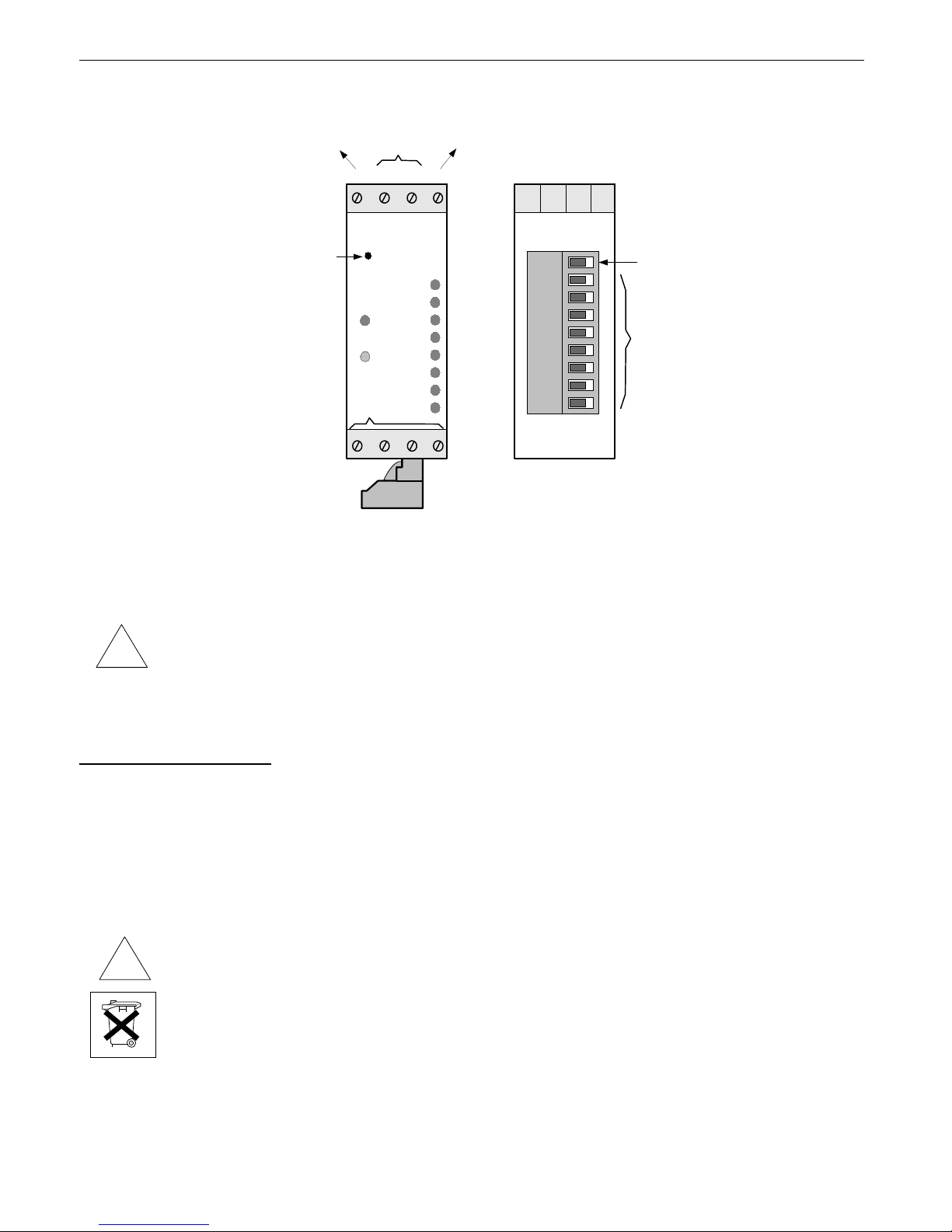
External powers supply must be connected to the module (+Uz, -Uz, typically 24V DC)
and two wires RS-485 (A+, B-) communication interface. Inputs are placed on bottom side of
the module (see: Figure 4.2).
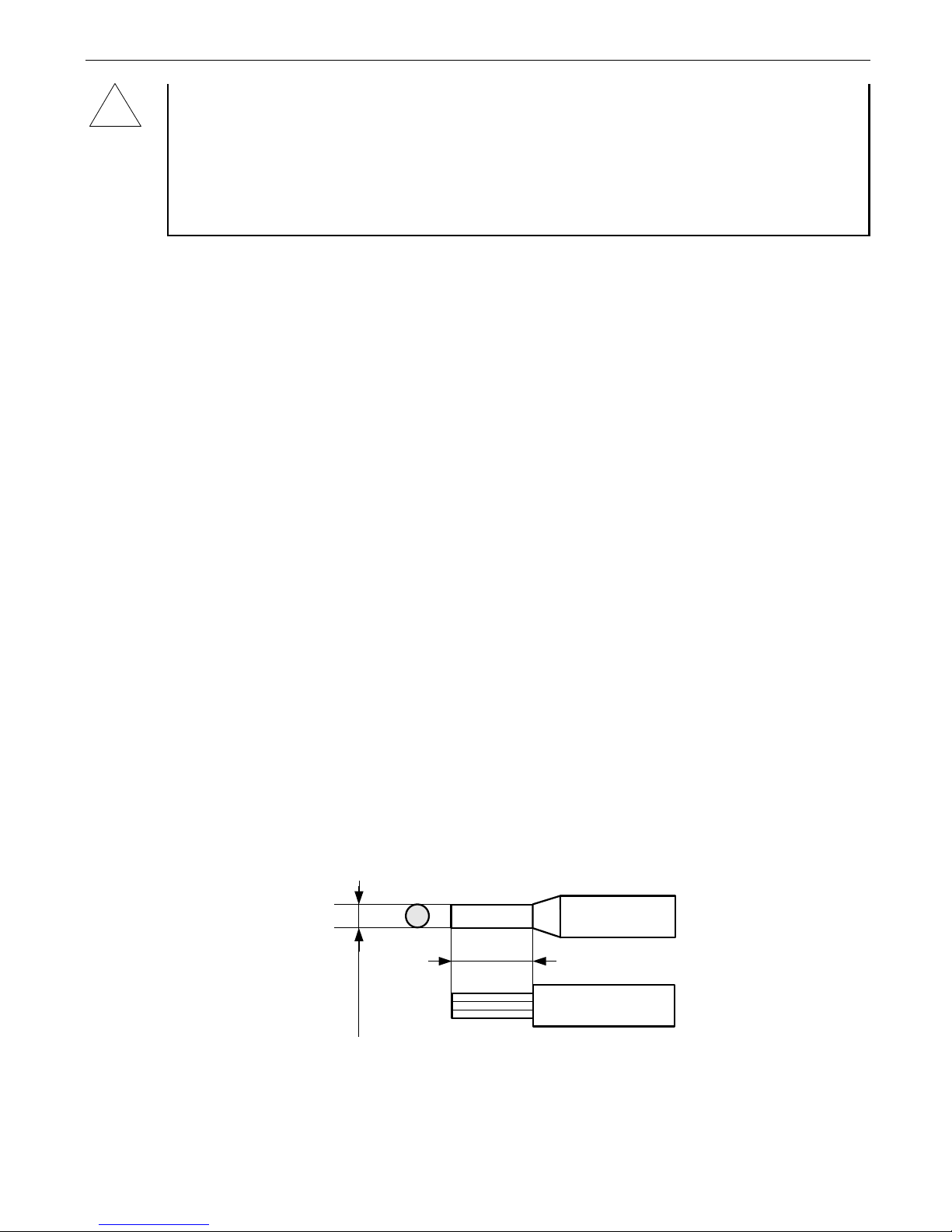
Figure 4.1. Method of cable insulation replacing and cable terminals
5
!
6-7 mm
max. 2 mm
Page 6
User manual - MODULE SIN-8
Figure 4.2. Terminals description
• When use of SMPS it is strongly recommended to connect PE wire.
• All connections must be made while power supply is disconnected !
4.3. MAINTENANCE
The unit does not have any internal replaceable or adjustable components available to
the user. Pay attention to the ambient temperature in the room where the unit is operating.
Excessively high temperatures cause faster ageing of the internal components and shorten the
fault-free time of unit operation.
In cases where the unit gets dirty do not clean with solvents. For cleaning use warm water with
small amount of detergent or in the case of more significant contamination ethyl or isopropyl
alcohol.
Using any other agents can cause permanent damage to the housing.
Product marked with this symbol should not be placed in municipal waste. Please
check local regulations for disposal and electronic products.
6
!
!
IN8
IN6
GND
IN4
IN7
IN2
IN5
IN3
IN1
voltage
inputs
(0-24V)
IN1÷IN8
inputs ground
bottom view
RS-485
SLAVE
n.c.
IN2
RUN
Tx/
ERROR
IN3
IN4
IN7
IN1
IN5
IN8
IN6
5 6 7 8
+Uz A+ B- -Uz
power supply
ground
power supply
+24V DC
front view
force address
0xFF swich
is available
through this hole
Page 7
User manual - MODULE SIN-8
5. PRINCIPLE OF OPERATION
After power on device signalizes its operation by continuous flashing of green LED
marked (RUN). Short flash of red LED (Tx/MASTER) means that some data is being
transmitted via RS-485 interface.
Green LEDs marked IN1 - IN8 signalize active state on particular binary inputs (logic HIGH
state). When particular input is in active state then corresponding register value is 01h,
otherwise its value is 00h. Register 09h contains information of all inputs compacted into
single byte, where particular bits are related to particular inputs (see
THE MODBUS
PROTOCOL HANDLING
).
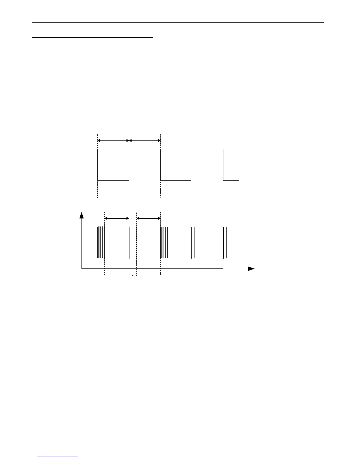
a)
b)
Figure 5.1. The traces of signals:
a) without contacts oscillations, b) with contacts oscillations
Actualisation of registers state occurs only if input signal have fulfil some time restrictions
(see Figure 5.1). These restrictions depend on settings of internal digital filter implemented in
firmware. Filter allows to eliminate signal oscillations corresponding to contacts bouncing (of
mechanical sensors). Filter is factory switched off. To ensure proper working (it means that
module do not omit any pulse) while filter is on duration of LOW (t0) and HIGH (t1) states must
be not shorter than
F×50 s
, where F means filter setting. While filter is „off” then t0 and
t
1
must be not shorter than 125 µs. See the table below (Tab. 5.1) to check proper periods for
all frequencies.
7
t0
t
1
t0
t
1
oscillations
Page 8

User manual - MODULE SIN-8
filter setting (F) t0, t
1
input signal
frequency
input type
0
125 µs
4 kHz electronic input
1
50,0 µs
10 kHz
... ... ...
electronic
255 12,75 ms 40 Hz or contact input
Tab. 5.1. Time periods t0 ,t
1
depend on filtered frequency.
Forcing of 0xFF address
New devices has set to Modbus addresses 0xFE. To enhance system installation
process special operation mode has been developed. It allows to force address 0xFF in single
module using internal momentary switch mounted on module mainboard (Figure 4.2).
To change address of the device to FFh, wait for a moment after power up until green
LED (RUN) starts flashes. Next press and hold push-button about 4 seconds until green LED
will lights permanently, then release push-button.
The device changes its MODBUS address to FFh and waits for a new address
(readdressing). Green LED (RUN) stay permanently on until readdressing via RS-485, or
power off. While module is in this state it is possible to control its inputs, and communication is
possible using temporal address FFh.
At this moment MASTER controller should find new device and readdress it (to address
other than 0xFF and 0xFE). After remote readdressing green LED indicator starts to flashes
again.
Simultaneously with change of device address, baud rate is changed to 9600 bit/s.
Required transmission speed (1200 bit/s. to 115200 bit/s.) can be set by write to register 22h.
After change of transmission speed the device sends the answer with new baud rate. While
installation of the new network it is recommended to readdress all devices using baud rate
9600 bit/s, and next change speed of all devices simultaneously, using BROADCAST query
(with address 00h).
6. THE MODBUS PROTOCOL HANDLING
Transmission parameters: 1 start bit, 8 data bits, 1 stop bit, no parity control
Baud rate: selectable from: 1200 to 115200 bits/second
Transmission protocol: MODBUS RTU compatible
The device parameters and display value are available via RS-485 interface, as HOLDINGtype registers (numeric values are given in U2 code) of Modbus RTU protocol. The registers
(or groups of the registers) can be read by 03h function, and wrote by 06h (single registers)
accordingly to Modbus RTU specification. Maximum group size for 03h function can not
exceeds 12 registers (for single frame).
The device interprets the broadcast messages, but then do not sends the answers.
8
i
Page 9
User manual - MODULE SIN-8
6.1. LIST OF REGISTERS
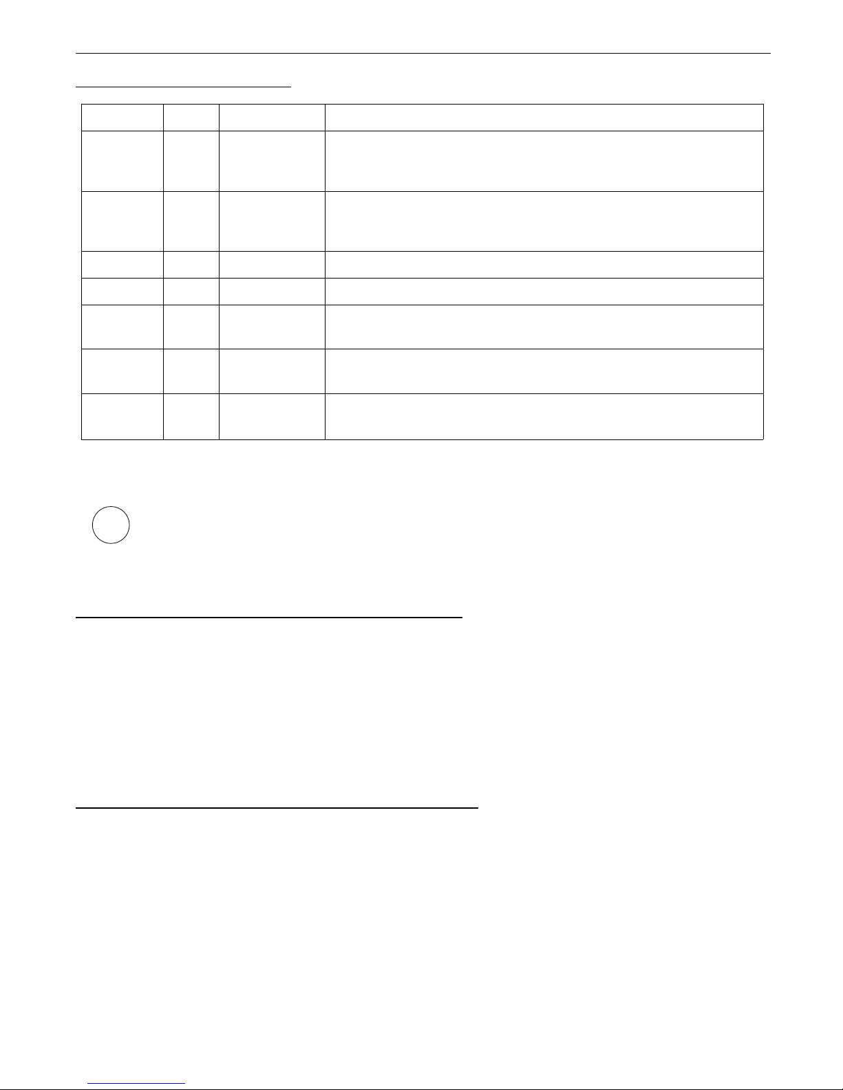
Register Write Range Register description
01h - 08h No 0 or 1
States of particular binary inputs (addresses of registers
correspond to particular inputs),
read values: 1 – HIGH state (24V) , 0 – LOW state (0V)
09h No 0 ÷ 00FFh
State of all inputs read as single register, particular bits are
related to particular inputs;
Bit 0 corresponds with input 1, bit 1 - to input 2 etc.
20h
1
Yes 1 ÷ FFh Device address. New devices has default address = FEh
21h No 008Bh Device identification code (ID)
22h
2
Yes 0 ÷ 7
Baud rate [bit/sec]: 0 - 1200; 1 - 2400; 2 - 4800; 3 - 9600;
4
- 19200; 5 - 38400; 6 - 57600; 7 - 115200
23h Yes 0 ÷ 255
Denouncing Filter state: 0 - disabled; 1 - filter setting
F
Input frequency equals: 1 / (F x 100 us)
FFF3h No 0000 ÷ FFFFh
Firmware version (hexadecimal):
e.g.: value 0123h
means version
1.23
1 - after writing to register no 20h the device responds with an “old” address in the message.
2 - after writing to register no 22h the device responds with the new baud rate.
If register 20h is being written it is possible to use BROADCAST frame (with
address 00). This operation causes changing of addresses of all modules
connected to the RS-485 network. Modules receive and interprets BROADCAST
frames, but do not transmit answers.
6.2. TRANSMISSION ERRORS DESCRIPTION
If an error occurs while write or read of single register, then the device sends an error
code according to Modbus RTU specifications.
Error codes:
01h
- illegal function (only functions 03h and 06h are available),
02h
- illegal register address
03h
- illegal data value
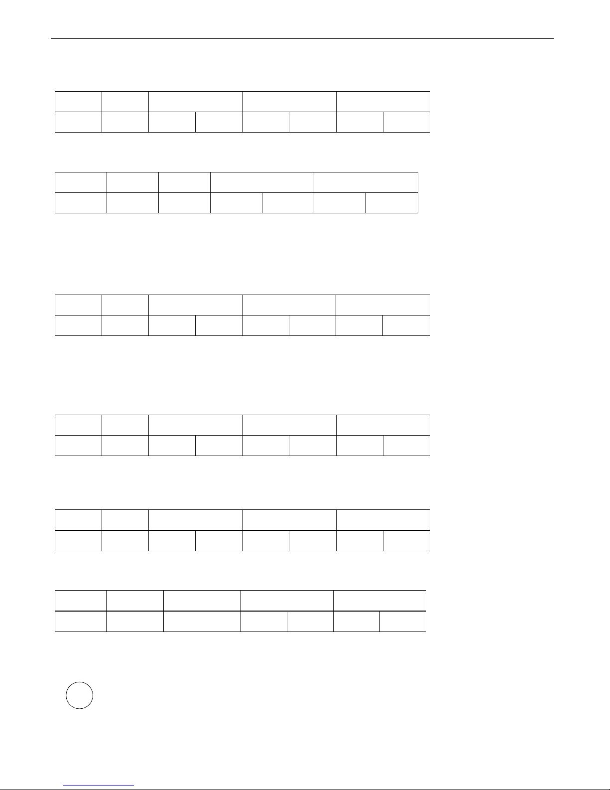
6.3. EXAMPLES OF QUERY/ANSWER FRAMES
Examples apply for device with address 1. All values are represent hexadecimal.
Field description:
ADDR
Device address on modbus network
FUNC
Function code
REG H,L
Starting address (address of first register to read/write, Hi and Lo byte)
COUNT H,L
No. of registers to read/write (Hi and Lo byte)
BYTE C
Data byte count in answer frame
DATA H,L
Data byte (Hi and Lo byte)
CRC L,H
CRC error check (Hi and Lo byte)
9
i
Page 10
User manual - MODULE SIN-8
1. Read of device ID code
ADDR FUNC REG H,L COUNT H,L CRC L,H
01 03 00 21 00 01 D4 00
The answer:
ADDR FUNC BYTE C DATA H,L CRC L,H
01 03 02 00 8B F8 23
DATA - identification code (008Bh)
2. Change of the device address from 1 to 2 (write to reg. 20h)
ADDR FUNC REG H,L DATA H,L CRC L,H
01 06 00 20 00 02 09 C1
DATA H - 0
DATA L - new device address (2)
The answer (the same as the message):
ADDR FUNC REG H,L DATA H,L CRC L,H
01 06 00 20 00 02 09 C1
3. Reading of input 5 current state.
ADDR FUNC REG H,L COUNT H,L CRC L,H
01 03 00 05 00 01 94 0B
Answer:
ADDR FUNC BYTE C DATA H,L CRC L,H
01 03 02 00 01 79 84
DATA H, L - input state (1 – it means that high state is delivered to input 5)
There is no full implementation of the Modbus Protocol in the device. The functions
presented above are available only.
10
i
Page 11

User manual - MODULE SIN-8
11
Page 12

SIMEX Sp. z o.o.
ul. Wielopole 7
80-556 Gdańsk
Poland
tel.: (+48 58) 762-07-77
fax: (+48 58) 762-07-70
http://www.simex.pl
e-mail: [email protected]
 Loading...