

Simeon 966
Dual-channel UHF soundfield FM system
User’s Manual
Système champ libre MF à deux canaux utilisant
la bande UHF
Manuel de l'utilisateur


Your new Simeon 966 soundfield FM system is easy to set up and use in any classroom. The sys-
tem can be used with a variety of microphone and speaker options and can be easily interfaced
with other audio and FM equipment. The system includes the following components:
* FM Transmitter 8LT with high capacity NiMH batteries
* Directional boom microphone 617 (or optional alternate microphone model)
* FM Transmitter/microphone 801TS with high capacity NiMH batteries
* Stretchable transmitter hip pack
* Soundfield FM receiver 966R with built-in amplifier
* Transmitter charging stand HDC-202 with dual charging pockets
Simeon 966 speaker options:
Single Omnipanel DML flat panel speaker with Speakon cable OR Four SP-966 mini wall-mount
speakers with regular speaker wire.
INSTALLATION WITH OMNIPANEL SPEAKER
Carefully unpack the soundfield system. The Omnipanel can be wall mounted with the included
hardware or may be or tripod mounted using an optional lightweight aluminum floor stand. For
wall mounting, choose a suitable location to mount the Omnipanel speaker on the classroom wall
and check that it is sufficiently close to an AC power outlet. Choose a location to mount the
Omnipanel above head level if possible. The front, back or side walls of the classroom are all suit-
able locations.
There are two methods of wall mounting the Omnipanel speaker. It can be mounted flush with the
wall 'picture style' using just two mounting screws, or it can be mounted on a special adjustable
swivel bracket. To flush mount, fasten the Omnipanel to the wall using the two screws and wall
anchors supplied. The screws must be positioned exactly 43cm apart to ensure an accurate fit.
The Omnipanel has two keyhole-shaped openings on the rear panel to accommodate these
screws. Adjust the tightness of the screws to ensure the Omnipanel frame is held firmly when
mounted on the wall (a loosely mounted Omnipanel frame may vibrate against the wall and make
audible noise). The advantage of mounting the Omnipanel flush with the wall is that it will be less
conspicuous, but it must be attached to the wall securely to avoid vibration, and is best suited to
speaker placements away from the corners of the classroom
The preferred method of mounting the Omnipanel speaker is with the special wall-mount bracket
(see below). This allows more flexibility to orient the speaker and allows it to be removed very
easily for use in another location. It also allows the Omnipanel to be mounted anywhere in the
room, even in a corner, to the fullest acoustic advantage. The bracket should be attached secure-
ly to a solid wall surface using the included hardware.
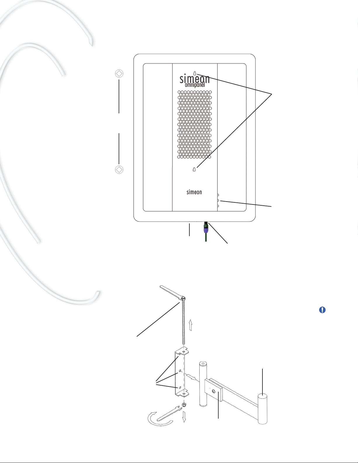
Flush mounting the Omnipanel speaker
Using the special wall bracket for mounting the Omnipanel
hang points
output for extra speaker
Speaker cable input
from receiver
Unscrew 13mm nut and
remove threaded pin to
access mounting holes
Screw base of bracket
securely against wall
using wall anchors
Bracket post fits into
socket in base of the
Omnipanel
The wall bracket offers
more flexibility and is
ideal for mounting the
Omnipanel close to the
room corners.
Be sure that the
bracket base is
attached securely
with wall anchors
into a solid wall
surface.
Bracket tilt
adjustment
Socket for tripod stand
or wall-mount bracket
To mount the Omnipanel flush with
the wall, position the wall-mounting
screws exactly 43cm apart
INSTALLATION WITH FOUR SP-966 MINI SPEAKERS
Select suitable locations for the four SP-966 mini speakers around the classroom walls. Choose
locations above head level and evenly spaced across the room to ensure the most even distribu-
tion of the soundfield. Avoid placing the speakers in the room corners and directly facing and
opposing each other as this will cause phase cancellations and result in an uneven soundfield.
For best results all four speaker should be oriented in the same general direction.
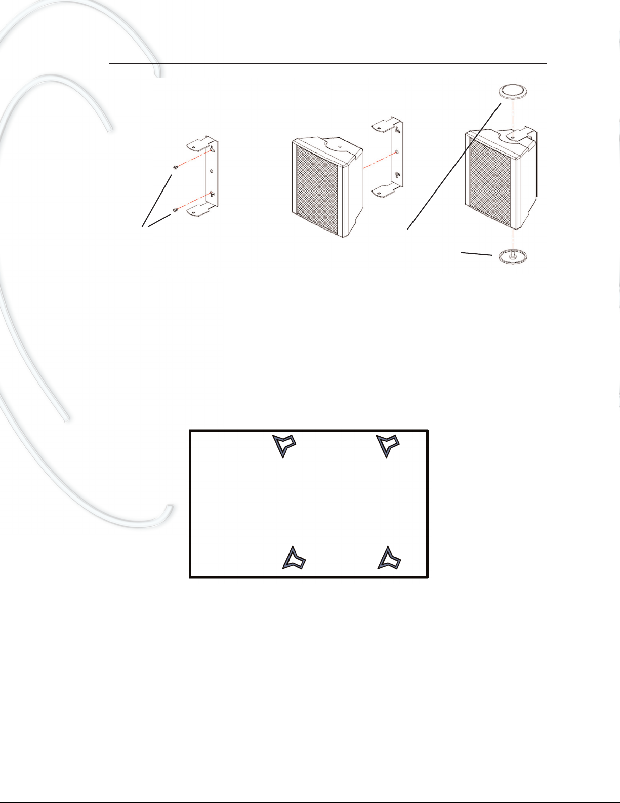
Suggested classroom configuration for four SP-966 mini-speakers
To mount the mini speakers, remove the caps from the U-bracket and secure the U-bracket to the
wall using the hardware supplied. Attach speaker wire to each speaker, taking care to observe the
correct polarity (+ve and -ve connectors), and run all four speaker wires to a central location for
the 966R receiver and close to a power outlet.
SP-966 mini-speaker trim controls
A special feature of the Simeon 966 enables individual gain adjustment of each of the four SP-
966 mini-speakers. This allows for more focal or differential amplification in different areas of the
Position the SP-966 mini
speakers so that they are
all pointing in the same
general direction.
This will ensure that they
are reinforcing and not
opposing each other.
This configuration will
result in the most uniform
soundfield distribution.
Mount U-bracket securely
to wall with wall anchors
Remove screw-fitted caps
to access U-bracket
classroom. Note that individual mini-speaker gain adjustments are made using special trimmers
located on the underside of the 966R receiver unit. Differential speaker gain adjustments should
be made in consultation with your audiologist or sound professional.
SETTING UP THE 966R RECEIVER UNIT
The 966R receiver unit has two FM receiver modules, an integrated amplifier, and multiple inputs
and outputs to connect to other audio and FM devices. It is the base station of the entire sound-
field system.
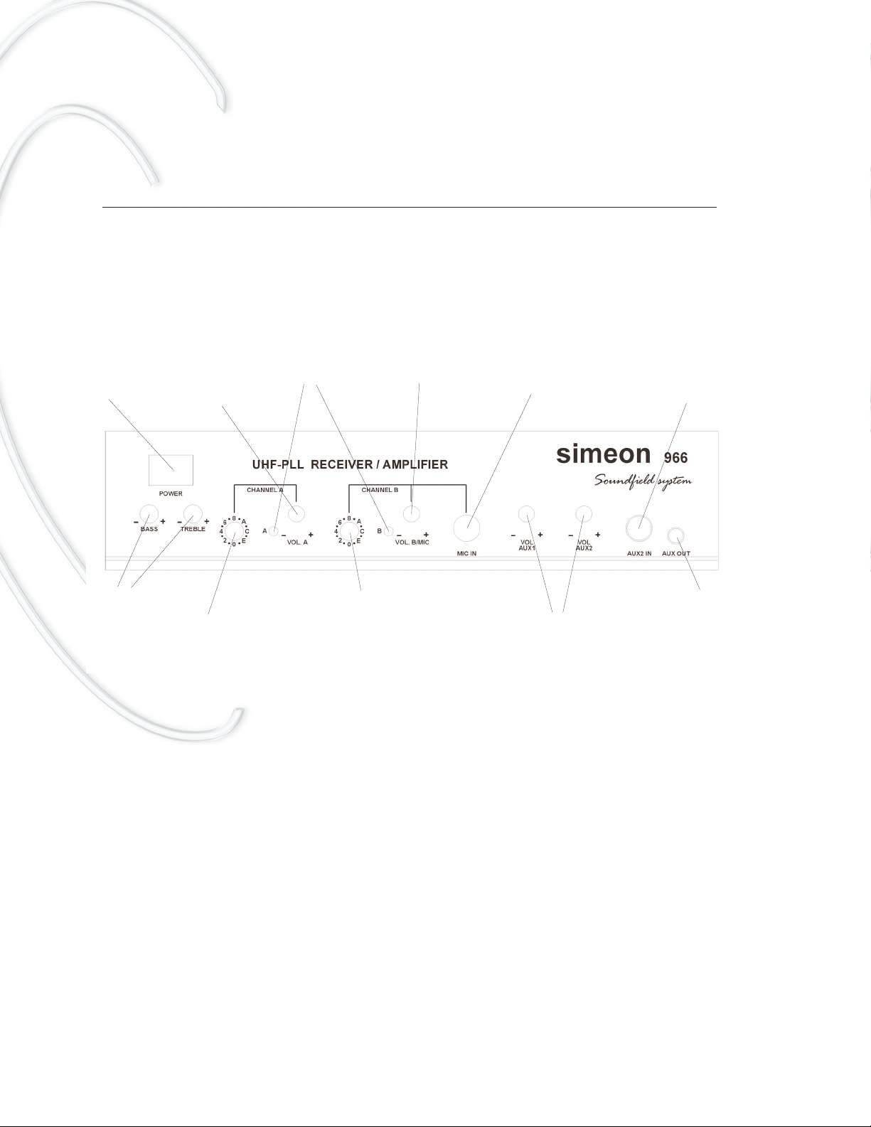
Receiver 966R - Front panel
The receiver unit itself requires no special installation, but should be placed in a suitable safe
location, such as shelving, well within reach of the speaker cables and sufficiently close to a
classroom power outlet. There are just a few short steps required to ready the 966R receiver for
use.
First, make the speaker connection. The Omnipanel speaker is connected with a single conven-
ient Speakon connector cable, which is inserted into the rear panel. Twist the Speakon plug to
lock; to release again, pull the release button on the plug. If using the SP-966 mini speakers,
these must be connected via regular speaker wire to the screw-terminals on the rear panel of the
receiver. Up to four mini-speakers can be connected to the 966R receiver. Be sure to observe the
correct polarity (+ve and -ve connectors) when connecting the mini speakers.
Next, connect the two antennae to the connectors on the rear panel. Adjust each antenna to the
vertical position for best reception. Connect the power adapter to the DC IN connector on the rear
panel of the 966R receiver. Be sure to use only the recommended and approved power adapter
Power Switch
Volume Control
(primary channel)
Channel Selector
(primary channel)
Volume Control
(secondary channel)
Channel Selector
(secondary channel)
Volume Control for
Secondary Inputs
Auxilary Output to
connect to personal
FM Transmitter
FM Signal
Indicators
Input for
Cabled Mic
Auxiliary input
(from CD, etc.)
Tone Controls
(12 - 16v DC; 1.6 amps). Note that the transmitter charging cradle model HDC-202 is also sup-
plied with its own power adapter, but the charging cradle can also be powered directly from the
DC OUT socket of the receiver model 966R using the short (15cm) DC cable supplied. This is a
convenience in classrooms with few available power outlets.
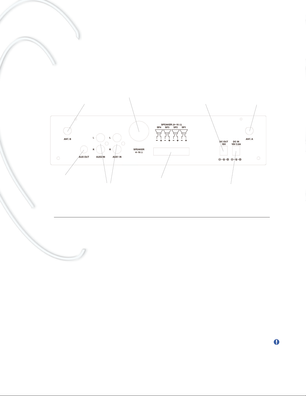
Receiver 966R - Rear panel
PREPARING THE SYSTEM FOR USE
Check that the transmitters and receiver are set to matching channels, and that the selected
channel frequencies do not conflict with other FM equipment at your school. It is important that a
separate channel is selected for each transmitter. Two transmitters cannot share the same chan-
nel without interference. Note that the Simeon 966 system is available in at least two UHF fre-
quency bands (744 - 752 MHz and 794 - 806 MHz), each with 16 FM channels. If using six or
more systems in one location, consider use the second frequency band as there are performance
considerations when multiple channels are used in very close proximity. Contact your represen-
tative if you have any difficult selecting an FM channel for your system.
FM Transmitter 8LT
Open the transmitter battery compartments as shown and insert the NiMH rechargeable batteries
supplied, taking care to observe correct battery polarity. For best performance, use only the rec-
ommended NiMH (nickel metal-hydride) rechargeable size AA transmitter batteries.
Never use disposable (alkaline) batteries in combination with the charging system.
Place the transmitters into the two charging pockets of the HDC-202 charging cradle and charge
fully before using (see Battery Care and Charging section below). When transmitter charging is
Antenna connector
Antenna connector
Speaker Connector for
OmniPanel Speaker
Low Voltage Output to
connect to Transmitter
Charging Stand model
Simeon HDC-202
Auxilary Output to
connect to personal
FM Transmitter
Auxiliary input
(from CD, etc.)
Connectors for wall-mount
SP966 Mini Speakers
Low Voltage Input from
Power Adapter
complete (3 - 6 hours charge time) the charging cradle will show a green light (Ready) below each
charging pocket.
Place the fully charged transmitter model 8LT into the hippack and adjust for comfort. Plug the
microphone into the transmitter mic jack. If using the standard Simeon 617 boom (headset) micro-
phone, place the frame over the ears and adjust the boom arm to position the mic capsule to point
to the corner of your mouth. It is not necessary to place the microphone in front of your lips and
doing so may diminish the sound quality. It is usually necessary to adjust the microphone frame
by bending so that it rests lightly over the ears, avoiding any other contact or pressure points
against the head. It is important to adjust the microphone frame in this way to ensure a comfort-
able fit. The Simeon 617 boom mic is supplied with a Velcro headband to keep the microphone
secure during vigorous activities (e.g. Phys Ed.). This band may be removed for regular class-
room use.
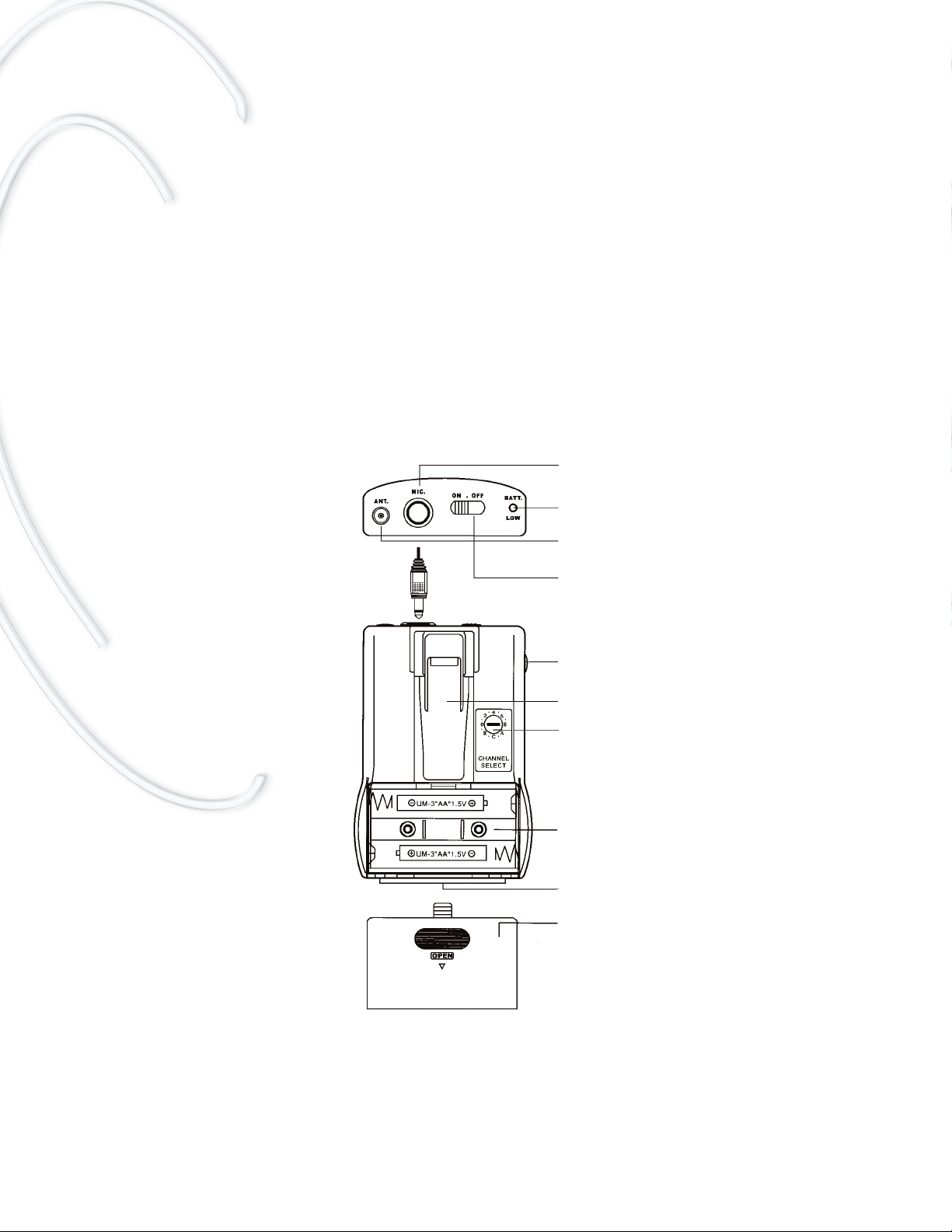
FM Transmitter 8LT
Microphone jack
Power / low battery indicator
Built-in antenna
ON / STANDBY /OFF switch
Transmitter gain (volume control)
Belt clip
Channel selector
Battery compartment
Charging contacts
Battery door
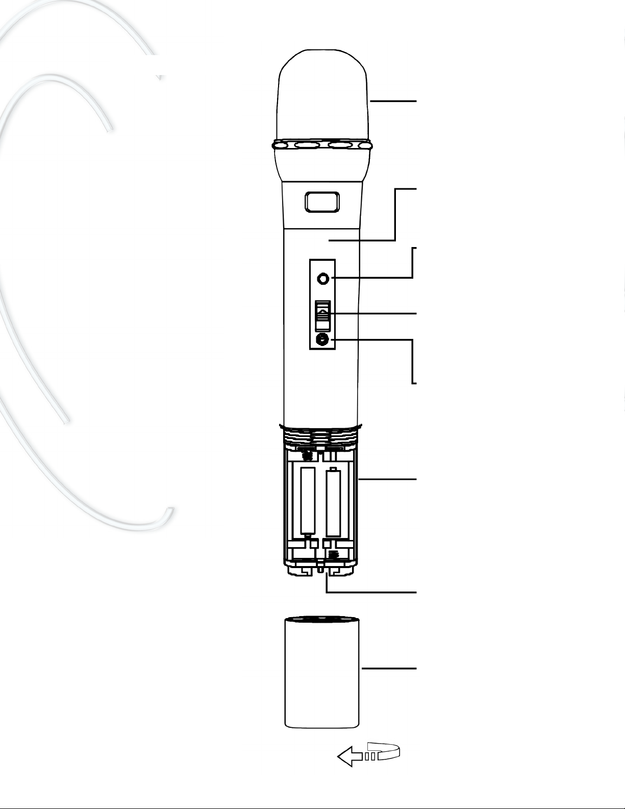
Directional capsule
Internal antenna
Power / low battery indicator
ON / STANDBY /OFF switch
Channel selector
Battery compartment
Charging contacts
Battery cover
FM Transmitter/microphone 801TS

FM Transmitter/microphone 801TS
After charging the transmitter/microphone model 801TS, remove from the charging cradle and
turn ON to use. The capsule of the 801TS transmitter/microphone is highly directional - point the
microphone directly towards the mouth to ensure the best performance. If you need to change the
channel of transmitter/microphone 801TS, there is a small key located inside the battery housing
that will fit the channel selector (please see image on next page).
Setting gain level
Check the volume positions before turning your soundfield system on! The Simeon 966R receiv-
er is equipped with two independent volume controls - one for each FM channel. In addition,
transmitter 8LT is equipped with a volume control, which is best set above ½ full-on to allow for
fine gain adjustment. Note that the transmitter/microphone 801TS has no volume control, so the
gain for this channel must be set using the 966R receiver volume controls.
To set the volume (gain) level, position the microphone correctly, turn on, and gradually increase
the volume until your amplified voice is clearly audible but not loud. Avoid excessive amplification
- soundfield FM will make speech clearly audible throughout your classroom at a comfortable lis-
tening level.
Special feature (for SP-966 mini-speakers only)
Differential gain adjustments to each of the four SP-966 mini-speaker gain adjustments may be
made using special trimmers located on the underside of the 966R receiver unit. Differential
speaker gain adjustments should be made in consultation with your audiologist or sound profes-
sional.
BATTERY CARE AND CHARGING
For best performance, use only the recommended NiMH (nickel metal-hydride) rechargeable size
AA transmitter batteries. These batteries are not susceptible to memory and can be recharged
after only partial use.
Never use disposable (alkaline) batteries in combination with the charging system.
Disposable batteries are not suitable for recharging and attempting to recharge them may result
in damage to your equipment.
Charging cradle HDC-202
The charging cradle model HDC-202 has two charging pockets, either of which will charge trans-
mitter model 8LT or transmitter/microphone model 801TS. It is good practice to charge the trans-
mitters at the end of each day. Remember to turn both transmitters OFF before placing them into
the charging pockets. The charger indicator lights show charging progress: charging (amber

LED); ready (green LED). Charge time is typically between 3 and 6 hours, depending on battery
condition. Prolonged transmitter charging is not a problem - the charging cradle will automatical-
ly prevent overcharging of the transmitter batteries (intelligent charging).
The HDC-202 charging cradle is supplied with its own AC/DC power adapter. For convenience,
the charging cradle may also be connected directly to the DC OUT socket of the 966R receiver,
thus allowing operation of both devices from a single power source. A short (15cm) DC connec-
tor cord is supplied with receiver 966R for this purpose. Note that the HDC-202 charging cradle
will always operate normally whether the 966R receiver power is turned ON or OFF.
If a transmitter has been left turned ON until the batteries are completely discharged, the charg-
er sensor may indicate 'Ready' after only a few minutes of charging time. If this happens it may
be necessary to give two or more 'priming' charges (at least 30 minutes charge time), followed by
a full 6 hour charge cycle to restore a full battery charge.
Never use disposable (alkaline) batteries in combination with the charging system.
PERSONAL FM SYSTEMS
The Simeon 966R receiver is equipped with two separate auxilliary outputs that may be connect-
ed to personal FM transmitters to accommodate students with various types of personal FM sys-
tems. These outputs are located on the front and rear panels and are labeled AUX OUT. Check
that you have the correct connection cable and have the interface checked by an audiologist to
verify the signal quality. Note that the AUX OUT gain level is controlled via the two 966R receiv-
er volume controls.
Other external connections
In addition to making connection to personal FM systems, the Simeon 966 can be interfaced with
most other audio devices, including classroom computers. There are two sets of RCA stereo input
connectors on the rear panel, and volume can be adjusted for these inputs independently of the
FM gain. It is also possible to connect a cabled pass-around microphone directly to the 966R
receiver via the MIC IN jack on the front panel.
Charging cradle HDC-202
(1) Power indicator
(2) Charging indicator (left pocket)
(3) Ready indicator (left pocket)
(4) Charging indicator (right pocket)
(5) Ready indicator (right pocket
(6) Power switch
(7) DC Power connector (use AC/DC
power adapter or plug directly into DC
OUT on 966R receiver)

USEFUL TIPS
Be sure that the two transmitters are set to separate channels and that matching channels are
selected on the Simeon 966R receiver
Adjust the Simeon 617 boom (headset) microphone for comfort. Bend the frame so that the micro-
phone is supported lightly by both ears with no pressure or contact points. Position the mic cap-
sule so that it points toward the corner or the mouth.
Wear the 8LT transmitter in the stretchable hippack. The hippack is more secure than the belt clip
and will protect the transmitter and delicate microphone from drop damage.
Keep the volume of the 8LT transmitter higher than the receiver volume setting. This allows fine
volume adjustment and helps avoid acoustic feedback.
Avoid excessive amplification - soundfield FM will make speech clearly audible throughout your
classroom at a comfortable listening level.
Avoid approaching very close to the Omnipanel or mini-speakers with the microphone turned on
- this may cause a loud squeal (acoustic feedback).
Do not adjust the tone control settings unless this has been recommended by an audiologist.
Excessive bass adjustment may degrade speech intelligibility.
For convenience, keep the HDC-202 charging stand plugged into DC OUT on the rear panel of
the 966R receiver. This allows operation from a single power source.
Use only the recommended batteries and power adapters.
Never use disposable (alkaline) batteries in combination with the charging system.
MICROPHONE CARE
The microphone is the most delicate component of your soundfield system. Protect the micro-
phone cord and plug from strain and excessive flexing. Clean the pin of the microphone plug peri-
odically with an approved electronics contact cleaner to maintain noise-free performance.
Replace damaged or missing foam windscreens and protect the microphone capsule from mois-
ture.
Simeon 617 boom (headset) microphone: this model has a unidirectional pick-up pattern. The tip
of the mic capsule must be pointed towards the corner of the mouth for proper performance.

ONE YEAR LIMITED WARRANTY
Simeon 966 soundfield FM systems are covered by a ONE year parts and labour warranty, effec-
tive from the date of purchase. Coverage applies to transmitter, receiver, charging system
(excluding batteries), power adapters and speaker system. Genuine Simeon microphones bear-
ing the Simeon brand name are warranted for ONE year. Batteries are warranted for 90 days
unless stated otherwise by the manufacturer.
The manufacturer's warranty provides for repair or replacement of defective components or work-
manship. Expressly not covered are damages resulting from abuse, neglect, and unapproved
substitution of components, batteries or accessories. Extended warranty coverage may be pur-
chased under our Service Plus program.
TROUBLESHOOTING
No sound
Check volume settings (transmitter and receiver). Check that there is power to the receiver and
that it is turned ON. Ensure that the speaker cable is connected securely. Check that the trans-
mitters are set to the ON position (not STANDBY). Verify that the 966R receiver is receiving FM
signal (indicated by green LED on receiver). Check or replace transmitter microphone.
No FM signal
Check that the selected transmitter channels are matched with the receiver channels and that
they are on the same frequency band. Check or replace transmitter batteries. Check transmitter
switch is set to ON position (not STANDBY) and that there is sufficient battery power (indicated
by green LED on transmitter).
Dead batteries
First, make sure that only the recommended NiMH (nickel metal-hydride) rechargeable size AA
transmitter batteries are in use. Check that the batteries are making good contact inside the
transmitter battery housing. Make sure that the transmitters are turned OFF during charging, and
that the charging cradle is receiving power via the correct power adapter model.
If the transmitter batteries are completely drained and are failing to charge, give two or more
'priming' charges (at least 30 minutes charge time), followed by a full 6 hour charge cycle to
restore a full battery charge.
Never use disposable (alkaline) batteries in combination with the charging system.
Weak sound
Check volume settings (transmitter and receiver). Adjust microphone position. Check or replace
microphone. Check that the correct power adapter is connected to the receiver.

Noise or Distortion
Check that the two transmitters are set to different FM channels -transmitters cannot share the
same channel without interference. Check for possible sources of radio interference (e.g. wire-
less LAN, other FM systems) and select a different FM channel pair while ensuring that the trans-
mitters are kept on separate channels. Check the microphone and the integrity of microphone
cord and plug. Clean mic plug with a recommended contact cleaner.
Acoustic Feedback
Check and adjust volume settings. Ensure that the microphone is positioned correctly. Avoid
approaching very close to the Omnipanel or mini-speakers with the microphone on.
Intermittency
Check microphone, mic cable and the plug connection with the transmitter. Replace microphone
if necessary. Check that both antennae are fitted to the rear panel of the 966R receiver, and that
the 8LT transmitter antenna is secure. Make sure that all cables are fitted securely.
SPECIFICATIONS
FM frequency range UHF 744 - 752 MHz; 794 - 806 MHz (Two approved bands)
FM Channels 16 Switchable PLL synthesized UHF channels per band
Receiver sensitivity 4 µV @ 30dB SINAD
Channel rejection 50dB
Dynamic range >100dB
RF Signal / noise ratio 70dB
Amplifier continuous power RMS 10 Watts x 4 @ 8 Ohms
Receiver inputs UHF FM channels x 2; Line level x 2; Mic level x 1
Receiver outputs Speaker level x 5, Auxilliary x 2
Transmitter battery life > 20 Hours (NiMH 1.2v x 2, 2500mAh)
Transmitter charge method Drop-in intelligent dual-pocket charging cradle
Standard microphone type Directional over-the-ear boom type
Hand-held microphone type Directional (dynamic)
Omnipanel speaker type Distributed Mode flat panel, 4 actuators
8 Ohms nominal impedance; 80 Watts max)
Audio frequency range: 100 Hz - 16KHz
SP-966 Mini-speaker type Conventional 2-way, cone driver with tweeter
8 Ohms nominal impedance; 20 Watts RMS, 40 Watts max.
Audio frequency range: 200 Hz - 12KHz
Canadian approvals IC: 3918A-8LT, IC: 3918A-801TS; IC: 3918A-966R
NOTES
Operation of this device is subject to the following two conditions:
(1) This device may not cause interference, and
(2) This device must accept any interference, including interference that may cause undesired operation of the device.
Certain notifications or licensing may apply to radio frequency equipment in your jurisdiction. Contact the local radio equipment regulating authority for your area for specific requirements.

Votre nouveau système champ libre MF Simeon 966 s'installe facilement dans une salle de
classe. Ce système peut être utilisé avec un grand nombre de microphones et de haut-parleurs
et être facilement couplé à d'autre équipement audio et MF. Il comprend les composants suiv-
ants :
Émetteur MF 8LT avec piles NiMH longue durée
Microphone serre-tête directionnel 617
(autre choix de microphone disponible sur demande)
Émetteur MF/microphone 801TS avec piles NiMH longue durée
Sac pour hanches extensible
Récepteur champ libre MF 966R avec amplificateur intégré
Embase de recharge d'émetteur à deux fentes HDC-202
Options de haut-parleurs du Simeon 966:
Un seul haut-parleur DML plat Omnipanel avec câble Speakon OU quatre haut-parleurs minia-
tures muraux SP-966 avec câble de haut-parleur régulier.
INSTALLATION AVEC HAUT-PARLEUR OMNIPANEL
Déballer avec soin le système champ libre. L'Omnipanel peut être fixé au mur à l'aide du matériel
inclus ou installé sur un trépied au moyen d'un support de plancher léger en aluminium. Pour une
installation murale, choisir un emplacement approprié pour le haut-parleur Omnipanel sur le mur
de la salle de classe et s'assurer qu'il se trouve suffisamment près d'une prise de courant. Si
possible, l'Omnipanel doit être fixé au mur à un niveau plus élevé que la tête. Les murs situés à
l'avant et à l'arrière de la classe et les murs latéraux sont tous appropriés.
Deux méthodes permettent de fixer le haut-parleur Omnipanel au mur : affleurant au mur, comme
un cadre, avec deux vis de montage, ou bien à l'aide d'un support pivotant spécial réglable. Pour
un montage à affleurement, fixer l'Omnipanel au mur à l'aide des deux vis et des dispositifs d'an-
crage fournis. Les vis doivent être placées à exactement 43 cm de distance pour s'assurer d'une
fixation précise et solide. L'Omnipanel est doté de deux points de fixation à l'arrière où ces vis
doivent être logées. Ajuster le serrage des vis pour s'assurer que le cadre de l'Omnipanel soit
fixé solidement au mur (un cadre mal fixé peut vibrer contre le mur et ces vibrations peuvent être
audibles). L'avantage d'un montage mural à affleurement est que l'Omnipanel sera moins visi-
ble, mais il doit être fixé solidement au mur pour éviter les vibrations, et il est préférable de plac-
er les haut-parleurs loin des coins de la classe.
Cependant, la méthode préférable pour fixer les haut-parleurs Omnipanel est à l'aide du support
mural spécial (voir ci-après). Cette méthode offre plus de flexibilité pour l'orientation des haut-
parleurs et permet de les enlever très facilement pour les utiliser à un autre endroit. Elle permet
également de fixer l'Omnipanel n'importe où dans la pièce, même dans un coin, et offre ainsi des
avantages acoustiques complets. Le support doit être fixé solidement sur le mur à l'aide du
matériel fourni.

Montage à affleurement du haut-parleur Omnipanel
Montage à l'aide du support mural spécial
Points de fixation
Sortie pour haut-parleur
supplémentaire
Prise du câble du
récepteur
Dévisser le boulon de 13
mm et déposer la tige
filetée pour accéder aux
trous de montage
Visser solidement la
base du support au mur
au moyen des ancrages
muraux
La tige du support loge dans
l'emboîtement à la base de
l'Omnipanel
Le support mural offre
le plus de flexibilité et
est idéal pour fixer
l'Omnipanel près des
coins de la pièce.
S'assurer que la
base du support est
bien fixée dans un
mur solide au
moyen des ancrages
muraux.
Réglage de
l'inclinaison
support
Emboîtement pour le trépied
ou le support mural
Pour un montage à affleurement, les
vis doivent être placées à exactement
43 cm de distance

INSTALLATION AVEC QUATRE HAUT-PARLEURS MINIATURES SP-966
Choisir des emplacements appropriés pour les quatre haut-parleurs miniatures SP-966 sur les
murs de la classe. Opter pour des emplacements au-dessus du niveau de la tête et à distance
égale dans la pièce pour s'assurer de la distribution la plus uniforme possible du champ libre.
Éviter de placer les haut-parleurs dans les coins de la pièce et de les pointer directement l'un
vers l'autre car cela entraînera des annulations de phase et un champ libre non uniforme.
Pour de meilleurs résultats, les quatre haut-parleurs doivent être orientés dans la même direction
générale.
Suggestion de configuration avec quatre mini-haut-parleurs SP-966
Pour fixer les haut-parleurs miniatures, retirer les capuchons du support en U et le fixer solide-
ment au mur au moyen du matériel fourni. Brancher les câbles des haut-parleurs à chaque haut-
parleur en veillant à respecter la polarité (connecteurs + et -) et relier les quatre câbles de haut-
parleur à un emplacement central pour le récepteur 966R et à proximité d'une prise de courant.
Placer les haut-parleurs
miniatures SP-966 de manière
à ce qu'ils pointent tous dans
la même direction générale.
Ceci permet de s'assurer
qu'ils ne sont pas opposés
les uns aux autres.
Cette configuration procure
la distribution la plus uniforme du champ libre
Fixer le support en U solidement au
mur au moyen des ancrages muraux
Retirer les capuchons à
vis pour accéder au support en U

Commandes de réglage des haut-parleurs miniatures SP-966
Un dispositif spécial du Simeon 966 permet un réglage individuel du gain pour chacun des qua-
tre haut-parleurs miniatures SP-966 et une amplification plus focale ou différentielle à différent
endroits dans la classe. Noter que le réglage individuel du gain des haut-parleurs miniatures se
fait au moyen de dispositifs spéciaux situés sur la face inférieure du récepteur 966R. Le réglage
différentiel du gain doit être effectué en consultation avec votre audiologiste ou professionnel du
son.
PRÉPARATION DU BLOC RÉCEPTEUR 966R
Le bloc récepteur 966R comporte deux modules récepteurs MF, un amplificateur intégré, et de
multiples entrées et sorties pour un branchement à d'autres appareils audio et MF. Il agit à titre
de station de base pour tout le système champ libre.
Récepteur 966R - Panneau avant
Le récepteur n'exige aucune installation particulière mais doit être placé à un endroit sécuritaire
approprié, par exemple, une étagère, à portée des câbles de haut-parleurs et suffisamment près
d'une prise de courant. La préparation du récepteur 966R se fait en quelques étapes seulement.
D'abord, brancher le haut-parleur. Le haut-parleur Omnipanel se branche à l'aide d'un seul câble
Speakon pratique qu'on insère dans le panneau arrière. Faire pivoter le connecteur Speakon pour
le verrouiller; pour le déverrouiller, appuyer sur le bouton situé sur le connecteur. Si vous utilisez
des haut-parleurs miniatures SP-966, ceux-ci doivent être branchés aux bornes à vis situées sur
le panneau arrière du récepteur à l'aide des câbles de haut-parleurs réguliers. Jusqu'à quatre
haut-parleurs miniatures peuvent être branchés au récepteur 966R. Veiller à respecter la polarité
(connecteurs + et -) lors du branchement des haut-parleurs miniatures.
Interrupteur
d'alimentation
Commande de volume
(canal principal)
Sélecteur de canal
(canal principal)
Commande de volume
(canal secondaire)
Sélecteur de canal
(canal secondaire)
Commande de volume
pour entrées secondaires
Prise auxiliaire pour
branchement à un
émetteur MF personnel
Voyants du
signal MF
Prise pour microphone avec câble
Prise auxiliaire
(pour CD, etc.)
Commandes
de tonalité

Ensuite, brancher les deux antennes aux connecteurs du panneau arrière. Ajuster chaque
antenne en position verticale pour une meilleure réception. Brancher l'adaptateur de courant au
connecteur DC IN situé sur le panneau arrière du récepteur 966R. Veiller à utiliser un adaptateur
de courant recommandé et approuvé (12 - 16v DC; 1,6 A). Noter que l'embase avec fentes de
recharge de l'émetteur HDC-202 est également dotée de son propre adaptateur de courant, mais
qu'elle peut aussi être alimentée directement à partir de la sortie DC OUT du récepteur 966R à
l'aide du petit câble c.c. (15cm) fourni. Ceci est très pratique dans les salles de classe avec peu
de prises de courant
Récepteur 966R - Panneau arrière
PRÉPARATION DU SYSTÈME
Vérifier que les émetteurs et le récepteur sont réglés sur le même canal et que les fréquences
sélectionnées n'entrent pas en conflit avec d'autre équipement MF de votre école. Il importe de
sélectionner un canal différent pour chaque émetteur. En effet, deux émetteurs ne peuvent
partager le même canal sans créer d'interférence. Prendre note que le système Simeon 966 est
offert avec au moins deux bandes de fréquences UHF (744 à 752 MHz et 794 à 806 MHz), cha-
cune comptant 16 canaux MF. Si vous utilisez six systèmes ou plus au même endroit, il faudrait
songer à utiliser la deuxième bande de fréquence pour assurer une bonne performance. Si vous
éprouvez de la difficulté avec la sélection d'un canal MF pour votre système, contacter votre
représentant.
ÉMETTEUR MF 8LT
Ouvrir le compartiment à piles de l'émetteur tel qu'illustré et insérer les piles NiMH rechargeables
fournies en s'assurant de respecter la polarité. Pour obtenir une performance supérieure, n'u-
tiliser que les piles NiMH (hydrure métallique de nickel) rechargeables recommandées.
Connecteur d'antenne
Connecteur d'antenne
Connecteur de haut-parleur
pour haut-parleur Omnipanel
Sortie à basse tension
pour branchement au sys-
tème de recharge d'émet-
teur Simeon HDC-202
Prise auxiliaire pour
branchement à un
émetteur MF personnel
Prise auxiliaire
(pour CD, etc.)
Connecteurs pour haut-par-
leurs miniatures muraux SP966
Prise à basse tension de
l'adaptateur de courant

Ne jamais utiliser de piles jetables (alcalines) avec le système de recharge
Placer les émetteurs dans les deux fentes du système de recharge HDC-202 et recharger avant
l'utilisation (voir la section Entretien et recharge des piles ci-après). Lorsque la recharge de
l'émetteur est terminée (après 3 à 6 heures), un voyant vert (prêt) s'allume sous chaque fente de
recharge.
Placer l'émetteur 8LT entièrement rechargé dans le sac pour hanches et l'ajuster pour votre con-
fort. Brancher le microphone dans la prise microphone de l'émetteur. Si vous utilisez le micro-
phone serre-tête standard Simeon 617, placer la base du microphone au-dessus des oreilles et
ajuster le bras du microphone serre-tête de manière à ce que la capsule microphonique pointe
vers le coin de votre bouche Il n'est pas nécessaire de placer le microphone devant vos lèvres
car cela pourrait diminuer la qualité sonore. Il est habituellement nécessaire d'ajuster le cadre du
microphone en l'incurvant afin qu'il se retrouve juste au-dessus des oreilles et en évitant tout
point de contact ou de pression sur la tête. Il est important d'ajuster le cadre du microphone de
manière confortable. Le microphone Simeon 617 est doté d'un serre-tête en velcro qui garde le
microphone en place pendant les activités intenses (p.ex.éducation physique). Ce serre-tête
peut être retiré pour utilisation dans une salle de classe régulière.
Émetteur MF 8LT
Prise microphone
Voyant d'alimentation / pile faible,
Vert = OK, Rouge = PILE FAIBLE
Antenne intégrée
Interrupteur ON / STANDBY
(ATTENTE) /OFF
Commande de gain (volume)
Pince de ceinture
Sélecteur de canaux
Compartiment à piles
Éléments de contact de recharge
Ouverture du compartiment à piles

Capsule directionnelle
Antenne intégrée
Voyant de mise sous tension / pile faible
Interrupteur ON / STANDBY (ATTENTE) /OFF
Sélecteur de canaux
Compartiment à piles
Éléments de contact de recharge
Ouverture du compartiment à piles
Émetteur MF/microphone 801TS

Émetteur MF/microphone 801TS
Après avoir rechargé l'émetteur/microphone 801TS, le retirer de l'embase de recharge et l'al-
lumer. La capsule microphonique de l'émetteur/microphone 801TS est hautement directionnelle
et le microphone doit pointer vers le coin de la bouche pour assurer la meilleure performance
possible. Si vous devez changer le canal de l'émetteur/microphone 801TS, une petite clé adap-
tée au sélecteur de canaux se trouve à l'intérieur du compartiment à piles (voir l'image à la page
suivante).
Réglage de la commande de gain
Vérifier la position du volume avant d'allumer votre système champ libre! Le récepteur 966R
est muni de deux commandes de volume indépendantes - une pour chaque canal MF. L'émetteur
8LT est également pourvu d'une commande de volume, qu'il préférable de régler à un peu plus
de la moitié de sa capacité pour permettre un réglage précis du gain. Noter que l'émetteur/micro-
phone 801TS ne comporte pas de commande de volume, donc le gain pour ce canal doit être
réglé à l'aide des commandes de volume du récepteur 966R
Pour régler le volume (gain), positionner le microphone correctement, l'allumer, puis augmenter
graduellement le volume jusqu'à ce que votre voix amplifiée soit clairement audible sans être trop
forte. Éviter une amplification excessive - le système champ libre FM rend la voix clairement
audible dans toute la salle de classe à un niveau d'écoute confortable.
Dispositif spécial (pour les haut-parleurs miniatures SP-966 seulement)
Le réglage différentiel du gain de chacun des quatre haut-parleurs miniatures SP-966 peut être
effectué au moyen d'un dispositif spécial situé sur la face inférieure du récepteur 966R. Ce
réglage doit être effectué en consultation avec votre audiologiste ou professionnel du son.
ENTRETIEN ET RECHARGE DES PILES
Pour obtenir une performance supérieure, n'utiliser que les piles NiMH (hydrure métallique de
nickel) AA rechargeables recommandées pour l'émetteur. Ces piles peuvent être rechargées
sans avoir été complètement déchargées.
Ne jamais utiliser de piles jetables (alcalines) avec le système de recharge. Les piles jeta-
bles ne sont pas faites pour être rechargées et si vous tentez de les recharger, vous pour-
riez endommager votre équipement.
Embase avec fentes de recharge HDC-202
L'embase HDC-202 est munie de deux fentes de recharge, chacune permettant de recharger
l'émetteur 8LT ou l'émetteur/microphone 801TS. Il est bon de recharger les émetteurs après
chaque journée d'utilisation. Éteindre les émetteurs et les placer dans les fentes de recharge.

Le témoin de charge indique l'état de la recharge : chargement en cours (voyant rouge); prêt
(voyant vert). Le temps de recharge est environ de 3 à 6 heures selon l'état de la pile. La
recharge prolongée de l'émetteur ne constitue pas un problème - l'embase empêchera automa-
tiquement de trop recharger les piles de l'émetteur (recharge intelligente).
L'embase avec fentes de recharge HDC-202 est dotée de son propre adaptateur de courant. Aux
fins de commodité, l'embase peut également être branchée directement dans la sortie DC OUT
du récepteur 966R, ce qui permet aux deux appareils d'utiliser la même source d'alimentation.
Un petit câble c.c. (15cm) est fourni à cet effet. Ceci est très pratique dans les salles de classe
avec peu de prises de courant. Noter que l'embase HDC-202 fonctionnera normalement que le
récepteur 966R soit allumé ou éteint.
Si un émetteur a été laissé allumé et que les piles sont entièrement déchargées, le chargeur peut
indiquer " Prêt " après quelques minutes seulement de recharge. Si cela se produit, il peut être
nécessaire de procéder à au moins deux recharges " d'amorçage " (d'au moins 30 minutes cha-
cune), suivies d'un cycle de recharge complet de 6 heures afin de récupérer la charge complète
Ne jamais utiliser de piles jetables (alcalines) avec le système de recharge.
SYSTÈMES MF PERSONNELS
Le récepteur 966R est équipé de deux prises auxiliaires qui peuvent être branchées à des émet-
teurs MF personnels pour satisfaire aux besoins des étudiants ayant divers types de systèmes
MF personnels. Ces prises sont situées sur les panneaux avant et arrière et portent la mention "
AUX ". Veuillez vous assurer de disposer du bon câble de connexion et faire vérifier la qualité du
signal de l'interface par un audiologiste. Noter que le niveau de gain des prises auxiliaires est
contrôlé par les deux commandes de volume du récepteur 966R.
Autres branchements externes
En plus de se brancher à des systèmes MF personnels, le Simeon 966 peut être couplé à divers
autres dispositifs audio, par exemple, un ordinateur. Deux séries de connecteurs RCA stéréo se
Système de recharge HDC-202
(1) Voyant de mise sous tension
(2) Voyant de recharge (fente gauche)
(3) Voyant " Ready " (prêt) (fente gauche)
(4) Charging indicator (right pocket)
(5) Voyant " Ready " (prêt) (fente droite)
(6) Interrupteur d'alimentation
(7) Connecteur d'alimentation c.c. (utiliser
un adaptateur de courant c.a. /c.c. ou brancher
directement dans la sortie DCOUT du récepteur
966R)

trouvent sur le panneau arrière, et le volume de ces entrées peut être réglé indépendamment du
gain MF. Il est aussi possible de brancher un microphone à main avec fil directement dans le
récepteur 966R au moyen de la prise MIC IN située sur le panneau avant.
CONSEILS UTILES
Vérifier que les deux émetteurs sont réglés sur des canaux différents et que des canaux iden-
tiques sont sélectionnés sur le récepteur 966R
Ajuster le microphone serre-tête directionnel Simeon 617 pour votre confort. Incurver le cadre du
microphone afin qu'il soit supporté légèrement par les oreilles, sans qu'il y ait de points de con-
tact ou de pression. Placer la capsule microphonique de manière à ce qu'elle pointe vers le coin
de votre bouche.
Placer l'émetteur 8LT dans le sac pour hanches extensible. Ce sac est plus sécuritaire que la
pince de ceinture et protégera l'émetteur et le microphone délicat contre les chutes.
Garder le volume de l'émetteur 8LT plus élevé que celui du récepteur. Ceci permet un réglage du
volume précis et élimine la rétroaction (Larsen).
Éviter une amplification excessive - le système champ libre FM rend la voix clairement audible
dans toute la salle de classe à un niveau d'écoute confortable.
Éviter d'approcher très près de l'Omnipanel ou des haut-parleurs miniatures avec le microphone
allumé car cela pourrait causer un sifflement ou une rétroaction du haut-parleur (Larsen).
Ne pas ajuster les paramètres de la commande de tonalité à moins que cela n'ait été recom-
mandé par un audiologiste.
Un réglage excessif des basses peut diminuer l'intelligibilité.
Aux fins de commodités, garder le système de recharge HDC-202 branché dans la sortie DC OUT
au panneau arrière du récepteur 966R, ce qui permet de n'utiliser d'une source d'alimentation.
N'utiliser que les piles et adaptateurs de courant recommandés.
Ne jamais utiliser de piles jetables (alcalines) avec le système de recharge.

ENTRETIEN DES MICROPHONES
Le microphone est la composante la plus délicate de votre système champ libre. Protéger le cor-
don d'alimentation et la fiche contre une déformation et une flexion excessives. Nettoyer
régulièrement la fiche du microphone avec un solvant approuvé pour éviter l'accumulation de par-
asites. Remplacer les pare-vent en mousse endommagés ou manquants et protéger la capsule
microphonique contre l'humidité.
Microphone serre-tête Simeon 617 : avec ce modèle unidirectionnel, l'extrémité de la capsule
microphonique doit pointer vers le coin de la bouche pour assurer une performance adéquate.
GARANTIE LIMITÉE D'UN AN
Les systèmes champ libre MF Simeon 966 sont protégés par une garantie d'UN an sur les pièces
et la main-d'œuvre, qui entre en vigueur à compter de la date d'achat. La protection s'applique
à l'émetteur, au récepteur, au système de recharge (à l'exclusion des piles), aux adaptateurs de
courant et au système de haut-parleurs. Les microphones Simeon d'origine arborant la marque
Simeon sont garantis UN an. Les piles sont garanties 90 jours, à moins qu'il n'en soit précisé
autrement par le fabricant.
La garantie du fabricant comprend la réparation ou le remplacement des composants défectueux
ou la main-d'œuvre. Les dommages causés par un abus, par la négligence, et par une substitu-
tion non autorisée de composantes, de piles ou d'accessoires sont formellement exclus. Une
garantie prolongée peut être achetée en vertu de notre programme de contrat de service pro-
longé.
DÉPANNAGE
Aucun son
Vérifier les réglages du volume (émetteur et récepteur). S'assurer que le récepteur est alimenté
et allumé. Vérifier que le câble du haut-parleur est branché correctement. Vérifier que les émet-
teurs sont à la position ON (et non STANDBY (ATTENTE)). Vérifier que le récepteur 966R reçoit
un signal MF (indiqué par un DEL vert sur le récepteur). Vérifier ou remplacer le microphone de
l'émetteur.
Aucun signal MF
Vérifier que l'émetteur et le récepteur sont réglés sur le même canal et la même bande de
fréquence. Vérifier ou remplacer les piles de l'émetteur. Vérifier que l'interrupteur de l'émetteur
est à la position ON (et non STANDBY(ATTENTE)) et que la pile est suffisamment chargée
(voyant vert sur l'émetteur).

Piles déchargées
Vérifier d'abord que seules les piles NiMH (hydrure métallique de nickel) AA rechargeable recom-
mandées sont utilisées pour l'émetteur. S'assurer que les piles sont insérées correctement et
qu'elles sont bien en contact à l'intérieur du boîtier. S'assurer que les émetteurs sont éteints
pendant la recharge et que le système de recharge est alimenté par un adaptateur approprié. Si
l'émetteur a été laissé allumé, que les piles sont entièrement déchargées et ne se
rechargent pas, procéder à au moins deux recharges " d'amorçage " (d'au moins 30 minutes
chacune), suivies d'un cycle de recharge complet de 6 heures afin de récupérer la charge
complète.
Ne jamais utiliser de piles jetables (alcalines) avec le système de recharge.
Son faible
Vérifier le réglage du volume (émetteur et récepteur). Ajuster la position du microphone. Vérifier
ou remplacer le microphone. Vérifier que l'adaptateur de courant approprié est branché au
récepteur.
Bruit ou distorsion
Vérifier que les deux émetteurs sont réglés sur un canal différent -- deux émetteurs ne peuvent
partager le même canal sans interférence. Vérifier la possibilité de sources de brouillage
radioélectrique (p.ex., ordinateurs ou autres systèmes MF à proximité) et sélectionner une paire
de canaux MF différents tout en vous assurant que les émetteurs sont réglés sur des canaux dif-
férents. Vérifier le microphone et l'intégrité du cordon d'alimentation et de la fiche du microphone.
Nettoyer la fiche du microphone à l'aide d'un solvant recommandé.
Larsen
Vérifier le volume et le régler. Vérifier que le microphone est positionné correctement. Éviter
d'approcher très près de l'Omnipanel ou des haut-parleurs miniatures avec le microphone allumé.
Fonctionnement intermittent
Vérifier le microphone, le câble du microphone et le branchement de la fiche dans l'émetteur.
Remplacer le microphone le cas échéant. Vérifier que les deux antennes sont fixées au panneau
arrière du récepteur 966R et que l'antenne de l'émetteur 8LT est bien fixée. S'assurer que tous
les câbles sont bien branchés.

SPECIFICATIONS
Fréquences porteuses UHF, 744 à 752 MHz; 794 à 806 MHz
(deux bandes approuvées)
Canaux MF 16 canaux UHF synthétisés au PLL sélectionnables par bande
Receiver sensitivity Rapport SINAD de 4 µV à 30 dB
Rejection de canal 50dB
Plage dynamique >100dB
Rapport signal RF/bruit 70dB
Puissance continue de l'amplificateur 10 W RMS max. x 4 @ 8 ohms
Entrées du récepteur Canaux MF UHF x 2; niveau ligne x 2; niveau microphone x 1
Sorties du récepteur Niveau haut-parleur x 5, auxiliaires x 2
Autonomie de l'émetteur > 20 heures (NiMH 1,2 V x 2, 2 500 mAh)
Méthode de recharge de l'émetteur Embase avec deux fentes de recharge
Microphone standard Microphone serre-tête directionnel
Microphone émetteur à main Dynamique (directionnel)
Haut-parleur Omnipanel DMA plat, 4 transducteurs
(impédance nominale 8 ohms; 80 W max.)
Réponse en fréquence : 100 Hz - 16KHz
Haut-parleurs miniatures SP-966 Diaphragme conique bidirectionnel conventionnel avec tweeter
(impédance nominale 8 ohms; 20 W RMS, 40 W max.)
Réponse en fréquence : 200 Hz - 12KHz
Approbation canadienne IC: 3918A-8LT, IC: 3918A-801TS; IC: 3918A-966R
REMARQUES
L'utilisation de cet appareil devrait être conforme aux exigences suivantes:
(1) Cet appareil ne peut causer d'interférence,
(2) Cet appareil doit accepter toute forme d'interférence, y compris celle pouvant entraîner un fonctionnement indésirable de
l'appareil. Certaines notifications ou licences peuvent s'appliquer à l'équipement MF dans votre juridiction. Contacter les
organismes de réglementation de l'équipement de radio locaux pour connaître les exigences

SUPPORTIVE HEARING SY ST EM S
http://www.fmhearing.com
283 MacPherson Ave.,
Toronto, ON, M4V 1A4
CANADA
Phone: 1-(800) 73 2- 88 04
Fax: 1-(800) 597-3143
E-mail: customerservice@fmhearing.com
 Loading...