

Sime Open Hybrid MEM 30-009, Open Hybrid MEM 25-009, Open Hybrid MEM 35-006, Open Hybrid MEM 30-006, Open Hybrid MEM 35-009 Installation And Maintenance Manual
...
Fonderie SIME S.p.A.
6322912 - 03/2016 - R3
INSTALLATION AND MAINTENANCE MANUAL
OPEN HYBRID MEM ErP
Dear Customer,
Thank you for purchasing an
Open Hybrid MEM ErP
system, a last generation appliance, with all the technical and performance
features to satisfy your needs for heating and the supply of domestic hot water, in maximum safety and with low running costs.
We recommend that your new appliance is started up within 30 days from the date of installation by qualified technicians,
so that you can benefit from both the legal warranty and the conventional warranty provided by
Sime
which is to be found
at the end of this manual.
EN

2
RANGE
MODEL CODE
Open Hybrid MEM 25-006 8114400
Open Hybrid MEM 25-009 8114401
Open Hybrid MEM 25-012 8114402
Open Hybrid MEM 30-006 8114403
Open Hybrid MEM 30-009 8114404
Open Hybrid MEM 30-012 8114405
Open Hybrid MEM 35-006 8114406
Open Hybrid MEM 35-009 8114407
Open Hybrid MEM 35-012 8114408
Open Hybrid MEM 25-006 S 8114409
Open Hybrid MEM 25-009 S 8114410
Open Hybrid MEM 25-012 S 8114411
Open Hybrid MEM 30-006 S 8114412
Open Hybrid MEM 30-009 S 8114413
Open Hybrid MEM 30-012 S 8114414
Open Hybrid MEM 35-006 S 8114415
Open Hybrid MEM 35-009 S 8114416
Open Hybrid MEM 35-012 S 8114417
COMPLIANCE
Our company declares that
OPEN HYBRID MEM ErP
systems
comply with the following directives:
– Gas Appliances Directive 2009/142/EC
– Low Voltage Directive 2006/95/EC
– Electromagnetic Compatibility Directive 2004/108/EC
– Ecodesign Directive 2009/125/EC
– Regulation (UE) N. 811/2013 - 813/2013
SYMBOLS
a
DANGER
To indicate actions which, if not carried out correctly,
can result in injury of a general nature or may damage or cause the appliance to malfunction; these
actions therefore require particular caution and adequate preparation.
f
DANGER
To indicate actions which, if not carried out correctly, could lead to injury of an electrical nature; these
actions therefore require particular caution and adequate preparation.
d
IT IS FORBIDDEN
To indicate actions which MUST NOT BE carried out.
m
WARNING
To indicate particularly important and useful information.
TABLE OF CONTENTS
1 SYSTEM DESCRIPTION 4
1.1 Operation ......................................5
1.1.1 Domestic hot water . . . . . . . . . . . . . . . . . . . . 5
1.1.2 Heating .............................. 5
1.1.3 Cooling .............................. 6
1.1.4 Anti-freeze function .................... 6
1.1.5 Anti-blocking function .................. 6
1.1.6 Photovoltaic function ................... 6
1.1.7 Automatic filling function ............... 6
1.1.8 Automatic degassing function ........... 6
1.2 Structure ......................................7
1.3 Technical data ..................................8
1.3.1 Boiler ................................ 8
1.3.2 Heat pump............................ 9
1.4 Main water circuits .............................10
1.4.1 Open Hybrid MEM ErP base............. 10
1.4.2 Open Hybrid MEM ErP base - High
Temperature kit....................... 10
1.4.3 Open Hybrid MEM ErP base - High
Temperature Kit - Solar Kit ............. 11
1.5 Sensors.......................................12
1.6 Expansion vessels ..............................12
1.7 Circulation pump ..............................12
1.7.1 High temperature system pump ......... 12
1.7.2 Low temperature system pump.......... 12
1.7.3 Pump equipped with LED............... 12
1.8 Mem Remote Control ...........................13
1.9 Electrical panel ................................13
1.10 Wiring diagram ................................14
2 INSTALLATION 16
2.1 Receiving the product ...........................16
2.2 Dimensions ...................................16
2.3 Handling ......................................16
2.4 Installation of the Open Hybrid Mem ErP System ....16
2.4.1 Heat pump installation................. 20
2.5 Smoke outlet and combustion air inlet .............21
2.5.1 Openings in the frame to allow the passage
of the smoke outlet.................... 21
2.5.2 Separate ducts (Ø 60/100mm) ........... 22
2.5.3 Separate ducts (Ø 60mm and Ø 80mm) ... 22
2.6 Mem Remote Control Installation .................23
2.7 Solar thermal storage tank connections............23
2.8 Position of the sensors . . . . . . . . . . . . . . . . . . . . . . . . . . 24
2.9 Electrical connections...........................25
2.9.1 Connection to the mains ............... 25
2.9.2 Component connections................ 25
2.9.3 Boiler connections .................... 25
2.10 Filling operations...............................26
2.10.1 Automatic degassing function ........... 27
2.10.2 Setting boiler parameters .............. 27
2.11 Emptying operations ............................28
3 COMMISSIONING 29
3.1 Preliminary operations ..........................29
3.2 Commissioning ................................29
3.3 Parameter setting and display ....................30
3.4 Complete list of parameters......................31
3.5 Parameter functions ............................34
3.5.1 General settings ...................... 34
3.5.2 Generation System Settings............. 35
3.5.3 Input and Output Configuration .......... 37
3.5.4 Heating ............................. 38
3.5.5 Cooling.............................. 40
3.5.6 DHW................................ 41
3.5.7 Energy Settings....................... 42
3.5.8 Communication....................... 43
4 MAINTENANCE 44
4.1 Adjustments...................................44
4.2 Alarms .......................................44
4.3 Any pump faults and possible solutions ............46
4.4 Alarm log .....................................46
5 APPLICATION DIAGRAMS 47
6 PRODUCT DATA SHEET 55

3
SAFETY WARNINGS AND REGULATIONS
m
WARNINGS
– After having removed the packaging make sure
that the product supplied is integral and complete
in all its parts. If this is not the case, please contact the Dealer who sold the appliance.
– The appliance must be used as intended by
Sime
who is not responsible for any damage caused to
persons, animals or things, improper installation,
adjustment, maintenance and improper use of the
appliance.
– In the event of water leaks, disconnect the appli-
ance from the mains power supply, close the water
mains and promptly inform professionally qualified personnel.
– Periodically check that the operating pressure of
the water heating system when cold is
1,0-1,2 bar
.
If this is not the case, increase the pressure or
contact professionally qualified personnel.
– If the appliance is not used for a long period of
time,
ONLY WHEN THERE IS THE RISK OF FREEZING
,
at least one of the following operations must be
carried out:
-
set the main system switch to "OFF";
-
close the gas and water valves for the water
heating system.
– If there is the risk of freezing, leave the gas valves
open and ensure the appliance is connected to the
mains power. This way the anti-freeze function will
remain active if set appropriately.
– In order to ensure optimal appliance operations
Sime
recommends that maintenance and checks
are carried out
ONCE A YEAR.
m
WARNINGS
–
It is recommended that all operators
read this manual carefully in order to use the appliance in a safe
and rational manner.
–
This manual
is an integral part of the appliance. It
must therefore be kept for future reference and
must always accompany the appliance in the event
the appliance is transferred or sold to another
Owner or User or is installed on another system.
–
Installation and maintenance
of this appliance must
be carried out by a qualified company or by a professionally qualified technician in accordance with
the instructions contained in the manual. The
company or technician will, at the end of installation operations, issue a statement of compliance
with national and local Technical Standards and
Legislation in force
RESTRICTIONS
d
IT IS FORBIDDEN
– The appliance is not to be used by children or un-
assisted disabled persons.
– Do not use electrical devices or appliances such as
switches, electrical appliances etc if you can smell
fuel. If this should happen:
-
open the doors and windows to air the room;
-
close the gas isolation device;
-
promptly call for professional assistance.
– Do not touch the appliance with bare feet or with
any wet part of the body.
– Do not carry out any technical intervention or
cleaning operation before having disconnected
the appliance from the mains power by setting the
main switch to "OFF", and closing the gas supply.
– Do not modify the safety or adjustment devices
without authorization and instructions from the
manufacturer.
– Do not block the condensate drain (if present).
– Do not pull, detach or twist the electrical cables
coming out of the appliance even if the appliance is
disconnected from the mains power supply.
– Do not block or reduce the size of the ventilation
openings of the room where the appliance is in-
stalled, if present.
– Remove the mains power and gas supply from the
appliance if the external temperature could fall
below ZERO (risk of freezing).
– Do not leave containers with flammable substanc-
es in the room where the appliance is installed.
– Do not leave packaging material around since it
could be dangerous. Therefore dispose of it as pre-
scribed by legislation in force.

4
1 SYSTEM DESCRIPTION
OPEN HYBRID MEM ErP systems are built-in, “modular” systems for heating and cooling rooms and for the production of
domestic hot water. They can be "assembled" on the basis of
the system needs requested by the customer.
The basic OPEN HYBRID MEM ErP structure consists of:
– Enclosure frame, fully recessed for outdoors, or in cabinet
for indoors. This must be ordered and installed before the
"components" are requested.
– Basic appliances/components (to be installed inside the
built-in housing structure):
– Hot water storage tank in stainless steel with a capacity
of 150 litres.
– 25, 30 or 35 kW hot water on-demand condensing boiler
– Main electrical panel.
– 8 litre hot water expansion vessel
– Relief valve and pump.
– Pipes for connecting all the appliances which make up
the system.
– A bag containing nuts, bolts and screws, the technical
data plate and the assembly instructions.
– Single column solar panel assembly complete with all the
water circuit elements needed for operating a solar ther-
mal circuit if installed (optional).
– Thermostatic mixer (optional)
– 12 litre solar thermal expansion vessel (optional)
Additional appliances/devices to complete the basic/minimum structure:
– Sime SHP M ErP heat pump to be selected on the basis of
system requirements
– MRM Remote Control to manage the entire system.
In the basic configuration, OPEN HYBRID MEM ErP systems
provide hot water at a maximum delivery temperature of 60°C
and return temperature of 50°C, but they can also be integrated with the following optional kits:
– High temperature kit: to manage system terminals such as
radiators, fan convectors.
– Solar kit: to use the SIMESOL 182 solar panel to produce
domestic hot water maximising the use of alternative energy and limiting boiler usage.
m
WARNING
– With this appliance the USE OF THE EXTERNAL
SENSOR IS COMPULSORY for the boiler to work
with a sliding temperature (delivery temperature
varies automatically on the basis of the external
temperature detected), for the activation of the an
ti-freeze function and to calculate the convenience
of the ener
gy sour
ces.
– Commissioning of the OPEN HYBRID MEM
ErP system must be carried out by qualified
technicians.
Fig. 1

5
1.1 Operation
1.1.1 Domestic hot water
The 150 litre hot water storage tank in STAINLESS STEEL is
made exclusively from renewable sources with the following
priorities:
1
Solar Thermal Energy (if present);
2
Heat pump.
The domestic hot water prepared in the storage tank always
remains in the boiler before being used. The boiler burner is
activated by the MEM only if the inlet temperature does not
reach the setpoint set by the user.
– Weekly programming from the MEM display for the prepa-
ration of the domestic hot water and therefore of the storage tank.
– The solar thermal system (if present) can prepare the 150
litres of hot water in the storage tank at the maximum temperature of 90°C. The actual energy ratio depends on the
solar rays which the solar collector is subject to. The solar
thermal pump is managed by the MEM on the basis of the
storage tank-collector and implements the ANTI-FREEZE
COLLECTOR, COOLING COLLECTOR).
– The heat pump can prepare 150 litres of hot water in the
storage tank up to the maximum temperature of 50°C.
Preparation by the heat pump only occurs in periods in
COMFORT mode. To allow for preparation when also in REDUCED mode, act on the specific parameter.
– The amply dimensioned plate heat exchanger allows the
heat pump to operate with high COP values also for the
preparation of domestic hot water in addition to reduced
restore times. Management by the MEM includes activation
of the heat pump only when the storage tank is almost completely depleted of hot water in order to reduce the number
of start-ups to a minimum and to allow the heat pump to
operate at low temperatures (high COP).
– The actual preparation temperature of the storage tank by
the heat pump is calculated dynamically by the MEM on the
basis of the efficiency conditions (external temperature +
delivery temperature).
– The MEM manages the heat pump domestic hot water pri-
ority on the basis of some modifiable parameters:
– Priority in the summer (COOLING or DOMESTIC HOT WATER
with maximum time to be set). Default priority COOLING
– Priority in the winter (HEATING or DOMESTIC HOT WATER
with maximum time to be set). Default priority DOMESTIC
HOT WATER for no more than 30 minutes.
– The ANTI-LEGIONELLA function, if enabled, includes prepa-
ration of the storage tank at a temperature of 55°C (maintained for approximately 2 hours) once a week for bacteria
sanitisation.
1.1.2 Heating
– The heating request is made by means of the dry contact
(for example, a safety limit microswitch, etc..).
– The medium-low temperature heating circuit can reach a
maximum delivery temperature of 55°C with only the heat
pump operating. It is possible to reach a temperature of
60°C (return 50°C) with the combined heat pump - boiler
operation.
– The 30 litre inertial storage tank acts as a thermal flywheel
(needed by the heat pump) and hydraulic separator allowing operation with any flow rate processed by the system.
Thanks to the specific design, the inertial tank always guarantees the best possible working conditions for the heat
pump making it work at the minimum temperature made
available by the system (no mixing of the return water inside
the inertial storage tank).
– The delivery setpoint can be set by the user at a fixed value
or it can be calculated dynamically by the MEM on the basis
of the external temperature and the selected climatic curve.
– System safety thermostat (50°C fixed calibration with the
option of deactivating the parameter) to protect the radiating system at low temperatures.
– In every operating condition, the MEM control unit calcu-
lates the heat pump COP (external temperature + delivery
temperature) and therefore whether the boiler or the heat
pump is most appropriate and it controls the subsequent
activation. If the most appropriate source is not sufficient to
cover the system needs, the other source can be activated
at the same time for the minimum energy needed to reach
the setpoint (this function can be set by the specific parameters). This way AND (simultaneous) operation is possible of
the sources allowing the heat pump to be activated even in
conditions in which it would normally be switched off as the
power output is less than the system requirements.
– The power modulation of the heat pump and the boiler is
always controlled by the MEM at the minimum level necessary to meet the set system setpoint (there is no increase in
the generator setpoint in relation to the system if not necessary).
– The defrost function of the heat pump is controlled by the MEM
eliminating almost all temporary comfort loss and compensating the energy withdrawn from the system or the boiler.
– Using the MEM parameters, it is possible to set gas and
electrical energy costs to allow the dynamic calculation of
the financial advantage of using each individual source. If
this data is not available, the energy convenience will still
be calculated (primary energy equivalence).
– The high efficiency and high flow-head modulating pump
is able to guarantee the necessary flow rate to the system
adjusting the number of revolutions (and therefore the consumption) on the basis of the instantaneous absorbed power of the system.
– Option of installing a HIGH TEMPERATURE KIT for an addi-
tional heating circuit with delivery temperature up to 80°C.
This circuit is used exclusively by the boiler as the temperatures are too high for the heat pump to operate. If the request is made for the boiler to operate together with the
high and low temperature circuits, the boiler generates with
a high temperature setpoint while the low-temperature circuit is adjusted by means of a distribution valve before mixing inside the puffer to obtain the set temperature.

6
1.1.3 Cooling
– Setting the summer mode (cooling) from the remote display
or remote contact (option of installing a summer/winter selector for the user's convenience - not supplied).
– The cooling request is made by means of the dry contact (for
example, a safety limit microswitch, etc..).
– Heat pump operation only in cool mode.
– Fixed system setpoint set by the user.
– Humidistat input (dry contact) for a second setpoint which
can be set by the installer for dehumidification (reduction)
or to prevent the formation of condensate in the radiating
system (increase).
– The power modulation of the heat pump is always controlled
by the MEM at the minimum level necessary to meet the set
system setpoint (there is no reduction in the heat pump setpoint in relation to the system if not necessary).
– 30 litre puffer and pipes with insulation present. The install-
er must complete the insulation of the connection points as
indicated in the installation manual.
1.1.4 Anti-freeze function
– Protection activated by the MEM with activation of the pumps,
valves and generators on the basis of the temperatures detected by the sensors (electrical power is required). It is essential that there is a correctly installed external sensor.
1.1.5 Anti-blocking function
– Function controlled by the MEM with the activation of all the
active organs after a period of inactivity to prevent blocking
(electrical power is required).
1.1.6 Photovoltaic function
– Function managed by the MEM to increase the amount of
auto-consumption of the electrical energy produced by a
photovoltaic system if installed.
1.1.7 Automatic filling function
– If system pressure drops with the subsequent intervention
of the low pressure alarm, it is possible to refill simply be
pressing a button on the display.
1.1.8 Automatic degassing function
– Function to be activated by the installer or technical per-
sonnel to allow rapid degassing of the air inside the system
during commissioning
– In any case, the system must be made according to the di-
agrams present in the installation manual and goose-neck
fittings are to be avoided.
– If they cannot be avoided, the installer must ensure that
there are bleed devices in the top sections.

7
1.2 Structure
1
2
6
5
4
3
8
7
9
18
15
20
21
19
16
14
13
12
11
10
17
Fig. 2
KEY
1
150 litre domestic hot water storage tank
2
Plate heat exchanger (Sp)
3
Sensor socket
B1
4
Sensor
B5
5
Diverter valve (VD)
6
Domestic hot water pump (PS)
7
Domestic hot water expansion vessel (Ve)
8
Sensor socket
B2
9
Domestic hot water storage tank drain valve
(
Rs
)
10
Domestic hot water relief valve (Vs)
11
Sensor
B3
12
System safety thermostat (TS)
13
Check valve (Vr)
14
Low temperature system pump
(PI)
15
Inertial puffer
16
Automatic filling
(EV)
17
Electrical panel
18
Condensation boiler
19
Mem Remote control
20
External sensor (SE)
21
Sime SHP M ErP heat pump

8
1.3 Technical data
1.3.1 Boiler
DESCRIPTION
Brava Slim HE ErP
25 30 35
CERTIFICATIONS
Country of intended installation
IT – ES – PT – GR – SI
Fuel
G20 / G31
PIN number
1312CP5936
Category
II2H3P
Appliance classification
B23P - B33P - B53P - C13 - C33 - C43 - C53 - C63 - C83
Class NOx
5 (< 70 mg/kWh)
HEATING PERFORMANCE
HEAT INPUT (*)
Nominal flow (Q
n max)
kW 20 24 30
Minimum flow (Qnw min)
kW 4 4,8 6
HEAT OUTPUT
Nominal (80-60°C) (P
n max)
kW 19,7 23,6 29,5
Nominal (50-30°C) (Pn max)
kW 21,4 25,7 32,2
Minimum G20 (80-60°C) (Pn min)
kW 3,9 4,7 5,9
Minimum G20 (50-30°C) (Pn min)
kW 4,3 5,1 6,5
Minimum G31 (80-60°C) (Pn min)
kW 3,9 4,7 5,9
Minimum G31 (50-30°C) (Pn min)
kW 4,3 5,1 6,5
EFFICIENCY
Max useful efficiency (80-60°C)
% 98,5 98,3 98,3
Min useful efficiency (80-60°C)
% 97,5 97,9 98,3
Max useful efficiency (50-30°C)
% 107 107,1 107,3
Min useful efficiency (50-30°C)
% 107,5 106,3 108,3
Useful efficiency at 30% of load (40-30°C)
% 107,0 107,0 107,0
Thermal efficiency (EEC 92/42)
Losses after shutdown at 50°C
W 84 88 88
DOMESTIC HOT WATER PERFORMANCE
Nominal heat input (Q
nw max)
kW 24 28 34,8
Minimum heat input (Qnw min)
kW 4 4,8 6
Specific D.H.W. flow rate ∆t 30°C (EN 13203)
l/min 11,2 12,9 16,5
Continuous D.H.W. flow rate (∆t 25°C / ∆t 35°C)
l/min 13,6 / 9,7 16,1 / 11,5 20 / 14,3
Minimum D.H.W. flow rate
l/min 2 2 2
Max (PMW) / Min Pressure
bar 7 / 0,5 7 / 0,5 7 / 0,5
kpa 700 / 50 700 / 50 700 / 50
ENERGY PERFORMANCE
HEATING
Heating seasonal energy efficiency class
A A A
Heating seasonal energy efficiency
% 91 91 91
Sound power
db(A) 54 56 53
DOMESTIC HOT WATER
Domestic hot water energy efficiency class
A A A
Domestic hot water energy efficiency
% 82 80 80
Stated domestic hot water profile load
XL XL XL
ELECTRICAL SPECIFICATIONS
Power supply voltage
V 230
Frequency
Hz 50
Absorbed electrical power (Qn max)
W 70 85 92
Absorbed electrical power at (Qn min)
W 52 52 57
Absorbed electrical power in stand-by
W 3,6 3,6 3,6
Electrical protection degree
IP X5D
COMBUSTION DATA
Smoke temperature at Max/Min flow (80-60°C)
°C 82 / 66 89 / 71 77 / 67
Smoke temperature at Max/Min flow (50-30°C)
°C 59 / 45 71 / 51 58 / 49
Maximum smoke flow Min/Max
g/s 11,2 / 1,9 13,1 / 2,2 16,3 / 2,8
CO2 at Max/Min flow rate (G20)
% 9,0 / 9,0 9,0 / 9,0 9,0 / 9,0
CO2 at Max/Min flow rate (G31)
% 10,0 /10,0 10,0 /10,0 10,0 / 10,0
NOx measured
mg/kWh 39 41 37
NOZZLES GAS
Number of nozzles
No. 1 1 1
Nozzle diameter (G20-G31)
mm 5,3 5,3 5,3
Gas consumption at Max/Min flow rate (G20)
m3/h 2,53 / 0,42 2,96 / 0,50 3,70 / 0,63
Gas consumption at Max/Min flow rate (G31)
Kg/h 1,86 / 0,31 2,17 / 0,37 2,71 / 0,46
Gas supply pressure (G20/G31)
mbar 20 / 37 20 / 37 20 / 37
kpa 2 / 3,7 2 / 3,7 2 / 3,7
TEMPERATURE PRESSURE
Max operating temperature (T max)
°C 85
Heating adjustment range
°C 20÷80
Domestic hot water adjustment range
°C 10÷60

9
DESCRIPTION
Brava Slim HE ErP
25 30 35
Max operating pressure (PMS)
bar 3
kpa 300
Water content in boiler
l 4,65 4,75 4,95
Lower Heat Output (Hi)
G20 Hi.
9,45 kW/m3 (15°C, 1013 mbar) -
G31 Hi.
12,87 kW/kg (15°C, 1013 mbar)
1.3.2 Heat pump
DESCRIPTION
SHP M ErP
006 009 012
ELECTRICAL SPECIFICATIONS
Power supply 230V/1/50Hz 230V/1/50Hz 230V/1/50Hz
Maximum absorbed power kW 2,81 4,61 5,78
Maximum inrush current A 7,9 13,0 16,4
Maximum absorbed current A 12,3 20,2 25,4
COOLING
Cooling capacity (1) kW
3,88
6,10 7,71
Absorbed power (1) kW 1,34 2,10 2,65
E.E.R. (1) W/W 2,90 2,91 2,91
Cooling capacity (2) kW
5,46
8,52 11,8
Absorbed power (2) kW 1,51 2,36 3,11
E.E.R. (2) W/W 3,62 3,61 3,80
HEATING
Heat Output (3) kW
5,40
8,30 11,63
Absorbed power (3) kW 1,69 2,59 3,64
C.O.P. (3) W/W 3,20 3,20 3,20
Heat Output (4) kW
5,65
8,88 12,28
Absorbed power (4) kW 1,40 2,19 3,02
C.O.P. (4) W/W 4,05 4,05 4,06
COMPRESSOR
Type Rotary DC Inverter Rotary DC Inverter Twin Rotary DC Inverter
Number 1 1 2
Absorbed power while cooling (1) kW 1,25 2,16 2,59
Absorbed power while cooling (2) kW 1,21 2,10 2,73
Absorbed power while heating (3) kW 1,36 2,26 2,44
Absorbed power while heating (4) kW 1,18 2,00 2,90
Coolant oil (type, quantity) mL ESTER OIL VG74, 480 ESTER OIL VG74, 820 FV50S, 1070
FAN MOTOR
Type DC Brushless Motor DC Brushless Motor DC Brushless Motor
Number 1 1 2
Nominal absorbed power kW 0,156 0,188 2 x 0,18
Nominal absorbed current A 0,48 0,57 2 x 0,55
Speed r/min 900 900 1000
Maximum air flow rate m
3
/s 1,08 1,63 2,42
COOLANT
Type R410A R410A R410A
Coolant quantity kg 1,55 2,10 3,65
Project pressure (high / low) MPa 4,2 / 1,5 4,2 / 1,5 4,2 / 1,5
WATER CIRCUIT
Water flow rate (4) L/s 0,29 0,45 0,59
Useful flow-head (4) kPa 43 29 51
Pump nominal power (4) kW 0,094 0,102 0,125
Pump maximum power kW 0,124 0,124 0,165
Pump maximum absorbed current A 0,55 0,55 0,75
Expansion vessel L 2 2 2
Plumbing connections inch 1”M 1”M 1”M
Minimum water volume L 18 25 25
NOISE LEVEL
Sound pressure (5) dB(A) 44-50 45-53 46-54
DIMENSIONS AND WEIGHTS
Dimensions (WxHxD) mm 1134x719x373 1229x861x368 1260x1400x448
Max dimensions of package (WxHxD) mm 1310x850x430 1310x1000x430 1260x1400x448
Operating weight kg 73 92 135
Net/gross weight kg 69/77 87/96 140/153
Performance with the following conditions:
(1) Cooling: external air temperature 35°C; water temperature in/out 12/7°C.
(2) Cooling: external air temperature 35°C; water temperature in/out 23/18°C.
(3) Heating: external air temperature 7°C b.s. 6°C b.u.; water temperature in/out 40/45°C.
(4) Heating: external air temperature 7°C b.s. 6°C b.u.; water temperature in/out 30/35°C.
(5) Sound pressure level measured in free field at 1 m from the unit according to ISO 3744

10
1.4 Main water circuits
1.4.1 Open Hybrid MEM ErP base
LOW
TEMPERATURE
SYSTEM
PUFFER
PI
Vr
Vr
PSVsSp
Water mains
Water mains
DOMESTIC HOT WATER
STORAGE HEATER
VD
F
HEAT
PUMP
MU E R
SE
Vr
B2
B5
B3
TS
B1
Ve
VM
Fig. 3
1.4.2 Open Hybrid MEM ErP base - High Temperature kit
1
LOW
TEMPERATURE
SYSTEM
PI
PS
Water mains
Water mains
Radiator
VD
F
HEAT
PUMP
MU E R
SE
B2
B5
B3
TS
B1
Ve
VM
VAT
PUFFER
DOMESTIC HOT WATER
STORAGE HEATER
Vr
Vr
Vs
Sp
Vr
Fig. 4
11
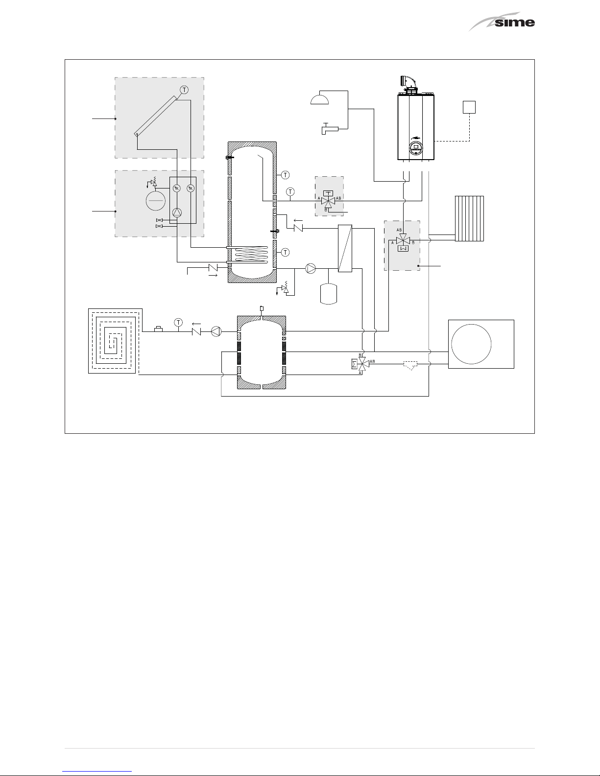
1.4.3 Open Hybrid MEM ErP base - High Temperature Kit - Solar Kit
3
2
1
LOW
TEMPERATURE
SYSTEM
PI
Vr
Vr
PS
Vs
Sp
Water
Mains
Water mains
Solar
unit
VeS
Radiator
VD
F
HEAT
PUMP
SOLAR
COLLECTOR
MU E R
SE
Vr
B2
B5
B4
B3
TS
B1
Ve
VM
VAT
PUFFER
DOMESTIC HOT WATER
STORAGE HEATER
Fig. 5
KEY
Vr
Check valve
VD
Diverter valve
Vs
Relief valve
TS
Safety thermostat (low temperature system)
PS
Domestic hot water pump
PI
System pump (low temperature)
Sp
Plate heat exchanger
Ve
Domestic hot water expansion vessel
VeS
Solar expansion vessel (optional)
VM
Domestic hot water valve (optional)
VAT
High temperature valve (optional)
B1
Domestic Hot Water High Sensor
B2
Domestic Hot Water Low Sensor
B3
Low Temperature system delivery sensor
B4
Solar Collector Sensor (supplied with the Solar Kit)
B5
DHW Inlet O-ring sensor (in boiler)
SE
External sensor
F
Y Filter (not supplied, the responsibility of the installer)
M
Delivery
R
Return
U
DHW Output
E
DHW Inlet
1
HIGH TEMPERATURE KIT
2
SOLAR KIT
3
SOLAR PANEL

12
1.5 Sensors
The sensors installed have the following characteristics:
– B1 - Domestic Hot Water Storage Tank High Sensor NTC
R25°C; 10kΩ
– B2 - Domestic Hot Water Storage Tank Low Sensor NTC
R25°C; 10kΩ
– B3 - Low Temperature system delivery sensor NTC R25°C;
10kΩ
– B4 - Solar Collector Sensor (supplied with the Solar Kit)
PT1000
– B5 -DHW Inlet O-ring sensor (in boiler) NTC R25°C; 10kΩ
– SE - External sensor NTC R25°C; 10kΩ
Correspondence of Temperature Detected/Resistance
Examples of reading:
TR=75°C → R=1925Ω
TR=80°C → R=1669Ω
TR
0°C 1°C 2°C 3°C 4°C 5°C 6°C 7°C 8°C 9°C
Resistenza R (
Ω)
0°C
27279
17959
12090
8313
5828
4161
3021
2229
1669
1266
973
26135
17245
11634
8016
5630
4026
2928
2164
1622
1232
25044
16563
11199
7731
5440
3897
2839
2101
1577
1199
24004
15912
10781
7458
5258
3773
2753
2040
1534
1168
23014
15289
10382
7196
5082
3653
2669
1982
1491
1137
22069
14694
9999
6944
4913
3538
2589
1925
1451
1108
21168
14126
9633
6702
4751
3426
2512
1870
1411
1079
20309
13582
9281
6470
4595
3319
2437
1817
1373
1051
19489
13062
8945
6247
4444
3216
2365
1766
1336
1024
18706
12565
8622
6033
4300
3116
2296
1717
1300
998
10°C
20°C
30°C
40°C
50°C
60°C
70°C
80°C
90°C
100°C
1.6 Expansion vessels
The expansion vessel installed on the boilers has the following
characteristics:
Expansion vessel
Capacity (l)
Prefilling
(kpa) (bar)
in boiler
9 100 1
domestic hot water
8 300 3
solar
12 250 2.5
(*) Conditions of:
Average maximum temperature of the system 85°C
Start temperature at system filling 10°C.
m
WARNING
– The difference in height between the relief valve
and the highest point of the system cannot exceed
6 metres. If the difference is greater than 6 metres,
increase the prefilling pressure of the expansion
vessel and the system when cold by 0.1 bar for each
meter increase.
1.7 Circulation pump
The flow-head performance curve for the pumps used in the Open
Hybrid MEM ErP Systems are indicated in the following graphs:
1.7.1 High temperature system pump
RESIDUAL HEAD (mbar)
0
0 800 1000 1200600400200
100
200
300
400
500
600
30
25
35
FLOW (l/h)
Fig. 5
1.7.2 Low temperature system pump
Flow-head-Performance Diagram (Pump at max speed and
∆p constant).
0
0 800 1000 1200 1400 1600
1800
600400200
100
200
300
400
500
RESIDUAL HEAD (mbar)
FLOW (l/h)
600
700
800
Fig. 6
1.7.3 Pump equipped with LED
LED
Fig. 7

13
Brava Slim HE 35 ErP
boilers use the pump equipped with LED
warning lights which indicate:
LED colour Status Trouble-shooting
LED off No electrical power
Green
Permanently
on
Normal operation
Red/Green Flashing
"Transient safety shutdown"
Anomaly in progress
Red Flashing Permanent safety shutdown
For the “Any pump faults and possible solutions“ see the rel-
evant section at the end of the manual.
1.8 Mem Remote Control
The MEM Remote Control manages the entire system
OPEN HYBRID MEM ErP.
Prg
Esc
156
Backlit display
82
31
Button Function
Alarm display (if present)
Red flashing light = alarm present
Access to parameters menu
(press and hold)
Return to previous menu or the Main screen
Scroll forwards
Confirm the selection of an item in the menu or
modification of value/data
Scroll backwards
Fig. 8
1.9 Electrical panel
To facilitate the electrical connections,it is recommended that
the panel is hooked to a clip on the domestic hot water storage tank. The panel is equipped with the following pre-cabled
components which require connection.
1
3
6
2
4
5
7
KEY
1
Control unit
2
Communication bus converter
3
Transformer
4
Power supply terminals
5
Low voltage terminals
6
High voltage terminals
7
Fuses
Fig. 9

14
1.10 Wiring diagram
BOILER
Y2
Y1
B -
A +
GNX
MOD-BUS
CONVERTOR
230V - 24V
TRANSFORMER
30VA
SP1
230V
0
230
GND
A
B
24
0
F2
T 2A
CABLE
SUPPLIED 6m
Extendable up to 50m
(RJ12 telephone cable)
24V
B4
B1
B2
B3
B5
B6
B8
ID1
GND
ID2
PE
L
N
N06
N07
N01
NA
LA
TS
MO3
MO1
12 3
LV system protection
(present in electrical panel)
CONTROL UNIT
EARTH
NODE
ELECTRICAL PANEL
FUI
T 6.3A
GND
Y2
C2
N02
N03
C3
G
G0
SYNC
SYNC
B1
B2
B3
B4
B5
B6
GND
+5Vref
+VDC
IDI
GND
CI
NCI
NOI
N04
N05
N06
N07
C3
GND
ID2
B7
B8
GND
TLAN
Y1
GNX
+
-
GND
+
-
N03
C3
N04
N05
N06
N07
C3
GND
ID2
B7
B8
OT
SE
MO2
N L N L
PE
N L
PE
M
2
3
6
M
DOMESTIC HOT WATER PUMP
LOW TEMPERATURE SYSTEM PUMP
AUTOMATIC FILLING VALVE
HEAT PUMP DIVERTER VALVE
KEY
1 Control unit
2 Mod-bus converter
3 Transformer
MO1/3
Electrical panel terminal board
OT OpenTherm Connection
B1 Domestic Hot Water High Sensor
B2 Domestic Hot Water Low Sensor
B3 Low Temperature system delivery sensor
B4 Solar Collector Sensor
B5 DHW Inlet O-ring sensor in boiler

15
Electrical wiring diagram
NANO1
NALA
NALA
LA
NA
L
N
NANO6
PE
PE
PE PE
GND
GND
GND
GND
GND
NANO7
ELECTRICAL PANEL TERMINAL BOARD (Open Hybrid Mem)
MO1
GNX
2
6
3
GND
GND
BLUE
BLACK
BROWN
123456
T
BOILER TERMINAL BOARD
ID2
ID1
B6
B4
B8
24 V
Y2
Y1
B -
FU2
FU1
A +
GND
HEAT PUMP TERMINAL BOARD
N1
L1
R+
R-
GNDR
ELECTRICAL PANEL CONTROL UNIT
MEM REMOTE CONTROL
M
EXTERNAL SENSOR - OPTIONAL KIT
(cable not supplied 2x0.5mm²)
RJ12 TELEPHONE CABLE supplied as
standard L=6m extendable up to 50m
HEAT PUMP - MODBUS
(cable not supplied shielded 3x0.5mm²)
BOILER - POWER SUPPLY
(boiler output cable supplied as standard)
SOLAR PUMP - OPTIONAL KIT
(cable supplied in optional kit)
COLD MODE
(230Vac 1A max - cable not supplied 2x1.5mm²)
HIGH TEMPERATURE CIRCUIT VALVE - OPTIONAL KIT
(cable supplied in optional kit)
HIGH TEMPERATURE CIRCUIT REQUEST (*)
LOW TEMPERATURE CIRCUIT REQUEST (*)
HUMIDISTAT REQUEST (*)
MULTIFUNCTION DIGITAL INPUT (*)
SOLAR COLLECTOR SENSOR - OPTIONAL KIT (*)
L
N
PE
IG1
PE
POWER SUPPLY
230 V - 50 Hz
OT (Cable from electrical panel supplied as standard)
T
(*) cable not supplied 2x0.5mm²
ANTI-FREEZE RESISTOR - OPTIONAL KIT
(cable supplied in optional kit)
L
N
L
N
KA
MO3
MO2
N
L
PE
IG2
HEAT PUMP
POWER SUPPLY
230 V - 50 Hz

16
2 INSTALLATION
2.1 Receiving the product
The OPEN HYBRID MEM ErP systems are supplied with the
following packages:
1
2
4
3
Fig. 10
m
WARNING
Package 2 contains the Pipe Kit, the Mem Remote Control, the sensors and the insulation parts to be used after
lling.
2.2 Dimensions
Description
W
(mm)
D (mm) H (mm)
1 - Domestic Hot Water Storage Tank 370 375 2100
2 - Plumbing system kit 500 380 1235
3 - Boiler 450 280 780
4- SHP M 006 ErP heat pump
1140 375 720
4- SHP M 009 ErP heat pump
1230 370 865
4- SHP M 012 ErP heat pump 1260 450 1400
2.3 Handling
Handling of the Sime OPEN HYBRID MEM ErP system is to be
carried out with equipment which is suitable for the dimensions and weights of the parts using suitable accident prevention protection.
When handling is not carried out manually, operators must ensure
that the maximum weight per person is not exceeded.
a
DANGER
Use suitable tools and accident prevention protection when removing the packaging and when handling the appliance.
d
IT IS FORBIDDEN
Do not leave packaging material around or near
children since it could be dangerous. Dispose of it as
prescribed by legislation in force.
2.4 Installation of the Open Hybrid Mem ErP
System
The OPEN HYBRID MEM ErP system is to be assembled in the
following sequence:
– Domestic hot water storage tank
– Boiler
– Plumbing system kit
INSTALLATION OF THE DOMESTIC HOT WATER STORAGE TANK
Lift the domestic hot water storage tank and hook onto the frame
bracket (A), place the upper slot on the storage tank onto the prearranged pun (B) and secure using the nut and washer supplied.
The storage tank can only be made secure when it is hooked
to the frame bracket.
A
B
C
Fig. 11
– Mount the 3/8”-3/4” reducer (supplied) on the water mains con-
nection fitting (C) using sealant or teflon to ensure tightness.

17
BOILER INSTALLATION
Position the boiler inside the built-in frame hanging it by placing the slots on the two prearranged pins. Secure using the
nuts and washers supplied.
Fig. 12
m
WARNING
The installer must ensure that a condensate outlet
pipe is fitted. The pipe must not have any siphons
or horizontal sections to prevent ice from forming if
there is condensate inside.
WATER SYSTEM KIT INSTALLATION
m
WARNING
Always place a seal on every joint and tighten the
swivel joints only when all operations have been
completed.
Premise
Check that the connections have already been fitted on the
fitting template
– Connect the pipe (1) code 6277844 (cold water inlet from
mains) to the connection (E- mains inlet) of the fitting template
and to the domestic hot water storage tank
– Connect the pipe (2) code 6277821 to the plate heat exchanger
(Sp) and rest it on the shelf (M) in the built-in frame. Connect the
pipe (2) to the domestic hot water storage tank
2
M
Sp
1
E
Fig. 13
– Mount the assembly consisting of: pipe (3) code 6277822, do-
mestic hot water pump (PS), pipe (4) code 6277823, relief valve
(Vs) and cock (Rs)
m
WARNING
– To facilitate the installation/tightening operations,
it is recommended that the assembly is connected
after having fitted the pipes.
– Fit the domestic hot water pump (PS) with the arrow
facing upwards.
3
Sp
4
Rs
Vs
PS
Fig. 14

18
– Connect the pipe (5) code 6277824 to the connection (U-Do-
mestic hot water output) of the fitting template and to the boiler connection (U-DHW output)
– Connect the pipe (6) code 6226973 to the connection (G-Gas) of
the fitting template and to the boiler connection (G-gas)
– Connect the pipe (7) code 6277832 to the connection (E-ACS
inlet) of the boiler and the domestic hot water storage tank
5
U G
7 6
Fig. 15
– Connect the pipe (8) code 6277828 to the plate heat exchanger
(Sp)
– Connect pipe (9) code 6277830 to the pipe (8) connection and
to the connection (MP- Heat Pump Delivery) of the fitting template
– Connect the pipe (10) code 6277825 to the plate heat exchang-
er (Sp) and to the diverter valve (VD)
m
WARNING
Respect the direction of the diverter valve as shown
in the figure below
VD
11
12
B A
AB
10
Fig. 16
– Connect the pipe (11) code 6277827 to the
diverter valve (VD)
– Connect the pipe (12) code 6277826 to the diverter valve (VD)
and to the connection (RP-Heat Pump Return)
Rp
Mp
8
10
12
11
VD
9
Fig. 17
 Loading...