

Sime Open Hybrid MEM 30-009, Open Hybrid MEM 25-009, Open Hybrid MEM 35-006, Open Hybrid MEM 30-006, Open Hybrid MEM 35-009 Installation And Maintenance Manual
...
Fonderie SIME S.p.A.
6322912 - 03/2016 - R3
INSTALLATION AND MAINTENANCE MANUAL
OPEN HYBRID MEM ErP
Dear Customer,
Thank you for purchasing an
Open Hybrid MEM ErP
system, a last generation appliance, with all the technical and performance
features to satisfy your needs for heating and the supply of domestic hot water, in maximum safety and with low running costs.
We recommend that your new appliance is started up within 30 days from the date of installation by qualified technicians,
so that you can benefit from both the legal warranty and the conventional warranty provided by
Sime
which is to be found
at the end of this manual.
EN

2
RANGE
MODEL CODE
Open Hybrid MEM 25-006 8114400
Open Hybrid MEM 25-009 8114401
Open Hybrid MEM 25-012 8114402
Open Hybrid MEM 30-006 8114403
Open Hybrid MEM 30-009 8114404
Open Hybrid MEM 30-012 8114405
Open Hybrid MEM 35-006 8114406
Open Hybrid MEM 35-009 8114407
Open Hybrid MEM 35-012 8114408
Open Hybrid MEM 25-006 S 8114409
Open Hybrid MEM 25-009 S 8114410
Open Hybrid MEM 25-012 S 8114411
Open Hybrid MEM 30-006 S 8114412
Open Hybrid MEM 30-009 S 8114413
Open Hybrid MEM 30-012 S 8114414
Open Hybrid MEM 35-006 S 8114415
Open Hybrid MEM 35-009 S 8114416
Open Hybrid MEM 35-012 S 8114417
COMPLIANCE
Our company declares that
OPEN HYBRID MEM ErP
systems
comply with the following directives:
– Gas Appliances Directive 2009/142/EC
– Low Voltage Directive 2006/95/EC
– Electromagnetic Compatibility Directive 2004/108/EC
– Ecodesign Directive 2009/125/EC
– Regulation (UE) N. 811/2013 - 813/2013
SYMBOLS
a
DANGER
To indicate actions which, if not carried out correctly,
can result in injury of a general nature or may damage or cause the appliance to malfunction; these
actions therefore require particular caution and adequate preparation.
f
DANGER
To indicate actions which, if not carried out correctly, could lead to injury of an electrical nature; these
actions therefore require particular caution and adequate preparation.
d
IT IS FORBIDDEN
To indicate actions which MUST NOT BE carried out.
m
WARNING
To indicate particularly important and useful information.
TABLE OF CONTENTS
1 SYSTEM DESCRIPTION 4
1.1 Operation ......................................5
1.1.1 Domestic hot water . . . . . . . . . . . . . . . . . . . . 5
1.1.2 Heating .............................. 5
1.1.3 Cooling .............................. 6
1.1.4 Anti-freeze function .................... 6
1.1.5 Anti-blocking function .................. 6
1.1.6 Photovoltaic function ................... 6
1.1.7 Automatic filling function ............... 6
1.1.8 Automatic degassing function ........... 6
1.2 Structure ......................................7
1.3 Technical data ..................................8
1.3.1 Boiler ................................ 8
1.3.2 Heat pump............................ 9
1.4 Main water circuits .............................10
1.4.1 Open Hybrid MEM ErP base............. 10
1.4.2 Open Hybrid MEM ErP base - High
Temperature kit....................... 10
1.4.3 Open Hybrid MEM ErP base - High
Temperature Kit - Solar Kit ............. 11
1.5 Sensors.......................................12
1.6 Expansion vessels ..............................12
1.7 Circulation pump ..............................12
1.7.1 High temperature system pump ......... 12
1.7.2 Low temperature system pump.......... 12
1.7.3 Pump equipped with LED............... 12
1.8 Mem Remote Control ...........................13
1.9 Electrical panel ................................13
1.10 Wiring diagram ................................14
2 INSTALLATION 16
2.1 Receiving the product ...........................16
2.2 Dimensions ...................................16
2.3 Handling ......................................16
2.4 Installation of the Open Hybrid Mem ErP System ....16
2.4.1 Heat pump installation................. 20
2.5 Smoke outlet and combustion air inlet .............21
2.5.1 Openings in the frame to allow the passage
of the smoke outlet.................... 21
2.5.2 Separate ducts (Ø 60/100mm) ........... 22
2.5.3 Separate ducts (Ø 60mm and Ø 80mm) ... 22
2.6 Mem Remote Control Installation .................23
2.7 Solar thermal storage tank connections............23
2.8 Position of the sensors . . . . . . . . . . . . . . . . . . . . . . . . . . 24
2.9 Electrical connections...........................25
2.9.1 Connection to the mains ............... 25
2.9.2 Component connections................ 25
2.9.3 Boiler connections .................... 25
2.10 Filling operations...............................26
2.10.1 Automatic degassing function ........... 27
2.10.2 Setting boiler parameters .............. 27
2.11 Emptying operations ............................28
3 COMMISSIONING 29
3.1 Preliminary operations ..........................29
3.2 Commissioning ................................29
3.3 Parameter setting and display ....................30
3.4 Complete list of parameters......................31
3.5 Parameter functions ............................34
3.5.1 General settings ...................... 34
3.5.2 Generation System Settings............. 35
3.5.3 Input and Output Configuration .......... 37
3.5.4 Heating ............................. 38
3.5.5 Cooling.............................. 40
3.5.6 DHW................................ 41
3.5.7 Energy Settings....................... 42
3.5.8 Communication....................... 43
4 MAINTENANCE 44
4.1 Adjustments...................................44
4.2 Alarms .......................................44
4.3 Any pump faults and possible solutions ............46
4.4 Alarm log .....................................46
5 APPLICATION DIAGRAMS 47
6 PRODUCT DATA SHEET 55

3
SAFETY WARNINGS AND REGULATIONS
m
WARNINGS
– After having removed the packaging make sure
that the product supplied is integral and complete
in all its parts. If this is not the case, please contact the Dealer who sold the appliance.
– The appliance must be used as intended by
Sime
who is not responsible for any damage caused to
persons, animals or things, improper installation,
adjustment, maintenance and improper use of the
appliance.
– In the event of water leaks, disconnect the appli-
ance from the mains power supply, close the water
mains and promptly inform professionally qualified personnel.
– Periodically check that the operating pressure of
the water heating system when cold is
1,0-1,2 bar
.
If this is not the case, increase the pressure or
contact professionally qualified personnel.
– If the appliance is not used for a long period of
time,
ONLY WHEN THERE IS THE RISK OF FREEZING
,
at least one of the following operations must be
carried out:
-
set the main system switch to "OFF";
-
close the gas and water valves for the water
heating system.
– If there is the risk of freezing, leave the gas valves
open and ensure the appliance is connected to the
mains power. This way the anti-freeze function will
remain active if set appropriately.
– In order to ensure optimal appliance operations
Sime
recommends that maintenance and checks
are carried out
ONCE A YEAR.
m
WARNINGS
–
It is recommended that all operators
read this manual carefully in order to use the appliance in a safe
and rational manner.
–
This manual
is an integral part of the appliance. It
must therefore be kept for future reference and
must always accompany the appliance in the event
the appliance is transferred or sold to another
Owner or User or is installed on another system.
–
Installation and maintenance
of this appliance must
be carried out by a qualified company or by a professionally qualified technician in accordance with
the instructions contained in the manual. The
company or technician will, at the end of installation operations, issue a statement of compliance
with national and local Technical Standards and
Legislation in force
RESTRICTIONS
d
IT IS FORBIDDEN
– The appliance is not to be used by children or un-
assisted disabled persons.
– Do not use electrical devices or appliances such as
switches, electrical appliances etc if you can smell
fuel. If this should happen:
-
open the doors and windows to air the room;
-
close the gas isolation device;
-
promptly call for professional assistance.
– Do not touch the appliance with bare feet or with
any wet part of the body.
– Do not carry out any technical intervention or
cleaning operation before having disconnected
the appliance from the mains power by setting the
main switch to "OFF", and closing the gas supply.
– Do not modify the safety or adjustment devices
without authorization and instructions from the
manufacturer.
– Do not block the condensate drain (if present).
– Do not pull, detach or twist the electrical cables
coming out of the appliance even if the appliance is
disconnected from the mains power supply.
– Do not block or reduce the size of the ventilation
openings of the room where the appliance is in-
stalled, if present.
– Remove the mains power and gas supply from the
appliance if the external temperature could fall
below ZERO (risk of freezing).
– Do not leave containers with flammable substanc-
es in the room where the appliance is installed.
– Do not leave packaging material around since it
could be dangerous. Therefore dispose of it as pre-
scribed by legislation in force.

4
1 SYSTEM DESCRIPTION
OPEN HYBRID MEM ErP systems are built-in, “modular” systems for heating and cooling rooms and for the production of
domestic hot water. They can be "assembled" on the basis of
the system needs requested by the customer.
The basic OPEN HYBRID MEM ErP structure consists of:
– Enclosure frame, fully recessed for outdoors, or in cabinet
for indoors. This must be ordered and installed before the
"components" are requested.
– Basic appliances/components (to be installed inside the
built-in housing structure):
– Hot water storage tank in stainless steel with a capacity
of 150 litres.
– 25, 30 or 35 kW hot water on-demand condensing boiler
– Main electrical panel.
– 8 litre hot water expansion vessel
– Relief valve and pump.
– Pipes for connecting all the appliances which make up
the system.
– A bag containing nuts, bolts and screws, the technical
data plate and the assembly instructions.
– Single column solar panel assembly complete with all the
water circuit elements needed for operating a solar ther-
mal circuit if installed (optional).
– Thermostatic mixer (optional)
– 12 litre solar thermal expansion vessel (optional)
Additional appliances/devices to complete the basic/minimum structure:
– Sime SHP M ErP heat pump to be selected on the basis of
system requirements
– MRM Remote Control to manage the entire system.
In the basic configuration, OPEN HYBRID MEM ErP systems
provide hot water at a maximum delivery temperature of 60°C
and return temperature of 50°C, but they can also be integrated with the following optional kits:
– High temperature kit: to manage system terminals such as
radiators, fan convectors.
– Solar kit: to use the SIMESOL 182 solar panel to produce
domestic hot water maximising the use of alternative energy and limiting boiler usage.
m
WARNING
– With this appliance the USE OF THE EXTERNAL
SENSOR IS COMPULSORY for the boiler to work
with a sliding temperature (delivery temperature
varies automatically on the basis of the external
temperature detected), for the activation of the an
ti-freeze function and to calculate the convenience
of the ener
gy sour
ces.
– Commissioning of the OPEN HYBRID MEM
ErP system must be carried out by qualified
technicians.
Fig. 1

5
1.1 Operation
1.1.1 Domestic hot water
The 150 litre hot water storage tank in STAINLESS STEEL is
made exclusively from renewable sources with the following
priorities:
1
Solar Thermal Energy (if present);
2
Heat pump.
The domestic hot water prepared in the storage tank always
remains in the boiler before being used. The boiler burner is
activated by the MEM only if the inlet temperature does not
reach the setpoint set by the user.
– Weekly programming from the MEM display for the prepa-
ration of the domestic hot water and therefore of the storage tank.
– The solar thermal system (if present) can prepare the 150
litres of hot water in the storage tank at the maximum temperature of 90°C. The actual energy ratio depends on the
solar rays which the solar collector is subject to. The solar
thermal pump is managed by the MEM on the basis of the
storage tank-collector and implements the ANTI-FREEZE
COLLECTOR, COOLING COLLECTOR).
– The heat pump can prepare 150 litres of hot water in the
storage tank up to the maximum temperature of 50°C.
Preparation by the heat pump only occurs in periods in
COMFORT mode. To allow for preparation when also in REDUCED mode, act on the specific parameter.
– The amply dimensioned plate heat exchanger allows the
heat pump to operate with high COP values also for the
preparation of domestic hot water in addition to reduced
restore times. Management by the MEM includes activation
of the heat pump only when the storage tank is almost completely depleted of hot water in order to reduce the number
of start-ups to a minimum and to allow the heat pump to
operate at low temperatures (high COP).
– The actual preparation temperature of the storage tank by
the heat pump is calculated dynamically by the MEM on the
basis of the efficiency conditions (external temperature +
delivery temperature).
– The MEM manages the heat pump domestic hot water pri-
ority on the basis of some modifiable parameters:
– Priority in the summer (COOLING or DOMESTIC HOT WATER
with maximum time to be set). Default priority COOLING
– Priority in the winter (HEATING or DOMESTIC HOT WATER
with maximum time to be set). Default priority DOMESTIC
HOT WATER for no more than 30 minutes.
– The ANTI-LEGIONELLA function, if enabled, includes prepa-
ration of the storage tank at a temperature of 55°C (maintained for approximately 2 hours) once a week for bacteria
sanitisation.
1.1.2 Heating
– The heating request is made by means of the dry contact
(for example, a safety limit microswitch, etc..).
– The medium-low temperature heating circuit can reach a
maximum delivery temperature of 55°C with only the heat
pump operating. It is possible to reach a temperature of
60°C (return 50°C) with the combined heat pump - boiler
operation.
– The 30 litre inertial storage tank acts as a thermal flywheel
(needed by the heat pump) and hydraulic separator allowing operation with any flow rate processed by the system.
Thanks to the specific design, the inertial tank always guarantees the best possible working conditions for the heat
pump making it work at the minimum temperature made
available by the system (no mixing of the return water inside
the inertial storage tank).
– The delivery setpoint can be set by the user at a fixed value
or it can be calculated dynamically by the MEM on the basis
of the external temperature and the selected climatic curve.
– System safety thermostat (50°C fixed calibration with the
option of deactivating the parameter) to protect the radiating system at low temperatures.
– In every operating condition, the MEM control unit calcu-
lates the heat pump COP (external temperature + delivery
temperature) and therefore whether the boiler or the heat
pump is most appropriate and it controls the subsequent
activation. If the most appropriate source is not sufficient to
cover the system needs, the other source can be activated
at the same time for the minimum energy needed to reach
the setpoint (this function can be set by the specific parameters). This way AND (simultaneous) operation is possible of
the sources allowing the heat pump to be activated even in
conditions in which it would normally be switched off as the
power output is less than the system requirements.
– The power modulation of the heat pump and the boiler is
always controlled by the MEM at the minimum level necessary to meet the set system setpoint (there is no increase in
the generator setpoint in relation to the system if not necessary).
– The defrost function of the heat pump is controlled by the MEM
eliminating almost all temporary comfort loss and compensating the energy withdrawn from the system or the boiler.
– Using the MEM parameters, it is possible to set gas and
electrical energy costs to allow the dynamic calculation of
the financial advantage of using each individual source. If
this data is not available, the energy convenience will still
be calculated (primary energy equivalence).
– The high efficiency and high flow-head modulating pump
is able to guarantee the necessary flow rate to the system
adjusting the number of revolutions (and therefore the consumption) on the basis of the instantaneous absorbed power of the system.
– Option of installing a HIGH TEMPERATURE KIT for an addi-
tional heating circuit with delivery temperature up to 80°C.
This circuit is used exclusively by the boiler as the temperatures are too high for the heat pump to operate. If the request is made for the boiler to operate together with the
high and low temperature circuits, the boiler generates with
a high temperature setpoint while the low-temperature circuit is adjusted by means of a distribution valve before mixing inside the puffer to obtain the set temperature.

6
1.1.3 Cooling
– Setting the summer mode (cooling) from the remote display
or remote contact (option of installing a summer/winter selector for the user's convenience - not supplied).
– The cooling request is made by means of the dry contact (for
example, a safety limit microswitch, etc..).
– Heat pump operation only in cool mode.
– Fixed system setpoint set by the user.
– Humidistat input (dry contact) for a second setpoint which
can be set by the installer for dehumidification (reduction)
or to prevent the formation of condensate in the radiating
system (increase).
– The power modulation of the heat pump is always controlled
by the MEM at the minimum level necessary to meet the set
system setpoint (there is no reduction in the heat pump setpoint in relation to the system if not necessary).
– 30 litre puffer and pipes with insulation present. The install-
er must complete the insulation of the connection points as
indicated in the installation manual.
1.1.4 Anti-freeze function
– Protection activated by the MEM with activation of the pumps,
valves and generators on the basis of the temperatures detected by the sensors (electrical power is required). It is essential that there is a correctly installed external sensor.
1.1.5 Anti-blocking function
– Function controlled by the MEM with the activation of all the
active organs after a period of inactivity to prevent blocking
(electrical power is required).
1.1.6 Photovoltaic function
– Function managed by the MEM to increase the amount of
auto-consumption of the electrical energy produced by a
photovoltaic system if installed.
1.1.7 Automatic filling function
– If system pressure drops with the subsequent intervention
of the low pressure alarm, it is possible to refill simply be
pressing a button on the display.
1.1.8 Automatic degassing function
– Function to be activated by the installer or technical per-
sonnel to allow rapid degassing of the air inside the system
during commissioning
– In any case, the system must be made according to the di-
agrams present in the installation manual and goose-neck
fittings are to be avoided.
– If they cannot be avoided, the installer must ensure that
there are bleed devices in the top sections.

7
1.2 Structure
1
2
6
5
4
3
8
7
9
18
15
20
21
19
16
14
13
12
11
10
17
Fig. 2
KEY
1
150 litre domestic hot water storage tank
2
Plate heat exchanger (Sp)
3
Sensor socket
B1
4
Sensor
B5
5
Diverter valve (VD)
6
Domestic hot water pump (PS)
7
Domestic hot water expansion vessel (Ve)
8
Sensor socket
B2
9
Domestic hot water storage tank drain valve
(
Rs
)
10
Domestic hot water relief valve (Vs)
11
Sensor
B3
12
System safety thermostat (TS)
13
Check valve (Vr)
14
Low temperature system pump
(PI)
15
Inertial puffer
16
Automatic filling
(EV)
17
Electrical panel
18
Condensation boiler
19
Mem Remote control
20
External sensor (SE)
21
Sime SHP M ErP heat pump

8
1.3 Technical data
1.3.1 Boiler
DESCRIPTION
Brava Slim HE ErP
25 30 35
CERTIFICATIONS
Country of intended installation
IT – ES – PT – GR – SI
Fuel
G20 / G31
PIN number
1312CP5936
Category
II2H3P
Appliance classification
B23P - B33P - B53P - C13 - C33 - C43 - C53 - C63 - C83
Class NOx
5 (< 70 mg/kWh)
HEATING PERFORMANCE
HEAT INPUT (*)
Nominal flow (Q
n max)
kW 20 24 30
Minimum flow (Qnw min)
kW 4 4,8 6
HEAT OUTPUT
Nominal (80-60°C) (P
n max)
kW 19,7 23,6 29,5
Nominal (50-30°C) (Pn max)
kW 21,4 25,7 32,2
Minimum G20 (80-60°C) (Pn min)
kW 3,9 4,7 5,9
Minimum G20 (50-30°C) (Pn min)
kW 4,3 5,1 6,5
Minimum G31 (80-60°C) (Pn min)
kW 3,9 4,7 5,9
Minimum G31 (50-30°C) (Pn min)
kW 4,3 5,1 6,5
EFFICIENCY
Max useful efficiency (80-60°C)
% 98,5 98,3 98,3
Min useful efficiency (80-60°C)
% 97,5 97,9 98,3
Max useful efficiency (50-30°C)
% 107 107,1 107,3
Min useful efficiency (50-30°C)
% 107,5 106,3 108,3
Useful efficiency at 30% of load (40-30°C)
% 107,0 107,0 107,0
Thermal efficiency (EEC 92/42)
Losses after shutdown at 50°C
W 84 88 88
DOMESTIC HOT WATER PERFORMANCE
Nominal heat input (Q
nw max)
kW 24 28 34,8
Minimum heat input (Qnw min)
kW 4 4,8 6
Specific D.H.W. flow rate ∆t 30°C (EN 13203)
l/min 11,2 12,9 16,5
Continuous D.H.W. flow rate (∆t 25°C / ∆t 35°C)
l/min 13,6 / 9,7 16,1 / 11,5 20 / 14,3
Minimum D.H.W. flow rate
l/min 2 2 2
Max (PMW) / Min Pressure
bar 7 / 0,5 7 / 0,5 7 / 0,5
kpa 700 / 50 700 / 50 700 / 50
ENERGY PERFORMANCE
HEATING
Heating seasonal energy efficiency class
A A A
Heating seasonal energy efficiency
% 91 91 91
Sound power
db(A) 54 56 53
DOMESTIC HOT WATER
Domestic hot water energy efficiency class
A A A
Domestic hot water energy efficiency
% 82 80 80
Stated domestic hot water profile load
XL XL XL
ELECTRICAL SPECIFICATIONS
Power supply voltage
V 230
Frequency
Hz 50
Absorbed electrical power (Qn max)
W 70 85 92
Absorbed electrical power at (Qn min)
W 52 52 57
Absorbed electrical power in stand-by
W 3,6 3,6 3,6
Electrical protection degree
IP X5D
COMBUSTION DATA
Smoke temperature at Max/Min flow (80-60°C)
°C 82 / 66 89 / 71 77 / 67
Smoke temperature at Max/Min flow (50-30°C)
°C 59 / 45 71 / 51 58 / 49
Maximum smoke flow Min/Max
g/s 11,2 / 1,9 13,1 / 2,2 16,3 / 2,8
CO2 at Max/Min flow rate (G20)
% 9,0 / 9,0 9,0 / 9,0 9,0 / 9,0
CO2 at Max/Min flow rate (G31)
% 10,0 /10,0 10,0 /10,0 10,0 / 10,0
NOx measured
mg/kWh 39 41 37
NOZZLES GAS
Number of nozzles
No. 1 1 1
Nozzle diameter (G20-G31)
mm 5,3 5,3 5,3
Gas consumption at Max/Min flow rate (G20)
m3/h 2,53 / 0,42 2,96 / 0,50 3,70 / 0,63
Gas consumption at Max/Min flow rate (G31)
Kg/h 1,86 / 0,31 2,17 / 0,37 2,71 / 0,46
Gas supply pressure (G20/G31)
mbar 20 / 37 20 / 37 20 / 37
kpa 2 / 3,7 2 / 3,7 2 / 3,7
TEMPERATURE PRESSURE
Max operating temperature (T max)
°C 85
Heating adjustment range
°C 20÷80
Domestic hot water adjustment range
°C 10÷60

9
DESCRIPTION
Brava Slim HE ErP
25 30 35
Max operating pressure (PMS)
bar 3
kpa 300
Water content in boiler
l 4,65 4,75 4,95
Lower Heat Output (Hi)
G20 Hi.
9,45 kW/m3 (15°C, 1013 mbar) -
G31 Hi.
12,87 kW/kg (15°C, 1013 mbar)
1.3.2 Heat pump
DESCRIPTION
SHP M ErP
006 009 012
ELECTRICAL SPECIFICATIONS
Power supply 230V/1/50Hz 230V/1/50Hz 230V/1/50Hz
Maximum absorbed power kW 2,81 4,61 5,78
Maximum inrush current A 7,9 13,0 16,4
Maximum absorbed current A 12,3 20,2 25,4
COOLING
Cooling capacity (1) kW
3,88
6,10 7,71
Absorbed power (1) kW 1,34 2,10 2,65
E.E.R. (1) W/W 2,90 2,91 2,91
Cooling capacity (2) kW
5,46
8,52 11,8
Absorbed power (2) kW 1,51 2,36 3,11
E.E.R. (2) W/W 3,62 3,61 3,80
HEATING
Heat Output (3) kW
5,40
8,30 11,63
Absorbed power (3) kW 1,69 2,59 3,64
C.O.P. (3) W/W 3,20 3,20 3,20
Heat Output (4) kW
5,65
8,88 12,28
Absorbed power (4) kW 1,40 2,19 3,02
C.O.P. (4) W/W 4,05 4,05 4,06
COMPRESSOR
Type Rotary DC Inverter Rotary DC Inverter Twin Rotary DC Inverter
Number 1 1 2
Absorbed power while cooling (1) kW 1,25 2,16 2,59
Absorbed power while cooling (2) kW 1,21 2,10 2,73
Absorbed power while heating (3) kW 1,36 2,26 2,44
Absorbed power while heating (4) kW 1,18 2,00 2,90
Coolant oil (type, quantity) mL ESTER OIL VG74, 480 ESTER OIL VG74, 820 FV50S, 1070
FAN MOTOR
Type DC Brushless Motor DC Brushless Motor DC Brushless Motor
Number 1 1 2
Nominal absorbed power kW 0,156 0,188 2 x 0,18
Nominal absorbed current A 0,48 0,57 2 x 0,55
Speed r/min 900 900 1000
Maximum air flow rate m
3
/s 1,08 1,63 2,42
COOLANT
Type R410A R410A R410A
Coolant quantity kg 1,55 2,10 3,65
Project pressure (high / low) MPa 4,2 / 1,5 4,2 / 1,5 4,2 / 1,5
WATER CIRCUIT
Water flow rate (4) L/s 0,29 0,45 0,59
Useful flow-head (4) kPa 43 29 51
Pump nominal power (4) kW 0,094 0,102 0,125
Pump maximum power kW 0,124 0,124 0,165
Pump maximum absorbed current A 0,55 0,55 0,75
Expansion vessel L 2 2 2
Plumbing connections inch 1”M 1”M 1”M
Minimum water volume L 18 25 25
NOISE LEVEL
Sound pressure (5) dB(A) 44-50 45-53 46-54
DIMENSIONS AND WEIGHTS
Dimensions (WxHxD) mm 1134x719x373 1229x861x368 1260x1400x448
Max dimensions of package (WxHxD) mm 1310x850x430 1310x1000x430 1260x1400x448
Operating weight kg 73 92 135
Net/gross weight kg 69/77 87/96 140/153
Performance with the following conditions:
(1) Cooling: external air temperature 35°C; water temperature in/out 12/7°C.
(2) Cooling: external air temperature 35°C; water temperature in/out 23/18°C.
(3) Heating: external air temperature 7°C b.s. 6°C b.u.; water temperature in/out 40/45°C.
(4) Heating: external air temperature 7°C b.s. 6°C b.u.; water temperature in/out 30/35°C.
(5) Sound pressure level measured in free field at 1 m from the unit according to ISO 3744

10
1.4 Main water circuits
1.4.1 Open Hybrid MEM ErP base
LOW
TEMPERATURE
SYSTEM
PUFFER
PI
Vr
Vr
PSVsSp
Water mains
Water mains
DOMESTIC HOT WATER
STORAGE HEATER
VD
F
HEAT
PUMP
MU E R
SE
Vr
B2
B5
B3
TS
B1
Ve
VM
Fig. 3
1.4.2 Open Hybrid MEM ErP base - High Temperature kit
1
LOW
TEMPERATURE
SYSTEM
PI
PS
Water mains
Water mains
Radiator
VD
F
HEAT
PUMP
MU E R
SE
B2
B5
B3
TS
B1
Ve
VM
VAT
PUFFER
DOMESTIC HOT WATER
STORAGE HEATER
Vr
Vr
Vs
Sp
Vr
Fig. 4
11
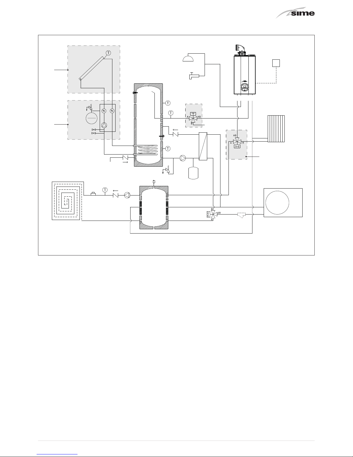
1.4.3 Open Hybrid MEM ErP base - High Temperature Kit - Solar Kit
3
2
1
LOW
TEMPERATURE
SYSTEM
PI
Vr
Vr
PS
Vs
Sp
Water
Mains
Water mains
Solar
unit
VeS
Radiator
VD
F
HEAT
PUMP
SOLAR
COLLECTOR
MU E R
SE
Vr
B2
B5
B4
B3
TS
B1
Ve
VM
VAT
PUFFER
DOMESTIC HOT WATER
STORAGE HEATER
Fig. 5
KEY
Vr
Check valve
VD
Diverter valve
Vs
Relief valve
TS
Safety thermostat (low temperature system)
PS
Domestic hot water pump
PI
System pump (low temperature)
Sp
Plate heat exchanger
Ve
Domestic hot water expansion vessel
VeS
Solar expansion vessel (optional)
VM
Domestic hot water valve (optional)
VAT
High temperature valve (optional)
B1
Domestic Hot Water High Sensor
B2
Domestic Hot Water Low Sensor
B3
Low Temperature system delivery sensor
B4
Solar Collector Sensor (supplied with the Solar Kit)
B5
DHW Inlet O-ring sensor (in boiler)
SE
External sensor
F
Y Filter (not supplied, the responsibility of the installer)
M
Delivery
R
Return
U
DHW Output
E
DHW Inlet
1
HIGH TEMPERATURE KIT
2
SOLAR KIT
3
SOLAR PANEL

12
1.5 Sensors
The sensors installed have the following characteristics:
– B1 - Domestic Hot Water Storage Tank High Sensor NTC
R25°C; 10kΩ
– B2 - Domestic Hot Water Storage Tank Low Sensor NTC
R25°C; 10kΩ
– B3 - Low Temperature system delivery sensor NTC R25°C;
10kΩ
– B4 - Solar Collector Sensor (supplied with the Solar Kit)
PT1000
– B5 -DHW Inlet O-ring sensor (in boiler) NTC R25°C; 10kΩ
– SE - External sensor NTC R25°C; 10kΩ
Correspondence of Temperature Detected/Resistance
Examples of reading:
TR=75°C → R=1925Ω
TR=80°C → R=1669Ω
TR
0°C 1°C 2°C 3°C 4°C 5°C 6°C 7°C 8°C 9°C
Resistenza R (
Ω)
0°C
27279
17959
12090
8313
5828
4161
3021
2229
1669
1266
973
26135
17245
11634
8016
5630
4026
2928
2164
1622
1232
25044
16563
11199
7731
5440
3897
2839
2101
1577
1199
24004
15912
10781
7458
5258
3773
2753
2040
1534
1168
23014
15289
10382
7196
5082
3653
2669
1982
1491
1137
22069
14694
9999
6944
4913
3538
2589
1925
1451
1108
21168
14126
9633
6702
4751
3426
2512
1870
1411
1079
20309
13582
9281
6470
4595
3319
2437
1817
1373
1051
19489
13062
8945
6247
4444
3216
2365
1766
1336
1024
18706
12565
8622
6033
4300
3116
2296
1717
1300
998
10°C
20°C
30°C
40°C
50°C
60°C
70°C
80°C
90°C
100°C
1.6 Expansion vessels
The expansion vessel installed on the boilers has the following
characteristics:
Expansion vessel
Capacity (l)
Prefilling
(kpa) (bar)
in boiler
9 100 1
domestic hot water
8 300 3
solar
12 250 2.5
(*) Conditions of:
Average maximum temperature of the system 85°C
Start temperature at system filling 10°C.
m
WARNING
– The difference in height between the relief valve
and the highest point of the system cannot exceed
6 metres. If the difference is greater than 6 metres,
increase the prefilling pressure of the expansion
vessel and the system when cold by 0.1 bar for each
meter increase.
1.7 Circulation pump
The flow-head performance curve for the pumps used in the Open
Hybrid MEM ErP Systems are indicated in the following graphs:
1.7.1 High temperature system pump
RESIDUAL HEAD (mbar)
0
0 800 1000 1200600400200
100
200
300
400
500
600
30
25
35
FLOW (l/h)
Fig. 5
1.7.2 Low temperature system pump
Flow-head-Performance Diagram (Pump at max speed and
∆p constant).
0
0 800 1000 1200 1400 1600
1800
600400200
100
200
300
400
500
RESIDUAL HEAD (mbar)
FLOW (l/h)
600
700
800
Fig. 6
1.7.3 Pump equipped with LED
LED
Fig. 7

13
Brava Slim HE 35 ErP
boilers use the pump equipped with LED
warning lights which indicate:
LED colour Status Trouble-shooting
LED off No electrical power
Green
Permanently
on
Normal operation
Red/Green Flashing
"Transient safety shutdown"
Anomaly in progress
Red Flashing Permanent safety shutdown
For the “Any pump faults and possible solutions“ see the rel-
evant section at the end of the manual.
1.8 Mem Remote Control
The MEM Remote Control manages the entire system
OPEN HYBRID MEM ErP.
Prg
Esc
156
Backlit display
82
31
Button Function
Alarm display (if present)
Red flashing light = alarm present
Access to parameters menu
(press and hold)
Return to previous menu or the Main screen
Scroll forwards
Confirm the selection of an item in the menu or
modification of value/data
Scroll backwards
Fig. 8
1.9 Electrical panel
To facilitate the electrical connections,it is recommended that
the panel is hooked to a clip on the domestic hot water storage tank. The panel is equipped with the following pre-cabled
components which require connection.
1
3
6
2
4
5
7
KEY
1
Control unit
2
Communication bus converter
3
Transformer
4
Power supply terminals
5
Low voltage terminals
6
High voltage terminals
7
Fuses
Fig. 9

14
1.10 Wiring diagram
BOILER
Y2
Y1
B -
A +
GNX
MOD-BUS
CONVERTOR
230V - 24V
TRANSFORMER
30VA
SP1
230V
0
230
GND
A
B
24
0
F2
T 2A
CABLE
SUPPLIED 6m
Extendable up to 50m
(RJ12 telephone cable)
24V
B4
B1
B2
B3
B5
B6
B8
ID1
GND
ID2
PE
L
N
N06
N07
N01
NA
LA
TS
MO3
MO1
12 3
LV system protection
(present in electrical panel)
CONTROL UNIT
EARTH
NODE
ELECTRICAL PANEL
FUI
T 6.3A
GND
Y2
C2
N02
N03
C3
G
G0
SYNC
SYNC
B1
B2
B3
B4
B5
B6
GND
+5Vref
+VDC
IDI
GND
CI
NCI
NOI
N04
N05
N06
N07
C3
GND
ID2
B7
B8
GND
TLAN
Y1
GNX
+
-
GND
+
-
N03
C3
N04
N05
N06
N07
C3
GND
ID2
B7
B8
OT
SE
MO2
N L N L
PE
N L
PE
M
2
3
6
M
DOMESTIC HOT WATER PUMP
LOW TEMPERATURE SYSTEM PUMP
AUTOMATIC FILLING VALVE
HEAT PUMP DIVERTER VALVE
KEY
1 Control unit
2 Mod-bus converter
3 Transformer
MO1/3
Electrical panel terminal board
OT OpenTherm Connection
B1 Domestic Hot Water High Sensor
B2 Domestic Hot Water Low Sensor
B3 Low Temperature system delivery sensor
B4 Solar Collector Sensor
B5 DHW Inlet O-ring sensor in boiler

15
Electrical wiring diagram
NANO1
NALA
NALA
LA
NA
L
N
NANO6
PE
PE
PE PE
GND
GND
GND
GND
GND
NANO7
ELECTRICAL PANEL TERMINAL BOARD (Open Hybrid Mem)
MO1
GNX
2
6
3
GND
GND
BLUE
BLACK
BROWN
123456
T
BOILER TERMINAL BOARD
ID2
ID1
B6
B4
B8
24 V
Y2
Y1
B -
FU2
FU1
A +
GND
HEAT PUMP TERMINAL BOARD
N1
L1
R+
R-
GNDR
ELECTRICAL PANEL CONTROL UNIT
MEM REMOTE CONTROL
M
EXTERNAL SENSOR - OPTIONAL KIT
(cable not supplied 2x0.5mm²)
RJ12 TELEPHONE CABLE supplied as
standard L=6m extendable up to 50m
HEAT PUMP - MODBUS
(cable not supplied shielded 3x0.5mm²)
BOILER - POWER SUPPLY
(boiler output cable supplied as standard)
SOLAR PUMP - OPTIONAL KIT
(cable supplied in optional kit)
COLD MODE
(230Vac 1A max - cable not supplied 2x1.5mm²)
HIGH TEMPERATURE CIRCUIT VALVE - OPTIONAL KIT
(cable supplied in optional kit)
HIGH TEMPERATURE CIRCUIT REQUEST (*)
LOW TEMPERATURE CIRCUIT REQUEST (*)
HUMIDISTAT REQUEST (*)
MULTIFUNCTION DIGITAL INPUT (*)
SOLAR COLLECTOR SENSOR - OPTIONAL KIT (*)
L
N
PE
IG1
PE
POWER SUPPLY
230 V - 50 Hz
OT (Cable from electrical panel supplied as standard)
T
(*) cable not supplied 2x0.5mm²
ANTI-FREEZE RESISTOR - OPTIONAL KIT
(cable supplied in optional kit)
L
N
L
N
KA
MO3
MO2
N
L
PE
IG2
HEAT PUMP
POWER SUPPLY
230 V - 50 Hz

16
2 INSTALLATION
2.1 Receiving the product
The OPEN HYBRID MEM ErP systems are supplied with the
following packages:
1
2
4
3
Fig. 10
m
WARNING
Package 2 contains the Pipe Kit, the Mem Remote Control, the sensors and the insulation parts to be used after
lling.
2.2 Dimensions
Description
W
(mm)
D (mm) H (mm)
1 - Domestic Hot Water Storage Tank 370 375 2100
2 - Plumbing system kit 500 380 1235
3 - Boiler 450 280 780
4- SHP M 006 ErP heat pump
1140 375 720
4- SHP M 009 ErP heat pump
1230 370 865
4- SHP M 012 ErP heat pump 1260 450 1400
2.3 Handling
Handling of the Sime OPEN HYBRID MEM ErP system is to be
carried out with equipment which is suitable for the dimensions and weights of the parts using suitable accident prevention protection.
When handling is not carried out manually, operators must ensure
that the maximum weight per person is not exceeded.
a
DANGER
Use suitable tools and accident prevention protection when removing the packaging and when handling the appliance.
d
IT IS FORBIDDEN
Do not leave packaging material around or near
children since it could be dangerous. Dispose of it as
prescribed by legislation in force.
2.4 Installation of the Open Hybrid Mem ErP
System
The OPEN HYBRID MEM ErP system is to be assembled in the
following sequence:
– Domestic hot water storage tank
– Boiler
– Plumbing system kit
INSTALLATION OF THE DOMESTIC HOT WATER STORAGE TANK
Lift the domestic hot water storage tank and hook onto the frame
bracket (A), place the upper slot on the storage tank onto the prearranged pun (B) and secure using the nut and washer supplied.
The storage tank can only be made secure when it is hooked
to the frame bracket.
A
B
C
Fig. 11
– Mount the 3/8”-3/4” reducer (supplied) on the water mains con-
nection fitting (C) using sealant or teflon to ensure tightness.

17
BOILER INSTALLATION
Position the boiler inside the built-in frame hanging it by placing the slots on the two prearranged pins. Secure using the
nuts and washers supplied.
Fig. 12
m
WARNING
The installer must ensure that a condensate outlet
pipe is fitted. The pipe must not have any siphons
or horizontal sections to prevent ice from forming if
there is condensate inside.
WATER SYSTEM KIT INSTALLATION
m
WARNING
Always place a seal on every joint and tighten the
swivel joints only when all operations have been
completed.
Premise
Check that the connections have already been fitted on the
fitting template
– Connect the pipe (1) code 6277844 (cold water inlet from
mains) to the connection (E- mains inlet) of the fitting template
and to the domestic hot water storage tank
– Connect the pipe (2) code 6277821 to the plate heat exchanger
(Sp) and rest it on the shelf (M) in the built-in frame. Connect the
pipe (2) to the domestic hot water storage tank
2
M
Sp
1
E
Fig. 13
– Mount the assembly consisting of: pipe (3) code 6277822, do-
mestic hot water pump (PS), pipe (4) code 6277823, relief valve
(Vs) and cock (Rs)
m
WARNING
– To facilitate the installation/tightening operations,
it is recommended that the assembly is connected
after having fitted the pipes.
– Fit the domestic hot water pump (PS) with the arrow
facing upwards.
3
Sp
4
Rs
Vs
PS
Fig. 14

18
– Connect the pipe (5) code 6277824 to the connection (U-Do-
mestic hot water output) of the fitting template and to the boiler connection (U-DHW output)
– Connect the pipe (6) code 6226973 to the connection (G-Gas) of
the fitting template and to the boiler connection (G-gas)
– Connect the pipe (7) code 6277832 to the connection (E-ACS
inlet) of the boiler and the domestic hot water storage tank
5
U G
7 6
Fig. 15
– Connect the pipe (8) code 6277828 to the plate heat exchanger
(Sp)
– Connect pipe (9) code 6277830 to the pipe (8) connection and
to the connection (MP- Heat Pump Delivery) of the fitting template
– Connect the pipe (10) code 6277825 to the plate heat exchang-
er (Sp) and to the diverter valve (VD)
m
WARNING
Respect the direction of the diverter valve as shown
in the figure below
VD
11
12
B A
AB
10
Fig. 16
– Connect the pipe (11) code 6277827 to the
diverter valve (VD)
– Connect the pipe (12) code 6277826 to the diverter valve (VD)
and to the connection (RP-Heat Pump Return)
Rp
Mp
8
10
12
11
VD
9
Fig. 17

19
Fit the puffer by placing the slot onto the prearranged pin, inside
the frame and secure it using the washer and nut supplied
– Connect the pipes (11) and (8) to the puffer
– Connect the pipe (13) code 6277834 to the connection (R- sys-
tem return) of the boiler and to the puffer
– Connect the pipe (14) code 6277829 to the connection (R- sys-
tem return) of the fitting template and to the puffer
R
R-caldaia
8
14
13
11
Fig. 18
– Create the assembly consisting of the pipe (15) code 6277831,
the check valve (Vr) with the arrow facing downwards, the low
temperature system pump (PI) and the pipe (16) code 6277835;
connect the assembly to the puffer and to the connection
(M-System delivery) of the fitting template
M
16
PI
Vr
15
Fig. 19

20
– Connect the pipe (17) code 6277833 to the connection (M-de-
livery) of the boiler and to the puffer
– Connect the pipe (18) code 6277848 to the connection on the
pipe (7) and to the solenoid valve (EV)
– Connect the solenoid valve (EV) to the small automatic system
filling pipe (19)
– Make sure that the check valve and the mesh filter are correctly
installed in the solenoid valve seat
18
19
7
M-caldaia
EV
17
Fig. 20
– Fit the domestic hot water expansion valve code 6245108 to the
prearranged bracket in the built-in frame and secure it using
the counternut supplied
– Connect the flexible tube code 6017401 to the domestic hot
water expansion vessel and to the connection (Z) of the pipe (3)
ensuring that the vessel, when undergoing maintenance, can
be moved without needing to be even partially drained.
– Before filling the system, close all the unused connections of the
storage tank and the pipes using the bronze plugs supplied
Z
Ve
Fig. 21
2.4.1 Heat pump installation
All models of the SHP M ErP series have been designed and
built to be installed externally and therefore the following precautions are recommended:
– observe and respect all the minimum service gaps indicated
below as this will prevent recirculation between intake and delivery which can cause the unit to perform poorly or even interrupt normal operation.
– create a floor (raised support base) suitably sized for the unit.
When the unit is operating in heating mode, the floor prevents
the formation of ice which, if allowed to accumulate, can interfere with machine operation.
– place anti-vibration supports between the base and the contact
surface even if the units are only transmitting minor vibrations
to the ground
Model
Dimensions
A B* C D E*
SHP M 006 ErP 1500 500 400 400 500
SHP M 009 ErP 1500 500 400 400 500
SHP M 012 ErP 1500 500 400 400 500
*
Recommended gaps for installation, technical assistance and
maintenance
A
D
C
B
E
Fig. 22
Plumbing connections
The plumbing connections must be carried out in compliance
with National or Local Regulations in force. The pipes must
be made in steel, galvanised steel or PVC and they must be
appropriately dimensioned on the basis of the nominal water
flow of the unit and the load losses of the water circuit. All
plumbing connections must be isolated using closed cell material which is of a suitable thickness. The Heat Pump must
be connected to the pipes using flexible joints. The following
components must be installed in the water circuit:
– Socket thermometers to detect the circuit temperature.
– Manual shutter valves to isolate the Heat Pump from the water
circuit.
– Y filter with metal link not exceeding 1 mm positioned on the
Heat Pump inlet pipe.
– Filling assembly and discharge valve where necessary.
m
WARNING
For additional and more detailed information, refer
to the manual supplied with the Heat Pump.

21
2.5 Smoke outlet and combustion air inlet
Brava Slim HE
boilers must be equipped with appropriate smoke flue ducts and combustion air inlet ducts. These ducts are consid-
ered an integral part of the boiler and are provided by
Sime
as an accessory kit, to be ordered separately from the appliance on the
basis of the type permitted and the system requirements Also refer to the manual supplied with the boiler.
2.5.1 Openings in the frame to allow the passage of the smoke outlet
The drawing indicates the positions and prearranged dimensions in the built-in frame for the outlets for the smoke outlet and
combustion air inlet pipes
280
Ø120
Ø140
Ø140
Ø140
Ø140
135
85
280
Top view
Front view Rear viewRight side view
135
85
135
85
Fig. 23
m
WARNINGS
– The smoke flue and the connection to the flue pipe must be in compliance with the national and local Standards and
Legislation in force.
– The use of rigid ducts which are resistant to temperature, condensate, mechanical stress and are air-tight is compul-
sory.
– Outlet ducts which are not isolated are a risk of danger.

22
2.5.2 Separate ducts (Ø 60/100mm)
Constructing outlets for coaxial ducts indicates the use of the
"extension" code 8093107. This is to be ordered separately and
when connected to the other accessories, from those listed in
the table below, completes the smoke-outlet/ combustion air
inlet assembly.
Extension
1
2
3
4
Fig. 24
KEY:
1
Extension
2
Air inlet
3
Smoke outlet
4
Take-off point for smoke analysis
Coaxial accessories
Description
Code
Ø 60/100 mm
Coaxial duct kit 8096250
Extension W. 1000 mm 8096150
Extension W. 500 mm 8096151
Vertical extension W. 140 mm with
smoke analysis take-off point
8086950
Adapter for Ø 80/125 mm Additional 90° curve 8095850
Additional 45° curve 8095950
Tile with joint 8091300
Roof outlet terminal W. 1284 mm 8091205
2.5.3 Separate ducts (Ø 60mm and Ø 80mm)
Constructing outlets for separate ducts indicates the use of
the "air-smoke split pipe system". This is to be ordered separately from the boiler and when connected to the other accessories, from those listed in the table below, completes the
smoke-outlet/ combustion air inlet assembly.
Split pipe system
4
2
1
3
Fig. 25
KEY:
1
Split pipe system with take-off point
2
Air inlet
3
Smoke outlet
4
Take-off point for smoke analysis
Separate accessories
Description
Code
Diameter Ø
60 (mm)
Diameter Ø
80 (mm)
Air-smoke split pipe system (without
take-off point)
8093060 -
Air-smoke split pipe system (with takeoff point)
- 8093050
90° curve M-F (6 pieces) 8089921 8077450
90° curve M-F (with take-off point) 8089924 M-F 80/60 reduction 8089923 Extension W. 1000 mm (6 pieces) 8089920 8077351
Extension W. 500 mm (6 pieces) - 8077350
Extension W. 135 mm (with take-off
point)
- 8077304
Wall outlet terminal 8089541 8089501
Internal and external ring nut kit 8091510 8091500
Inlet terminal 8089540 8089500
45° curve M-F (6 pieces) 8089922 8077451
Manifold 8091400
Tile with joint 8091300
Roof outlet terminal W. 1390 mm 8091204
Inlet/outlet fitting Ø 80/125 mm - 8091210
m
WARNING
–
The maximum total length of the ducts,
obtained by
adding the lengths of the inlet and outlet pipes,
is determined by the load losses of the individual
accessories used and
must not exceed 15 mm H2O
.

23
m
WARNING
–
For all boiler versions,
the total extension must not
in any case exceed 25 m (inlet) + 25 m (outlet) for
ducts Ø 80 mm The total extension must not exceed 6 m (inlet) + 6 m (outlet) for ducts Ø 60 mm,
even if the total load loss is less than the maximum which can be applied
2.6 Mem Remote Control Installation
Wall mounting of the Mem Remote Control requires the initial
fitting of the rear holder (A) either directly onto the wall using two expansion plugs (not supplied) or a standard 3 module
case for switches using the dome headed screws to be found
inside the packaging.
– Connect the telephone line from the electrical panel of the Pen
Hybrid Mem
– Rest the front section (B) to the rear holder and secure
everything using the countersunk screws to be found inside
the packaging
– Apply the push-on rim (C)
A
B
C
Fig. 26
m
NB.
The cable supplied with the appliance is 6 m long
and can be extended to up to 50 m with an RJ12 telephone cable.
2.7 Solar thermal storage tank connections
1
- From the plate heat exchanger
2
- Magnesium anode
3
- Socket for Sensor B2 (Domestic Hot Water Storage Tank Low)
4
- Connection for fitting 3/8”-3/4”
5
- Socket for Sensor B1 (Domestic Hot Water Storage Tank High)
6
- DHW boiler inlet
7
- Solar Delivery Kit (to Solar Assembly)
8
- Solar Return Kit (to Solar Assembly)
9
- Water mains connection
1
5
6
7
8
9
2
3
4
Fig. 27

24
2
1
3
F
Fig. 29
– Using a pointed instrument, make a hole (F) in the cable gland
suitably dimensioned for the bipolar connection cable. The cable gland must prevent any moisture from penetrating.
– Insert the bipolar connection cable into the cable gland hole (F)
which must be at the bottom of the cable gland.
– Secure the sensor (2) to the wall using the screws supplied.
– Connect the bipolar cable to the terminals (3) inside the sensor.
– Refit the cover (1) on the sensor base.
m
WARNING
– The bipolar connection cable to the sensor is not
supplied.
– It can have a maximum cross section of 1 mm,a
maximum length of 30 metres and does not need
to respect the polarity.
– It is recommended that joints are avoided, if they are
necessary, they must be watertight and suitably protected.
– Any connection cable ducts must be separated from
live cables (230V a.c.)
2.8 Position of the sensors
The sensors
B1 (Domestic Hot Water Storage Tank High
and
B2
(Domestic Hot Water Storage Tank Low)
are connected in the
factory and must only be put into the sockets prearranged on
the domestic hot water storage tank. Gently tighten the socket
safety screw without crushing the cable to prevent the sensors from detaching.
The sensors
B5 (DHW boiler inlet), B3 (Low temperature system
delivery)
and
TS (Low Temperature system Safety Thermostat)
are
supplied with the appliance and must be positioned by the installer as indicated in the figures below and be connected to
the electrical panel (see “1.10 Wiring diagram”). Make sure
that no mistake is made regarding the fast-ons of the B5 and
B3 sensors as they are similar.
TS
B3
B5
Fig. 28
The
external sensor (SE)
, supplied as standard, must be positioned on a wall of the building to be heated. This wall must be
the one which is most exposed to the wind and is NORTH or
NORTH-WEST FACING. It must be placed at 2/3 of the height
of the wall.
The socket must be secured on a
smooth
section of the wall
and where there is open brickwork or irregular walls it is be
made in an area which is as smooth as possible.
d
IT IS FORBIDDEN
To position the external sensor near doors, windows
or flue pipes or any other heat source (for example,
direct sunlight).
INSTALLATION
After having identified the installation position:
– Drill the hole for the expansion plug (5x25) supplied with the
sensor and insert the plug.
– Remove the cover (1) using a small screwdriver or by twisting
the cover but without exerting excess force.

25
2.9 Electrical connections
2.9.1 Connection to the mains
The
Open Hybrid Mem ErP
appliance and the
Heat Pump
must be
connected to the mains network
independently
in compliance
with the applicable technical Regulations and national and local legislation in force.
m
WARNING
Each connection to the mains network must:
– Use an omnipolar cut-off switch
– Disconnect switch, in compliance with EN Stand-
ards
– Respect the connections L (Live) - N (Neutral)
– Connect the earth wire to an effective earthing sys-
tem. The manufacturer is not responsible for any
damage caused by failure to earth the appliance or
failure to observe the information provided in the
wiring diagrams.
d
IT IS FORBIDDEN
To use water pipes for earthing the appliance.
2.9.2 Component connections
The
Open Hybrid Mem ErP
appliance is equipped with an electrical panel to which the following cables have been wired in
the factory:
– Low Temperature System Pump Cable (PI)
– Domestic Hot Water Pump Cable (PS)
– Heat Pump Diverter Valve Cable (VD)
– Automatic Filing Valve Cable (CA)
– Connection Cable to Mem Remote Control (RJ12)
– Low Temperature System Safety Thermostat Cable (TS)
– OpenTherm Cable (OT) to be connected to the boiler terminal
board (terminals 5 and 6)
Inputs for the electrical
connection cables
Side
Rear
Fig. 30
m
WARNING
To facilitate the electrical connections, hook the panel
to a clip on the domestic hot water storage tank.
To make the connection cables enter the inside of
the built-in frame, use the designated openings prearranged in the lower part of the frame (see
“Fig. 30”
on page 25
)
To make the connection cables enter the inside of
the panel, use the prearranged openings (1) (see
“Fig. 31” on page 25)
.
The main power cable and the boiler power cable must pass
through the PG type restricting cable glands.
The other cables must pass through the prearranged openings
which are to be appropriately drilled and must be secured using
the free cable-lock at the bottom of the electrical panel.
1
Fig. 31
2.9.3 Boiler connections
The connections to be made are:
– the electrical power connection, already connected t the
boiler, to the Open Hybrid Mem ErP electrical panel.
– the external sensor (optional) and the communication cable
(OT) to the boiler terminal board.
SE
OT
SAUX
6
5
4
3
2
1
Fig. 32
All connectors pre-cabled to the electrical panel are marked with
the symbol to identify the device which is to be connected (see
water circuit diagram).

26
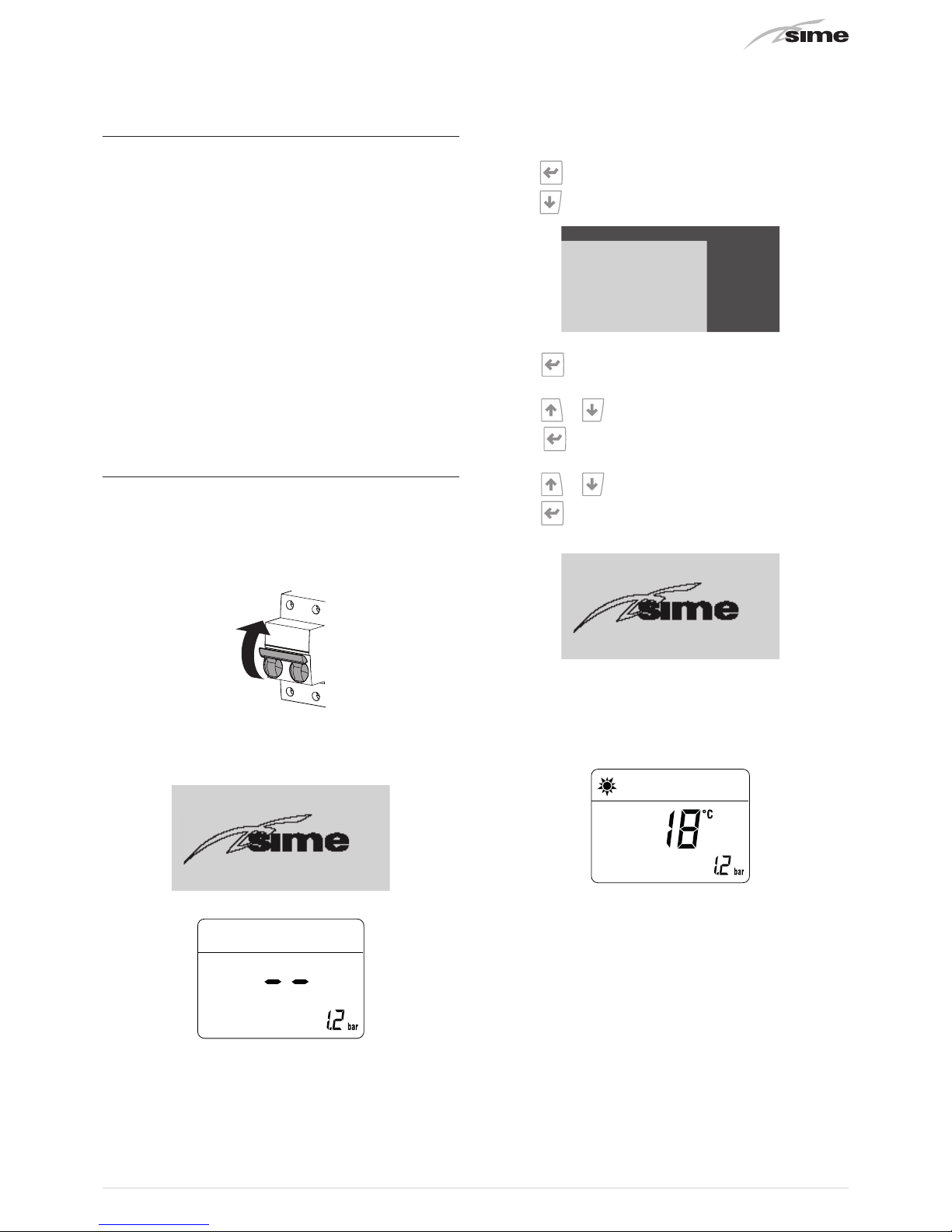
2.10 Filling operations
Filling the domestic hot water storage tank
To fill the storage tank:
– Open one or more than one hot water tap
– Open the water system isolation valve
– Wait until clean water comes out and then close them
Filling the systems
To fill the systems:
– Provide electrical power to the OPEN HYBRID MEM ErP and
the Heat Pump by setting the Main Switches IG1 and IG2 to
"ON"
ON
– The following screens will appear on the Mem Remote Con-
trol display and on the boiler display:
13:17:08 THUR 09/10/14
OPEN HYBRID MEM
– Open all the automatic bleed devices on the boiler, on the
heat pump and on the puffer
– Where possible, select the maximum pump speed (low tem-
perature system, domestic hot water system)
– Set all devices on the system to heat request (TA, etc.)
– Manually open the automatic filling valve, setting the screw
(A) to the “OPEN” position (screwdriver size 45° approximately preferably with rotation to the left and the right.)
OPEN
(45° rh or lh)
CLOSED
A
Fig. 33
NB.
The pressure in the system, visible on the boiler display for
filling purposes, should be
1.2 bar.
– Press the button on the Mem Remote Control for at-
least 5 s, until the screen appears
ENTER PASSWORD
1243
– Press to confirm and enter “password” settings. The
cursor will be on the first digit to be set.
– Press
and set (1)
– Press
to confirm and prearrange the setting for the 2nd
digit
– Press
and set (2)
– Press
to confirm
– Continue in the same way until the last digit has been con-
firmed (3).
– The
PARAMETERS MENU
screen will appear
PARAMETERS MENU
GENERAL SETTINGS
GENERATION
I/O CONFIGURATION
HEATING
COOLING
DOMESTIC HOT WATER
ENERGY SETTINGS
– Activating the Automatic Degassing Function

27
2.10.1 Automatic degassing function
To activate the Automatic Degassing Function
– Press
to select GENERATION
PARAMETERS MENU
GENERAL SETTINGS
GENERATION
I/O CONFIGURATION
HEATING
COOLING
DOMESTIC HOT WATER
ENERGY SETTINGS
– Press to confirm and enter GENERATION S202 and
to
display the screen GENERATION S203
GENERATION S203
AUTOMATIC
DEGASSING FUNCTION:
NOT ACTIVE
– Press to confirm and go into the modifiable area
– Press or and select “ACTIVE”
– Press
to confirm the modification made, start Automat-
ic Degassing.
NB.
Automatic degassing lasts 30 minutes and deactivates automatically. It can be interrupted at any moment, if necessary
by pressing the buttons
or and once again selecting
“NOT ACTIVE”. This function can be repeated a number of
times.
– Before finishing the degassing function, open the available
manual bleed valves (radiators, fan convectors, etc.)
Once the degassing function has finished
– Check on the boiler display that the system pressure is at
1.2 bar and adjust if necessary.
– Remove the heat request (TA, etc.) set previously.
2.10.2 Setting boiler parameters
To go into the parameters menu:
– from the stand-by screen press the button
y
– select the operating mode WINTER
n
– press the buttons r and t (for approximately 5 seconds)
at the same time until
“PAR 01”
(parameter number) and the
value set (0-4) appears on the display
– press the button t to scroll up through the list of parame-
ters until reaching
PAR 17
.
NB.:
pressing and holding the buttons r or t lets the user
scroll quickly.
– on reaching
PAR 17
, press the button < and set the value to
“0”
. The modifications are stored automatically.
– press the button
t
and move to
PAR 18
.
– press the button
<
and set the value to
“2”
.
– press the button t and move to
PAR 40
.
– press the button
<
and set the value to
“--”
.
–
simultaneously
, press and hold the buttons r and t for a
few seconds until the initial screen appears.

28
m
IMPORTANT
When these operations have been completed
IT IS
MANDATORY TO
:
– CHECK THE TIGHTNESS of all the joints.
– COMPLETE THE INSULATION of the pipes and
ALL the devices involved (for example, PI pump, Vr
valve, puffer bleed device, etc) using the insulation
parts supplied with the Water System Kit and spe-
cific insulation tape.
It is advisable that the pipes already supplied as insulated are completed.
2.11 Emptying operations
Emptying the domestic hot water storage tank
To empty the domestic hot water storage tank:
– Close the water system isolation valve
– Open at least one hot water tap
– Connect a pipe to the domestic hot water storage tank drain
valve (Rs) and duct it appropriately. Open the storage tank
drain valve.
– If further draining is necessary, the connection (A) of the
pipe which joins the plate heat exchanger and the water
heater can be loosened slightly.
m
WARNING
Suitably protect the devices below from any dripping
water.
Rs
A
A
Fig. 34
m
WARNING
Whenever the storage tank is drained, even partially,
the systems/circuits used by the appliance
MUST
be
refilled or reintegrated following the procedure described in the section
“2.10 Filling operations”
includ-
ing the Automatic Degassing Function.
29
3 COMMISSIONING
3.1 Preliminary operations
When the Sime
Open Hybrid Mem ErP
is commissioned, this
must be carried out by a professionally qualified technician
who, before starting the appliance, must check that:
– the type of gas used is the same as that for which the appli-
ance has been prearranged, the mains network pressure is
suitable and the duct is deaired
– the gas isolation valves for the heating system and the wa-
ter system are open
– the heat pump and boiler siphons are filled and the conden-
sate outlets are routed correctly
– the combustion air and smoke outlet ducts have been exe-
cuted correctly
– the expansion vessels are correctly prefilled
3.2 Commissioning
After having carried out the preliminary operations, perform
the following to start the Open Hybrid Mem ErP system:
– Set the main switches IG1 and IG2 to "ON"
ON
– The following screens will appear on the Mem Remote Con-
trol display and on the boiler display:
13:17:08 THUR 09/10/14
OPEN HYBRID MEM
– Check that the storage tank temperature is below 25°C.
Otherwise, open one or more than one hot water tap and
lower the temperature. Then close the taps again.
From the Mem Remote Control "Stand-by" screen:
– Press twice. The symbol n will be highlighted (flashing)
– Press twice. The symbol r will be highlighted (flashing)
13:17:08 THUR 09/10/14
COOL OFF REDUCED
n
t
r
7.3ºc
– Press to confirm the selection and go to MODIFY DHW
SETTINGS
– Press
or to select “YES”
– Press
to confirm “YES” and go to DHW OPERATING
MODE
– Press
or to select REDUCED
– Press
twice to confirm the selection and go back to the
“Stand-by” screen
13:17:08 THUR 09/10/14
OPEN HYBRID MEM
On the boiler Control Panel:
– press the button
y
once for at least 1 second to select
"SUMMER mode"
l
. the value of the delivery sensor de-
tected at that moment will appear on the display
Carry out the "Automatic self-calibrating procedure" as follows:
– press button r and set the DOMESTIC HOT WATER SET to
maximum using the button
>

30
– press and hold down the buttons < and > at the same time
for approximately 10 seconds until the flashing symbols
l
and
n
appear on the display
– as soon as the symbols begin to flash, release the buttons <
and
>
and press the button y,
within 3 seconds
– the "Automatic self-calibrating procedure" starts
–
open the hot water taps so that the ow rate is as high as possible
– the values flash on the display:
“100”
(maximum value), fol-
lowed by an "intermediate value" and finally
“00”
(minimum
value)
The operator must wait for approximately 15 minutes for the
"self-calibrating procedure" to end and the message "SUMMER mode"
l
to reappear on the display
Once this operation has been completed, close the taps
opened previously and check that the boiler shuts down.
– Press and hold the button y for at least 1 second and se-
lect "WINTER mode”
n
.
The
Open Hybrid Mem ErP
will start to operate normally.
m
WARNING
This procedure MUST ALWAYS BE CARRIED OUT
when:
– The type of gas used is changed.
– Replacing the boiler board or other components
(see the section
“4.5 Extraordinary maintenance”
in
the boiler manual).
From the Main screen, set the OPERATING MODE required by
the User.
3.3 Parameter setting and display
To go into the parameters menu from the
Main
screen on the
Mem Remote Control:
– Press and hold the button
for at least5 seconds until the
screen appears
ENTER PASSWORD
1243
– Press to confirm and enter “password” settings. The
cursor will be on the first digit to be set.
– Press
and set (1)
– Press
to confirm and prearrange the setting for the 2nd
digit
– Press
and set (2)
– Press
to confirm
– Continue in the same way until the last digit has been con-
firmed (3).
– The
PARAMETERS MENU
screen will appear
PARAMETERS MENU
GENERAL SETTINGS
GENERATION
I/O CONFIGURATION
HEATING
COOLING
DOMESTIC HOT WATER
ENERGY SETTINGS
– Press to confirm and go into the GENERAL SETTINGS
MENU
– Press
or to scroll through the screens until reach-
ing the screen required
– Press
to confirm and go into the modifiable area
– Press
or to modify the "data"
– Press
to confirm the modification
– Press
to go back to the
PARAMETERS MENU
– Press
or to select another
MENU
Continue as described above to set all the parameters listed in
the table on the following pages
NB.
Always refer to the title and number of the screen (for example,
GENERAL S100) as the number of the parameter is not always
displayed. It is data which is only used by the Mem program

31
3.4 Complete list of parameters
The parameters are divided into levels:
– U = USER
– I = INSTALLER
Use a pencil to note down the value of each modified parameter in the "Set Value" column in relation to the default value.
✎
➡
SCREEN
LEVEL
PARAMETER
DESCRIPTION DEFAULT RANGE
UNIT OF
MEASURE-
MENT
DATA TYPE
SET VALUE
1 – General Settings
S100
U 1000 Climate Control Operating Mode OFF
• OFF
• HEAT
• COOL
- I
S102
U 1010 Domestic Hot Water Operating Mode OFF
• OFF
• TIME
• COMFORT
• REDUCED
- I
S110
I 1100 Language English English - I
S112
U
- Setting Current Hour -- 00 ÷ 23 hh I
- Setting Current Minute -- 00 ÷ 59 mm I
- Setting Current Day -- 01 ÷ 31 DD I
- Setting Current Month -- 01 ÷ 12 MM I
- Setting Current Year ---- 2010 ÷ 2199 YYYY I
S114
I -
Enabling automatic switch to daylight
saving time
ENABLED
• DISABLED
• ENABLED
- D
2 – Generation System Settings
S202
I 2020 Anti-blocking function for devices ACTIVE
• NOT ACTIVE
• ACTIVE
- D
S203
I 2030 Automatic Degassing Function NOT ACTIVE
• NOT ACTIVE
• ACTIVE
- D
S207
I 2070 Automatic System Filling Function ACTIVE
• NOT ACTIVE
• ACTIVE
- D
I 2072 Filling time 5 1 ÷ 999 s I
S220
I 2200 Boiler Type
BRAVA HE
ErP
• Not included
• BRAVA HE ErP
- I
S240
I 2400 Heat Pump Type
SHP M ErP
• Not included
• SHP M ErP
- I
S248
I 2480 Priority Heat Pump Heating-DHW DHW
• HEATING
• DHW
-
I 2482
Maximum time for Heat Pump DHW
priority over heating
30 0 ÷ 500 min.
S249
I 2485 Priority Heat Pump Cooling-DHW COOLING
• COOLING
• DHW
-
I 2487
Maximum time for Heat Pump DHW
priority over cooling
30 0 ÷ 500 min.
S250
I 2500 Solar Thermal System Type Not included
• Not included
• 1-SING.COLL..
- I
S252
I 2520 ∆T ON Solar Pumps 8.0 0.0 ÷ 99.9 °C A
I 2522 ∆T OFF Solar Pumps 4.0 0.0 ÷ 99.9 °C A
S253
I 2530 Solar Pump Minimum Operating Time 20 0 ÷ 600 s I
S254
I 2540 Solar Collector Anti-freeze Function ACTIVE
• NOT ACTIVE
• ACTIVE
- D
I 2541 Solar Collector Minimum Temperature -10.0 -40.0 ÷ 10.0 °C A
S256
I 2560 Solar Collector Cooling Function ACTIVE
• NOT ACTIVE
• ACTIVE
- D
I 2561 Solar Collector Maximum Temperature 120.0 80.0 ÷ 350.0 °C A

32
Use a pencil to note down the value of each modified parameter in the "Set Value" column in relation to the default value.
✎
➡
SCREEN
LEVEL
PARAMETER
DESCRIPTION DEFAULT RANGE
UNIT OF
MEASURE-
MENT
DATA TYPE
SET VALUE
3 – Input and Output Configuration
S300
I - Analogue Input Value Display - - -
S301
I - Digital Input Status Display - - -
S302
I - Analogue Output Value Display - - -
S303
I - Digital Output Status Display - - -
S310
I 3100 External Sensor Connection
FROM
BOILER
• NOT INCLUDED
• FROM BOILER
• From Heat Pump
- I
S350
I 3500 B6 Digital input function
COOL
MODE
• NONE
• COOL MODE
• ELECTRICAL CONVENIENCE
- I
S370
I 3700 NO6 Digital output function
COOL
MODE
• NONE
• COOL MODE
• ALARM SIGNALLING
- I
4 – Heating
S400
I 4001
Low Temperature Circuit Adjustment
Type
CLIMATIC
CURVE
• FIXED SETPOINT
• CLIMATIC CURVE
-
S402
U 4020 Low Temperature Circuit Fixed setpoint 40.0 20.0 ÷ 80.0 °C A
S404
U 4040
Setpoint for Low Temperature Circuit
Nominal Ambient Temperature
20.0 5.0 - 30.0 °C A
I 4043 Low Temperature Circuit Heating Curve 1.0 0.2 - 2.2 - A
I 4044
Low Temperature Circuit Heating Curve
Transfer
0.0 -15.0 - 15.0 °C A
I 4045
Low Temperature Circuit Heating Curve
Rotation
0.0 -15.0 - 15.0 °C A
S406
I 4060
Minimum Setpoint for Low Temperature
Circuit Heating System
20.0 10.0 - 60.0 °C A
I 4062
Maximum Setpoint for Low Temperature
Circuit Heating System
45.0 10.0 - 60.0 °C A
I 4066
50°C Low Temperature Circuit Safety
Thermostat
ENABLED
• DISABLED
• ENABLED
-
S409
I 4090 Building cladding Inertia-Delay 4
• 0
• 4
• 8
• 12
• 24
h I
S414
I 4140
High Temperature Heating Circuit
Included
NO
• NO
• YES
- D
S415
I 4150 High Temperature Circuit Fixed Setpoint 65.0 20.0 ÷ 80.0 °C A
S417
I 4170 High Temperature Circuit Priority OFF
• OFF
• ON
-
S426
I 4260 Enabling Heating Aid ON
• OFF
• ON
- D
I 4262 Delay Heating Aid 30 0 ÷ 999 min. I
5 – Cooling
S500
U 5000 Cooling System Fixed Setpoint 15.0 6.0 ÷ 30.0 °C A
S503
I 5030 Cooling System Minimum Setpoint Limit 7.0 6.0 ÷ 30.0 °C A
S506
I 5060
Cooling System setpoint
with Humidistat Request
8.0 6.0 ÷ 30.0 °C A
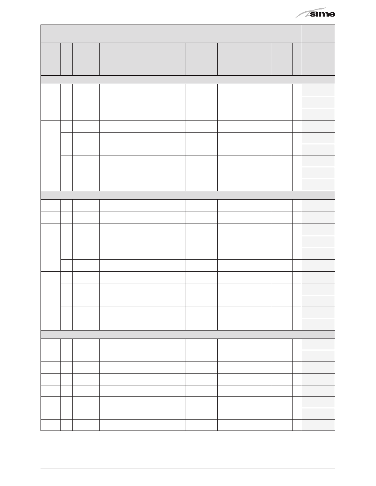
33
Use a pencil to note down the value of each modified parameter in the "Set Value" column in relation to the default value.
✎
➡
SCREEN
LEVEL
PARAMETER
DESCRIPTION DEFAULT RANGE
UNIT OF
MEASURE-
MENT
DATA TYPE
SET VALUE
6 - Domestic Hot Water
S600
U 6000
Comfort Setpoint Temperature for
Domestic Hot Water
45.0 10.0 ÷ 60.0 °C A
S602
U 6010
Reduced Setpoint Temperature for
Domestic Hot Water
42.0 10.0 ÷ 60.0 °C A
S606
I 6060
Maintaining Storage Tank When In
Reduced Mode
DISABLED
• DISABLED
• ENABLED
- D
S611
I 6120 DHW Anti-Legionella Function Enabled OFF
• OFF
• ON
- D
I 6122 Anti-Legionella Function Start Day 1 – Mon 1 - Mon ÷ 7 – Sun - I
I 6123 Anti-Legionella Function Start Time 00 00 ÷ 23 hh I
I 6125 Anti-Legionella Function Stop Time 03 00 ÷ 23 hh I
I 6127
Anti-Legionella DHW Temperature
Setpoint
54.0 10.0 ÷ 55.0 °C A
S615
I 6150 DHW Storage Tank Dynamic Setpoint ENABLED
• DISABLED
• ENABLED
- D
7- Energy Settings
S700
I 7000
Electrical-Primary Energy conversion
factor
40 0 ÷ 100 % I
S703
I 7030 Convenience type COST
• ENERGY
• COST
-
S705
I 7050 Boiler Gas Type METHANE
• METHANE
• GPL
- D
I 7054 Cost of Methane Gas 85 0 ÷ 999
€cent /
mc
I
I 7055 Cost of GPL Gas 140 0 ÷ 999 €cent / lt I
I 7058 Cost of Electricity 25 0 ÷ 999
€cent /
kWh
I
S710
I 7100 Photovoltaic System Included
NOT
INCLUDED
• NOT INCLUDED
• INCLUDED
- D
I 7104 Photovoltaic System Peak Power 3.0 0.0 - 99.9 kWp A
I 7106 Fixed Residential Building Consumption 1.0 0.0 - 99.9 kW A
I 7109 Heat Pump Nominal Heat Output 9 1 - 32 kW
S722
I 7220
Minimum External Temperature for Heat
Pump Convenience
-15.0 -50.0 ÷ 50.0 °C A
8- Communication
S800
I 8000 ModBus Boiler Address 2 0 ÷ 31 - I
I 8002 Heat Pump ModBus Address 1 0 ÷ 31 - I
S806
I 8060 Enabling modbus communication YES
• Yes
• No
- D
S812
I - Boiler information display - - -
S813
I - Boiler information display - - -
S814
I - Boiler information display - - -
S818
I - Heat Pump Information Display - - -
S819
I - Heat Pump Information Display - - -

34
3.5 Parameter functions
The configuration of the individual parameters described below allows operation of the Open Hybrid Mem ErP to adapt the
needs of the system created.
To access the parameters menu, refer to the section
“3.3 Pa-
rameter setting and display”.
3.5.1 General settings
PARAMETERS MENU
GENERAL SETTINGS
GENERATION
I/O CONFIGURATION
HEATING
COOLING
DOMESTIC HOT WATER
ENERGY SETTINGS
Press to access the general settings.
Climate control operating mode
GENERAL S100
CLIMATE CONTROL
OPERATING MODE:
HEAT
PAR. DESCRIPTION RANGE
1000
Climate control operating mode
· Off
· Heat
· Cool
This allows the user to select the operating mode of the climate control system (heating or cooling)
OFF: System switched off (heating and cooling disabled - for
example, mid-seasons).
HEAT: System in heating mode (cooling disabled - for exam-
ple, in winter).
COOL: System in cooling mode (heating disabled - for ex-
ample, in summer).
NB.
In the case of an external winter-summer selector, the setting
HEAT - COOL is no longer possible from this parameter.
There is the option of setting OFFmode.
Domestic hot water operating mode
GENERAL S102
DOMESTIC HOT
WATER OPERATING
MODE:
COMFORT
PAR. DESCRIPTION RANGE
1010
Domestic hot water operating mode
· Off
· Time
· Comfort
· Reduced
This allows the domestic hot water operating mode to be selected:
OFF: Domestic Hot Water Off.
TIME: Domestic hot water second level of the time program
(see instruction for use).
COMFORT: Domestic hot water always at comfort setpoint
level.
REDUCED: Domestic hot water always at reduced setpoint
level.
Select language
GENERAL S110
LANGUAGE SELECTION:
ITALIANO
PAR. DESCRIPTION RANGE
1100
Select language · Italiano
Setting time and day
GENERAL S112
TIME AND DATE
SETTING:
hh:mm
dd/mm/yyyy
16:45
10/11/2014
PAR. DESCRIPTION RANGE
Setting current hour · 00 - 23
Setting current minutes · 00 - 59
Setting current day · 01 - 31
Setting current month · 01 - 12
Setting current year · 2010 - 2199
Switch to daylight saving time
GENERAL S114
AUTOM. DAYLIGHT SAVING:
ENABLED
Trans. time:
Start : LAST
in MARCH
End: LAST
in OCTOBER
060min
SUNDAY
at 02.00
SUNDAY
at 03.00
PAR. DESCRIPTION RANGE
Enabling automatic switching to
daylight saving time-standard time
· Disabled
· Enabled
Transition time [min] · 00 - 240
Daylight saving time start week · First - Last
Daylight saving time start day · Monday - Sunday
Daylight saving time start month · January - December
Daylight saving time start time · 00 - 23
Daylight saving time end week · First - Last
Daylight saving time end day · Monday - Sunday
Daylight saving time end month · January - December
Daylight saving time end time · 00 - 23
Press to go back to the main menu.

35
3.5.2 Generation System Settings
PARAMETERS MENU
GENERAL SETTINGS
GENERATION
I/O CONFIGURATION
HEATING
COOLING
DOMESTIC HOT WATER
ENERGY SETTINGS
Press to access generation.
Anti-blocking function for devices
GENERATION S202
ANTI-LOCKING
DEVICE
FUNCTION
ACTIVE
PAR. DESCRIPTION RANGE
2020
Anti-blocking function for devices
· Active
· Not active
This allows the blocking of active electrical components to b
prevented (pumps, valves, boiler, heat pump, etc.) caused by
long periods of inactivity. Activates every day at 4.00
Automatic air venting function
GENERATION S203
AUTOMATIC
AIR VENTING FUNCTION:
NOT ACTIVE
PAR. DESCRIPTION RANGE
2030
Automatic air venting function
· Active
· Not active
If activated, this includes an automatic operating cycle for
bleeding purposes. See the section of the manual which refers to degassing during commissioning.
Automatic system filling function
GENERATION S207
AUTOMATIC
FILLING FUNCTION:
SYSTEM
ACTIVE
FILLING TIME: 180 s
PAR. DESCRIPTION RANGE
2070
Automatic system filling function
· Not active
· Active
2072
Filling time [s] · 1 - 999
If the pressure falls to below the minimum value (0.5 bar), the
system low pressure alarm intervenes and the system can be
filled by pressing the button
.
The filling procedure includes automatic opening cycles of the
filling valve until nominal pressure is reached.
System filling can be interrupted at any moment by pressing
the button
.
Boiler type
GENERATION S220
BOILER TYPE:
1
BRAVA HE ERP
PAR. DESCRIPTION RANGE
2200
Boiler type
· Not included
· BRAVA HE ErP
Heat Pump type
GENERATION S240
HEAT PUMP
TYPE:
1 - SHP M ERP
PAR. DESCRIPTION RANGE
2400
Heat Pump type
· Not included
· SHP M ErP
Priority Heat Pump Heating-DHW
GENERATION S248
HEAT PUMP
HEATING-DHW PRIORITY:
DOMESTIC HOT WATER
Maximum Time: 030min
PAR. DESCRIPTION RANGE
2480
Priority Heat Pump Heating-DHW
· Heating
· DHW
2482
Maximum time for Heat Pump DHW
priority over heating
· 0 - 500
If the heat pump receives requests for heating and domestic
hot water at the same time, it is possible to set which of the 2
functions will be served (if it is DHW, it is also possible to set
a maximum time after which the heat pump will go back to
heating).

36
Priority Heat Pump Cooling-DHW
GENERATION S249
HEAT PUMP
COOLING-DHW PRIORITY:
COOLING
Maximum Time: __ min
PAR. DESCRIPTION RANGE
2485
Priority Heat Pump Cooling-DHW
· Cooling
· DHW
2487
Maximum time for Heat Pump DHW
priority over cooling
· 0 - 500
If the heat pump receives requests for cooling and domestic
hot water at the same time, it is possible to set which of the 2
functions will be served (if it is DHW, it is also possible to set
a maximum time after which the heat pump will go back to
cooling).
Solar thermal system type
GENERATION S250
SOLAR THERMAL
SYSTEM TYPE:
1- SINGLE FIELD
COLLECTOR
PAR. DESCRIPTION RANGE
2500
Solar thermal system type
· Not included
· 1-SING.COLL.
If there is a solar thermal system, set:
– Single collector field: only one solar collector battery.
∆T Solar pumps
GENERATION S252
SOLAR PUMPS
Delta-T ON: 8.0ºc
Delta-T OFF: 4.0ºc
PAR. DESCRIPTION RANGE
2520
T ON solar pumps [°C] · 0.0 - 99.0
2522
T OFF solar pumps [°C] · 0.0 - 99.0
T ON: the difference in temperature between the solar collector sensor and the DHW storage tank low sensor for the
activation of the solar thermal system pump.
T OFF: the difference in temperature between the solar collector sensor and the DHW storage tank low sensor for the
deactivation of the solar thermal system pump.
Solar pump minimum operating time
GENERATION S253
SOLAR PUMP
MINIMUM
OPERATING TIME:
20s
PAR. DESCRIPTION RANGE
2530
Solar pump minimum operating time
[s]
· 0 - 600
When T ON is reached for the activation of the solar pump,
it remains active at least for the time set even if T OFF is
reached.
Solar collector anti-freeze function
GENERATION S254
SOLAR COLLECTOR
ANTI-FREEZE FUNCTION:
ACTIVE
MINIMUM TEMPERATURE:
-15.0ºc
PAR. DESCRIPTION RANGE
2540
Enabling solar collector anti-freeze
function
· Active
· Not active
2541
Solar collector minimum temperature
(Anti-freeze activation temperature) [°C]
· -40.0 - 10.0
The anti-freeze protection of the solar collectors must be made
using the anti-freeze fluid specified by the manufacturer.
The anti-freeze function allows the solar pumps to start when
the temperature detected approaches the temperatures guaranteed by the anti-freeze fluid. Therefore, set a minimum
temperature slightly higher than temperature guaranteed by
the anti-freeze fluid.
Solar collector cooling function
GENERATION S256
SOLAR COLLECTOR
COOLING FUNCTION:
ACTIVE
MAXIMUM TEMPERATURE:
120.0ºc
PAR. DESCRIPTION RANGE
2560
Enabling cooling function of solar collectors 1 and 2
· Active
· Not active
2561
Maximum temperature of solar collector sensor
(Anti-freeze activation temperature) [°C]
· 80.0 - 350.0
The solar collectors cooling function allows the solar pump
to start when the temperature detected approaches those of
the fluid evaporation. Therefore, set a maximum temperature
slightly lower than the evaporation temperature.

37
3.5.3 Input and Output Configuration
PARAMETERS MENU
GENERAL SETTINGS
GENERATION
I/O CONFIGURATION
HEATING
COOLING
DOMESTIC HOT WATER
ENERGY SETTINGS
Press to access i/o configuration.
m
WARNING
The following parameters allow the input and output values to be displayed and allow the associated
functions of some of these functions to be configured
Display of analogue input values
I/O CONFIG. S300
ANALOGUE INPUT
VALUE DISPLAY
B1:
51.8ºc B5: 60.2ºc
B2: 50.0ºc B6:
B3: 37.7ºc B7:
B4: 27.9ºc B8:
Digital input status display
I/O CONFIG. S301
DIGITAL INPUT
STATUS DISPLAY
ID1 : ON.
ID2 : OFF
B7 : ON
B8 : ON
Analogue output value display
I/O CONFIG. S302
ANALOGUE OUTPUT
VALUE DISPLAY
Y1 : 0.0
Y2 : 0.0
Digital output status display
I/O CONFIG. S303
DIGITAL OUTPUT
STATUS DISPLAY
NO1:
OFF NO5: OFF
NO2: OFF NO6: OFF
NO3: OFF NO7: OFF
NO4: OFF
External Sensor Connection
I/O CONFIG. S310
EXTERNAL SENSOR
CONNECTION:
FROM BOILER
PAR. DESCRIPTION RANGE
3100
External Sensor Connection
· Not included
· From boiler
· From HEAT PUMP
The external sensor is important for system operation and
thermo-regulation and should be installed in a suitable position. In the case of a "Heat Pump", the functions associated
with the external sensor lose accuracy and effectiveness.
B6 Digital input function
I/O CONFIG. S350
B6 DIGITAL INPUT
FUNCTION:
COOL MODE
PAR. DESCRIPTION RANGE
3500
B6 Digital input function
· None
· Cool mode
· Electrical convenience
The function assigned to the digital input (dry contact B6) can be:
– COOL MODE to switch system operation to cooling mode by
means of an external contact rather than by acting on the
display.
– ELECTRICAL CONVENIENCE to force electrical energy con-
venience by means of an external contact coming from, for
example, a photovoltaic inverter or a load management
control unit.
NO6 Digital output function
I/O CONFIG. S370
NO6
DIGITAL OUTPUT FUNC.:
COOL MODE
PAR. DESCRIPTION RANGE
3700
NO6 Digital output function
· None
· Cool mode
· Alarm signalling
The function assigned to the digital output (230Vac) can be:
– COOL MODE to activate any cooling zone valves present in
the system:
– ALARM SIGNALLING to indicate the presence of a general
alarm.

38
3.5.4 Heating
PARAMETERS MENU
GENERAL SETTINGS
GENERATION
I/O CONFIGURATION
HEATING
COOLING
DOMESTIC HOT WATER
ENERGY SETTINGS
Press to access heating.
Low Temperature Circuit Adjustment Type
HEATING S400
REGULATION TYPE
LOW TEMPERATURE
CIRCUIT:
CLIMATIC CURVE
PAR. DESCRIPTION RANGE
4001
Low Temperature Circuit Adjustment Type
· Fixed setpoint
· Climatic curve
The adjustment for the low temperature circuit can be
set in CLIMATIC CURVE or FIXED POINT.
Low Temperature Circuit Fixed setpoint
HEATING S402
LOW TEMPERATURE
CIRCUIT FIXED
SETPOINT:
40.0ºc
PAR. DESCRIPTION RANGE
4020
Low Temperature Circuit Fixed setpoint · 20.0 - 80.0
Setting the setpoint with S400 = FIXED POINT
Setpoint for Low Temperature Circuit Nominal Ambient
Temperature
HEATING S404
LOW TEMP. CIRCUIT
Nom Ambient Set
: 20.0ºc
Climatic Curve
: 1.0
Offset : 0.0ºc
Rotation at 20ºc : 0.0ºc
PAR. DESCRIPTION RANGE
4040
Setpoint for Low Temperature Circuit
Nominal Ambient Temperature
· 5.0 - 30.0
4023
Low Temperature Circuit Heating Curve · 0.2 - 2.2
4044
Low Temperature Circuit Heating Curve
Transfer
· -15.0 - 15.0
4045
Low Temperature Circuit Heating Curve
Rotation
· -15.0 - 15.0
The Low Temperature Circuit Ambient Heating setpoint is calculated using the climatic curve with S400 = CLIMATIC CURVE.
For the selection and adjustment (transfer, rotation) of the climatic curve, refer to the following indications.
It is possible to calculate the delivery setpoint (in winter adjustment) using up to no more than 22 climatic compensation
curves.
These curves associate the external temperature (X axis) with
the heating delivery setpoint (y axis): once the curve has been
selected on the basis of the building characteristics and the
ambient heating system, the delivery setpoint is calculated as
the intersection with the external temperature.
Climatic curve
Delivery setpoint with 20°C ambient (winter adjustment)
10
20 10 0 -10 -20 -3015 5 -5 -15 -25
20
30
40
50
60
70
80
90
100
Delivery setpoint °C
External Temperature °C
2.2
2
1.8
1.6
1.4
1.2
1
0.8
0.6
0.4
0.2
Fig. 35

39
Curve rotation and transfer for mild temperatures
It is possible to shift the set curve by adding or subtracting the
value set at parameter 4044 and rotating the curve around an
ideal axis at the point 20°C below the external temperature
using parameter 4045.
This way it is possible to modify undesired behaviour in the
mildest external temperature zone.
Offset (transfer) curve
0
20 10 0 -10 -20 -3015 5 -5 -15 -25
10
20
30
40
50
60
70
80
Delivery setpoint °C
External Temperature °C
1
+10°C
-10°C
Fig. 36
Curve rotation
0
20 10 0 -10 -20 -3015 5 -5 -15 -25
10
20
30
40
50
60
70
Delivery setpoint °C
External Temperature °C
1
+10°C
-10°C
Fig. 37
Setpoint Limits for Low Temperature Circuit Heating System
HEATING S406
LOW TEMPERATURE
CIRCUIT SETPOINT LIMIT
Minimum: 20.0ºc
Maximum: 45.0ºc
SAFETY THERMOSTAT 50ºc:
ENABLED
PAR. DESCRIPTION RANGE
4060
Minimum Setpoint for Low Temperature
Circuit Heating System
· 10.0 - 80.0
4062
Maximum Setpoint for Low Temperature
Circuit Heating System
· 10.0 - 80.0
4066
50°C Low Temperature Circuit Safety
Thermostat
· Disabled
· Enabled
Low temperature circuit: Setting the setpoint min-max limits
and enabling-disabling the 50°C safety thermostat.
NB.
With safety thermostat ENABLED it is not possible to set the
maximum setpoint to a temperature exceeding 45°C.
In order to set temperatures than this, the safety thermostat
must first be disabled.
Building cladding Inertia-Delay
HEATING S409
LOW TEMP. CIRCUIT
BUILDING STRUCTURE
DELAY - INERTIA:
4 hours
PAR. DESCRIPTION RANGE
4090
Building cladding Inertia-Delay
· 0
· 4
· 8
· 12
· 24
With radiating heating circuits with delivery temperature control with climatic curve based on the external temperature,
here it is possible to set the inertia/delay determined by the
building cladding.
High Temperature Heating Circuit Included
HEATING S414
HIGH TEMPERATURE
HEATING CIRCUIT
PRESENCE
YES
PAR. DESCRIPTION RANGE
4140
High Temperature Heating Circuit
Included
· No
· Yes
Set YES if installing High Temperature Kit.

40
High Temperature Circuit Fixed Setpoint
HEATING S415
HIGH TEMPERATURE
CIRCUIT FIXED
SETPOINT:
60.0ºc
PAR. DESCRIPTION RANGE
4150
High Temperature Circuit Fixed Setpoint · 20.0 - 80.0
High temperature heating circuit fixed setpoint (optional kit)
High Temperature Circuit Fixed Setpoint
HEATING S417
HIGH TEMPERATURE
CIRCUIT
PRIORITY:
OFF
PAR. DESCRIPTION RANGE
4170
High Temperature Circuit Priority
· Off
· On
The boiler is able to simultaneously serve the low and high
temperature circuits with a maximum high temperature power limit of 10kW. If higher demands are made, it is possible to
set the high temperature circuit priority so that if the boiler receives a simultaneous request for high and low temperature,
it will only serve the high temperature circuit.
Heating aid
HEATING S426
HEATING
COOPERATION
Enabling
: ON
Delay time : 030min
PAR. DESCRIPTION RANGE
4260
ENABLING HEATING AID
· On
· Off
4262
Delay Heating Aid · 0 - 999
If the function is enabled and the convenient source is not able
to meet the system request fully, then the less convenient
source can be activated as a form of a assistance after the set
delay time.
3.5.5 Cooling
PARAMETERS MENU
GENERAL SETTINGS
GENERATION
I/O CONFIGURATION
HEATING
COOLING
DOMESTIC HOT WATER
ENERGY SETTINGS
Press to access cooling.
Cooling System Fixed Setpoint
COOLING S500
COOLING SYSTEM
FIXED
SETPOINT:
15.0ºc
PAR. DESCRIPTION RANGE
5000
Cooling System Fixed Setpoint · 7.0 - 30.0
The cooling system temperature setpoint can be set manually
(it is the same value which can be modified in the user menu).
Cooling System Minimum Setpoint Limit
COOLING S503
COOLING SYSTEM
MINIMUM SETPOINT
LIMIT:
7.0ºc
PAR. DESCRIPTION RANGE
5030
Cooling System Minimum Setpoint Limit · 6.0 - 30.0
Minimum temperature limit for the cooling system setpoint.
Cooling System Setpoint with Humidistat Request
COOLING S506
COOLING SYSTEM
SETPOINT WITH
HUMIDISTAT REQUEST:
7.0ºc
PAR. DESCRIPTION RANGE
5060
Cooling System Setpoint with Humidistat
Request
· 0.0 - 50.0
Cooling system setpoint (in place of the nominal setpoint) if
a request is made by a humidistat. For example, a setpoint
lower than the nominal setpoint can be set if the water is sent
to a terminal for dehumidifying (for example, fan-coil closing
the radiating heads).

41
3.5.6 DHW
PARAMETERS MENU
GENERAL SETTINGS
GENERATION
I/O CONFIGURATION
HEATING
COOLING
DOMESTIC HOT WATER
ENERGY SETTINGS
Press to access domestic hot water.
Comfort Setpoint Temperature for DHW
DOMESTIC HOT WATER S600
COMFORT
SETPOINT TEMPERATURE
FOR DHW:
55.0ºc
PAR. DESCRIPTION RANGE
6000
COMFORT Setpoint Temperature for DHW
[°C]
· 10.0 - 80.0
The DHW COMFORT temperature can be set manually (it is the
same value which can be modified in the user menu).
Reduced Setpoint Temperature for DHW
DOMESTIC HOT WATER S602
REDUCED
SETPOINT TEMPERATURE
FOR DHW:
45.0ºc
PAR. DESCRIPTION RANGE
6010
REDUCED Setpoint Temperature for DHW
[°C]
· 10.0 - 80.0
The DHW REDUCED temperature can be set manually (it is
the same value which can be modified in the user menu).
Maintaining Storage Tank When In Reduced Mode
DOMESTIC HOT WATER S606
MAINTAINING STORAGE
TANK IN REDUCED MODE:
DISABLED
PAR. DESCRIPTION RANGE
6060
Maintaining Storage Tank When In Reduced Mode
· Disabled
· Enabled
When in DHW REDUCED mode, it is possible to enable/disable
the heat pump from maintaining the storage tank at the calculated setpoint temperature.
DHW Anti-legionella Function
DOMESTIC HOT WATER S611
ANTI-LEGIONELLA
FUNCTION
Activation
: NOT ACTIVE
Day : MONDAY
Start Time : 00:00
End Time : 03:00
Setpoint : 55.0ºc
PAR. DESCRIPTION RANGE
6120
DHW Anti-Legionella Function
Enabled
· OFF
· ON
6122
Anti-Legionella Function Start Day · 1 - Mon ÷ 7 – Sun
6123
Anti-Legionella Function Start Time · 00 - 23
6125
Anti-Legionella Function Stop Time · 00 - 23
6127
Anti-Legionella DHW Temperature
Setpoint
· 10.0 - 80.0
Settings relating to the anti-legionella function: Activation,
Day of the week, Start time, End time, Setpoint.
This function requires the Heat Pump to prepare the storage
tank on the basis of the parameters set here but only if in the
previous 7 days, the temperature has not reached the anti-legionella setpoint value.
DHW Storage Tank Dynamic Setpoint
DOMESTIC HOT WATER S615
DHW STORAGE TANK
DYNAMIC SETPOINT:
ENABLED
PAR. DESCRIPTION RANGE
6150
DHW Storage Tank Dynamic Setpoint
· Disabled
· Enabled
If the DHW STORAGE TANK DYNAMIC SETPOINT , is activated,
it allows the DHW storage tank to be maintained by the Heat
Pump up to the heat pump convenience temperature (not exceeding the DHW setpoint) rather than the fixed nominal setpoint.

42
3.5.7 Energy Settings
PARAMETERS MENU
GENERAL SETTINGS
GENERATION
I/O CONFIGURATION
HEATING
COOLING
DOMESTIC HOT WATER
ENERGY SETTINGS
Press to access the energy settings.
Electrical-primary energy conversion factor
ENERGY SETTINGS S700
ELECTRICAL-PRIMARY
ENERGY
CONVERSION FACTOR:
36%
PAR. DESCRIPTION RANGE
7000
Electrical-primary energy conversion
factor [%]
· 0 - 100
This is the transfer/generation output value (at point of delivery) of the electrical energy starting from the main energy
source (TOE, Tonne of Oil Equivalent).
Convenience type
ENERGY SETTINGS S703
CONVENIENCE TYPE:
COST
PAR. DESCRIPTION RANGE
7030
Convenience type
· Energy
· Cost
Convenience type selection: Energy or Cost
Energy costs
ENERGY SETTINGS S705
BOILER COSTS
Gas Type : METHANE
Pci Gas : 9460Wh/mc
Gas Cost : 85Ecent/kWh
HEAT PUMP COSTS
El. Cost : 25Ecent/kWh
PAR. DESCRIPTION RANGE
7050
Boiler Gas Type
· Methane
· Gpl
7054
Cost of Methane Gas · 0 - 999
7055
Cost of GPL Gas · 0 - 999
7058
Cost of Electricity · 0 - 999
Setting boiler costs: Gas type, Lower heat output (only with
manufacturer's password), Gas Cost
Setting heat pump costs: Cost of electricity.
Photovoltaic function
ENERGY SETTINGS S710
PHOTOVOLTAIC SYSTEM
NOT INCLUDED
Power peak : 03.0kWp
Fixed consumpt : 01.0kWp
HP Heat Output
: 09kW
PAR. DESCRIPTION RANGE
7100
Photovoltaic System Included
· Not included
· Included
7104
Photovoltaic System Peak Power · 0.0 - 99.9
7106
Fixed Residential Building Consumption
· 0.0 - 99.9
7109
Heat Pump Nominal Heat Output · 1 - 32
Photovoltaic function only available if there is a solar thermal
energy kit.
By setting PHOTOVOLTAIC SYSTEM INCLUDED and entering
the peak power, fixed consumption values of the building (taking into account at least one electrical appliance in operation)
and the nominal heat output of the heat pump, this function
estimates the electrical power produced by the photovoltaic
system (using the solar kit sensors). It then reduces the cost
of electricity in relation to the share of energy available from
the photovoltaic system, therefore raising the share of consumption of electricity produced by the photovoltaic system.
Minimum external temperature for Heat Pump convenience
ENERGY SETTINGS S722
MINIMUM EXTERNAL
TEMPERATURE FOR HEAT
PUMP CONVENIENCE:
-15.0ºc
PAR. DESCRIPTION RANGE
7220
Minimum external temperature for Heat
Pump convenience [°C]
· -50.0 - 50.0
Minimum external temperature below which the Heat Pump is
always considered not convenient.

43
3.5.8 Communication
PARAMETERS MENU
GENERATION
I/O CONFIGURATION
HEATING
COOLING
DOMESTIC HOT WATER
ENERGY SETTINGS
COMMUNICATION
Press to access Communication.
Modbus address
COMMUNICATION S800
MODBUS SETTINGS
Boiler ModBus Addr: 02
HP ModBus Address : 01
PAR. DESCRIPTION RANGE
8000
ModBus Boiler Address · 0 - 31
8002
Heat Pump modbus address · 0 - 31
Enter the boiler Modbus addresses here (standard value 2)
and the Heat Pump (standard value 1).
If carrying out rapid system configuration, the values are assigned automatically.
a
CAUTION:
Do not use the same address values for both.
Enabling modbus communication
COMMUNICATION S806
ENABLING
MODBUS
COMMUNICATION?
YES
PAR. DESCRIPTION RANGE
8060
Enabling modbus communication
· Yes
· No
Enable or disable Modbus communication
Boiler information display
COMMUNICATION S812
BOILER INFORMATION
Heating Enabling : OFF
Heat. Operation : OFF
DHW Enabling : ON
DHW Operation : ON
Burner : 48%
Alarm : OFF
Boiler information display
COMMUNICATION S813
BOILER INFORMATION
Heat Setpoint : 43.4ºc
Heat. Deliv. T. : 45.9ºc
DHW Setpoint : 45.0ºc
DHW Deliv. T : 27.0ºc
DHW Flow Rate : 4.6l/m
Pressure : 1.6bar
Boiler information display
COMMUNICATION S814
BOILER INFORMATION
External T. : -1.3ºc
Heat Pump Information Display
COMMUNICATION S818
HEAT PUMP INFORMATION
Request : HEAT.
Heat. Setpoint
: 55.0ºc
Cool. Setpoint
: 7.0ºc
Ext. Temperat. : 3.6ºc
Defrosting : OFF
Heat Pump Information Display
COMMUNICATION S819
HEAT PUMP INFORMATION
T.Return : 25.0ºc
T.Delivery : 26.0ºc
Comp. Int. T. : 1.6ºc
Comp. Dis.T. : 43.0ºc
Low Pressure : 7.1bar
High Pressure : 28.4bar

44
4 MAINTENANCE
4.1 Adjustments
For the OPEN HYBRID MEM ErP to operate efficiently and correctly, it is recommended that the User engages a Professionally
Qualified Technician to carry out
ANNUAL
maintenance operations on the system.
For this maintenance, refer to the information provided in the manual supplied with the appliances.
It is also recommended that the state of the storage tank magnesium anode is checked
EVERY TWO YEARS
and replaced if neces-
sary.
m
WARNING
Maintenance interventions must ONLY be carried out by professionally qualified personnel.
4.2 Alarms
If at least one alarm is present, the button will flash.
In this section of the installer menu, all the alarms currently present are listed followed by the alarm log memory.
Consultation of the list in a cyclical manner is possible by using the buttons
and .
Consultationof the individual alarms is also available from the user menu by pressing the button
.
Alarm
Code
Description Possible causes Solutions
A001
A002
A003
A004
A005
Sensor B1 Fault Alarm
Sensor B2 Fault Alarm
Sensor B3 Fault Alarm
Sensor B4 Fault Alarm
Sensor B5 Fault Alarm
Sensitive element of sensor faulty Replace the sensor
Incorrect or no connection between the
sensor and the MEM control unit
Restore the connection according to the wiring
diagram
Fault in the analogue input of the MEM
control unit
Check the input be attempting to connect another
sensor; replace the MEM control unit if necessary
A018
Solar thermal circuit operation
alarm (Delta-T too high)
Fault or block in the solar thermal circulator Release or replace the circulator
Incorrect or no connection between the
solar circulator and the MEM control unit
Restore the connection according to the wiring
diagram
Fault in the MEM control unit output
Check that there is a 230Vac output voltage at
the control unit; replace the MEM control unit if
necessary
Incorrect position of the B2 storage tank
low sensor
Restore the correct position of the B2 sensor
Incorrect reading of the B2 storage tank
low sensor or the B4 solar thermal collector
sensor
Check that the values measured are in line and
replace the uncalibrated sensor if necessary
Solar thermal circuit draining
Check the solar thermal circuit pressure and restore
the missing fluid with the correct concentration of
ant-freeze. Check the relief valves or fittings for leaks.
Check the solar thermal expansion vessel prefilling
pressure
A020
Alarm for Storage tank temperature
too high
Overtemperature due to excessive thermal
energy supplied by solar thermal system
Check the operating dynamics of the solar thermal
energy system in critical conditions. Contact the
SIME manufacturer if necessary
Incorrect reading of the B1 storage tank
high sensor
Check that the values measured are in line and
replace the uncalibrated sensor if necessary
A021
Alarm for System Safety Thermostat
Intervention
Delivery temperature higher than the thermostat intervention temperature
Check and lower the maximum limit of the low
temperature circuit setpoint
Safety thermostat fault Check and replace the safety thermostat if necessary.
Incorrect or no connection between the
safety thermostat and the MEM control
unit
Restore the connection according to the wiring
diagram

45
Alarm
Code
Description Possible causes Solutions
A023 Alarm for Low System Pressure
Air bleeding from system
Fill the system from the remote control or using the
screw on the solenoid valve
Plumbing leaks
Check and repair any plumbing leaks; then fill the
system
Overpressure relive valve intervention in
boiler or heat pump
Check the heating expansion vessel and the relief
valve; then fill the system
Incorrect reading the boiler pressure
transducer
Check pressure transducer operation and replace if
necessary
A024 Alarm for High System Pressure
Boiler expansion vessel faulty or empty Check the expansion vessel; then fill the system
Leak from system filling valve
Check the position of the screw and any leakage in
the valve. Replace if necessary.
Incorrect reading the boiler pressure
transducer
Check pressure transducer operation and replace if
necessary
A050
A051
A052
General Alarm for ModBus Communication
Alarm for ModBus Communication
with Boiler
Alarm for ModBus Communication
with Heat Pump
Incorrect communication parameters and
addresses setting in the MEM control unit
or heat pump or the bus converter for the
boiler (dip-switch)
Check the address setting or communication parameters and correct if necessary.
The Bus converter dip-switches must be set to
1=OFF, 2=OFF, 3=OFF, 4=ON
No electrical connection or incorrect Bus
line to the boiler or heat pump
Check and restore the Bus line connection if necessary
Fault in the Bus communication converter
for the boiler
Check and replace the Bus converter for the boiler if
necessary
A100 General Alarm Boiler -
Refer to the boiler instruction manual with reference
to the alarm codes (if communicated)
A200 General Alarm Heat Pump -
Refer to the heat pump instruction manual with
reference to the alarm codes (if communicated)
m
If the remote control unit is switched off completely, then one of the following situation may have occurred:
Possible causes Solutions
No power to electrical panel Check and restore the electrical power supply of the board if necessary
Intervention of the transformer protection fuses Check and restore the fuses FU1 and FU2 if necessary
Fault in the TM1 transformer Check and replace the transformer if necessary
Fault in MEM control unit
Check that the MEM control unit leds activate if it is receiving electrical power. Replace
the MEM control unit if necessary
Incorrect or no connection between the remote control unit
and the MEM control unit
Restore the connection according to the wiring diagram
Incorrect remote control unit address
Check and if necessary restore value 32 in the remote control unit address (see instruction
sheet supplied)

46
4.3 Any pump faults and possible solutions
LED colour Pump status Fault Possible solution
Red-Green
flashing
"Transient safety shutdown"; Anomaly
in progress
After eliminating the anomaly, the pump
restarts automatically
Network voltage too high or too low;
(160V > Vn > 280V)
- Check network voltage
Motor overload; rotor friction or blockage
due to the presence of debris
- Check the characteristics of the system
water; clean the system of any debris
Excessive speed; the pump rotor is actuated by an external factor and is rotating at
a speed exceeding the maximum permitted speed
- Check that there is no external flow in
the system (no other pump in operation)
Overcurrent; stator winding is in short
circuit due to water
- Check for leaks in the system
The temperature inside the motor is too
high
- Check the water temperature in relation
to ambient temperature
The pump is obstructed by an external
flow (> 1200l/h) in the opposite direction
- Eliminate or reduce the external flow (<
1200l/h)
Flashing red "Permanent safety shutdown"
Pump blocked due to debris in the system
- Remove and reconnect the electrical
power supply (OFF - ON)
Fault in the electronic board and/or the
motor
- If the "red LED" continues to flash:
- REPLACE THE PUMP
LED off Stationary
No electrical power - Check the electrical power connection
LED faulty - Check if the pump can operate
Electronic board faulty - REPLACE THE PUMP
4.4 Alarm log
ALARM LOG A000
ALARM LOG
TO DISPLAY
PRESS
Press the button to access
Use the buttons
and to scroll through the alarm log
memory list
ALARM A001
B1 SENSOR FAULT
Contact the authorised
tech. assist. centre
(Display example)

47
5 APPLICATION DIAGRAMS
APPLICATION DIAGRAM 1a: radiating panel heating only
Water Mains
HEAT
PUMP
Gas
RADIATING PANEL
SYSTEM POWER SUPPLY
(heating only)
RADIATING PANEL
SYSTEM POWER SUPPLY
(heating only)
T
T
T
T
T
TA TA TA TA
TA TA TA TA
MULTIFUNCTION
Digital Input
(for example, Summer/Winter selector)
EXTERNAL SENSOR
(optional)
MEM REMOTE CONTROL
SOLAR SENSOR
(optional)
SOLAR
COLLECTOR
(optional)
Sensor PT1000
Cable 2x0.5mm²
Sensor NTC
Cable 2x0.5mm²
RJ12 telephone cable supplied as standard
L=6m extendable up to 25m
NO Contact
Cable 2x0.5mm²
LOW TEMPERATURE CIRCUIT request
NO Contact - Cable 2x0.5mm²
Communication bus
Shielded cable 3x0.25mm²
NOTE:
– Radiating panel heating only
– All the safety limit microswitches are connected in parallel to the LOW TEMPERATURE CIRCUIT REQUEST input (NO dry contact)
– The head request is always supplied by the TA (ambient thermostats).

48
APPLICATION DIAGRAM 2a: radiating panel heating only - Fan convectors cooling/dehumidifying only
Water Mains
Gas
T
T
T
T
Enabling COOLING fan convector
heads and disabling HEATING
radiating heads
T
TA TA TA TA
TA TA TA TA
Sensor PT1000
Cable 2x0.5mm²
Sensor NTC
Cable 2x0.5mm²
RJ12 telephone cable supplied as standard
L=6m extendable up to 25m
NO Contact
Cable 2x0.5mm²
COLD MODE output 230Vac 1A max - cable 2x1.5mm²
LOW TEMPERATURE CIRCUIT request
NO Contact - Cable 2x0.5mm²
Communication bus
Shielded cable 3x0.25mm²
RADIATING PANEL
SYSTEM POWER SUPPLY
(heating only)
RADIATING PANEL
SYSTEM POWER SUPPLY
(heating only)
FAN CONVECTORS
(only cooling
dehumidify)
FAN CONVECTORS
(only cooling
dehumidify)
MEM REMOTE CONTROL
HEAT
PUMP
SOLAR
COLLECTOR
(optional)
EXTERNAL SENSOR
(optional)
SOLAR SENSOR
(optional)
MULTIFUNCTION
Digital Input
(for example, Summer/Winter selector)
NOTE:
– Radiating panel heating only
– All the safety limit microswitches are connected in parallel to the LOW TEMPERATURE CIRCUIT REQUEST input (NO dry contact)
– Fan convectors cooling/dehumidifying only
– COOL MODE output (230Vac 1A max) must enable the fan convectors head and disable the radiating panel head
– The head request is always supplied by the TA (ambient thermostats).
– If the fan convectors are to also operate in heating in spring and autumn, eliminate the COOL MODE output connection and
appropriately control the fan convectors and radiating floor heads using the ambient thermostats

49
APPLICATION DIAGRAM 2b: radiating panel heating only - Fan convectors cooling/dehumidifying only
Water Mains
Gas
T
T
T
T
T
TA
TA TA TA TA
Sensor PT1000
Cable 2x0.5mm²
Sensor NTC
Cable 2x0.5mm²
RJ12 telephone cable supplied as standard
L=6m extendable up to 25m
NO Contact
Cable 2x0.5mm²
LOW TEMPERATURE CIRCUIT request
NO Contact - Cable 2x0.5mm²
Communication bus
Shielded cable 3x0.25mm²
RADIATING PANEL
SYSTEM POWER SUPPLY
(heating only)
FAN CONVECTORS
(only cooling
dehumidify)
FAN CONVECTORS
(only cooling
dehumidify)
FAN CONVECTORS
(only cooling
dehumidify)
AB
B
A
DIVERTER VALVE
COOLING-HEATING
(not supplied)
COLD MODE output
230Vac 1A max
cable 2x1.5mm²
MEM REMOTE CONTROL
HEAT
PUMP
SOLAR
COLLECTOR
(optional)
EXTERNAL SENSOR
(optional)
SOLAR SENSOR
(optional)
MULTIFUNCTION
Digital Input
(for example, Summer/Winter selector)
NOTE:
– Radiating panel heating only
– All the safety limit microswitches are connected in parallel to the LOW TEMPERATURE CIRCUIT REQUEST input (NO dry contact)
– Fan convectors cooling/dehumidifying only
– The COOL MODE (230Vac 1A max) output must switch the HEATING/COOLING DIVERTER VALVE
– The head request is always supplied by the TA (ambient thermostats).
– If the fan convectors are to also operate in heating in spring and autumn, remove the diverter valve and appropriately control the fan
convectors and radiating floor heads using the ambient thermostats.

50
APPLICATION DIAGRAM 3a: fan convectors heating + cooling/dehumidifying
Water Mains
Gas
T
T
T
TA
Sensor PT1000
Cable 2x0.5mm²
Sensor NTC
Cable 2x0.5mm²
RJ12 telephone cable supplied as standard
L=6m extendable up to 25m
NO Contact
Cable 2x0.5mm²
LOW TEMPERATURE CIRCUIT request
NO Contact - Cable 2x0.5mm²
Communication bus
Shielded cable 3x0.25mm²
FAN CONVECTORS
(heating +
cooling/dehumidify
FAN CONVECTORS
(heating +
cooling/dehumidify
FAN CONVECTORS
(heating +
cooling/dehumidify
FAN CONVECTORS
(heating +
cooling/dehumidify
FAN CONVECTORS
(heating +
cooling/dehumidify
FAN CONVECTORS
(heating +
cooling/dehumidify
T
T
TA
MEM REMOTE CONTROL
HEAT
PUMP
SOLAR
COLLECTOR
(optional)
EXTERNAL SENSOR
(optional)
SOLAR SENSOR
(optional)
MULTIFUNCTION
Digital Input
(for example, Summer/Winter selector)
NOTE:
– Fan convectors heating + cooling/dehumidifying
– All the safety limit microswitches are connected in parallel to the LOW TEMPERATURE CIRCUIT REQUEST input (NO dry contact)
– The setting PAR2480=HEATING is recommended

51
APPLICATION DIAGRAM 4a: radiating panel heating + cooling - independent dehumidifiers (only electrical)
Water Mains
Gas
T
T
T
T
T
TA TA TA TA
TA TA TA TA
Sensor PT1000
Cable 2x0.5mm²
Sensor NTC
Cable 2x0.5mm²
RJ12 telephone cable supplied as standard
L=6m extendable up to 25m
NO Contact
Cable 2x0.5mm²
LOW TEMPERATURE CIRCUIT request
NO Contact - Cable 2x0.5mm²
Communication bus
Shielded cable 3x0.25mm²
RADIATING PANEL
SYSTEM POWER SUPPLY
(heating + cooling)
RADIATING PANEL
SYSTEM POWER SUPPLY
(heating + cooling)
DEHUMIDIFIERS
(independent - electrical only)
DEHUMIDIFIERS
(independent - electrical only)
UR
UR
Request to INCREASE LOW TEMPERATURE CIRCUIT SETPOINT
NO Contact - Cable 2x0.5mm² (optional)
MEM REMOTE CONTROL
HEAT
PUMP
SOLAR
COLLECTOR
(optional)
EXTERNAL SENSOR
(optional)
SOLAR SENSOR
(optional)
MULTIFUNCTION
Digital Input
(for example, Summer/Winter selector)
NOTE:
– Radiating panel heating + cooling.
– All the safety limit microswitches are connected in parallel to the LOW TEMPERATURE CIRCUIT REQUEST input (NO dry contact)
– Independent dehumidifiers (only electrical)
– The UR (humidistats) activate the dehumidifiers, if included, and provide the request to INCREASE LOW TEMPERATURE CIRCUIT SET-
POINT (NO dry contact)
– The head request is always supplied by the TA (ambient thermostats).

52
APPLICATION DIAGRAM 4b: radiating panel heating + cooling - hydronic dehumidifiers (hydronic + electrical)
Water Mains
HEAT
PUMP
Gas
T
T
T
T
T
TA TA TA TA
TA TA TA TA
SOLAR
COLLECTOR
(optional)
Sensor PT1000
Cable 2x0.5mm²
Sensor NTC
Cable 2x0.5mm²
RJ12 telephone cable supplied as standard
L=6m extendable up to 25m
NO Contact
Cable 2x0.5mm²
LOW TEMPERATURE CIRCUIT request
NO Contact - Cable 2x0.5mm²
Communication bus
Shielded cable 3x0.25mm²
RADIATING PANEL
SYSTEM POWER SUPPLY
(heating + cooling)
RADIATING PANEL
SYSTEM POWER SUPPLY
(heating + cooling)
DEHUMIDIFIERS
(hydronic + electrical)
DEHUMIDIFIERS
(hydronic + electrical)
UR
UR
MEM REMOTE CONTROL
EXTERNAL SENSOR
(optional)
SOLAR SENSOR
(optional)
MULTIFUNCTION
Digital Input
(for example, Summer/Winter selector)
NOTE:
– Radiating panel heating + cooling.
– All the safety limit microswitches are connected in parallel to the LOW TEMPERATURE CIRCUIT REQUEST input (NO dry contact)
– Hydronic dehumidifiers (hydronic + electrical)
– The RH (humidistats) activate the dehumidifiers and the corresponding heads for the hydronic circuit.
– The request to the remaining head is always supplied by the TA (ambient thermostats).

53
APPLICATION DIAGRAM 4c: radiating panel heating + cooling - Fan convectors only cooling/dehumidifying
Water Mains
Gas
T
T
T
T
T
TA TA TA TA
TA TA TA TA
Sensor PT1000
Cable 2x0.5mm²
Sensor NTC
Cable 2x0.5mm²
RJ12 telephone cable supplied as standard
L=6m extendable up to 25m
NO Contact
Cable 2x0.5mm²
LOW TEMPERATURE CIRCUIT request
NO Contact - Cable 2x0.5mm²
Communication bus
Shielded cable 3x0.25mm²
RADIATING PANEL
SYSTEM POWER SUPPLY
(heating + cooling)
RADIATING PANEL
SYSTEM POWER SUPPLY
(heating + cooling)
FAN CONVECTORS
(only cooling
/dehumidify)
FAN CONVECTORS
(only cooling
/dehumidify)
UR
Request to LOWER LOW TEMPERATURE CIRCUIT SETPOINT
NO Contact - Cable 2x0.5mm² (optional)
MEM REMOTE CONTROL
HEAT
PUMP
SOLAR
COLLECTOR
(optional)
EXTERNAL SENSOR
(optional)
SOLAR SENSOR
(optional)
MULTIFUNCTION
Digital Input
(for example, Summer/Winter selector)
UR
Disabling
radiating panel
heads
Disabling
radiating panel
heads
NOTE:
– Radiating panel heating + cooling.
– All the safety limit microswitches are connected in parallel to the LOW TEMPERATURE CIRCUIT REQUEST input (NO dry contact)
– Fan convectors cooling/dehumidifying only
– The RH (humidistats) activate the fan convectors and the corresponding heads and disable all the other radiating panel heads.
– Furthermore, the UR provide the request to LOWER LOW TEMPERATURE CIRCUIT SETPOINT (NO dry contact).
– The request to the remaining head is always supplied by the TA (ambient thermostats).

54
APPLICATION DIAGRAM: high temperature circuit kit
TA
Request for HIGH TEMPERATAURE CIRCUIT NO contact - Cable 2x0.5mm²
TOWEL
RADIATOR
(high temperature)
and/or fan convectors
NOTE:
– High temperature circuit only heating applicable in all previous diagrams.
– The request is made by the TA (ambient thermostat) at the HIGH TEMPERATURE CIRCUIT REQUEST input (NO dry contact).

55
6 PRODUCT DATA SHEET
Open Hybrid MEM ErP
25-006
8114400
25-009
8114401
25-012
8114402
30-006
8114403
30-009
8114404
HEATING
C.H. seasonal energy efficiency of heat pump [“I”] (%) 152 151 152 152 151
Contribution of temperature control (%) 2 2 2 2 2
Contribution of additional boiler (%) -16 -8 -4 -19 -11
Contribution of solar energy (%) 0 0 0 0 0
Energy efficiency class of combined central heating
A++ A++ A+++ A++ A++
Seasonal energy efficiency of combined central heating (%) 138 145 150 135 142
Weighting factor of preferential heating equipment heat output
[“II”]
0,26 0,14 0,07 0,31 0,18
Value of mathematical expression 294/(11*Pnominal)[“III”] 4,63 2,95 2,16 4,63 2,95
Value of mathematical expression 115/(11*Pnominal)[“IV”] 1,81 1,15 0,84 1,81 1,15
DOMESTIC HOT WATER
D.H.W. seasonal energy efficiency in combi boiler (%) 82 82 82 80 80
D.H.W load profile declared XL XL XL XL XL
Contribution of solar energy (%) 0 0 0 0 0
Combined D.H.W. energy efficiency class
A A A A A
Combined D.H.W. energy efficiency in average climatic conditions
(%)
82 82 82 80 80
Value of mathematical expression (220*Qref)/Qnonsol[“II”] - - - - -
Value of mathematical expression (Qaux*2,5)/(220*Qref)[“III”] - - - - -
Conforming to Annex IV (item 6) of the Delegated Regulation (EU) No. 811/2013 which supplements Directive 2010/30/EU

56
Open Hybrid MEM ErP
30-012
8114405
35-006
8114406
35-009
8114407
35-012
8114408
HEATING
C.H. seasonal energy efficiency of heat pump [“I”] (%) 152 152 151 152
Contribution of temperature control (%) 2 2 2 2
Contribution of additional boiler (%) -7 -25 -15 -9
Contribution of solar energy (%) 0 0 0 0
Energy efficiency class of combined central heating
A++ A++ A++ A++
Seasonal energy efficiency of combined central heating (%) 147 129 138 145
Weighting factor of preferential heating equipment heat output
[“II”]
0,11 0,42 0,25 0,16
Value of mathematical expression 294/(11*Pnominal)[“III”] 2,16 4,63 2,95 2,16
Value of mathematical expression 115/(11*Pnominal)[“IV”] 0,84 1,81 1,15 0,84
DOMESTIC HOT WATER
D.H.W. seasonal energy efficiency in combi boiler (%) 80 80 80 80
D.H.W load profile declared XL XL XL XL
Contribution of solar energy (%) 0 0 0 0
Combined D.H.W. energy efficiency class
A A A A
Combined D.H.W. energy efficiency in average climatic conditions
(%)
80 80 80 80
Value of mathematical expression (220*Qref)/Qnonsol[“II”] - - - -
Value of mathematical expression (Qaux*2,5)/(220*Qref)[“III”] - - - -
Conforming to Annex IV (item 6) of the Delegated Regulation (EU) No. 811/2013 which supplements Directive 2010/30/EU

57
Open Hybrid MEM ErP
25-006 S
8114409
25-009 S
8114410
25-012 S
8114411
30-006 S
8114412
30-009 S
8114413
HEATING
C.H. seasonal energy efficiency of heat pump [“I”] (%) 152 151 152 152 151
Contribution of temperature control (%) 2 2 2 2 2
Contribution of additional boiler (%) -16 -8 -4 -19 -11
Contribution of solar energy (%) - - - - -
Energy efficiency class of combined central heating
A++ A++ A+++ A++ A++
Seasonal energy efficiency of combined central heating (%) 138 154 150 135 142
Weighting factor of preferential heating equipment heat output
[“II”]
0,26 0,14 0,07 0,31 0,18
Value of mathematical expression 294/(11*Pnominal)[“III”] 4,63 2,95 2,16 4,63 2,95
Value of mathematical expression 115/(11*Pnominal)[“IV”] 1,81 1,15 0,84 1,81 1,15
DOMESTIC HOT WATER
D.H.W. seasonal energy efficiency in combi boiler (%) 82 82 82 80 80
D.H.W load profile declared XL XL XL XL XL
Contribution of solar energy (%) 5 5 5 4 4
Combined D.H.W. energy efficiency class
A A A A A
Combined D.H.W. energy efficiency in average climatic conditions
(%)
87 87 87 84 84
Value of mathematical expression (220*Qref)/Qnonsol[“II”] 1,17 1,17 1,17 1,17 1,17
Value of mathematical expression (Qaux*2,5)/(220*Qref)[“III”] 7,37 7,37 7,37 7,37 7,37
Conforming to Annex IV (item 6) of the Delegated Regulation (EU) No. 811/2013 which supplements Directive 2010/30/EU
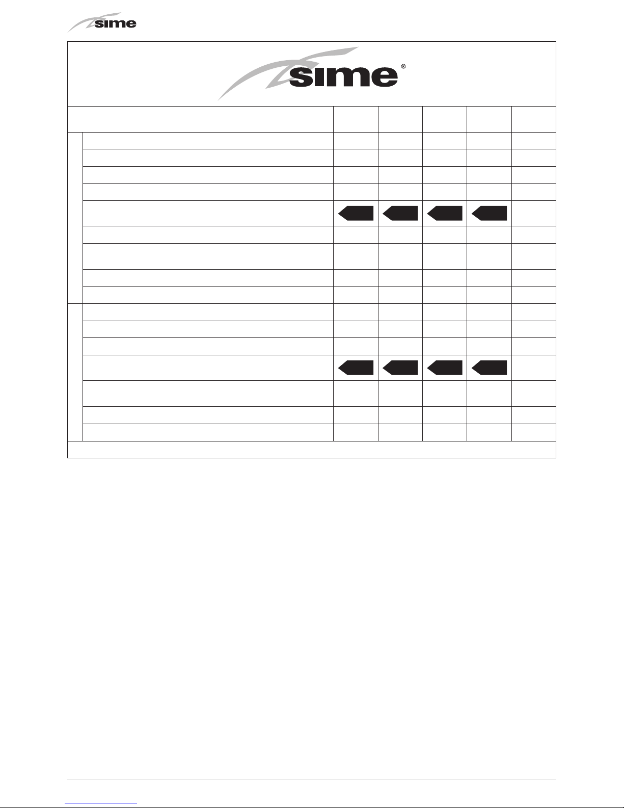
58
Open Hybrid MEM ErP
30-012 S
8114414
35-006 S
8114415
35-009 S
8114416
35-012 S
8114417
HEATING
C.H. seasonal energy efficiency of heat pump [“I”] (%) 151 152 151 152
Contribution of temperature control (%) 2 2 2 2
Contribution of additional boiler (%) -7 -25 -15 -10
Contribution of solar energy (%) - - - -
Energy efficiency class of combined central heating
A++ A++ A++ A++
Seasonal energy efficiency of combined central heating (%) 147 129 138 145
Weighting factor of preferential heating equipment heat output
[“II”]
0,11 0,42 0,25 0,16
Value of mathematical expression 294/(11*Pnominal)[“III”] 2,16 4,63 2,95 2,16
Value of mathematical expression 115/(11*Pnominal)[“IV”] 0,84 1,81 1,15 0,84
DOMESTIC HOT WATER
D.H.W. seasonal energy efficiency in combi boiler (%) 80 80 80 80
D.H.W load profile declared XL XL XL XL
Contribution of solar energy (%) 4 4 4 4
Combined D.H.W. energy efficiency class
A A A A
Combined D.H.W. energy efficiency in average climatic conditions
(%)
84 84 84 84
Value of mathematical expression (220*Qref)/Qnonsol[“II”] 1,17 1,17 1,17 1,17
Value of mathematical expression (Qaux*2,5)/(220*Qref)[“III”] 7,37 7,37 7,37 7,37
Conforming to Annex IV (item 6) of the Delegated Regulation (EU) No. 811/2013 which supplements Directive 2010/30/EU

59

Fonderie Sime S.p.A - Via Garbo, 27 - 37045 Legnago (Vr)
Tel. +39 0442 631111 - Fax +39 0442 631292 - www.sime.it
Fonderie SIME SpA reserves the right to make changes at any time without prior notice in order to improve its products
without compromising the essential characteristics.
 Loading...