


Format B
Installation and
servicing instructions
UK
Please read the Important Notice within
this guide regarding your boiler warranty
199838
ENSURE THAT THESE INSTRUCTIONS ARE LEFT
FOR THE USER AFTER COMPLETION OF THE
BENCHMARK SECTION

All descriptions and illustrations provided in this manual have been carefully prepared but we reserve the right to make changes
and improvements in our products that may affect the accuracy of the information contained in this manual.
IMPORTANT NOTICE
For the first year all of our appliances are protected by our manufacturer’s guarantee which covers both parts and
labour.
As you would expect from Sime Ltd, it is our aim to provide our valued customers with the best in after sales and
service.
To take advantage of any extended warranty offered, all you have to do is to adhere to these 3 simple conditions:
• The installation must be carried out to Manufacturers/Benchmark Standards by a Gas Safe Registered
Engineer, and recorded in the installation manual.
• The appliance must be registered with both Sime Ltd and Gas Safe within 30 days of installation.
• The appliance must be serviced annually, by either Sime Ltd or a Gas Safe registered engineer- ensuring that the
Benchmark service record in the installation manual is completed.
Failure to comply with the above will result in only the 12 month warranty being offered.
In the absence of any proof of purchase, the 12 month warranty period will commence from the date of manufacture
of the boiler as shown on the appliance data plate.


The Benchmark Scheme
Sime Ltd is a licensed member of the Benchmark Scheme which aims to improve the standards of installation and
commissioning of domestic heating and hot water systems in the UK and to encourage regular servicing to optimise safety, efficiency and performance.
Benchmark is managed and promoted by the Heating and Hotwater Industry Council.
For more information visit www
.centralheating.co.uk

Format 80 B:
Gas Council number 47-283-07
Format 100 B:
Gas Council number 47-283-08
These appliances comply with the S.E.D.B.U.K. scheme, band “D”
SIME COMBINATION BOILERS
Installer checklist
Please remember to carry out the following checks after installation. This will achieve complete customer satis-
faction, and avoid unnecessary service calls. A charge will be made for a service visit where the fault is not due to
a manufacturing defect.
– Has a correct by-pass been fitted and adjusted?
– Has the system been flushed in accordance with the guidelines given in BS7593 “Treatment of water in domes-
tic hot water central heating systems”?
– Is the system and boiler full of water, and the correct pressure showing on the pressure gauge?
– Is the Auto Air Vent open?
– Has the pump been rotated manually?
– Is the gas supply working pressure correct?
– Is the boiler wired correctly? (See installation manual).
– Has the D.H.W. flow rate been set to the customer requirements?
– Has the customer been fully advised on the correct use of the boiler, system and controls?
– Has the log book provided been completed?
IPX4D
Important Information
IT IS A STATUTORY REQUIREMENT THAT ALL GAS APPLIANCES ARE INSTALLED BY COMPETENT PERSONS, IN
ACCORDANCE WITH THE GAS SAFETY (INSTALLATION AND USE) REGULATIONS (CURRENT EDITION). The manufacturer’s instructions must not be taken as overriding any statutory requirements, and failure to comply with these
regulations may lead to prosecution.
No modifications to the appliance should be made unless they are fully approved by the manufacturer.
GAS LEAKS: DO NOT OPERATE ANY ELECTRICAL SWITCH, OR USE A NAKED FLAME. TURN OFF THE GAS SUPPLY
AND VENTILATE THE AREA BY OPENING DOORS AND WINDOWS CONTACT THE GAS EMERGENCY SERVICE ON
0800111999.
Please refer to commissioning instructions for filling in the checklist of this installation guide.
Note: All Gas Safe registered installers carry a ID Card.
You can check your installer is Gas Safe Registered by calling 0800 408 5577

6
1.1 INTRODUCTION
The Sime “FORMAT B” are wall mounted, fan assisted
balanced flue combination boilers.
The appliance is supplied suitable for use with natural gas,
L.P.G. and provide central heating and instantaneous
production of D.H.W. Heat output is varied according to
demand by the modulating gas control on both D.H.W. and C.H.
The appliance is supplied with a telescopic air/flue duct
suitable for wall thicknesses up to 635 mm (25 in) although
extension duct kits are available (see details in section 3.4).
The combined flue and air duct can exit the boiler from either
side or from the rear of the appliance. A vertical extension
and additional flue elbow may be fitted. If required, the boilers
can also be fitted with a separate flues kit (see section 3 for
details).
The boiler is designed for use with sealed primary water
systems and is supplied fully assembled and equipped with
complete valve packs.
The boiler can be used with a 24V room thermostat (class II
according to EN 60730.1).
This booklet provides instructions for the boiler models:
“FORMAT 80 B - FORMAT 100 B” with following features:
– electronic ignition,
– fully modulating.
1 TECHNICAL FEATURES AND DIMENSIONS
TABLE 2 - Minimum clearances
For ventilation For servicing
ABOVE THE APPLIANCE CASING 200 mm 300 mm
AT THE R.H.S. 15 m m 15 m m
AT THE L.H.S. 15 m m 15 m m
BELOW THE APPLIANCE CASING 200 mm 200 mm
IN FRONT OF THE APPLIANCE 350 mm 500 mm
TABLE 1 - Connections
R C.H. return 22 mm Compression
M C.H. flow 22 mm Compression
G Gas connection 15 mm Compression
E Cold water 15 mm Compression
U Hot water 15 mm Compression
1.2 DIMENSIONAL DETAILS
80 B 100 B
L mm 400 450
K mm 215 240
Fig. 1

7
1.3 GENERAL DATA
80 B 100 B
Heat output
Nominal kW 23.8 30.8
Minimum kW 8.9 11.8
Heat input
Nominal kW 25.5 33.0
Minimum kW 10.2 13.5
Termal efficiency (CEE 92/42 directive) ★★★ ★★★
Class NOx 33
Water content l 2.2 2.4
Adsorbed power consumption W120 165
Electrical protection grade
IPX4D IPX4D
Maximum water head bar 3 3
Maximum temperature °C 85 85
Expansion vessel
Water content/Preloading pressure l/bar 7/1 8/1
C.H. setting range °C 30÷80 30÷80
D.H.W. setting range °C 30÷60 30÷60
D.H.W. flow rate (EN 625) l/min 11.3 14.5
Continuous D.H.W. flow rate ∆t 30°C l/min 11.4 14.7
Minimum D.H.W. flow rate l/min 2.2 2.2
D.H.W pressure
Minimum/Maximum bar 0.1/7 0.2/7
Smokes temperature °C 90/102 105/129
Smokes flow gr/s 15.6/16.9 20.2/22.0
Losses after shutdown to 50°C W/h 78 79
Category II
2H3+ II2H3+
Typ e B22-52/C12-32-42-52-82 B22-52/C12-32-42-52-82
Electrical supply 230V - 50 hz, fused at 3 A 230V - 50 hz, fused at 3 A
Internal fuse Line: F1.6A Line: F1.6A
Weight kg 38 40
Main burner nozzle
Quantity n° 12 14
Natural gas (G20) ø mm 1.30 1.30
LPG (G30 - G31) ø mm 0.77 0.80
Gas consumption *
Natural gas (G20) m
3
/h 2.70 3.49
Butane (G30) kg/h 2.01 2.60
Propane (G31) kg/h 1.98 2.56
Burner gas pressure
Natural gas (G20) mbar 2.0÷11.8 2.5÷14.5
Butane (G30) mbar 4.8÷28.5 4.7÷28.2
Propane (G31) mbar 6.3÷36.5 6.0÷36.2
Gas supply pressure
Natural gas (G20) mbar 20 20
Butane (G30) mbar 28 - 30 28 - 30
Propane (G31) mbar 37 37
* Gas consumption f igures express the lowest calorif ic power of pure gas under standard conditions at 15°C – 1013 mbar; this figure may differ from the actual
figure, which is dependent on gas composition and environmental conditions.

8
1
3
5
7
9
8
15
17
21
16
20
13
18
19
11
10
4
6
2
12
23
22
G
U
EMR
1.4 HYDRAULIC CIRCUIT
Fig. 2
GAS D.H.W. M.C.W. FLOW RETURN
KEY
1Fan
2 Bithermal exchanger
3 D.H.W. probe (SS)
4 100°C safety stat
5 Combustion chamber
6 C.H. sensor (SM)
7 Gas valve
8 Water pressure switch
9 Temperature and pressure gauge
10 Circulation pump
11 Air relief valve
12 Expansion vessel
13 Automatic by-pass
15 Water flow switch
16 Drain plug
17 D.H.W. filter
18 Safety valve
19 C.H. return cock
20 C.H. flow cock
21 D.H.W. cock
22 Gas cock

9
1.6 BOILER OPERATION
The boiler operating mode is controlled by the selector switch
on the control panel. When set to winter ( ) it will operate in
the Domestic Hot Water and Central Heating modes. For
Domestic Hot Water only the selector switch should be set to
summer ( ). Domestic hot water supply always takes
priority over central heating. If a demand for hot water is
required during a central heating period, the boiler will
automatically switch to hot water mode until the demand is
satisfied.
1.6.1 Central Heating mode
If there is a call for central heating the pump will start to
circulate the primary heating water and the fan will run at full
speed; once the air pressure switch has been proved the
burner will light. The burner output then automatically adjusts
to suit the system demand; as the temperature of the heating
water in the boiler approaches that set by the adjustable
central heating control knob the burner output is reduced.
When this set temperature is reached, the burner
extinguishes and the fan stops. The pump continues to run for
30 seconds to prevent residual heat build up in the boiler. The
burner will not relight for 3 minutes unless there is a demand
for domestic hot water during this period.
1.6.2 Domestic Hot Water mode
The pump does not operate on a DHW demand, the fan runs
and once the air pressure switch has proved the boiler will
light.
The burner output then automatically adjusts to suit the
demand required to raise the temperature set by the
adjustable domestic hot water control knob.
When the hot water demand has been satisfied, it passes to
the operation in C.H., if the selector is set to winter ( ) and
there is a C.H. demand, otherwise the burner will extinguish.
1.5 INTERNAL VIEW
Fig. 3
KEY
1 Control panel
2 Burner
3 100°C safety stat
4 C.H. sensor (SM)
5Fan
6 Air pressure switch
7 Bithermal exchanger
8 Combustion chamber
9 D.H.W. sensor (SS)
10 Gas valve
11
Manifold with intakes

10
2.1 STATUTORY REQUIREMENTS
GAS SAFETY (INSTALLATION AND USE) REGULATIONS (as
amended). It is the law that all gas appliances are installed by
a registered person, in accordance with the above
regulations. Failure to install appliances correctly could lead
to prosecution. It is in your own interest, and that of safety, to
ensure that the law is complied with.
In addition to the above regulations, this appliance must be
installed in accordance with the current IEE Wiring
Regulations (BS 7671), Local Building Regulations, the
Building Standards (Scotland) (Consolidation) Regulations,
Byelaws of the local water undertaking, and Health and Safety
Document No 635 “The Electricity at Work Regulations
1989”. It should also be in accordance with the relevant
recommendations in the current editions of the following
British Standards and Codes of Practice: BS5449, BS5546,
BS5440:1, BS5440:2, BS6798, BS6891, and BG.DM2,
BS7074, and BS5482 for propane installations.
Manufacturer’s instructions must NOT be taken in any way
as over-riding statutory obligations.
2.2 BOILER POSITION
In siting the combination boiler, the following limitations MUST
be observed:
– The boiler is not suitable for external installation. The
position selected for installation should be within the
building, unless otherwise protected by a suitable
enclosure, and MUST allow adequate space for
installation, servicing, and operation of the appliance, and
for air circulation around it (section 2.4).
– This position MUST allow for a suitable flue termination to
be made. The combination boiler must be installed on a flat
vertical wall which is capable of supporting the weight of
the appliance, and any ancillary equipment.
– If the combination boiler is to be fitted in a timber framed
building it should be fitted in accordance with the Institute
of Gas Engineers document for Gas Installations In Timber
Frame Housing, Reference 16E/UP/7: 1998. If in doubt,
advice must be sought from the gas supplier.
– If the appliance is installed in a room containing a bath or
shower, any electrical switch or control utilising mains
electricity must be so situated that it cannot be touched by
a person using the bath or shower. Attention is drawn to
the requirements of the current I.E.E. Wiring Regulations
(BS 7671), and in Scotland the electrical provisions of the
Building Regulations applicable in Scotland.
– A compartment used to enclose the appliance MUST be
designed and constructed specifically for this purpose. An
existing cupboard, or compartment, may be used provided
it is modified accordingly.
– Where installation will be in an unusual location, special
procedures may be necessary. BS6798 gives detailed
guidance on this aspect.
2.3 FLUE TERMINAL POSITION
Detailed recommendations for flue installation are given in
BS5440:1. The following notes are for general guidance:
– The boiler MUST be installed so that the terminal is
exposed to the external air.
– It is important that the position of the terminal allows free
passage of air across it at all times.
– It is ESSENTIAL TO ENSURE, in practice that products of
combustion discharging from the terminal cannot reenter the building, or any other adjacent building, through
ventilators, windows, doors, other sources of natural air
infiltration, or forced ventilation/air conditioning. If this
does occur, the appliance MUST be turned OFF
IMMEDIATELY and the gas supplier consulted.
– The minimum acceptable dimensions from the terminal
to obstructions and ventilation openings are specified in
fig. 4.
– If the terminal discharges into a pathway or passageway
check that combustion products will not cause nuisance
and that the terminal will not obstruct the passageway.
– Where the lowest part of the terminal is fitted less than 2
m (78 in) above ground, above a balcony or above a flat
roof to which people have access, the terminal MUST be
protected by a purpose designed guard.
– Where the terminal is fitted within 850 mm (34 in) of a
plastic or painted gutter, or 450 mm (18 in) of painted
eaves, an aluminium shield at least 1,500 mm (59 in) long
must be fitted to the underside of the painted surface.
– The air inlet/outlet flue duct MUST NOT be closer than 25
mm (1 in) to combustible material.
– In certain weather conditions the terminal may emit a
plume of steam. This is normal but positions where this
would cause a nuisance should be avoided.
2 GENERAL REQUIREMENTS FOR INSTALLATION
Fig. 4
TABLE 5
Terminal position Minimum spacing in mm
A Directly below an openable window, 300
air vent or any other ventilation opening
B Below guttering, drain pipes or soil pipes 25*
C/D Below eaves, balconies or carport roof 25*
E From vertical drain pipes or soil pipes 75
F From internal or external corners 25
G Above adjacent ground, 300
roof or balcony level
H From a surface facing the terminal 600
I From a terminal facing the terminal 1,200
J From an opening in the carport 1,200
(e.g. door, window into dwelling)
K
Vertically from a terminal on the same wall
1,500
L
Horizontally from a terminal on the same wall
300
M
Horizontally from a ver tical terminal to a wall
300
N Horizontally from an openable 300
window or other opening
P Above an openable window or other opening 300
* With “heat shield” installed in accordance to BS 5440 Pt1.

11
2.4 VENTILATION REQUIREMENTS
Detailled recommendations for air supply are given in
BS5440:2. The following notes are for general guidance:
–
It is not necessary to have a purpose provided air vent in the
room or compartment in which the appliance is installed.
2.5 GAS SUPPLY
– The gas installation should be in accordance with BS6891.
The gas required for the boiler is specified in section 1.3.
– Ensure that the pipework from the meter to the appliance
is of adequate size.
– The governor at the meter must give a constant outlet
pressure of 20 mbar (8 inwg) for natural gas and 30 - 37
mbar (12 - 15 inwg) for LPG, when the appliance is running.
– The gas supply line should be purged.
NOTE: Before purging open all doors and windows, also
extinguish any cigarettes, pipes, and any other naked
flames.
– The complete installation must be tested for gas
soundness.
2.6 ELECTRICITY SUPPLY
The appliance MUST be earthed. A mains supply of 230 V 50 Hz single phase is required. All external controls and
wiring MUST be suitable for mains voltage.
Wiring should be in 3 core PVC insulated cable NOT LESS
than 0.75 mm
2
(24 x 0.2 mm) to BS6500, Table 16. Wiring
external to the boiler MUST be in accordance with current
l.E.E. Wiring Regulations (BS 7671) and local regulations. The
supply connection to the flying lead provided MUST be made
to a fused double pole switch, having a 3 mm (1/8 in) contact
separation in both poles, serving only the boiler and system
controls; the fuse rating should be 3 amp. This connection
should be readily accessible and be made adjacent to the
boiler (except in the case of bathroom installations for
domestic boilers where the point of connection to the mains
MUST be outside of the bathroom).
2.7 EXTERNAL CONTROLS (Refer to section 3.9)
The boiler is intended for use with a 24 V room thermostat.
The connection is made inside the control box as described in
section 3.9.
2.8 WATER SYSTEMS - GENERAL
– This appliance is designed for connection to sealed central
heating water systems.
– Check that the mains water pressure is sufficient to
produce the required D.H.W. flow rate, but does not
exceed the maximum D.H.W. pressure (1.3 point).
Where mains pressure exceed 6 bar a pressure
reducing valve must be fitted in the D.H.W. inlet.
2.8.1 Treatment of water circulating systems
–
All recirculatory systems will be subject to corrosion unless
an appropriate water treatment is applied. This means that
the efficiency of the system will deteriorate as corrosion
sludge accumulates within the system, risking damage to
pump and valves, boiler noise and circulation problems.
–
For optimum performance af ter installation this boiler and
its associated central heating system must be flushed in
accordance with the guidelines given in BS 7593 “Treatment
of water in domestic hot water central heating systems”.
–
This must involve the use of a proprietary cleanser, such as
Sentinel X300 or X400, or Fernox Superfloc. Full instructions
are supplied with the products, but for immediate
information please contact GE Betz (0151 420 9563) or
Fernox (01799 550 811) directly.
– For long term protection against corrosion and scale,
after flushing it is recommended that an inhibitor such as
Sentinel X100, or Fernox MB-1 or Copal is dosed in
accordance with the guidelines given in BS 7593.
Failure to flush and add inhibitor to the system may
invalidate the appliance warranty.
– It is important to check the inhibitor concentration after
installation, system modification and at every service in
accordance with the manufacturer’s instructions. (Test
kits are available from inhibitor stockists).
2.9 REQUIREMENTS FOR SEALED WATER SYSTEMS
The heating system design should be based on the following
information:
a) The available pump head is given in fig. 5.
b) The burner starts when the C.H. flow reaches 400÷450
l/h. This safety condition is ensured by the flow switch.
c) The appliance is equipped with an internal by-pass that
operates with system heads (H) greater than 3 m. The
maximum flow through the by-pass is about 300 l/h. If
thermostatic radiator valves are to be installed, at least
one radiator should be without a thermostatic valve
(usually the bathroom radiator).
d) A sealed system must only be filled by a competent person
using one of the approved methods shown in fig. 7. The
system design should incorporate the connections
appropriate to one of these methods.
e) The following paragraphs outline the specifications of the
items fitted to the boiler.
0
200
1600
140012001000800600400
PO RTATA ( l/ h)
PREVALENZA RESIDUA (mbar)
500
400
100
200
300
30-28
25-23
Open BF TS2 - Metropolis - GG M
600
30-28
25-23
By-pass inserito
By-pass escluso
KEY
1 Available Head for “80 B” models
2 Available Head for “100 B” model
Flow rate (l/sec)
Available head (mbar)
Fig. 5
1
1
2
2
By-pass ON
By-pass OFF

12
TYPICAL SYSTEM DESIGN
NOTE: A drain cock should be installed at the lowest point of the heating circuit and beneath the appliance.
Fig. 6
Fig. 7
ALTERNATIVE METHODS OF FILLING A SEALED SYSTEM

13
2.9.1 Pump
The available head shown in fig. 5 is that in excess of the
appliance hydraulic resistance, i.e. that available for the
system at any given heating load up to the maximum output in
C.H. mode. Never reduce the pump speed below maximum as
this will reduce D.H.W. output. The pump speed is indicated on
the side of the pump speed selector switch (if fitted).
2.9.2 System volume (total water content)
The following Table gives the maximum system volume that
the integral expansion vessel can sustain under different
charge pressure conditions.
If the system volume exceeds that shown, an additional
expansion vessel must be fitted and connected to the heating
system primary return pipe as close as possible to the
appliance.
If an extra vessel is required, ensure that the total capacity of
both vessels is adequate. Further details are available in the
current issues of BS5449 and BS6798.
NOTE: If the pressure gauge indicates 2.65 bar or greater
when the appliance is at maximum temperature with all
radiators in circulation an extra expansion vessel is
required.
2.9.3 Pressure gauge
A pressure gauge is mounted on the appliance facia panel.
2.9.4 Safety valve
A safety valve set at 3 bar (43.5 psi) is fitted to the appliance
and a discharge pipe is routed to outside of the appliance.
This discharge pipe should be extended to terminate safely
away from the appliance and where a discharge would not
cause damage to persons or property but would be detected.
The pipe should be able to withstand boiling water, be a
minimum of 15 mm in diameter, and installed with a
continuous fall.
2.10 D.H.W. SYSTEMS
– Check that the mains supply pressure is within the
prescribed limits (1.3 point).
If necessary, a pressure reducing valve should be fitted to
the mains supply before the D.H.W. inlet connection.
– A maximum D.H.W. flow rate of:
11.4 l/m (3.0 gpm) for “FORMAT 80 B” and 14.7 l/m (3.9
gpm) for “FORMAT 100 B” is recommended.
Higher flow rates will not damage the appliance but may
lower the water temperature below an acceptable level.
– If the appliance is installed in an area where the temporary
hardness of the water supply is high, say over 150 ppm,
the fitting of an in line scale inhibitor may be an advantage.
Consult the Local Water Undertaking if in doubt.
– Devices capable of preventing the flow of expansion water:
e.g. non return valves and/or loose-jumpered stop cocks
should not be fitted unless separate arrangements are
made for expansion water.
– For specific information relating to fittings (eg. Showers,
washing machines etc.) suitable for connection in the
D.H.W. circuit, consult the Local Water Undertaking,
however the following information is given for guidance.
2.10.1 Domestic hot/cold water supply
taps and mixing taps
All equipment designed for use at mains water pressure is
suitable.
2.10.2 Showers
Any WRAS approved shower suitable for the mains water
pressure available may be used.
A loose or flexible shower head type may require the fitting of
an anti-syphon device to comply wth water by-laws.
2.10.3 Bidets
Providing that the appliance is of the over-rim flushing type,
the outlets are shrouded and it is impossible to attach a
temporary hand held spray, no anti syphonage device is
necessary.
Vessel charge and initial system
pressure
Total water content of system
using 8 l (1.76 gal) capacity expan-
sion vessel supplied with appliance
For systems having a larger capaci-
ty multiply the total system capacity
in litres (gal) by the factor to obtain
the total minimum expansion vessel
capacity required litres (gal)
bar
psi
l
gal
0.5
7. 3
96
21.1
.0833
1. 5
21.8
51
11. 2
.15 6
1. 0
14.5
74
16.2
.10 9
TABLE 6
14
Appliance package:
– combination boiler (assembled);
– installation and servicing instructions;
– users instructions;
– wall mounting templates (paper);
– wall mounting bracket;
– fixing screws with wall plugs;
– plastic bags containing:
– gas service cock;
– C.H. F/R isolation valves;
– D.H.W. isolation valve;
– D.H.W. elbow connection;
– associated fixing screws;
– associated gaskets;
– safety valve discharge pipe.
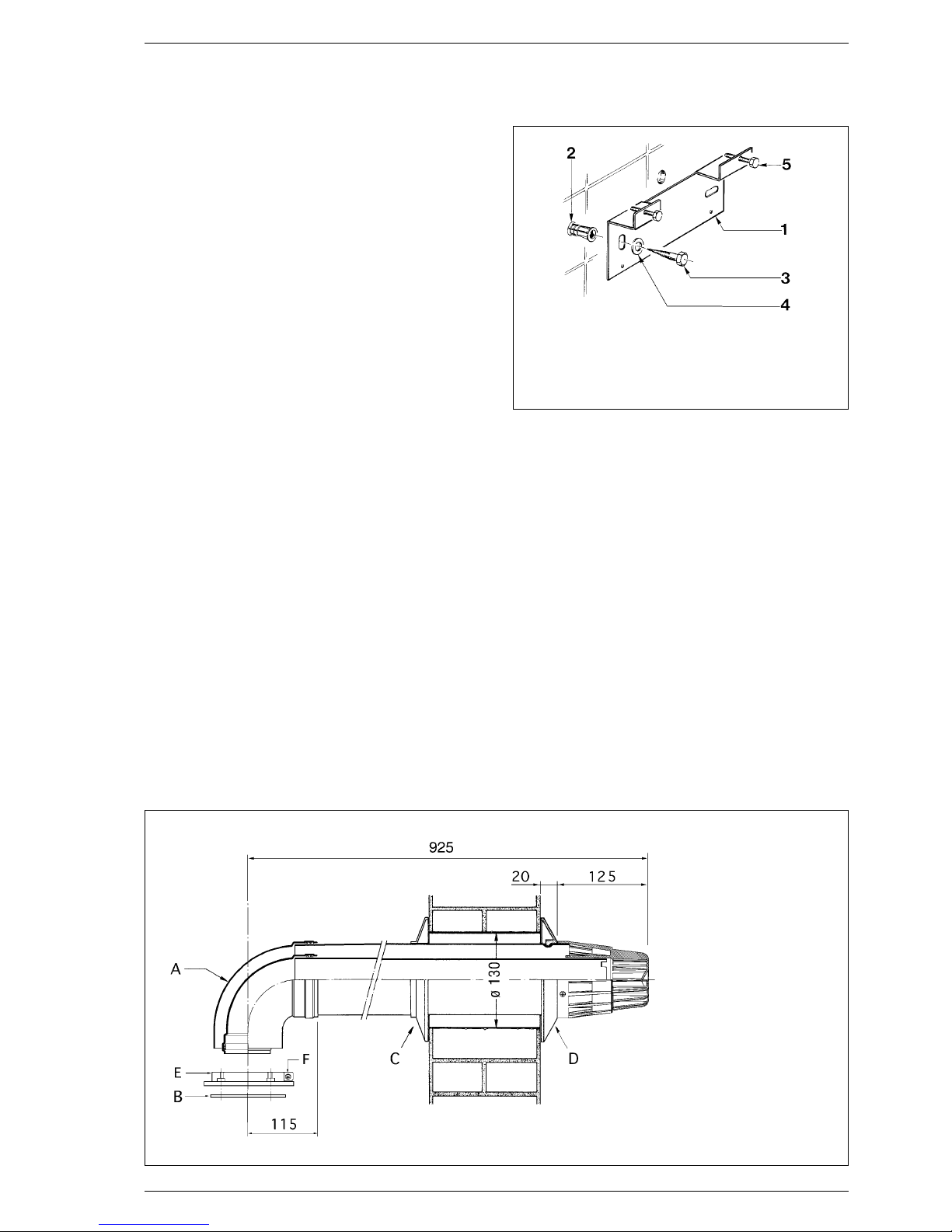
3.1 FIXING THE WALL MOUNTING BRACKET
Before installing the appliance ensure that the chosen
location is suitable (section 2.2) and that the requirements
for flue position, (section 2.3), and minimum clearances,
(
Table 2
) are satisfied. These minimum clearances are
essential to provide access for servicing, and are included on
the wall mounting templates.
– Open the paper wall mounting templates. If a rear flue is to
be used, discard the side templates and secure the rear
template in the desired position. For a side flue application,
secure both the rear and appropriate side template in
position.
– Mark the position of the two wall mounting bracket fixing
holes and the flue/air duct hole on the appropriate wall(s).
– Remove the template(s) and drill the two fixing holes using
a 10 mm masonry drill. Fit the plastic plugs provided.
– Cut the hole in the wall for the flue/air duct. The diameter
should not be less than 100 mm (4 in) and must be
horizontal. Refer to fig. 12-14.
– Accurately measure the wall thickness, and note this
dimension for later use.
– Secure the wall mounting bracket in position using the
screws provided. Ensure that it is the correct way up, as
indicated in fig. 8.
3.2 HANGING THE BOILER
– Lift the appliance into position. The upper cross member
locates onto the wall mounting bracket.
– Screw in the wall mounting bracket adjusting screws until
the appliance is secure and vertical.
3.3 COAXIAL DUCT ø 60/100
The air inlet-smoke outlet assembly ø 60/100 is supplied in a
kit code 8084811. For the assembly follow what is indicated
in figure 9:
– Make a hole in the wall sufficiently large to allow an inser-
tion of a PVC pipe 130 mm ø of the same length as the
thickness of the wall it has to pass through. Then fix the
PVC pipe in place using cement mortar.
– Before to inser t the duct in the wall hole fit in position the
3 INSTALLING THE BOILER
Fig. 8
KEY
1 Wall mounting bracket
2 Plastic wall plug (2 Off)
3 Woodscrew (2 Off)
4 Washer (2 Off)
5 Adjustment screw (2 Off)
KEY
A Elbow 90°
B Sponge-rubber
gasket ø 125/95
C White inner duct
D Grey outer duct
E Junction collar
F Screw
NOTE: The kit can be extended
to a maximum measure of
800 mm horizontal.
Fig. 9

15
outer wall seal (D).
– Push the tube outwards until the gasket comes out. Pull the
pipe inwards bringing the ring to rest on the wall.
– Slide the inner ring (C).
– Insert the inner/outer duct into the elbow (A) until the
ducts touch the inner part of the elbow where the diameter
becomes smaller.
– Fit the sponge-rubber gasket (B) to the collar (E).
– Secure the collar (E) to the sealed chamber using the four
screws provided.
– Insert the elbow (A) into the collar (E) tightening the screw
(F).
With the curve supplied in the kit the maximum horizontal
length of the flue must not exceed 3,6 metres.
The diagrams in fig. 10 illustrate a number of examples of different coaxial outlets.
NOTE: The air intake-flue outlet assembly must slope slightly
downwards to prevent rain water getting into the boiler.
3.3.1 Coaxial flue diaphragm ø 60/100
The boiler is supplied as standard with a ø 86 diaphragm.
With outlet type C12, install diaphragm ø 86 only if the
coaxial flue is less than 1 metres long.
For C32 discharge options, it is necessary to order the optional diaphragm separately ø 87,5 (cod. 6028624) and use it
in accordance with the instructions provided in figure 11.
C12
C32
C42
3
1
2
7
6
4
3
2
min 1,3 m - max 5 m
8
x
y
x + y = max 3,5 m "25"
x + y = max 3,0 m "30-35"
max 3,5 m "25"
max 3,0 m "30-35"
KEY
1 Coaxial flue kit L. 810
code 8084811
2 a Extension L. 1000 code 8096103
2 b Extension L. 500 code 8096102
3 Vertical extension
L. 200 code 8086908
4 Additional 90° curve code 8095801
6 Ar ticulated tile code 8091300
7 Roof outlet terminal
L. 1284 code 8091200
8 Vertical condensation collector
L. 200 cód. 8092803
IMPORTANT:
– Each additional 90° curve installed
reduces the available length by 1
metre.
– Each additional 45° curve installed
reduces the available length by 0.50
metres.
– It is advisable to assemble the conden-
sation collector (8) on vertical segments exceeding 2.5 metres in length
and to limit maximum length to 4
metres.
Fig. 10
x + y = max 3,6 m
max 3,6 m

16
With outlet type C12, install diaphragm ø 86 only if
the coaxial flue is less than 1 metres long.
With outlet type C32, use the following diaphragms, depending on flue length and without
any additional curves:
Installations with vetrical Installations with vertical condensation
extension L. 200 code 8086908 collector code 8092803
Diaphragm Diaphragm Without Diaphragm None
ø 86
optional ø 87,5
diaphragm optional
ø 87,5
diaphragm
(cod. 6028623) (cod. 6028624) (cod. 6028624)
L min = 1,3 m L min = 2,5 m L min = 4 m L max = 2,5 m L min = 2,5 m
L max = 2,5 m L max = 4 m L max = 5 m L max = 4 m
Fig. 11
3.4 COAXIAL DUCT ø 80/125
The air inlet-smoke outlet assembly ø 80/125 is supplied in a
kit code 8084830. For the assembly follow what is indicated
in figure 12:
–Make a hole in the wall sufficiently large to allow an insertion
of a pipe ø 125 mm.
–Before to insert the duct in the wall hole fit in position the
outer wall seal (D).
–Push the tube outwards until the gasket comes out. Pull the
pipe inwards bringing the ring to rest on the wall.
–Slide the inner ring (C).
–Insert the adapter (G) to the coaxial duct.
–Insert the adapter to the elbow (A).
–Fit the sponge-rubber gasket (B) to the collar (E).
–Secure the collar (E) to the sealed chamber using the four
screws provided.
–Insert the elbow (A) into the collar (E) tightening the screw
(F).
With the curve supplied in the kit the maximum horizontal
length of the flue must not exceed 6 metres (vers. “Format
80 B”) - 7 metres (vers. “Format 100 B”).
The diagrams in fig. 13 illustrate a number of examples of different coaxial outlets.
NOTE: The air intake-flue outlet assembly must slope slightly
downwards to prevent rain water getting into the boiler.
1055
295
115
ø 125
B
F
E
A
G
C
D
95
KEY
A Elbow 90°
B Sponge-rubber
gasket ø 125/95
C White inner duct
D Grey outer duct
E Junction collar
F Screw
G Adapter
Fig. 12

17
C12
C32
C42
2
7
6
4
1
2
min. 4 m - max 6 m "25"/7 m "30"
8
x
y
x + y = min. 3,6 m/max 6 m "25"
x + y = min. 3,6 m/max 7 m "30"
5
5
3
8
2
1
1
min. 3,6 m - max 6 m "25"/7 m "30"
Fig. 17
IMPORTANT:
– Each additional 90° curve installed reduces the available length by 1 metre.
– Each additional 45° curve installed reduces the available length by 0.50 metres.
– The insertion of the recovery condenses (8) is obligatory in the tipologia of C32 download.
– The insertion of the recovery condenses (8) is obligatory in the tipologia of C42 download
when the section “y” is advanced to 2,5 metres.
KEY
1 Coaxial flue kit code 8084830
2 Extension L. 1000 code 8096130
3 Vertical extension L. 200 ø 60/100 code 8086908
4 a Additional 90° curve code 8095820
4 a Additional 45° curve code 8095920
5 Adapter from ø 80/125 code 8093120
6 Ar ticulated tile code 8091300
7 Roof outlet terminal L. 1284 code 8091200
8 Vertical condensation collector L. 200 ø 60/100 cód. 8092803

18
3.5 SEPARATE DUCTS
(Optional alternative twin pipe system)
When installing the separate ducts, comply with the
requirements of the current standards, as well as the
following practical pointers:
– With direct intake from outside, when the pipe is longer
than 1 m, you are recommended to insulate the piping so
as to prevent the formation of condensation on the outside
of the piping during particularly cold periods of the year.
– With the outlet pipe outside the building or in cold indoor
environments, insulation is necessary to prevent burner
ignition failure. In such cases, provide for condensate
drainage.
– If a segment of the flue passes through a flammable wall,
this segment must be insulated with a glass wool pipe
insulator 30 mm thick, with a density of 50 kg/m
3
.
The maximum overall length of the intake and exhaust
ducts depends on the head losses of the single fittings
installed and can reach approximately the following
horizontal measures:
– 15 m for “Format 80 B” model,
– 21 m for “Format 100 B” model.
For head losses in the fittings, refer to
Table 7.
1
2
3
4
6
165
110
165
K
ø 80
ø 80
100
92
Fig. 18
KEY
1 Sponge-rubber gasket
ø 125/95
2 Fixing screw
3 Smoke outlet flange
4 Air intake diaphragm
6 Manifold with intakes
80 B 100 B
Kmm 185 210
Fig. 18/a
N° segments Total load loss mm H2O
to remove 25 BF 30 BF
none 0 ÷ 3,0 0 ÷ 3,0
n° 1 3,0 ÷ 4,0 3,0 ÷ 4,0
n° 2 4,0 ÷ 5,0 4,0 ÷ 5,0
n° 3 5,0 ÷ 6,0 5,0 ÷ 6,0
n° 4 6,0 ÷ 7,0 6,0 ÷ 7,0
n° 5 6,0 ÷ 7,0 7,0 ÷ 8,0
n° 6 7,0 ÷ 8,0 8,0 ÷ 9,0
n° 7 7,0 ÷ 8,0 9,0 ÷ 10,0
n° 8 8,0 ÷ 9,0 10,0 ÷ 11,0
n° 9 8,0 ÷ 9,0 11,0 ÷ 12,0
n° 10 - 12,0 ÷ 13,0
without diaphragm 9,0 ÷ 10,5 13,0 ÷ 14,0

19
3.5.1 Separate flue accessories
Part No 8089904 is supplied for this purpose. The sectored
diaphragm is to be used according to the maximum head loss
allowed in both pipes, as given in fig. 18/a.
3.5.2 Use of air intake (fig. 19)
To use the air intake in this type of outlet you must perform
the following operations:
–
Remove the base of the air intake, using a tool to cut it off (a);
–Overturn the air intake (b) and replace the seal (5) with the
seal supplied in the kit code 8089904;
–Insert the intake diaphragm supplied in the kit code
8089904, pushing it in until it is in contact with the seat;
You can now insert the extension or curve in its housing to
complete the intake (you need not use any seat or sealant).
3.6 WATER CONNECTIONS
3.6.1 Central heating connections
–
Fit the two C.H. isolation valves using the gaskets supplied to
the flow and return connections as shown in fig. 2. The pipe
connections are labelled on the lower part of the boiler.
– Connect the C.H. pipework as required.
3.6.2 D.H.W. connections
– Fit the D.H.W. isolation valve to the cold water inlet
connection as shown in fig. 2.
– Fit the union connection to the D.H.W. outlet.
– Connect the D.H.W. pipework as required.
3.7 GAS CONNECTIONS
– Screw the gas cock into the internal thread in the gas inlet
connection using a suitable jointing compound.
– Connect the gas supply pipe.
3.8 SAFETY VALVE CONNECTION
– The appliance safety valve is located towards the R.H.S. of
the boiler and the discharge pipe is supplied loose. Remove
the two selftapping screws and lower the control box to
improve access.
– Connect the discharge pipe to the valve outlet, and extend
the pipe to ensure that any discharge from the safety valve
is safely routed to a drain. The discharge pipe should be a
minimum of 15 mm copper, and must avoid sharp corners
or upward pipe runs where water may be retained.
3.9 WIRING INSTRUCTIONS
(Refer to sections 2.6 - 2.7 and fig. 20)
– Support the valve whilst tightening the nut and olive to
avoid damage to the technil assembly.
– Disconnect the electric power supply before performing
any work.
– Remove the three screws (9) locking the control panel in place
and pull the panel forward until it can be tilted downward.
– To access the components of the electrical panel, unscrew
the four screws holding the protective guard in place (6).
Fig. 19
a
b
5
IMPORTANT: The three housings on the
diaphragm permit assembly of the air
intake in one position only (with numbers
toward inside the boiler).
TABLE 7
Accessories ø 80 Load loss (mm H2O)
“80 B/100 B”
Intake Outlet Roof out. Intake
90° curve MF 0.30/0.30 0.40/0.50 –
45° curve MF 0.20/0.20 0.30/0.40 –
Extension L. 1000 (horizontal) 0.20/0.20 0.30/0.40 –
Extension L. 1000 (vertical) 0.30/0.30 0.20/0.30 –
Outlet terminal – 0.30/0.40 –
Intake terminal 0.10/0.10 – –
Manifold 0.20/0.30 – –
Roof outlet terminal L.1390 – – 0,50/0.60
Condensation collection T – 1.00/1.10 –

20
– To gain access to connector “TA”, remove the control
panel cover (7) and connect the room stat to the
terminals 10-11 after having removed the jumper.
The thermostat or timer-thermostat, recommended for
better room temperature control, must be class II as
specified by standard EN 60730.1 (clean contact).
– Carry out electrical system checks through a suitable test
meter: earth continuity, polarity, resistance to earth and
short circuit.
– Re-secure control box.
– Ensure sufficient length of cable to allow access to control
panel.
8
1
25
4
7
6
Fig. 20
KEY
1 Temperature and pressure gauge
2 Easy-Stat Receiver housing (8092221)
4 Main PCB
5 Ear th faston
6 Control panel protection
7 Cover (TA)
8 Connector (TA)
ATTENTION: After having removed the three fixing
screws, tilt the panel downward to gain access
.

21
SIME SUPPORT THE BENCHMARK INITIATIVE
All relevant sections of the logbook must be filled in at the
time of installation and thereaf ter service information on the
back page of the logbook. Commissioning of the boiler is not
complete until the logbook is filled in.
Before commissioning the appliance, the whole gas
installation including the meter MUST be purged and tested
for gas soundness in accordance with BS6891.
IMPORTANT: open all doors and windows, extinguish naked
lights, and DO NOT SMOKE whilst purging the gas line.
Before commencing the commissioning procedure, ensure
that the gas service cock is turned on, the electricity supply
is isolated, and that the D.H.W. and C.H. isolation valves are
in the closed position.
4.1 FILLING THE WATER SYSTEM
– Open the C.H. flow and C.H. return valves (20 - 19 fig. 2).
– Loosen the automatic air vent cap (11 fig. 2).
– Open all radiator valves and system air vents. Fill the
system with water using one of the approved methods
described in section 2.9 to about 0.5 bar greater than the
system design pressure. Close all air vents. Do not close
the A.A.V. the one near the pump!
– Check the system for water soundness.
– Completely drain the appliance and heating system,
thoroughly flush the system, and refill the system design
pressure to BS 7593.
– Open the D.H.W. inlet valve, open any hot tap, clear of air
bubbles. Close hot tap.
4.2 COMMISSIONING THE BOILER
– Loosen the screw and connect a pressure gauge to the
burner pressure test point on the gas valve (fig. 21).
– Ensure that the rotary switch on the facia panel is set to
the summer position “ ” (D.H.W. Only), turn the D.H.W.
thermostat to maximum (fully clockwise), and turn on the
electrical supply. Fully open any D.H.W. tap and the burner
will light.
– Allow the boiler to run for at least 5 minutes and check
that the burner pressure is as stated in section 1.3. The
D.H.W. burner pressure is factory set and should not
require adjusting. If the burner pressure is low, check that
the appliance has not begun to modulate (this will occur if
the D.H.W. flow rate is low. If modulation is suspected,
open all D.H.W. taps to maximise flow and recheck burner
pressure). Check also the inlet pressure with the burner
alight; this should be 20 mbar +/– 1.0 mbar standing
pressure & the working inlet pressure limited to a loss no
greater than 1.0 mbar for natural gas. If it is necessary to
adjust the D.H.W. burner pressure the method is
described in section 8.6.
– Reduce the D.H.W. draw off rate to the minimum
necessary to maintain the burner alight by carefully
adjusting the D.H.W. inlet valve and check that the burner
pressure decreases in response to D.H.W. temperature
rise. Fully open the inlet valve.
– Close the D.H.W. tap and ensure that the burner is
extinguished and the pump stops.
4 COMMISSIONING AND TESTING
BURNER PRESSURE
TEST POINT
Fig. 21

22
4.5 FINAL CHECKS
– Re-light and test for gas soundness.
– Re-fit the casing front panel and securing brackets.
– Set the C.H. and D.H.W. potentiometers to the required
settings.
– Ensure that the time clock is set at the desired time
periods. Set the room thermostat (if fitted) to the required
setting.
4.6 USER’S INSTRUCTIONS
Upon completion of commissioning and testing the system,
the installer should:
– Give the “Users Instructions” to the householder and
emphasise their responsibilities under the “Gas Safety
(Installation and Use) Regulations 1996 (as amended)”.
– Explain and demonstrate the lighting and shutdown
procedures.
– Advise the householder on the efficient use of the system,
including the use and adjustment of all system controls for
both D.H.W. and C.H.
– Advise the user of the precautions necessary to prevent
damage to the system, and to the building, in the event of
the system remaining inoperative during frost conditions.
– Explain the function of the boiler overheat thermostat, and
how to reset it.
Emphasise that if cut-out persists, the boiler should be
turned off and the installer or service engineer consulted.
– Stress the importance of an annual service by a
registered heating engineer.

23
Failure to install and commission according to the manufacturer’s instructions and complete this Benchmark Commissioning Checklist will invalidate the warranty. This
does not affect the customer’s statutory rights.
If yes, and if required by the manufacturer, has a water scale reducer been fitted?
CONDENSING BOILERS ONLY
The condensate drain has been installed in accordance with the manufacturer’s instructions and/or BS5546/BS6798 Yes
If the condensate pipe terminates externally has the pipe diameter been increased and weatherproof insulation fitted? Yes

24
Service Record
It is recommended that your heating system is serviced regularly and that the appropriate Service Interval Record is completed. This is also a condition
of any extended warranty offered.
Service Provider
Before completing the appropriate Service Record below, please ensure you have carried out the service as described in the
manufacturer’s instructions.
Always use the manufacturer’s specified spare part when replacing controls.
Date:
Engineer Name:
Company Name:
Telephone No.
Gas Safe Register No.
Comments:
Signature:
Date:
Engineer Name:
Company Name:
Telephone No.
Gas Safe Register No.
Comments:
Signature:
Date:
Engineer Name:
Company Name:
Telephone No.
Gas Safe Register No.
Comments:
Signature:
Date:
Engineer Name:
Company Name:
Telephone No.
Gas Safe Register No.
Comments:
Signature:
Date:
Engineer Name:
Company Name:
Telephone No.
Gas Safe Register No.
Comments:
Signature:
Date:
Engineer Name:
Company Name:
Telephone No.
Operative ID No.
Comments:
Signature:
Date:
Engineer Name:
Company Name:
Telephone No.
Gas Safe Register No.
Comments:
Signature:
Date:
Engineer Name:
Company Name:
Telephone No.
Gas Safe Register No.
Comments:
Signature:
Date:
Engineer Name:
Company Name:
Telephone No.
Gas Safe Register No.
Comments:
Signature:
Date:
Engineer Name:
Company Name:
Telephone No.
Gas Safe Register No.
Comments:
Signature:
Service 1 Service 2
Service 3 Service 4
Service 5 Service 6
Service 7 Service 8
Service 9 Service 10

To ensure continued efficient operation of the appliance, it is
recommended that it is checked and serviced as necessary
at regular intervals. The frequency of servicing will depend
upon the particular installation conditions and usage but in
general once a year should be adequate.
It is the law that any service work must be carried out by
registered personnel (C.O.R.G.I.). Before commencing any
service operation, ISOLATE the mains electrical supply, and
TURN OFF the gas supply at the main service cock. Service
the appliance by following the full procedure detailed below.
5.1 MAIN BURNER ASSEMBLY
– Remove the casing as showed in fig. 23.
– Remove the 8 fixing screws securing the sealed chamber
front panel then remove the panel.
– Unscrew the 7 screws securing the combustion chamber
front panel and remove the panel, taking care not to
damage the insulation.
– Remove the electrode by unscrewing it from the burner
manifold.
– Unscrew the burner manifold union and locking nut. Lift
the front of the burner to disengage manifold thread and
then lift the burner clear.
– Remove the burner manifold by disconnecting the four
screws.
– Inspect and if necessary, clean the injectors, electrodes,
and the main burner bars.
5.2 FAN ASSEMBLY
– Disconnect the electrical connections to the fan. Note the
position of the earth conductor.
– Remove the three screws securing the fan.
– Tilt the fan forwards and remove in a downwards direction.
– Inspect the fan assembly and clean if necessary.
5.3 BITHERMAL EXCHANGER
– Inspect the bithermal exchanger, and clean if necessary.
5.5 CHIMNEY SWEEP FUNCTION
(combustion analysis)
To carry out the verification of combustion in the boiler turn
the selector and stop on the position ( ) until the
green/orange led starts to flash intermittently.
From that moment the boiler will start functioning in heating
mode at the maximum power, with switching off at 80°C and
restarting at 70°C.
Before activating the chimney sweep function make sure
that the radiator valves or eventual zone valves are open.
The test may be carried out also during D.H.W. mode.
To do so it is enough, after having activated the chimney
sweep function, to take some hot water from one or more
outlets.
Even in this condition the boiler functions at the maximum
temperature always with the primary controlled between
80°C and 70°C. During the entire duration of the testing the
hot water taps must remain open.
After verifying the combustion the boiler should be switched
off by placing the selector on the OFF position; then return the
selector to the desired function.
5 ROUTINE SERVICING INSTRUCTIONS
8 SEALED CHAMBER SCREWS
3 FAN FIXING SCREWS
MAIN EXCHANGER
7 COMBUSTION CHAMBER
FRONT PANEL SCREWS
BURNER MANIFOLD UNION
Fig. 24
1
2
Fig. 23
SCREWS
25

26
ATTENTION: After about 15 minutes, or once the hot water
request has been fulfilled, the chimney sweep function
automatically deactivates.
5.6 RE-ASSEMBLY
– Re-assemble all the components in reverse order and
replace all the gaskets fitted in the gas line.
Ensure that all seals are correctly fitted and that the
pressure sensing line is correctly fitted.
Check that the fan earth connection is correctly re-fitted.
Note that the fan polarity (Line and Neutral) is immaterial.
– Check for gas soundness before fitting the casing.
5.7 RE-COMMISSIONING
– Turn on the gas supply, and check for gas soundness whilst
the appliance is running.
– Check the operation of the appliance in both C.H. and
D.H.W. mode and ensure in both cases that the burner
pressure after at least 5 minutes running is as stated on
the data plate or in
Table 3
.
Adjust if necessary as described in section 8.
When any service or replacement of electrical components
which has required the breaking and re-making of electrical
connections has taken place, the following tests must be
repeated:
– earth continuity;
– short circuit;
– polarity;
– resistance to earth.

27
6.1 EARTH CONTINUITY CHECK
Appliances must be electrically disconnected, meter set on Ω
(ohm) x 1 scale and adjust zero if necessary. Tests leads from
any appliance earth point (e.g. inside control box) see wiring
diagrams (section 7) to earth pin on plug. Resistance should
be less than 1Ω (ohm). If the resistance is greater than 1Ω
(ohm) check all earth wires for continuity and all contacts are
clean and tight. If the resistance to earth is still greater than
1Ω (ohm) then this should be investigated futher.
6.2 SHORT CIRCUIT CHECK
Switches turned FULL ON - meter set on Ω (ohms) x 1 scale.
Test leads from L to N on appliance terminal block, if meter
reads 0 then there is a short circuit.
Meter set on Ω (ohm) x 100 scale. Repeat it with leads from
L to E. If meter reads less than infinity (∞) there is a fault.
NOTE: Should it be found that the fuse has failed but no
fault is indicated, a detailed continuity check (i.e. by
disconnecting and checking each component) is required to
trace the faulty component.
It is possible that a fault could occur as a result of local
burning/arcing but no fault could be found under test.
However, a detailed visual inspection should reveal
evidence of burning around the fault.
6.3 POLARITY CHECK
Appliance reconnected to mains supply and meter set on
300 V ac scale. Test at appliance terminal block.
– Test leads from L to N meter reads approx.: 240 V ac.
– Test leads from L to E “ ” meter reads approx. 240 V ac.
– Test leads from N to E “ ” meter reads from 0 to 15 V ac.
6.4 RESISTANCE TO EARTH CHECK
Appliance must be disconnected from main supply and meter
on Ω (ohm) x 100 scale.
All switches including thermostat on test leads from L to E - if
meter reads other than infinity (∞) there is a fault which
should be isolated. A detailed continuity check is required to
trace the faulty component.
IMPORTANT:
These series of checks are the first electrical checks to be
carried out during a fault finding procedure. On completion
of the service/fault finding task which has required the
breaking and remaking of electrical connections then the
checks 6.1 Earth continuity, 6.3 Polarity and 6.4
Resistance to earth must be repeated.
6.5 FAULT FINDING LEDS
The indicator leds signalling irregular and/or incorrect
operation of the equipment are indicated in fig. 26.
Before commencing any service operation, ISOLATE the
mains electrical supply, and TURN OFF the gas supply at the
main service cock. It is the law that any service work must be
carried out by registered personnel (Gas Safe Register).
6 FAULT FINDING
Fig. 26
Bi-colour green led off if power is cut-off.
Bi-colour orange led: C.H. sensor (SM) fault.
Green led flashing: fan/smoke pressure switch failure.
Orange led flashes if water pressure is insuf ficient.
Flashing red led indicates a problem in the tap water probe (SS).
Red led on, ignition lock-out/safety and smokes stats
tripped: turn the selector switch briefly to the position
marked ( ) to restore functioning

28
6.6 C.H. MODE - FAULT FINDING
Start from cold Rotary switch set to WINTER position.
Room thermostat (if fitted) calling for heat and all D.H.W. taps off.
C.H. thermostat set to maximum position.
Clock in the on position.
NOTE:
After completing fault finding reset the room thermostat (if fitted) to the required setting. If the appliance will not function
check the wiring to the clock and if necessary, replace the clock.
Is there power
at the external
socket?
Make
power
available
Does
the pump
start?
Does
the fan
start?
Turn the clock
in the right
position
Is fuse
at mains
plug OK?
Is the clock in
the correct
band time?
Is there voltage
available
to the fan?
Replace
the clock
Replace fuse in
mains plug
Check the
time clock does
his contacts
open and close
when the clock
turns?
Replace
the fan
Make it free to
rotate
Put a jumper
on the room
thermostat
connection
Check the
power supply
cable
Is pump shaft
free to rotate?
Is there voltage
available
to the pump?
Replace
the pump
Check pump
connection
Does the boiler
lock-out without
starting the
burner?
The boiler
lock-out
starting
the burner
Is there a spark
at the ignition
electrode?
Is the ionization
probe connected
to the main PCB
and the ground?
Check the
gas supply
Check for continuity between ignition
electrode and igni-
tion transformer
The gap between
ignition electrode
and hood
is correct?
Fit correctly the
ignition electrode
Is the gas
available?
Check the
connection of
the gas valve on
the control board
PCB
Is there voltage at
the gas valve?
Replace the
gas valve
Yes
No
Is there a jumper
on the room
thermostat
connection?
No
Yes
No
Yes
No
Yes
Yes
Yes
Yes
No
Yes
No
Yes
Yes
Yes
No
No
Yes
YesYes
No
No
Yes
No
No
No
No
Yes
No
Verify that the
safety
thermostat
is working
correctly?
Replace the
thermostats
No
Is the
connection of
the safety
thermostats
correct?
Reset the
connection
No
Yes
Restore the
connection
Verify that the
safety
thermostat
is working
correctly?
No
Yes
Yes
Check the
connection of
the thermostat
Replace the
thermostat
No
Yes

29
6.7 D.H.W. MODE - FAULT FINDING
Start from cold - rotary switch set to SUMMER position, D.H.W. thermostat set to maximum, and all D.H.W. taps OFF.
Is there power
at the external
socket?
Make
power
available
Open any tap.
Is there an
adequate flow
rate of D.H.W.
available?
Does
the fan
start?
Is fuses
at mains
plug OK?
Clean or replace
the water flow
switch
Is there voltage
available
to the fan?
Replace fuses in
mains plug
Replace
the fan
Check the
power supply
cable
Does the boiler
lock-out without
starting the
burner?
The boiler
lock-out
starting
the burner
Is there a spark
at the ignition
electrode?
Is the ionization
probe connected
to the main PCB
and the ground?
Check the
gas supply
Check for continu-
ity between ignition
electrode and igni-
tion transformer
The gap between
ignition electrode
and hood
is correct?
Fit correctly the
ignition electrode
Is the gas
available?
Restore the
connection
Check the
connection of
gas valve on
the control board
PCB
Is there voltage at
the gas valve?
Replace the
gas valve
Yes
No
No
Yes
No
Yes
Yes
Yes
Yes
Yes
No
No
Yes
Yes
No
Yes
No
No
No
Yes
No
Yes
Verify that the
safety
thermostat
is working
correctly?
Replace the
thermostats
No
Is the
connection of
the safety
thermostat
correct?
Reset the
connection
No
Yes
Yes
No
Verify that the
safety
thermostat
is working
correctly?
Yes
Check the
connection of
the thermostat
Replace the
thermostat
No

30
7 WIRING & FUNCTIONAL DIAGRAMS
7.1 ILLUSTRATED FLOW WIRING DIAGRAM
CN2 (code 6299977)
CN6 (code 6299974)
CN7 (code 6299973)
CN1
JUMPERS
JP4
WHITE
100 °C SAFETY STAT
C.H. SENSOR (SM)
D.H.W. SENSOR (SS)
GAS VALVE
PRESSURE
SWITCH
ROOM
THERMOSTAT
PUMP
FAN
IGNITION/
IONISATION
ELECTRODE
WATER FLOW
SWITCH ASSEMBLY
TIME
CLOCK
Fig. 27
NOTE:
– The room thermostat may be connected to the terminals 15-16 (CN1) of the “TA” connector after having removed the link.
– To remote control the boiler connect an external clock to the terminals 1-2 (24 V) of the “TA” connector and set the built-
in clock to “constant” mode (see user instructions for details).
JUMPERS POSITION AND FEATURES
JUMPER POSITION AND FEATURE SUPPLY POSITION
CLOSED OPEN
JP4 - METANO/GPL Ready to function with LPG Ready to function with natural gas Open

8.1 BITHERMAL EXCHANGER
– Remove the fan as described in section 8.3.
–
Disconnect the pressure sensing pipe from the flue box, lift the
collector hood assembly, tilt forwards, and remove the hood.
– Isolate the C.H. flow and return valves.
– Drain the bithermal exchanger using the drain cock (at the
bottom RHS of the appliance)
– Unclip the bithermal exchanger securing clips and
unscrew completely the expansion vessel nut.
– Disconnect the pipes from the exchanger and lift out the
heat exchanger.
– Re-assemble in reverse order, ensuring that the bithermal
exchanger seals and clips are correctly located and that
the pressure sensing pipe is correctly re-fitted. The fan
polarity is not important except the earth conductor (G/Y
which is marked on the appliance).
– Refill, and re-commission the system as described in
section 4.
8.2 COMBUSTION CHAMBER INSULATION
The design of this appliance is such that the rear and side
insulation should not require replacement unless
mechanically damaged.
IMPORTANT: When handling insulation panels, take care to
avoid producing or inhaling dust particles. When removing
old or damaged insulation panels, dampen with water to
minimise dust.
To replace the insulation front panel, proceed as follows:
– remove the combustion chamber front panel as described
in section 5.1;
– replace the front insulation panel and glue it into position
on the front panel using the glue supplied. Re-assemble in
reverse order.
Should the rear or side panels become damaged, replace
them as follows.
– remove the heat exchanger as described in section 8.1;
–
remove the side insulation panels followed by the rear panel;
– re-assemble in reverse order, refill, and recommission the
system as described in section 4.
8.3 FAN ASSEMBLY
– Remove the casing front panel and sealed chamber front
panel as described in section 5.1.
– Disconnect the electrical connections and the pressure
sensing pipes to the fan. Note the position of the earth
conductor.
– Unscrew the three screws securing the fan.
– Drop and tilt the fan forwards and remove in a downwards
direction.
– Re-assemble in reverse order. Ensure that the earth
connection is correctly refitted. Note that the polarity (Line
and Neutral) is immaterial.
8.4 MAIN BURNER
– Remove the main burner by following section 5.1.
– Transfer the ignition electrode onto the new burner
assembly.
– Re-assemble in reverse order. Check the electrode gaps
(fig. 28) and test for gas soundness.
– Re-commission the appliance as described in section 4.
8.5 IGNITION/DETECTION ELECTRODE
– Remove the casing front panel and sealed chamber front
panel as described in section 5.1.
– Unscrew the single screw securing the electrode in
position, and release the electrode from the burner.
– Remove the electrode and disconnect its cable from the
ignition transformer.
– Replace the electrode and re-assemble in reverse order.
8.6 GAS VALVE
– Remove the casing front panel as described in section 5.1.
– Disconnect the two leads from the modulating solenoid
and disconnect the valve connector (one screw).
– Unscrew the nut between the inlet pipe and the valve.
– Unscrew the burner manifold nut underneath the sealed
chamber, and withdraw the gas valve complete with outlet
pipe.
– Transfer the outlet pipe onto the new gas valve, using a
new gasket (supplied with the valve).
– Fit the new gas valve assembly into the appliance using the
other new gasket supplied on the valve inlet, and re-
assemble in reverse order.
– Re-light the appliance, check for gas soundness, and re-
commission in accordance with section 4.
In addition it will be necessary to set the D.H.W. and C.H. heat
inputs, with reference to fig. 29, as follows:
Note that it is necessary to set the MAXIMUM PRESSURE
FIRST.
– Connect a pressure gauge to the burner pressure test
point.
– Remove the sealing cap of the proportioning unit (C) by
rotating it ⁄ turn anticlockwise.
– Adjust DHW potentiometer to maximum, then fully open
any DHW tap to light the boiler.
– Using a 10 mm spanner, turn nut (B) to attain the
maximum pressure in
Table 3
.
Turn the nut clockwise to increase or anti-clockwise to
decrease the burner pressure.
31
8 REPLACEMENT OF PARTS
Fig. 28
4
± 0.5
IGNITION/DETECTION
ELECTRODE

– Turn the main selector switch on and off a few times (with
the hot tap still open) and check that the pressure returns
to the correct (set) maximum value (as in
Table 3
).
– Set the minimum burner pressure by first isolating the
electricity supply and disconnecting one of the modulating
solenoid leads, then restore the electricity supply and fully
open a DHW tap to light the appliance at minimum gas
rate.
– Set the minimum pressure with reference to
Tables 3
by
holding nut (B) in position with a 10 mm spanner and
rotating the plastic screw (A) with a screwdriver until the
correct pressure is obtained. Turn the screw clockwise to
increase the pressure or anti-clockwise to decrease it. It is
essential that the max pressure has been set prior to
adjusting the minimum pressure. Check that the minimum
pressure is correctly set by turning on and off the D.H.W.
inlet valve several times and ensuring that the pressure
returns to that previously adjusted;
– Isolate the power supply, re-connect the modulation lead,
restore the power and re-check the maximum pressure,
then re-fit the plastic cover (1).
– Reduce the D.H.W. draw off rate to the minimum nec-
essary to maintain the burner alight by carefully adjusting
the D.H.W. Inlet valve and check that the burner pressure
decreases in response to D.H.W. temperature rise. Fully
open the inlet valve;
– Close the D.H.W. tap and ensure that the burner is
extinguished and the pump stops.
– Adjust the Central Heating maximum pressure as
described in section 4.3, then complete the recommissioning as described in 4.4 and 4.5.
8.7 AIR PRESSURE SWITCH
– Remove the casing front panel and sealed chamber front
panel as described in section 5.1.
– Disconnect the pressure sensing pipe from the switch.
– Remove the switch (two screws) and fit the new one.
– Transfer the electrical connections one at a time (to
ensure that they are not incorrectly re-fitted) to the new
switch.
– Re-assemble in reverse order referring to the wiring
diagrams (section 7) if necessary. Ensure that the
pressure sensing lead is correctly connected to the low
pressure connection on the pressure switch (marked P2).
8.8 SAFETY THERMOSTAT
The safety thermostat is situated on the flow pipe (3 fig. 3).
– Remove the casing front panel as described in section 5.1.
– Disconnect the two limit thermostat wires.
– Unscrew the two limit thermostat fixing screws and
remove the thermostat.
– Replace the thermostat and spread heat sink compound
(supplied) over the base of the new one.
– Re-assemble in reverse order (Polarity is immaterial).
8.9 THERMISTOR
The thermistor is placed over the main exchanger.
– Remove the casing front panel as described in section 5.1.
– Isolate the C.H. flow and return valves (20 - 19 fig. 2), and
drain the appliance through the drain plug (16 fig. 2).
– Pull off the electric connection, and unscrew the
thermistor from the exchanger.
– Replace the thermistor and re-assemble in reverse order.
Table 8
shows the resistance values (Ω) that are obtained on
the sensor as the temperature varies.
8.10 DRIVER PCB
– Remove the casing front panel as described in section 5.1.
– Open the control panel protecting cover by removing the
four fixing screw.
– Pull off the potentiometer knobs.
– Release the PCB (6 screws), transfer all connections onto
the new PCB, and re-assemble in reverse order.
8.11 PUMP MOTOR
– Remove the casing front panel as described in section 5.1.
– Unplug the electrical connection plug.
– Isolate the C.H. flow and return valves (20 - 16 fig. 2), and
drain the appliance through the drain plug (16 fig 2).
– Unscrew the four fixing screws on the motor.
– Replace the pump motor and re-assemble in reverse
order. If the new pump is fitted with a speed adjuster,
ensure that the speed is set to maximum.
–
Refill and commission the system as described in section 4.1.
8.15 C.H. EXPANSION VESSEL
Replacement is not recommended if a rear flue outlet is used
or if the clearance above the casing is less than 300 mm.
– Remove the casing front panel as described in section 5.1.
32
Temperature (°C) Resistance (Ω)
20 12,090
30 8,313
40 5,828
50 4,161
60 3,021
70 2,229
80 1,669
TABLE 8
KEY
A Plastic screw
BNut
C Sealing cap
Fig. 29

33
– Isolate the C.H. flow and return valves (20 - 19 fig. 2), and
drain the appliance through the drain plug (16 fig. 2).
– Unscrew the expansion vessel union on the C.H. return
pipe.
– If a rear flue outlet is used it is necessary to disengage the
flue and air duct temporarily. Refer to section 3.5.
– Remove the adjusting screws on the wall mounting
bracket thereby allowing the appliance to move slightly
forwards at the top.
– Lift the expansion vessel out of the appliance through the
top.
– Replace the expansion vessel and re-assemble in reverse
order. Re-pressurise and re-commission the system as
described in section 4.1.
8.16 PRESSURE/TEMPERATURE GAUGE
– Remove the casing front panel as described in section 5.1.
– Isolate the C.H. flow and return valves (20 - 19 fig. 2).
– Drain the appliance through the drain point (16 fig. 2).
– Remove the circlip securing the pressure sensor to the
hydraulic group and pull out the sensor.
– Remove the fixing spring of the thermometer bulb from
the C.H. flow pipe.
– Squeeze the gauge to depress the retaining clips, then
ease the gauge forwards.
– Reassemble in reverse order.
Refill and re-commission the system as described in
section 4.1.
8.17 SAFETY VALVE
– Remove the casing front panel as described in section 5.1.
– Isolate the C.H. flow and return valves (20 - 19 fig. 2).
– Drain the appliance through the drain point (16 fig. 2)
– Remove the circlip securing the valve to the hydraulic
group and remove the valve.
– Fit the new safety valve and re-assemble in reverse order.
Refill and re-commission the system as described in
section 4.1.
8.18 AUTOMATIC AIR VENT
– Remove the casing front panel as described in section 5.1.
– Isolate the C.H. flow and return valves (20 - 19 fig. 2).
– Drain the appliance through the drain point (16 fig. 2).
– Remove the circlip securing the automatic air vent to the
hydraulic group.
– Fit the new automatic air vent and re-assemble in reverse
order. Refill and re-commission the system as described in
section 4.1.
8.19 TIME CLOCK
– Pull off the electrical connections at the back of the clock.
– Remove the two screws securing the plastic frame of the
time clock to the facia panel.
– Remove the plastic frame and pull out the time clock.
– Re-assemble in reverse order and test the operation of
the new clock.
– Set it to the desired settings as described in section 4.3.

COD. TYPE DATE PAGE
3820086/318 FORMAT 80B - 100B 26.04.2007 1/4
34
9 EXPLODED VIEWS

35
POSITION CODE DESCRIPTION MODEL NOTE
COD. TYPE DATE PAGE
• Recommended stock par ts - Com ponenti da tenere a scorta
POSITION CODE DESCRIPTION MODEL NOTE
1 6138570 Side frame part
2 6138770 Frame assembly upper support 80
2 A 6138771 Frame assembly upper support 100
3 6255430 Expansion vessel lower support 80
3 A 6255431 Expansion vessel lower support 100
4 • 5139140 Expansion vessel l.7 - 3/8” M 80
4 A • 5139130 Expansion vessel l.8 - 3/8” M 100
5 6146305 Brass Nut 3/8”
6 6288105 Sealed chamber rear panel 80
6 A 6288115 Sealed chamber rear panel 100
7 6119313 Plastic cap
8 6287900 Air/smoke manifold
9 6147406 Air/smoke manifold plug M14x1.5
10 • 6226417 O-ring 3043
11 6242602 Air/smoke manifold screw
12 6248803 Lip seal for Ø 60 pipe
13 6028706 Air/smoke manifold gasket
14 2000716 Screw T.C.B. M4x8
15 5190700 Main burner assembly 80
15 A 5190752 Main burner assembly 100
16 • 6235931 Ignition-ionisation electrode
17 6146301 Brass nut 1/2”
18 6288415 Combustion chamber rear panel 80
18 A 6288416 Combustion chamber rear panel 100
19 6288500 Combust. chamber right hand side panel 80
19 A 6288510 Combust. chamber right hand side panel 100
20 6288600 Combust. chamber left hand side panel 80
20 A 6288610 Combust. chamber left hand side panel 100
21 6139789 Combustion chamber rear insulation 80
21 A 6139790 Combustion chamber rear insulation 100
22 6139774 Combustion chamber side insulation 80
22 A 6139792 Combustion chamber side insulation 100
23 6028707 Air intake gasket
24 6288000 Air intake
25 6257512 Air deflector for separate ducts
26 6174249 Gas/Water heat exchanger 80
26 A 6174250 Gas/Water heat exchanger 100
27 6231356 Temperature sensor
28 6272504 Temperature sensor fixing spring
29 5190601 Smoke chamber assembly 80
29 A 5190611 Smoke chamber assembly 100
30 2016020 Locked nut M4
31 • 6225632 Fan 80
31 A • 6225624 Fan 100
32 2000715 Screw TCB M4x10 AISI 304
33 6288701 Combustion chamber front panel 80
33 A 6288711 Combustion chamber front panel 100
34 6139787 Combustion chamber side insulation 80
34 A 6139788 Combustion chamber side insulation 100
35 6264836 C.H. return pipe 80
35 A 6264837 C.H. return pipe 100
36 • 6226412 O-ring 3068
37 • 6226601 Spring for heat exchanger connection
38 6264767 C.H. flow pipe 80
38 A 6264768 C.H. flow pipe 100
39 2030226 Gasket Ø 10,2x14,8x2
40 • 6146701 100°C safety stat
41 6227012 D.H.W. outlet pipe 80
41 A 6227013 D.H.W. outlet pipe 100
42 • 6226444 O-Ring Ø 13,64x 2,62
43 • 6226617 Spring for heat exchanger connection
44 6227111 D.H.W. inlet pipe 80
44 A 6227112 D.H.W. inlet pipe 100
45 6131430 Magnetic sensor
46 6226612 Pipe fixing double spring
47 6017310 Flexible pipe
48 6226414 O-ring 117 Ø 13,1x2,62 EP851
49 6138870 Frame assembly lower side 80
49 A 6138880 Frame assembly lower side 100
50 6146302 Brass nut 3/4”
51 • 6037504 Water pressure switch
52 6226611 Water rate adjuster fixing spring
53 6281410 Water rate adjuster 11 l/min 80
53 A 6281411 Water rate adjuster 15 l/min 100
54 • 6040201 Pressure relief valve
55 6100202 Ogive for pipe Ø 15
3820086/318 FORMAT 80B - 100B 26.04.2007 2/4

36
POSITION CODE DESCRIPTION MODEL NOTE
COD. TYPE DATE PAGE
• Recommended stock par ts - Com ponenti da tenere a scorta
POSITION CODE DESCRIPTION MODEL NOTE
56 6168401 Locking nut for pipe Ø 15
57 • 6226602 Pipe fixing spring
58 6120510 Nipple 1/2”x1/2” OT
59 2030228 Gasket Ø 17x24x2
60 2030227 Gasket Ø 12x18x2
61 • 6231357 D.H.W. temperature sensor
62 6028705 Gasket EP709 for Dab
63 2000201 Screw M5x40
64 6288200 Sealed chamber side panel
65 6215220 Cables protection bracket
66 6229101 Smoke pressure switch bracket
67 6225724 Air pressure switch 52-62 Pa 80
67 A • 6225710 Air pressure switch 35-45 Pa 100
68 6280500 3-ways junct. with press. test nipple
69 6243820 SIT gas valve type 845 SIGMA
70 6226873 Gas inlet pipe
71 6226952 Pipe connecting gas valve-main burner
72 6146303 Brass Nut 1/8”
73 6289817 Control panel
74 6247360 Cap for time programmer
75 2005201 Screw “HI-LO” TSP 3x12
76 6273210 Guidelight - 2 ways out
77 6217005 Temperature and pressure gauge
78 6230630 Main P.C.B.
79 • 6201505 Trimmer spindle Ø 6
80 • 6201502 Trimmer spindle Ø 6
81 2211610 Ear th faston
82 • 6269810 Ignition cable
83 6289900 Control panel protecting cover
84 6290300 Control panel cable cover
85 6290200 Room stat connection cover
86 6290100 White knob Ø 40
87 6009585 Control panel bracket
88 6290015 Flap door 80
89 2051100 Retaining spring
90 6226605 Fixing spring
91 6288300 Sealed chamber front panel 80
91 A 6288310 Sealed chamber front panel 100
92 6001210 Peephole
93 6287321 Casing 80
93 A 6287331 Casing 100
94 2013302 Fastener for self tapping screw
95 2004510 Screw 8Px7/8”
96 6112420 Control panel screw
97 • 6028623 Air diaphragm Ø 86
98 6142330 Quarter bend 1/2” x 15
99 6177505 Ball cock 3/4” x 22
100 6177506 Ball cock 1/2” x 15
101 6177530 Gas cock 3/4” F x 15
102 6157602 Pressure relief valve drain pipe
103 6257523 Air deflector 100
104 6263911 Fan pressure test point 80
104 A 6263906 Fan pressure test point 100
105 5192200 Gasket for sealed chamber
106 • 5192600 Dab VA55 pump kit 80
106 A • 5192601 Dab VA65 circulating pump kit 100
107 6022004 Copper washer Ø 6
108 6154402 Main burner nozzle NP 130 natural gas
108 A 6154410 Main burner nozzle NP 77 GLP 80
108 B 6154406 Main burner nozzle NP 0,80 100
109 6281521 Flange + OR for Dab pump
111 6281500 Straight fitting 3/4”
112 6281501 Straight fitting 1/2”
113 • 6013101 Automatic air vent
114 • 6149316 Flow water switch assembly
115 6226446 O-ring Dalmar R7
116 • 6017250 Manual air vent 1/4”
117 6296916 By-pass
118 • 6226421 O-ring Dalmar R12
119 6281529 Flow manifold group + OR
120 6281530 Flow/return manifold group
121 6301900 Flow water switch-flow manifold pipe
5187352 Technyl hydraulic group
5191210 Control panel assembly
6127210 Main cable L=2000
3820086/318 FORMAT 80B - 100B 26.04.2007 3/4

37
POSITION CODE DESCRIPTION MODEL NOTE
COD. TYPE DATE PAGE
• Recommended stock par ts - Com ponenti da tenere a scorta
POSITION CODE DESCRIPTION MODEL NOTE
6299973 14 pole Lumberg cable connector CN6
6299974 6 pole Stocko connector CN7
6299977 4 pole Lumberg cable connector CN2
• 5144712 Conversion kit to LPG 80
• 5144716 Conversion kit to LPG 100
• 6233500 Fuse 1.6A main P.C.B.
5184817 Fitting cocks kit
Products reference:
8105400: Format 80B Natural gas
8105401: Format 80B L.P.G.
8105402: Format 100B Natural gas
8105403: Format 100B L.P.G.
Check the correspondence with the boiler data plate.
3820086/318 FORMAT 80B - 100B 26.04.2007 4/4

38
GAS CONVERSION
A kit is supplied upon request complete with the necessary change-over materials for operation with butane gas (G30)
or propane gas (G31). Operate in the following manner for changing over from one gas to another:
– Close the gas cock.
– Slide out the burner unit.
–
Replace the main nozzles (6) supplied in a kit, inserting the copper washer (4). Use a ø 7 spanner to per form this
operation.
–
Remove the “MET/GPL” connector link on the main board and set it on “GPL”.
– To set the values of maximum and minimum gas pressure, follow the instructions given in section 8.6.
When the working pressures have been adjusted, reseal the regulators.
– After the conversion of the boiler, please stick onto the casing panel the plate showing the relevant feeding gas
which is included in the kit.
NOTE: When reassembling components which you have removed, replace gas seals; test all gas connections after
assembly using soapy water or a product made specifically for the purpose, being sure not to use open flame.
Conversion must be performed by authorised personnel only.
KEY
1 Swivel connection 1/2”
2 Locknut 1/2”
3 Burner manifold
4 Washer ø 6.1
5 Burners
6 Nozzle M6
7 Screw
All descriptions and illustrations provided in this manual have been carefully prepared but we reserve the right to make changes
and improvements in our products that may affect the accuracy of the information contained in this manual.


Cod. 6272297 - 02/11 - Documentation Dpt.
Sime Ltd
1a Blue Ridge Park
Thunderhead Ridge
Glasshoughton, Castleford, WF10 4UA
Phone: 0845 9011114
Fax: 0845 9011115
www.sime.ltd.uk
Email: enquiries@sime.ltd.uk
 Loading...