


Supplied By www.heating spares.co Tel. 0161 620 6677
Format C
Installation and
servicing instructions
GB
PLEASE LEAVE THIS INSTRUCTION
WITH THE USER
Supplied By www.heating spares.co Tel. 0161 620 6677
Format 80 C:
Gas Council number 47-719-12
Format 100 C:
Gas Council number 47-719-13
Format 110 C:
Gas Council number 47-719-21
These appliances comply with the S.E.D.B.U.K. scheme, band “D”
SIME COMBINATION BOILERS
Installer checklist
Please remember to carry out the following checks after installation. This will achieve complete customer satis-
faction, and avoid unnecessary service calls. A charge will be made for a service visit where the fault is not due to
a manufacturing defect.
– Has a correct by-pass been fitted and adjusted?
– Has the system been flushed in accordance with the guidelines given in BS7593 “Treatment of water in domes-
tic hot water central heating systems”?
– Is the system and boiler full of water, and the correct pressure showing on the pressure gauge?
– Is the Auto Air Vent open?
– Has the pump been rotated manually?
– Is the gas supply working pressure correct?
– Is the boiler wired correctly? (See installation manual).
– Has the D.H.W. flow rate been set to the customer requirements?
– Has the customer been fully advised on the correct use of the boiler, system and controls?
– Has the log book provided been completed?
Please refer to commissioning instructions for filling in the log book
Note: All CORGI registered installers carry a CORGI ID Card.
You can check your installer is CORGI Registered by calling 01256 372300
IPX4D

Supplied By www.heating spares.co Tel. 0161 620 6677
1 TECHNICAL FEATURES AND DIMENSIONS
1.1 INTRODUCTION . . . . . . . . . . . . . . . . . . . . . . . . . . . . . . . . . . . . . . . . . . . . . . . . . . . . . . . . . . . . . . . . . . . . . . . . . . . . . 1
1.2 DIMENSIONAL DETAILS
1.3 GENERAL DATA . . . . . . . . . . . . . . . . . . . . . . . . . . . . . . . . . . . . . . . . . . . . . . . . . . . . . . . . . . . . . . . . . . . . . . . . . . . . . 2
1.4 HYDRAULIC CIRCUIT . . . . . . . . . . . . . . . . . . . . . . . . . . . . . . . . . . . . . . . . . . . . . . . . . . . . . . . . . . . . . . . . . . . . . . . . . 3
1.5 INTERNAL VIEW . . . . . . . . . . . . . . . . . . . . . . . . . . . . . . . . . . . . . . . . . . . . . . . . . . . . . . . . . . . . . . . . . . . . . . . . . . . . . 4
2 GENERAL REQUIREMENTS FOR INSTALLATION
2.1 STATUTORY REQUIREMENTS . . . . . . . . . . . . . . . . . . . . . . . . . . . . . . . . . . . . . . . . . . . . . . . . . . . . . . . . . . . . . . . . . 5
2.2 BOILER POSITION
2.3 FLUE TERMINAL POSITION
2.4 VENTILATION REQUIREMENTS . . . . . . . . . . . . . . . . . . . . . . . . . . . . . . . . . . . . . . . . . . . . . . . . . . . . . . . . . . . . . . . . 6
2.5 GAS SUPPLY
2.6 ELECTRICITY SUPPLY
2.7 EXTERNAL CONTROLS
2.8 WATER SYSTEMS - GENERAL
2.9 REQUIREMENTS FOR SEALED WATER SYSTEMS
2.10 D.H.W. SYSTEMS . . . . . . . . . . . . . . . . . . . . . . . . . . . . . . . . . . . . . . . . . . . . . . . . . . . . . . . . . . . . . . . . . . . . . . . . . . . . 8
3 INSTALLING THE BOILER
3.1 FIXING THE WALL MOUNTING BRACKET . . . . . . . . . . . . . . . . . . . . . . . . . . . . . . . . . . . . . . . . . . . . . . . . . . . . . . . 9
3.2 HANGING THE BOILER
3.3 FLUE DUCTS PREPARATION
3.4 FLUE AND TERMINAL INSTALLATION . . . . . . . . . . . . . . . . . . . . . . . . . . . . . . . . . . . . . . . . . . . . . . . . . . . . . . . . . . . 10
3.5 SEPARATE DUCTS . . . . . . . . . . . . . . . . . . . . . . . . . . . . . . . . . . . . . . . . . . . . . . . . . . . . . . . . . . . . . . . . . . . . . . . . . . . 12
3.6 WATER CONNECTIONS . . . . . . . . . . . . . . . . . . . . . . . . . . . . . . . . . . . . . . . . . . . . . . . . . . . . . . . . . . . . . . . . . . . . . . . 13
3.7 GAS CONNECTIONS
3.8 SAFETY VALVE CONNECTION
3.9 WIRING INSTRUCTIONS
4 COMMISSIONING AND TESTING
4.1 FILLING THE WATER SYSTEM . . . . . . . . . . . . . . . . . . . . . . . . . . . . . . . . . . . . . . . . . . . . . . . . . . . . . . . . . . . . . . . . . 15
4.2 COMMISSIONING THE BOILER
4.3 SETTING THE C.H. INPUT
4.4 SETTING THE D.H.W. FLOWRATE . . . . . . . . . . . . . . . . . . . . . . . . . . . . . . . . . . . . . . . . . . . . . . . . . . . . . . . . . . . . . . 16
4.5 FINAL CHECKS
4.6 USER’S INSTRUCTIONS
5 ROUTINE SERVICING INSTRUCTIONS
5.1 MAIN BURNER ASSEMBLY . . . . . . . . . . . . . . . . . . . . . . . . . . . . . . . . . . . . . . . . . . . . . . . . . . . . . . . . . . . . . . . . . . . 17
5.2 FAN ASSEMBLY
5.3 HEAT EXCHANGER
5.4 WATER FLOW SWITCH
5.5 CHIMNEY SWEEP FUNCTION . . . . . . . . . . . . . . . . . . . . . . . . . . . . . . . . . . . . . . . . . . . . . . . . . . . . . . . . . . . . . . . . . 18
5.6 RE-ASSEMBLY
5.7 RE-COMMISSIONING
5.8 CLEANING THE C.H. WATER FILTER
CONTENTS

Supplied By www.heating spares.co Tel. 0161 620 6677
6 FAULT FINDING
6.1 EARTH CONTINUITY CHECK . . . . . . . . . . . . . . . . . . . . . . . . . . . . . . . . . . . . . . . . . . . . . . . . . . . . . . . . . . . . . . . . . . 19
6.2 SHORT CIRCUIT CHECK
6.3 POLARITY CHECK
6.4 RESISTANCE TO EARTH CHECK
6.5 FAULT FINDING LEDS
6.6 C.H. MODE - FAULT FINDING . . . . . . . . . . . . . . . . . . . . . . . . . . . . . . . . . . . . . . . . . . . . . . . . . . . . . . . . . . . . . . . . . . 20
6.7 D.H.W. MODE - FAULT FINDING . . . . . . . . . . . . . . . . . . . . . . . . . . . . . . . . . . . . . . . . . . . . . . . . . . . . . . . . . . . . . . . . 21
7 WIRING & FUNCTIONAL DIAGRAM
7.1 ILLUSTRATED FLOW WIRING DIAGRAM . . . . . . . . . . . . . . . . . . . . . . . . . . . . . . . . . . . . . . . . . . . . . . . . . . . . . . . . 22
8 REPLACEMENT OF PARTS
8.1 HEAT EXCHANGER . . . . . . . . . . . . . . . . . . . . . . . . . . . . . . . . . . . . . . . . . . . . . . . . . . . . . . . . . . . . . . . . . . . . . . . . . . . 23
8.2 COMBUSTION CHAMBER INSULATION
8.3 FAN ASSEMBLY
8.4 MAIN BURNER
8.5 IGNITION/DETECTION ELECTRODE
8.6 GAS VALVE
8.7 AIR PRESSURE SWITCH . . . . . . . . . . . . . . . . . . . . . . . . . . . . . . . . . . . . . . . . . . . . . . . . . . . . . . . . . . . . . . . . . . . . . . 24
8.8 OVERHEAT THERMOSTAT
8.9 THERMISTOR
8.10 DRIVER PCB
8.11 PUMP MOTOR
8.12 D.H.W. HEAT EXCHANGER . . . . . . . . . . . . . . . . . . . . . . . . . . . . . . . . . . . . . . . . . . . . . . . . . . . . . . . . . . . . . . . . . . . . 25
8.13 DIVERTOR VALVE - COMPLETE
8.14 DIVERTOR VALVE - MICROSWITCH ASSEMBLY
8.15 C.H. EXPANSION VESSEL
8.16 PRESSURE/TEMPERATURE GAUGE
8.17 SAFETY VALVE
8.18 AUTOMATIC AIR VENT
8.19 TIME CLOCK
9 EXPLODED VIEWS
9.1 HYDRAULIC CIRCUIT . . . . . . . . . . . . . . . . . . . . . . . . . . . . . . . . . . . . . . . . . . . . . . . . . . . . . . . . . . . . . . . . . . . . . . . . . 26
9.2 DIVERTOR VALVE . . . . . . . . . . . . . . . . . . . . . . . . . . . . . . . . . . . . . . . . . . . . . . . . . . . . . . . . . . . . . . . . . . . . . . . . . . . . 27
9.3 COMBUSTION CIRCUIT . . . . . . . . . . . . . . . . . . . . . . . . . . . . . . . . . . . . . . . . . . . . . . . . . . . . . . . . . . . . . . . . . . . . . . . 28
9.4 STRUCTURAL COMPONENTS AND CONTROL & REGULATION . . . . . . . . . . . . . . . . . . . . . . . . . . . . . . . . . . . . . 29

Supplied By www.heating spares.co Tel. 0161 620 6677
718
55
165
335
125 60
ø 60/100
700
K
110
L
55
70 70 70 70 ==
AB
D
E
C
22
1.1 INTRODUCTION
The Sime “FORMAT C” are wall mounted, fan assisted bal-
anced flue combination boilers.
The appliance is supplied suitable for use with natural gas,
LPG and provide central heating and instantaneous production of D.H.W. Heat output is varied according to demand by
the modulating gas control on both D.H.W. and C.H.
The appliance is supplied with a telescopic air/flue duct suitable for wall thicknesses up to 635 mm (25 in) although
extension duct kits are available (see details in section 3.4).
The combined flue and air duct can exit the boiler from either
side or from the rear of the appliance. A vertical extension and
additional flue elbow may be fitted. If required, the boilers can
also be fitted with a separate flues kit (see section 3 for details).
The boiler is designed for use with sealed primary water systems and is supplied fully assembled and equipped with complete valve packs.
The boiler can be used with a 24V room thermostat (class II
according to EN 60730.1). This booklet provides instructions
for the boiler models: “FORMAT 80 C” - “FORMAT 100 C” “FORMAT 110 C” with following features:
– electronic ignition,
– fully modulating,
– built in mechanical time clock.
1
1 TECHNICAL FEATURES AND DIMENSIONS
TABLE 2 - Minimum clearances
For ventilation For servicing
ABOVE THE APPLIANCE CASING 200 mm 300 mm
AT THE R.H.S. 15 mm 15 m m
AT THE L.H.S. 15 mm 15 m m
BELOW THE APPLIANCE CASING 200 mm 200 mm
IN FRONT OF THE APPLIANCE 350 mm 500 mm
TABLE 1 - Connections
A C.H. return 22 mm Compression
B C.H. flow 22 mm Compression
C Gas connection 1/2 in Bsp
D Cold water 15 mm Compression
E Hot water 15 mm Compression
1.2 DIMENSIONAL DETAILS
80 C 100 C 110 C
L mm 400 450 450
K mm 180 205 205
Fig. 1

Supplied By www.heating spares.co Tel. 0161 620 6677
2
1.3 GENERAL DATA
MODE OUTPUT INPUT (G.C.V.)
BURNER PRESS. (Nat. gas)
BURNER PRESS. (Butane/Propane)
kW Btu/h kW Btu/h mbar inwg mbar inwg
CENTRAL HEATING RANGE 9.0 31,000 12.0 42,000 2.4 0.9 5.9/7.7 2.4/3.1
10.6 36,000 14.1 48,000 3.2 1.3 7.9/10.3 3.2/4.1
12.3 42,000 16.2 55,000 4.1 1.7 10.2/13.2 4.1/5.3
14.1 48,000 18.2 62,000 5.2 2.1 12.7/16.3 5.1/6.5
X* (G20-G31) 15.9 54,000 20.3 69,000 6.3 2.5 15.4/19.6 6.2/7.9
X* (G30) 17.7 60,000 22.4 76,000 7.5 3.0 18.4/23.2 7.4/9.3
19.6 67,000 24.5 84,000 8.9 3.6 21.5/26.9 8.6/10.8
21.5 73,000 26.6 90,000 10.3 4.1 24.8/30.8 10.0/12.4
23.4 80,000 28.7 98,000 11.8 4.7 28.5/36.5 11.4/14.7
DOMESTIC HOT WATER Max. 23.4 80,000 28.7 98,000 11.8 4.7 28.5/36.5 11.4/14.7
Min. 9.0 31,000 12.0 42,000 2.4 0.9 5.9/7.7 2.4/3.1
* Factory setting
TABLE 3a - Nominal boiler ratings (5 minutes after lighting) for “FORMAT 80 C”
MODE OUTPUT INPUT (G.C.V.)
BURNER PRESS. (Nat. gas)
BURNER PRESS. (Butane/Propane)
kW Btu/h kW Btu/h mbar inwg mbar inwg
CENTRAL HEATING RANGE 11.4 39,000 15.0 51,000 2.6 1.0 5.5/7.1 2.2/2.9
13.5 46,000 17.5 60,000 3.5 1.4 7.4/9.4 3.0/3.8
15.6 53,000 20.0 68,000 4.5 1.8 9.7/12.1 3.9/4.8
17.7 60,000 22.5 77,000 5.6 2.3 12.2/14.9 4.9/6.0
X* (G20-G31) 19.8 68,000 25.0 86,000 6.8 2.7 14.9/18.0 6.0/7.2
X* (G30) 22.0 75,000 27.6 94,000 8.2 3.3 17.9/21.3 7.2/8.6
24.2 83,000 30.1 103,000 9.6 3.8 21.2/24.8 8.5/10.0
26.5 90,000 32.6 111,000 11.1 4.5 24.7/28.5 9.9/11.4
28.8 98,000 35.1 120,000 12.7 5.1 28.5/36.5 11.4/14.7
DOMESTIC HOT WATER Max. 28.8 98,000 35.1 120,000 12.7 5.1 28.5/36.5 11.4/14.7
Min. 11.4 39,000 15.0 51,000 2.6 1.0 5.5/7.1 2.2/2.9
* Factory setting
TABLE 3b - Nominal boiler ratings (5 minutes after lighting) for “FORMAT 100 C”
MODE OUTPUT INPUT (G.C.V.)
BURNER PRESS. (Nat. gas)
BURNER PRESS. (Butane/Propane)
kW Btu/h kW Btu/h mbar inwg mbar inwg
CENTRAL HEATING RANGE 11.2 38,000 15.0 51,000 2.2 0.9 4.5/5.8 1.8/2.3
13.6 46,000 17.9 61,000 3.1 1.3 6.4/8.2 2.6/3.3
16.0 55,000 20.9 72,000 4.2 1.7 8.5/11.0 3.4/4.4
18.5 63,000 23.9 81,000 5.4 2.2 11.0/14.1 4.4/5.7
X* (G20-G31) 21.0 72,000 26.8 92,000 6.8 2.7 13.7/17.6 5.5/7.1
X* (G30) 23.6 80,000 29.8 101,000 8.3 3.3 16.7/21.4 6.7/8.6
26.2 89,000 32.7 111,000 10.0 4.0 20.0/25.6 8.0/10.3
28.9 99,000 35.7 122,000 11.8 4.7 23.5/30.0 9.4/12.0
31.6 108,000 38.6 132,000 13.7 5.5 28.2/36.2 11.3/14.5
DOMESTIC HOT WATER Max. 31.6 108,000 38.6 132,000 13.7 5.5 28.2/36.2 11.3/14.5
Min. 11.2 38,000 15.0 51,000 2.2 0.9 4.5/5.8 1.8/2.3
* Factory setting
TABLE 3c - Nominal boiler ratings (5 minutes after lighting) for “FORMAT 110 C”

Supplied By www.heating spares.co Tel. 0161 620 6677
3
1
2
3
4
22
5
7
8
11
14
10
9
6
16
12
18
15
13
19
21
20
17
U
E
G
M R
27
1.4 HYDRAULIC CIRCUIT
KEY
1Fan
2 Water-gas exchanger
3 Combustion chamber
4 Gas valve
5 D.H.W. exchanger
6 Divertor valve
7 NTC sensor
8 100°C safety thermostat
9 Air relief valve
10 Circulation pump
11 Expansion vessel
12 Safety valve
13 Drain plug
14 Water flow switch
16 Automatic by-pass
17 D.H.W. filter
18 C.H. return cock
19 C.H. flow cock
20 D.H.W. cock
21 Gas cock
27 Temperature gauge phial
28 Pressure gauge
29 C.H. water filter
80 C 100 C 110 C
Main burner injectors No off 12 14 15
Dia for Natural gas
m m 1. 3 1. 3 1.3
Dia for LPG mm 0.77 0.78 0.80
Water capacity l (gal) 3.4 (0.75) 4.7 (1.00) 4.7 (1.00)
Minimum water flow D.H.W. l/min (gal/min) 2 (0.5) 2 (0.5) 2 (0.5)
D.H.W. flow rate
at a temperature rise of 30°C l/min (gal/min) 11.2 (2.5) 13.8 (3.0) 15.1 (3.3)
35°C l/min (gal/min) 9.6 (2.1) 11.9 (2.6) 12.9 (2.8)
Static head Minimum bar (psi) 0.5 (7.3) 0.5 (7.3) 0.5 (7.3)
Maximum bar (psi) 3.0 (43.5) 3.0 (43.5) 3.0 (43.5)
D.H.W. pressure Minimum bar (psi) 1.0 (14.6) 1.0 (14.6) 1.0 (14.6)
Maximum bar (psi) 6.0* (87) 6.0* (87) 6.0* (87)
Weight Empty kg (lb) 38 (84) 40 (88) 40 (88)
Total (full) kg (lb) 41.4 (91) 44.7 (98) 44.7 (98)
Electrical supply 230 V - 50 Hz, Fused at 3 A
Internal fuse Line: F 1.6 A
Maximum power consumption Watt 150 160 160
Maximum gas consumpt. (Natural gas) m3/h (ft3/h) 2.73 (96) 3.34 (118) 3.68 (130)
Maximum gas consumpt. (Butane - Propane) kg/h (lb/h)
2.02 - 1.99 (4.45 - 4.39) 2.48 - 2.44 (5.47 - 5.38) 2.74 - 2.70 (6.04 - 5.95 )
Max. working temperature °C (F) 95 (203) 95 (203) 95 (203)
Integral exp. vessel capacity l (gal) 8 (1.76) 8 (1.76) 8 (1.76)
* For greater pr essures it is necessar y to install a pressure reducer in the inlet of D.H.W.
TABLE 4 - General specifications
Fig. 2
DHW MCW GAS FLOW RETURN
Supplied By www.heating spares.co Tel. 0161 620 6677
4
6
12
11
10
9
8
7
5
4
3
2
1
13
14
19
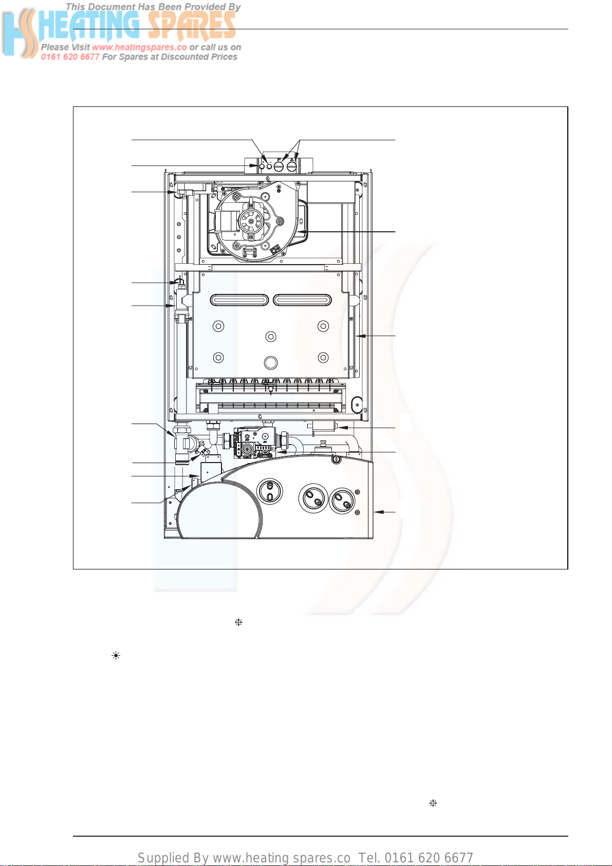
1.5 INTERNAL VIEW
KEY
1 Control panel
2 Ignition transformer
3 Combustion chamber
4Fan
5 Combustion analysis intakes
6 Negative pressure intake
7 Positive pressure intake
8 Air pressure switch
9 C.H. sensor (SM)
10 Main exchanger
11
100°C safety stat
12 Gas valve
13 Flow water switch
14 Diver tor valve
19 C.H. water filter
Fig. 3
1.6 BOILER OPERATION
The boiler operating mode is controlled by the selector switch
on the control panel. When set to winter ( ) it will operate in
the Domestic Hot Water and Central Heating modes. For
Domestic Hot Water only the selector switch should be set to
summer ( ).
Domestic hot water supply always takes priority over central
heating. If a demand for hot water is required during a central
heating period, the boiler will automatically switch to hot water
mode until the demand is satisfied.
1.6.1 Central Heating mode
If there is a call for central heating the pump will start to circulate the primary heating water and the fan will run at full speed;
once the air pressure switch has been proved the burner will
light. The burner output then automatically adjusts to suit the
system demand; as the temperature of the heating water in the
boiler approaches that set by the adjustable central heating
control knob the burner output is reduced. When this set temperature is reached, the burner extinguishes and the fan stops.
The pump continues to run for 30 seconds to prevent residual
heat build up in the boiler. The burner will not relight for 3 minutes unless there is a demand for domestic hot water during
this period.
1.6.2 Domestic hot water mode
When there is a demand for hot water, the diverter valve operates and the pump circulates the primary heating water. The
fan will run at full speed; once the air pressure switch has been
proved the burner will light.
The burner output then automatically adjusts to suit the
demand required to raise the temperature set by the
adjustable domestic hot water control knob. When the hot
water demand has been satisfied, the diverter valve operates
to divert the primary heating water to the central heating, if the
selector is set to winter ( ) and there is a C.H. demand, otherwise the burner will extinguish.

Supplied By www.heating spares.co Tel. 0161 620 6677
5
2.1 STATUTORY REQUIREMENTS
GAS SAFETY (INSTALLATION AND USE) REGULATIONS (as
amended). It is the law that all gas appliances are installed by
a registered person, in accordance with the above regulations. Failure to install appliances correctly could lead to prosecution. It is in your own interest, and that of safety, to ensure
that the law is complied with.
In addition to the above regulations, this appliance must be
installed in accordance with the current IEE Wiring
Regulations (BS 7671), Local Building Regulations, the
Building Standards (Scotland) (Consolidation) Regulations,
Byelaws of the local water undertaking, and Health and Safety
Document No 635 “The Electricity at Work Regulations
1989”. It should also be in accordance with the relevant recommendations in the current editions of the following British
Standards and Codes of Practice: BS5449, BS5546,
BS5440:1, BS5440:2, BS6798, BS6891, and BG.DM2,
BS7074, and BS5482 for propane installations.
Manufacturer’s instructions must NOT be taken in any way
as over-riding statutory obligations.
2.2 BOILER POSITION
In siting the combination boiler, the following limitations MUST
be observed:
– The boiler is not suitable for external installation. The posi-
tion selected for installation should be within the building,
unless otherwise protected by a suitable enclosure, and
MUST allow adequate space for installation, servicing, and
operation of the appliance, and for air circulation around it
(section 2.4).
– This position MUST allow for a suitable flue termination to
be made. The combination boiler must be installed on a
flat vertical wall which is capable of supporting the weight
of the appliance, and any ancillary equipment.
– If the combination boiler is to be fitted in a timber framed
building it should be fitted in accordance with the Institute
of Gas Engineers document for Gas Installations In Timber
Frame Housing, Reference 16E/UP/7: 1998. If in doubt,
advice must be sought from the gas supplier.
– If the appliance is installed in a room containing a bath or
shower, any electrical switch or control utilising mains
electricity must be so situated that it cannot be touched
by a person using the bath or shower. Attention is drawn
to the requirements of the current I.E.E. Wiring Regulations (BS 7671), and in Scotland the electrical provisions
of the Building Regulations applicable in Scotland.
– A compartment used to enclose the appliance MUST be
designed and constructed specifically for this purpose. An
existing cupboard, or compartment, may be used provided it is modified accordingly.
– Where installation will be in an unusual location, special
procedures may be necessary. BS6798 gives detailed
guidance on this aspect.
2.3 FLUE TERMINAL POSITION
Detailed recommendations for flue installation are given in
BS5440:1. The following notes are for general guidance:
– The boiler MUST be installed so that the terminal is
exposed to the external air.
– It is important that the position of the terminal allows free
passage of air across it at all times.
– It is ESSENTIAL TO ENSURE, in practice that products of
combustion discharging from the terminal cannot reenter the building, or any other adjacent building, through
ventilators, windows, doors, other sources of natural air
infiltration, or forced ventilation/air conditioning. If this
does occur, the appliance MUST be turned OFF IMMEDIATELY and the gas supplier consulted.
–
The minimum acceptable dimensions from the terminal to
obstructions and ventilation openings are specified in fig. 4.
– If the terminal discharges into a pathway or passageway
check that combustion products will not cause nuisance
and that the terminal will not obstruct the passageway.
– Where the lowest part of the terminal is fitted less than 2
m (78 in) above ground, above a balcony or above a flat
roof to which people have access, the terminal MUST be
protected by a purpose designed guard.
– Where the terminal is fitted within 850 mm (34 in) of a
plastic or painted gutter, or 450 mm (18 in) of painted
eaves, an aluminium shield at least 1,500 mm (59 in) long
must be fitted to the underside of the painted surface.
– The air inlet/outlet flue duct MUST NOT be closer than
25 mm (1 in) to combustible material.
– In certain weather conditions the terminal may emit a
plume of steam. This is normal but positions where this
would cause a nuisance should be avoided.
2 GENERAL REQUIREMENTS FOR INSTALLATION
Fig. 4
TABLE 5
Terminal position Minimum spacing in mm
A Directly below an openable window, 300
air vent or any other ventilation opening
B Below guttering, drain pipes or soil pipes 25*
C/D Below eaves, balconies or carport roof 25*
E From vertical drain pipes or soil pipes 75
F From internal or external corners 25
G Above adjacent ground, 300
roof or balcony level
H From a surface facing the terminal 600
I From a terminal facing the terminal 1,200
J From an opening in the carport 1,200
(e.g. door, window into dwelling)
K
Vertically from a terminal on the same wall
1,500
L
Horizontally from a terminal on the same wall
300
M
Horizontally from a vertical terminal to a wall
300
N Horizontally from an openable 300
window or other opening
P Above an openable window or other opening 300
* With “heat shield” installed in accordance to BS 5440 Pt1.
Supplied By www.heating spares.co Tel. 0161 620 6677
6
2.4 VENTILATION REQUIREMENTS
Detailled recommendations for air supply are given in
BS5440:2. The following notes are for general guidance:
–
It is not necessary to have a purpose provided air vent in the
room or compartment in which the appliance is installed.
2.5 GAS SUPPLY
– The gas installation should be in accordance with
BS6891. The gas required for the boiler is specified in
Table 4
.
– Ensure that the pipework from the meter to the appliance
is of adequate size.
–
The governor at the meter must give a constant outlet
pressure of 20 mbar (8 inwg) for natural gas and 30 - 37
mbar (12 - 15 inwg) for LPG, when the appliance is running.
– The gas supply line should be purged.
NOTE: Before purging open all doors and windows, also
extinguish any cigarettes, pipes, and any other naked
flames.
–
The complete installation must be tested for gas soundness.
2.6 ELECTRICITY SUPPLY
The appliance MUST be earthed. A mains supply of 230 V 50 Hz single phase is required. All external controls and
wiring MUST be suitable for mains voltage.
Wiring should be in 3 core PVC insulated cable NOT LESS
than 0.75 mm
2
(24 x 0.2 mm) to BS6500, Table 16. Wiring
external to the boiler MUST be in accordance with current
l.E.E. Wiring Regulations (BS 7671) and local regulations. The
supply connection to the flying lead provided MUST be made
to a fused double pole switch, having a 3 mm (1/8 in) contact
separation in both poles, serving only the boiler and system
controls; the fuse rating should be 3 amp. This connection
should be readily accessible and be made adjacent to the boiler (except in the case of bathroom installations for domestic
boilers where the point of connection to the mains MUST be
outside of the bathroom).
2.7 EXTERNAL CONTROLS (Refer to section 3.9)
The boiler is intended for use with a 24 V room thermostat.
The connection is made inside the control box as described in
section 3.9.
2.8 WATER SYSTEMS - GENERAL
– This appliance is designed for connection to sealed cen-
tral heating water systems.
– Check that the mains water pressure is suf ficient to pro-
duce the required D.H.W. flow rate, but does not exceed
the maximum D.H.W. pressure (
Table 4
). Where mains
pressure exceed 6 bar a pressure reducing valve must
be fitted in the D.H.W. inlet.
2.8.1 Treatment of Water Circulating Systems
– All recirculatory systems will be subject to corrosion
unless an appropriate water treatment is applied. This
means that the efficiency of the system will deteriorate as
corrosion sludge accumulates within the system, risking
damage to pump and valves, boiler noise and circulation
problems.
– For optimum performance after installation this boiler
and its associated central heating system must be
flushed in accordance with the guidelines given in BS
7593 “Treatment of water in domestic hot water central
heating systems”.
– This must involve the use of a proprietary cleanser, such
as BetzDearborn Sentinel X300 or X400, or Fernox
Superfloc. Full instructions are supplied with the products,
but for immediate information please contact BetzDearborn (0151 420 9563) or Fernox (01799 550 811)
directly.
– For long term protection against corrosion and scale,
after flushing it is recommended that an inhibitor such as
BetzDearborn Sentinel X100, or Fernox MB-1 or Copal is
dosed in accordance with the guidelines given in BS
7593.
Failure to flush and add inhibitor to the system may
invalidate the appliance warranty.
– It is important to check the inhibitor concentration after
installation, system modification and at every service in
accordance with the manufacturer’s instructions. (Test
kits are available from inhibitor stockists).
2.9 REQUIREMENTS FOR SEALED WATER SYSTEMS
The heating system design should be based on the following
information:
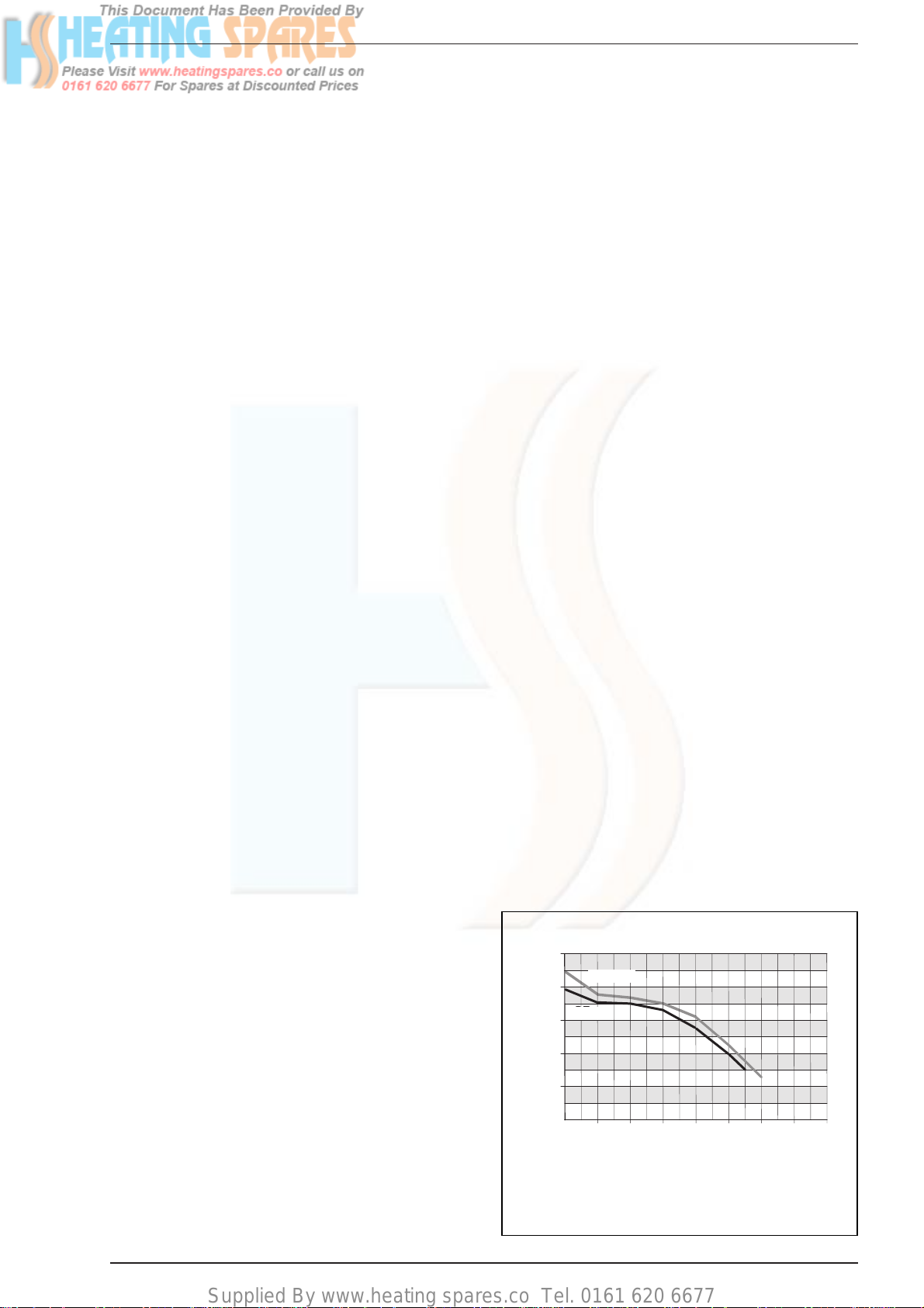
a) The available pump head is given in fig. 5.
b) The burner star ts when the C.H. flow reaches 400÷450
l/h. This safety condition is ensured by the flow switch.
c) The appliance is equipped with an internal by-pass that
operates with system heads (H) greater than 3 m. The
maximum flow through the by-pass is about 300 l/h. If
thermostatic radiator valves are to be installed, at least
one radiator should be without a thermostatic valve (usually the bathroom radiator).
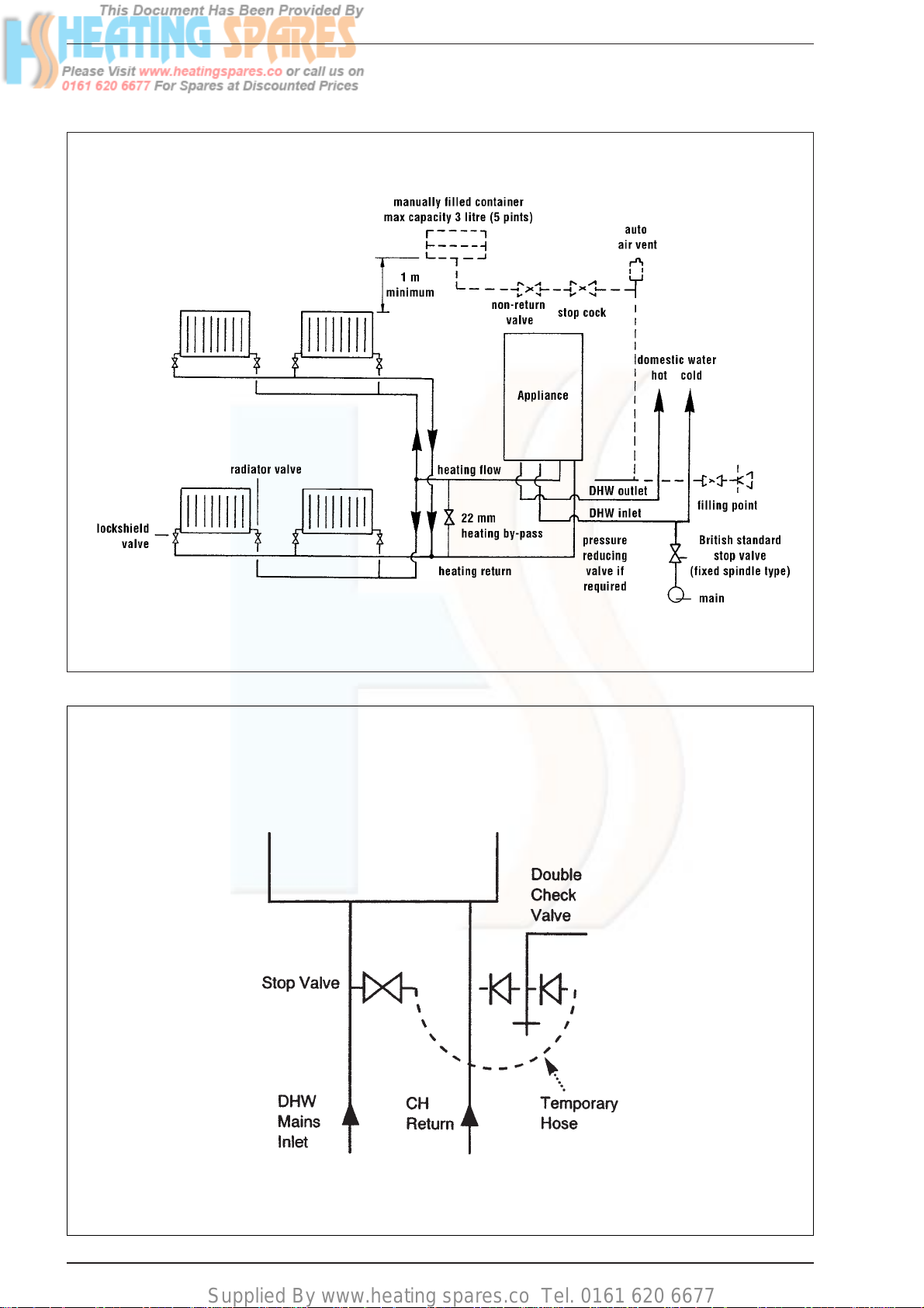
d) A sealed system must only be filled by a competent per-
son using one of the approved methods shown in fig. 7.
0
200
1600
140012001000800600400
PORTATA (l/h)
PREVALENZA RESIDUA (mbar)
500
400
10 0
200
300
30 - 35
25
Format.zip
KEY
1 Available Head for “80 C - 100 C” models
2 Available Head for “110 C” model
Flow rate (l/sec)
Available head (mbar)
Fig. 5
1
2
Supplied By www.heating spares.co Tel. 0161 620 6677
7
TYPICAL SYSTEM DESIGN
ALTERNATIVE METHODS OF FILLING A SEALED SYSTEM
NOTE: A drain cock should be installed at the lowest point of the heating circuit and beneath the appliance.
Fig. 6
Fig. 7
 Loading...