


INSTALLER INSTRUCTIONS
CONTENTS
1 DESCRIPTION OF THE BOILER . . . . . . . . . . . . . . . . . . . . . . . . . . . . . . . . . . . . . . . . . . . . . . . . . . . . . . . . . . . . . . . . pag. 94
2 INSTALLATION . . . . . . . . . . . . . . . . . . . . . . . . . . . . . . . . . . . . . . . . . . . . . . . . . . . . . . . . . . . . . . . . . . . . . . . . . . . . . . pag. 98
3 CHARACTERISTICS . . . . . . . . . . . . . . . . . . . . . . . . . . . . . . . . . . . . . . . . . . . . . . . . . . . . . . . . . . . . . . . . . . . . . . . . . . pag. 108
4 USE AND MAINTENANCE . . . . . . . . . . . . . . . . . . . . . . . . . . . . . . . . . . . . . . . . . . . . . . . . . . . . . . . . . . . . . . . . . . . . pag. 111
IMPORTANT
When carrying out commissioning of the boiler, you are highly recommended to perform the following checks:
–
Make sure that there are no liquids or inflammable materials in the immediate vicinity of the boiler.
– Make sure that the electrical connections have been made correctly and that the earth wire is connected to a
good earthing system.
– Open the gas tap and check the soundness of the connections, including that of the burner.
– Make sure that the boiler is set for operation for the type of gas supplied.
– Check that the flue pipe for the outlet of the products of the combustion is unobstructed and has been properly
installed.
– Make sure that any shutoff valves are open.
– Make sure that the system is charged with water and is thoroughly vented.
– Check that the circulating pump is not locked (CAUTION: Remember to release the pump coupled with the control
panel, if necessary, to protect the electronic control card).
– Purge the system, bleeding off the air present in the gas pipe by operating the pressure relief valve on the gas
valve inlet.
– Check that the syphened drip is fully filled with water. If necessary, fill it via the special opening.
FONDERIE SIME S.p.A. of Via Garbo 27 - Legnago (VR) - Italy declares that its hot water boilers, which bear the CE
mark under Gas Directive 90/396/CEE and are fitted with a safety thermostat calibrated to a maximum of 110°C,
are not subject to application of PED Directive 97/23/CEE as they meet the requirements of article 1 paragraph
3.6 of the Directive.
DEWY - ENGLISH

IT
ES
PT
GB
94
1.1 INTRODUCTION
“DEWY” boilers are premix condensation
thermal appliances which use microprocessor technology for function control and
management. They comply with the european directives 90/396/CEE,
89/336/CEE, 73/23/CEE, 92/42/CEE
and with the european specifications EN
483 - EN 625.
These appliances can be fired by natural
gas (methane) and propane gas (G31).
The instructions given in this manual are
provided to ensure proper installation and
perfect operation of the appliance.
1 DESCRIPTION OF THE BOILER
1.2 DIMENSIONS
1.2.1 “30/80” model
330
G
240
310
M
R
55
S2
C
U
S1
E
70
490
390
13 0
S3
230
230
74 5
Ø 60/100
230
65
1290
460
215
Fig. 1
CONNECTIONS
R C.H. return 3/4” (UNI-ISO 228/1)
M C.H. flow 3/4” (UNI-ISO 228/1)
G Gas connection 3/4” (UNI-ISO 228/1)
E D.H.W. inlet 3/4” (UNI-ISO 228/1)
U D.H.W. outlet 3/4” (UNI-ISO 228/1)
C Recirculation 3/4” (UNI-ISO 228/1)
S1 C.H. safety relief valve
S2 Tank unit safety relief valve
S3 Condensation outlet ø 25
600
65
1620
610
315
252
76
M2
R2
M1
R1
M
R
S1
C1
S3
G
S2
117
62
U
C
E
10 9
349
712
946
70
110 9
1229
70
1349 140
300
300
828
846
1.2.2 “30/130” model
CONNECTIONS
R Zone 1 system return 3/4” (UNI-ISO 228/1)
R1 Zone 2 system return (optional) 3/4” (UNI-ISO 228/1)
R2 Zone 3 system return / Low
temperature return (optional) 3/4” (UNI-ISO 228/1)
M2 Zone 3 system delivery / Low
temperature delivery (optional) 3/4” (UNI-ISO 228/1)
M1 Zone 2 system delivery (optional) 3/4” (UNI-ISO 228/1)
M Zone 1 system delivery 3/4” (UNI-ISO 228/1)
G Gas connection 3/4” (UNI-ISO 228/1)
E D.H.W. inlet 3/4” (UNI-ISO 228/1)
U D.H.W. outlet 3/4” (UNI-ISO 228/1)
C Recirculation 3/4” (UNI-ISO 228/1)
C1 Recirculation pump kit (optional) 1/2” (UNI-ISO 228/1)
S1/S2 C.H. safety relief valve/tank
S3 Condensation outlet ø 25
Fig. 1/a

IT
ES
PT
GB
95
1.3 TECHNICAL FEATURES
DEWY 30/80 DEWY 30/130
Heat output
Nominal (80-60°C) kW (kcal/h) 29,3 (25.200) 29,3 (25.200)
Minimum (80-60°C) kW (kcal/h) 10,4 (9.000) 10,4 (9.000)
Nominal (50-30°C) kW (kcal/h) 32,0 (27.600) 32,0 (27.600)
Minimum (50-30°C) kW (kcal/h) 11,4 (9.800) 11,4 (9.800)
Nominal D.H.W. heat output kW 29,3 29,3
Heat input
Nominal/Minimum kW 30,0 / 10,8 30,0 / 10,8
Efficiency (80-60°C)
Nominal/Minimum output % 97,7 / 96,7 97,7 / 96,7
Efficiency (50-30°C)
Nominal/Minimum output % 106,8 / 105,8 106,8 / 105,8
Water content l 9,5 10,9
Adsorbed power consumption W175 175
Electrical protection grade
IP X4D IP X4D
Maximum water head bar 3 3
Maximum temperature °C 85 85
Expansion vessel
Capacity l 8 10
Preloading pressure bar 1 1
C.H. setting range °C 20 - 80 20 - 80
D.H.W. setting range °C 10 - 60 10 - 60
D.H.W. production
D.H.W. flow rate (EN 625) l/min 19,9 21,0
Continuous D.H.W. flow rate ∆t 30°C l/min 14 14
Maximum D.H.W. pressure bar 7 7
D.H.W. tank capacity l 80 130
D.H.W. expansion vessel l 4 4
Recuperation time between 25 and 55°C min 9’ 9’40”
Smokes temperature
Maximum/ Minimum (80-60°C) °C 70 / 69 70 / 69
Maximum/ Minimum (50-30°C) °C 48 / 45 48 / 45
Smokes flow kg/h 49 49
Category II
2H3P II2H3P
Type B23, C13-33-43-53 B23, C13-33-43-53
Weight kg 127 191
Main burner nozzles
Quantity n° 1 1
G20 ø mm 6,0 6,0
G25 ø mm 7,7 7,7
G31 ø mm 4,3 4,3
Gas consumption
Nominal / Minimum (G20) m
3
st/h 3,17 / 1,14 3,17 / 1,14
Nominal / Minimum (G25) m
3
st/h 3,69 / 1,32 3,69 / 1,32
Nominal / Minimum (G31) kg/h 1,22 / 0,44 1,22 / 0,44
Gas supply pressure
G20 mbar 20 20
G25 mbar 25 25
G31 (Propan) mbar 37 37
CO
2 % methane (G20) min/max 9,2 / 9,3 9,2 / 9,3
CO
2 % methane (G25) min/max 9,5 / 9,6 9,5 / 9,6
CO
2 % propan (G31) min/max 10,1 / 10,3 10,1 / 10,3
CO emission ppm 27 27
NOx emission (Class 5) ppm 35 35
(1)
Flow calculated with a fixed temperature on the hot-water service potentiometer of 60° C for a maximum period of 10 minutes
IT
ES
PT
GB
96
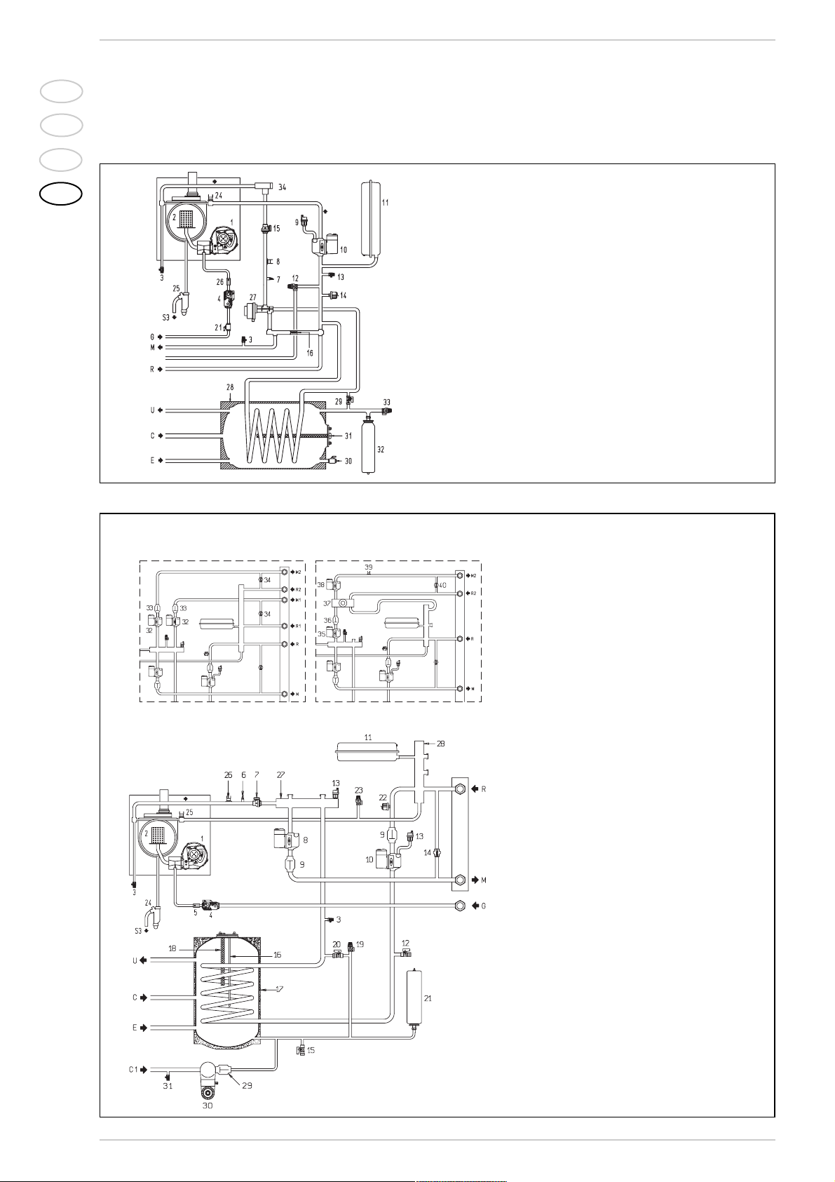
1.4 FUNCTIONAL DIAGRAM
1.4.1 “30/80” model
Fig. 2
KEY
1Fan
2 Water-gas exchanger
3 Breather valve
4 Gas valve
7 C.H. sensor (SM)
8 100°C safety stat
9 Air relief valve
10 Circulation pump
11 Expansion vessel
12 Safety valve
13 Boiler discharge
14 Water pressure transducer
15 Flowmeter
16 Automatic by-pass
21 Gas cock
24 Limit stat
25 Condensation water trap
26 Gas rate adjuster
27 Motor-operated diverter valve
28 Storage tank 80 liter
29 Filling cock
30 D.H.W. discharge cock
31 Magnesium anode
32 D.H.W. expansion vessel
33 D.H.W. safety valve 7 bar
34 Aqua Guard Filter System
CONFIGURAZIONE
KIT BASSA TEMPERATURA
CONFIGURAZIONE
KIT POMPA 2/3 ZONA
1.4.2 “30/130” model
Fig. 2/a
KEY
1Fan
2 Water-gas exchanger
3 Breather valve
4 Gas valve
5 Gas rate adjuster
6 C.H. sensor (SM)
7 Flowmeter
8 Zone 1 system pump
9 Single-acting valve
10 Hot water tank pump
11 Expansion vessel
12 Boiler discharge
13 Air relief valve
14 Automatic by-pass
15 D.H.W. discharge cock
16 Tap water probe (SB)
17 Storage tank 130 liter
18 Magnesium anode
19 D.H.W. safety valve 7 bar
20 Filling cock
21 D.H.W. expansion vessel
22 Water pressure transducer
23 Safety valve
24 Condensation water trap
25 Limit stat 85°C
26 100°C safety st at
27 System delivery manifold
28 System return manifold
RECIRCULATION KIT CONFIGURATION (code 8102600)
29 Single-acting valve
30 Recirculation pump with programmer timer
31 Pressure relief valve
PUMP KIT 2/3 ZONE CONFIGURATION
(code 8100700/8100710)
32 Zone 2 and 3 system pump
33 Zone 2 and 3 single-acting valve
34 Zone 2 and 3 system bypass
LOW TEMPERATURE KIT CONFIGURATION
(code 8100760)
35 Mixer valve delivery pump
36 Unidirectional low temperature valve
37 Mixer valve
38 Low temperature delivery pump
39 Low temperature safety thermostat
40 Low temperature bypass
PUMP KIT 2/3 ZONE
CONFIGURATION
LOW TEMPERATURE KIT
CONFIGURATION
IT
ES
PT
GB
97
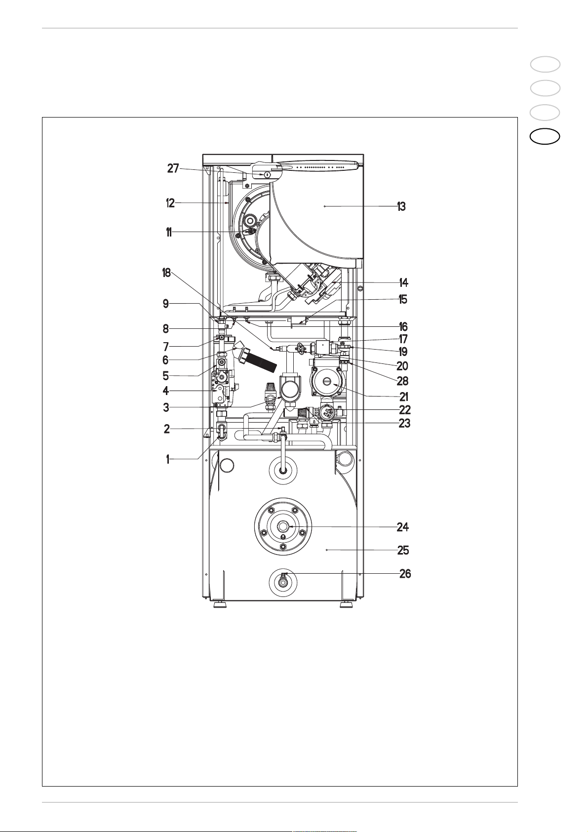
1.5 MAIN COMPONENTS
1.5.1 “30/80” model
Fig. 3
KEY
1 Gas cock
2 Manual filling
3 Motor -operated diverter valve
4 Gas valve
5 Gas rate adjuster
6 Condensation water trap
7 Gas pressure take-off
8 Positive pressure take-off
9 Breather valve
11 Sensing electrode
12 Water-gas exchanger
13 Control panel
14 F an
15 Ignition transformer
16 Negative pressure take-off
17 Flowmeter
18 C.H. sensor (SM)
19 Automatic breather
20 100°C safety stat
21 Circulating pump
22 Water pressure transducer
23 Safety valve
24 Magnesium anode
25 Storage tank 80 liter
26 D.H.W. discharge cock
27 Smoke stat
28 Aqua Guard Filter System
IT
ES
PT
GB
98
38
37
39
40
41
8
10
CONFIGURAZIONE
KIT BASSA TEMPERATURA
CONFIGURAZIONE
KIT POMPA 2/3 ZONA
35
36
34
33
8
10
19
20
21
22
24
23
25
26
27
28
29
30
31
18
32
1
2
3
4
5
6
7
8
9
10
11
12
13
14
15
16
17
42
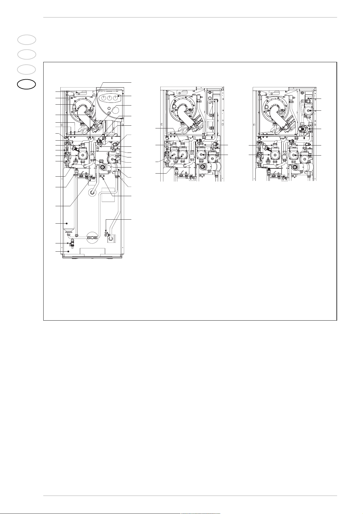
1.5.2 “30/130” model
Fig. 3/a
The boiler must be installed in a fixed location and only by specialized and qualified
firms in compliance with all instructions
contained in this manual. Furthermore, the
installation must be in accordance with current standards and regulations.
2.1 BOILER ROOM
The
“DEWY”
version boilers can be installed in any domestic environment without
any location restrictions or comburent air
requirements.
2.2 CONNECTING UP SYSTEM
To protect the heat system from damaging
corrosion, incrustation or deposits, af ter
installation it is extremely important to
clean the system using suitable products
such as, for example, Sentinel X300 or
X400. Complete instructions are provided
with the products but, for further information, you may directly contact GE Betz.
For long-term protection agains corrosion
and deposits, the use of inhibitors such as
Sentinel X100 is recommended after cleaning the system. It is important to check
the concentration of the inhibitor after
each system modification and during maintenance following the manufacturer’s
instructions (specific tests are available at
your dealer). The safety valve drain must be
connected to a collection funnel to collect
any discharge during interventions.
WARNING: Failure to clean the heat
system or add an adequate inhibitor invalidates the device’s warranty.
Gas connections must be made in accordance with current standards and regula-
tions. When dimensioning gas pipes from
the meter to the module, both capacity
volume (consumption) in m3/h and gas
density must be taken into account.
The sections of the piping making up the
system must be such as to guarantee a
supply of gas sufficient to cover the maximum demand, limiting pressure loss
between the gas meter and any apparatus
being used to not greater than:
– 1.0 mbar for family II gases (natural gas);
– 2.0 mbar for family III gases (butane or
propane).
A sticker inside the module includes identification and gas type data specific to the
module.
2.2.1 Connection of condensation
water trap
The drip board and its water trap must be
2 INSTALLATION
LEGEND
1 130 litre hot water tank
2 Hot water tank drain cock
3 Hot water tank expansion tank
4 Manual filling unit
5 Hot water tank safety valve
6 Automatic bleed
7 Gas valve
8 Zone 1 heating system pump
9 Gas flow control
10 Zone 1 single-acting valve
11 Condensation drain trap
12 Manual pressure relief valve
13 Positive pressure intake
14 Negative pressure intake
15 Ignition transformer
16 Measurement electrode
17 Primary exchanger
18 Ignition electrode
19 Control panel
20 Ventilator
21 Heating probe (SM)
22 100°C safety thermometer
23 Heating system safety valve
24 Water pressure transducer
25 Single-acting valve
26 Manual recirculation kit bleed (optional)
27 Hot water tank pump
28 Flow switch
29 Tap water recirculation pump with timer
(optional)
30 Single-acting valve (optional)
31 Manual pressure relief valve
32 Boiler drain cock
33 Zone 2 heat pump (optional)
34 Zone 2 single-acting valve (optional)
35 Zone 3 single-acting valve (optional)
36 Zone 3 heat pump (optional)
37 Low temperature safety thermostat
(optional)
38 Low temperature delivery pump (optional)
39 Mixer valve (optional)
40 Low temperature single-acting valve
(optional)
41 Mixer valve delivery pump (optional)
42 Smoke stat
PUMP KIT 2/3 ZONE
CONFIGURATION
LOW TEMPERATURE KIT CONFIGURATION

IT
ES
PT
GB
99
connected to a civil drain through a pipe
with a slope of at least 5 mm per metre to
ensure drainage of condensation water.
The plastic pipes normally used for civil
drains are the only type of pipe which is
appropriate for conveying condensation
to the building’s sewer pipes.
2.2.2 Filter on the gas pipe
The gas valve is supplied ex factory with an
inlet filter, which, however, is not adequate to
entrap all the impurities in the gas or in gas
main pipes.
To prevent malfunctioning of the valve, or in
certain cases even to cut out the safety device with which the valve is equipped, install an
adequate filter on the gas pipe.
2.4 SYSTEM FILLING
Filling of the boiler and the system is done
by the charge cock
(2 fig. 3 - 4 fig. 3/a).
The charge pressure, with the system
cold, must be 1 bar.
Filling must be done slowly so as to allow
any air bubbles to be bled off through the
air valves.
Once the filling has been completed, close
the filling tap.
2.5 COAXIAL DUCT ø 60/100
The air inlet-smoke outlet assembly, code
8096250, is included in the standard supply of the appliance complete with mounting
instructions.
2.5.1 Coaxial duct
accessories
The accessories to be used for this type of
installation and some of the connecting
systems that may be adopted are illustred
in fig. 4.
With the pipe bend included in the kit, the
maximum length of the piping should not
exceed 2.8 meter.
When the vertical extension code
8086950 is used, the terminal par t of the
pipe must always come out horizontally.
2.5.2 Positioning the
outlet terminals
The outlet terminals for forced-draught
appliances may be located in the external
perimeter walls of the building.
To provide some indications of possible solutions, Table 1 gives the minimum distances
to be observed, with reference to the type
of building shown in fig. 5.
Fig. 5
TABLE 1
Siting of terminal Appliances from 7 to 35 kW
(distances in mm)
A - below openable window 600
B - below ventilation opening 600
C - below eaves 300
D - below balcony (1) 300
E - from adjacent window 400
F - from adjacent ventilation opening 600
G - from horizontal or vertical soil or drain pipes (2) 300
H - from corner of building 300
I - from recess in building 300
L - from ground level or other treadable surface 2500
M - between two terminals set ver tically 1500
N - between two terminals set horizontally 1000
O - from a surface facing without openings or terminals 2000
P - as above but with openings and terminals 3000
1)
Terminals below a practicable balcony must be located in such a way that the total path of the smoke
from its outlet point from the terminal to its outlet point from the external perimeter of the balcony, including the height of possible railings, is not less than 2000 mm.
2) When siting terminals, where materials that may be subject to the action of the combustion products
are present in the vicinity, e.g., eaves, gutters and downspouts painted or made of plastic material,
projecting timberwork, etc., distances of not less than 1500 mm must be adopted, unless adequate
shielding is provided to guard these materials.
IMPORTANT:
Each additional 90° curve installed reduces
the available length by 0.90 metres.
Each additional 45° curve installed reduces
the available length by 0.45 metres.
Fig. 4
KEY
1a-b Coaxial duct kit code 8096250
2a Extension L. 1000 code 8096150
2b Extension L. 500 code 8096151
3 Vertical extension L. 140 with take-off point code 8086950
4a 90° additional bend code 8095850
4b 45° additional bend code 8095950
NOTE
Before connecting
accessories, it is
always advisable to
lubricate the internal
part of the gaskets
with silicon products.
Avoid using oils and
greases.

IT
ES
PT
GB
2.5.3 Coaxial duct outlet on the roof
The accessories to be used for this type of
installation and some of the connecting
systems that may be adopted are illustrated in fig. 7.
It is possible to insert up to a maximum of
three extensions and reach a maximum
rectilinear distance of 3.7 meter.
Should it be necessary to make two changes of direction in the pipe development,
the maximum length of the pipe must not
exceed 2 meter.
2.6 SEPARATE PIPES ø 80
A special kit may be used to separate the
flue gas outlet from the fresh air intake.
The intake may be installed to the right or
left of the flue gas outlet.
Both ducts may be oriented in any direction.
Refer to fig. 8 for positioning.
The maximum overall length of the intake
and exhaust ducts depends on the head
losses of the single fittings installed
(excluding the doublers) and must not be
greater than 15,5 mm H2O.
For head losses in the fittings, refer to
Table 2.
2.6.1 Separate pipe accessories
Kit code 8089911 is supplied for this purpose (fig. 9).
The sectored diaphragm is to be used
according to the maximum head loss
allowed in both pipes, as given in fig. 10.
KEY
1 Blind flange
2 Flue gas duct flange
3 Fixing screw
4 Gasket ø 125/95
5 Intake duct collar
Fig. 9
100
Fig. 7
15 5
Ø 80
Ø 80
10 5
P
L
CA
K
Z
CS
KEY
CA Inlet
CS Outlet
Example of allowable installation calculation in that the sum of the head losses of the
single fittings is less than 15,5 mm H2O:
Inlet Outlet
7 m horizontal pipe ø 80 x 0,20 1,40 –
7 m horizontal pipe ø 80 x 0,40 – 2,80
n° 2 90° elbows ø 80 x 0,30 0,60 –
n° 2 90° elbows ø 80 x 0,50 – 1,00
n° 1 terminal ø 80 0,10 0,40
Total head loss 2,10 + 4,20 = 6,3 mm H2O
TABLE 2
Accessories ø 80 Total head loss (mm H2O)
DEWY
Inlet Outlet Roof outlet
90° elbow MF 0,30 0,50 –
45° elbow MF 0,20 0,40 –
Extension L. 1000 (horizontal) 0,20 0,40 –
Extension L. 1000 (vertical)) 0,30 0,30 –
Outlet terminal – 0,40 –
Inlet terminal 0,10 – –
Doubler fitting 0,30 – –
Roof outlet terminal L.1381 – – 0,60
Fig. 8
30/80 30/130
Kmm 215 348
L mm 130 263
P mm 245 230
Z mm 330 315
KEY
1 Vertical extension L. 140 with take-off points code 8086950
2a Extension L. 1000 code 8096150
2b Extension L. 500 code 8096151
3 Tile with ar ticulation joint code 8091300
4 Roof outlet terminal L. 1285 code 8091205
5 Supplementary 90° elbow code 8095850
6 Supplementary 45° elbow code 8095950
NOTE
Before connecting accessories, it is
always advisable to lubricate the
internal part of the gaskets with
silicon products. Avoid using oils
and greases.
3
4
2
5 3
1

IT
ES
PT
GB
101
2.6.2 Connection with existing flues
The ø 80 flue gas pipe may be connected to
an existing flue. When the “DEWY” boiler is
running at a low temperature, a regular flue
may be used under the following conditions:
– No other boiler must be using the flue.
–
The flue interior must be shielded
from direct contact with condensation
from the boiler.
The products of combustion must be
conveyed through a flexible or rigid plastic pipe around 100 to 150 mm in diameter, and condensation must be sipho-
ned off at the foot of the pipe.
The usable height of the water trap must
be at least 150 mm.
2.6.3 Separate-pipes roof outlet
The accessories to be used for this type of
installation and some of the connecting
systems that may be adopted are illustrated in fig. 12.
There is the possibility of doubling the airintake and smoke-outlet pipes and then bringing them back together again so as to
obtain a concentric discharge by using the
doubler fitting (9 fig. 12).
In these cases, when assembling, recover
the silicone gasket used on the terminal
adapter (5 fig. 11), which is to be replaced
by the doubler, and insert it into the seat
made in the doubler.
For this type of discharge the sum of the
maximum rectilinear development
allowed for the pipes must not exceed
15,5 mm H2O.
When calculating the lengths of pipe, take
into account the parameters given in the
Table 2.
Fig. 10
KEY
1 Separate pipes kit code 8089911
2 90° elbow MF code 8077450 (6 pz.)
3 90° elbow MF with take-off points code 8077452
4a Extension L. 1000 code 8077351 (6 pz.)
4b Extension L. 500 code 8077350 (6 pz.)
5 Outlet terminal code 8089501
6 Int.-est. ring kit code 8091500
7 Inlet terminal code 8089500
8 45° elbow MF code 8077451 (6 pz.)
NOTE
Before connecting accessories, it is always
advisable to lubricate the internal part of the
gaskets with silicon products. Avoid using oils
and greases.

2.8 ELECTRICAL CONNECTION
The boiler is supplied with an electric cable.
Should this require replacement, it must be
purchased exclusively from SIME. The electric power supply to the boiler must be
230V - 50Hz single-phase through a fused
main switch, with at least 3 mm spacing
between contacts. Respect the L and N
polarities and the earth connection.
NOTE: Device must be connected to an
efficient earthing system. SIME declines
all responsibility for injury or damage to
persons, animals or things, resulting from
the failure to provide for proper earthing
of the appliance. Always turn off the
power supply before doing any work on
the electrical panel.
2.8.1 Room stat connection
(fig. 13 pos. A)
To gain access to the electronic board connector (3), remove the control panel cover
and connect the room stat to the terminals
TA (5-6) after having removed the jumper.
The thermostat or timer-thermostat,
recommended for better room temperature control, must be class II as specified by
standard EN 60730.1 (clean contact).
WARNING: Applying mains voltage to the
terminals of conector (3) will irreparably
damage the control board. Make sure
that any connections to be made are not
carrying mains voltage.
2.8.2 “Logica Remote Control”
connection (fig. 13 pos. B)
The electrical plant must comply with local
standards and all cables must comply with
low safety voltage requirements of EN
60730. For lengths up to 25 m, use cables
of section 0.25 mm2, for longer lengths up
to 50 m use cables of section 0.5 mm2.
First of all, assemble and wire the socket
(2), then insert the equipment which will
start-up as soon as it receives current.
To gain access to connector (3) remove the
control panel cover and connect the climate
regulator to terminals CR (6-7).
WARNING: External voltage must not be
connected to terminals 1-2-3-4 of the
"Logica Remote Control". A telephone remote switch with a zero potential contact or a
window contact can be connected to terminals 3-4. Equipment for the checking of civil
plants via a telephone line includes the
model TEL 30.4 LANDIS & STAEFA.
2.8.3 External temperature sensor
connection (fig. 13 pos. C)
The cables must comply with low safety voltage requirements of EN 60730. For lengths
up to 25 m, use cables of section 0.25 mm2,
for longer lengths up to 50 m use cables of
section 0.5 mm2.
To gain access to boiler connector (3) remove the control panel cover and connect the
external temperature sensor to terminals
SE (8-9).
102
IT
ES
PT
GB
Fig. 12
KEY
1 Separate pipes kit code 8089911
2 90° elbow MF
code 8077450 (6 pz.)
3
90° elbow
MF with take-off points code 8077452
4 a Extension L. 1000 code 8077351 (6 pz.)
4 b Extension L. 500 code 8077350 (6 pz.)
6 Int.-est. ring kit code 8091500
7 Inlet terminal code 8089500
9 Doubler fitting code 8091400
10 Tile with articulated joint code 8091300
11
Roof outlet terminal L. 1381
code 8091204
NOTE
Before connecting accessories, it is always
advisable to lubricate the internal part of the
gaskets with silicon products. Avoid using oils
and greases.

IT
ES
PT
GB
103
TA
CR
CR
SE
2
A
B
C
3
1
SB
SB
SB
KEY
1 Control panel
2 “Logica Remote Control” socket
3 Conector (J2)
TA Room stat
(not supplied)
CR Logica Remote Control
(optional)
SE External temperature sensor
(optional)
SB D.H.W. sensor
KEY
EV1 Gas valve coil
EV2 Gas valve coil
EA Ignition electrode
ER Sensing electrode
TS 100°C safety stat
VFan
TPA Water pressure transducer
VD Motor-operated diverter valve
PI Pump
SE External sensor (optional)
TA Room stat
SM C.H. sensor (blue)
TL Limit stat
TRA Ignition transformer
TR Transformer 230 - 24V
FL Flowmeter
SS D.H.W. sensor (red)
CR Logica Remote Control (optional)
SV Ventilator board
OP Time programmer
TF Smoke stat
Note: The room stat must (TA) be connected to the terminals 5-6
CONNECTOR SPARE PART CODES:
J2 code 6278613
J3 code 6278660
J4 code 6278659
J5 code 6278658
J7 code 6278636
Fig. 14
2.8.4 Wiring diagram “30/80” model
Fig. 13

IT
ES
PT
GB
104
KEY
EV1 Gas valve coil
EV2 Gas valve coil
EA Ignition electrode
ER Sensing electrode
TS 100°C safety stat
VFan
TPA Water pressure transducer
PI Pump
SE External sensor (optional)
TA Room stat
SM C.H. sensor (blue)
TL Limit stat
TRA Ignition transformer
TR Transformer 230 - 24V
FL Flowmeter
SS D.H.W. sensor (red)
CR Logica Remote Control (optional)
SV Ventilator board
OP Time programmer
TF Smoke stat
PB Hot water tank pump
PR Recirculation pump (optional)
Note: The room stat must (TA) be connected to the terminals 5-6
CONNECTOR SPARE PART CODES:
J2 code 6278613
J3 code 6278660
J4 code 6278659
J5 code 6278658
J7 code 6278636
Fig. 14/a
2.8.5 Wiring diagram “30/130” model
Fig. 14/b
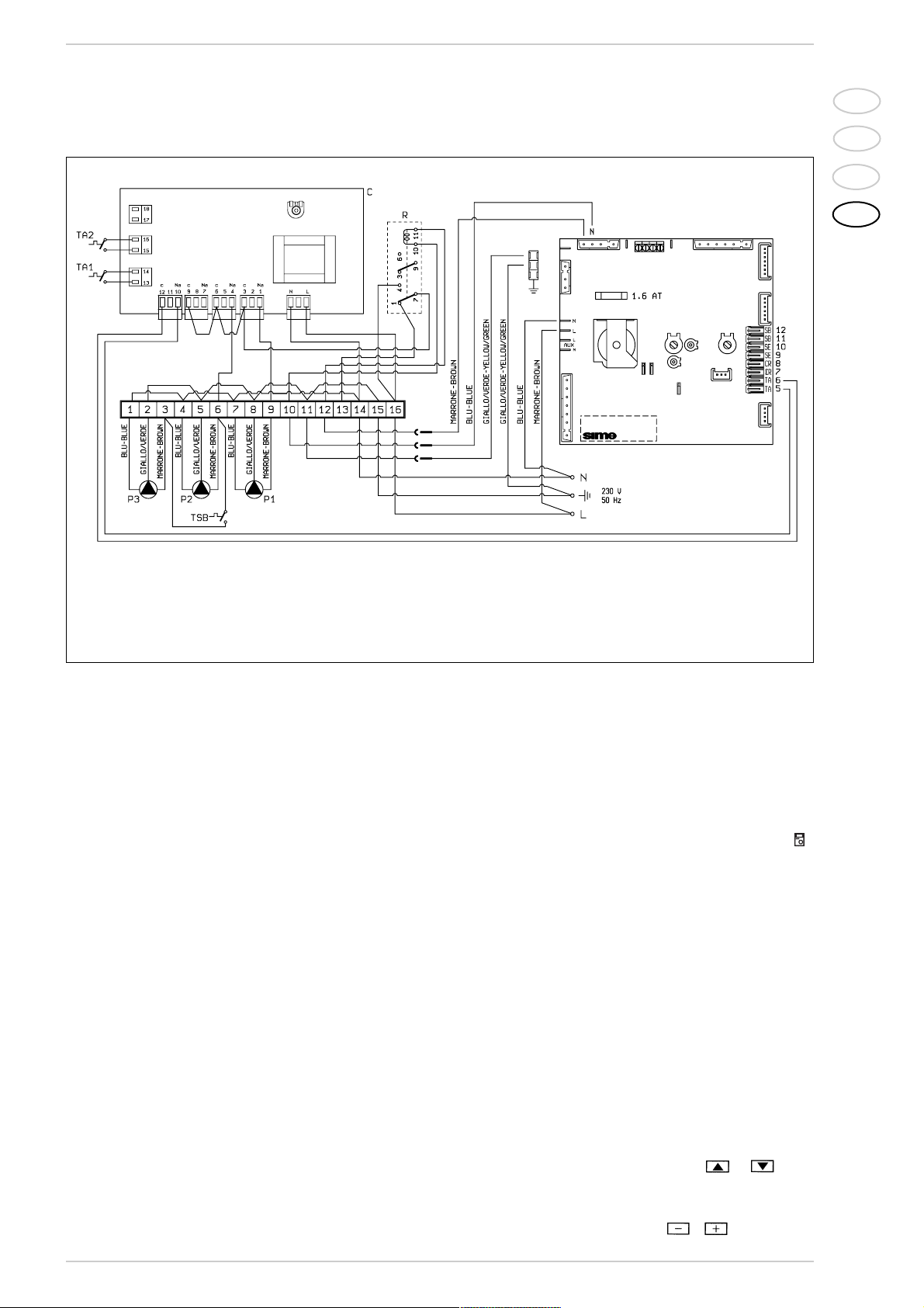
2.8.6 “30/130” wiring diagram with zone pump kit (code 8100700) and third zone pump kit (8100710)
LEGEND
C Zone control unit
R Relay
P1 Zone 1 system pump
P2 Zone 2 system pump
P3 Zone 3 system pump
TA1 Zone 1 room thermostat
TA2 Zone 2 room thermostat
TA3 Zone 3 room thermostat
IT
ES
PT
GB
105
2.9 LOGICA REMOTE CONTROL
All the boiler's functions can be managed
by a optional digital multifunctional device
code 8092204 for the remote of the boiler itself and for regulating room climatic
conditions with an operational reserve of
12 hours.
The heating circuit is controlled by the room
temperature sensor built-in the equipment
or by the atmospheric conditions, with or
without environmental inflow, if the boiler is
connected to an external sensor.
Characteristics:
– Ergonomic control unit divided according
to function (control levels)).
– Clear division of basic functions:
• operating regime, correction of set
value and presence button are directly
accessible;
• Different real current values are
accessible through the "info" button;
• other functions can be programmed
after the cover has been opened;
• special service level with protected
access;
– Each setting or modification is displayed
and confirmed.
– Tome setting (special line for changing
BST/CET).
– Heating programme with max. 3 heating
periods per day, individually selectable.
–
Copy function for easy transfer of heating programme to the next or pre-
vious day.
–
Holiday programme: the programme is
interrupted for the holiday period and automatically restar ted on returning home.
– Option to return the heating program to
default values.
– Programming lock (child safety).
Functions:
– Delivery temperature control guided by
the atmospheric conditions, taking into
account the dynamics of the building.
– Delivery temperature control guided by
atmospheric conditions with influence of
ambient temperature.
– Ambient temperature control only.
– Adjustable influence of ambient tempera-
ture shift .
– Switch-on and switch-off optimisation.
– Rapid lowering.
– ECO functions (daily heating limiter, auto-
matic summer/winter switch-over).
– Controllable maximum delivery tempera-
ture limit (specifically for floor plants).
– Limitation of increase in pre-set delivery
temperature.
– Anti-freeze protection for buildings.
– Hourly programming of the tank unit
temperature on two levels: comfort and
reduced.
– Domestic hot water control with nominal
value requirement and enable.
– Connection to room sensor or switching
of operating regime through the telepho-
ne system with external contact or
through a window contact.
– Anti-bacterial.
2.9.1 Installation
The unit must be installed in the main living
room. For installation, follow the assembly
instructions inserted in the package.
At this point, with the selector knob on ( ),
the installer can adjust the basic parameters settings according to the individual
needs (point 2.8.2).
If there is a thermostatic radiator valve
fitted, this must be set to maximum.
2.9.2 Installation settings
The settings for the basic operating parameters for individual needs are reported in
the instruction leaflet supplied with the
"Logica Remote Control" and in the section
reserved for the user in this manual.
For further adjustments which can be carried out by the installer, the "Logica Remote
Control" offers a level of service and parameterising which can only be accessed
through a special combination of buttons.
To activate this level of service or parameterising press buttons and least 5
seconds. This will activate the parameterising level. Then use the same arrow buttons
to select the individual input lines and adjust
the values with or .
Fig. 14/c
2.8.7 “30/130” wiring diagram with low temperature kit code 8100760
LEGEND
C Zone control unit
R Relay
P1 Zone 1 system pump
P2-P3 Low temperature zone pump
TA1 Zone 1 room thermostat
TA2 Low temperature zone room thermostat
TAB Low temperature safety thermostat

IT
ES
PT
GB
106
Maximum limit of delivery
temperature
Variation of the maximum speed of the
delivery temperature
Activation of adaptation
Optimisation of
switch-on time
Heating gradient
Presetting switch-off
time (00 = off)
The delivery temperature is limited to the maximum set value.
The increase per minute of the prescribed delivery temperature value sent
in °C is limited to the imposed value.
With the activation of the adaptation, the pre-set value transmitted to the
boiler regulator is adapted to the effective heat need.
The adaptation functions with both the atmospheric guide with ambient
influence and with pure ambient control.
If the "Logica Remote Control" is set as a remote control only, the adaptation
must be is deactivated.
If the switch-on time optimisation is active, the "Logica Remote Control" modifies the heating gradient until it finds the optimum heating point
0 = off 1 = on
The "Logica Remote Control" selects the switch-on time such that the set
value has more or less been reached at the start of the usage time.
The more severe the night-time cooling, the earlier the heating time starts.
Example: Current ambient temperature 18.5°C
Nominal ambient temperature 20°C
Heating gradient 30 min/K
Presetting of switch-on time:
1.5 K x 30 min/K = 45 minutes
00 means that the switch-o time has not been pre-set (function disabled).
If the switch-off time optimisation is active (value > 0), the "Logica Remote
Control" modifies the pre-set time until it finds the optimum switch-off time..
55
56
57
58
59
60
Antifreeze protection
"Pre-set ambient
temperature value"
Summer/Winter switch-over
temperature
Type of control:
0 = with ambient influence
1 = without ambient influence
Influence of ambient temperature
Heating takes place up to this pre-set value if the plant is activated in standby
(e.g. holidays).
In this way, the building antifreeze function is active, preventing an excessive
lowering of the ambient.
This parameter regulates the temperature of the automatic summer/winter switch-over.
This parameter de-activates the ambient influence and as a result all the
optimisations and adaptations.
If a valid external temperature is not transmitted , the controller switches to
the pure ambient control guide variable.
If the ambient controller is used only as a remote control (placed in the reference room and without an external sensor connected), the value must be
set at 0 (zero).
If the change in ambient temperature from the pre-set value remains high
during the entire day, the influence must be increased. If the ambient temperature is around the pre-set value (control oscillation), the influence must
be reduced.
Note: If the ambient temperature influence constant is set at 0, the adaptation of the heating curve is deactivated. In this case, parameter 57 will
have no effect at all.
54
HEATING CIRCUIT SETTINGS
52
53
51
IT
ES
PT
GB
107
Final user level 2
programming block
Input function terminal 3-4
This block (1) can be activated to display all the parameters without
modifying them. Pressing buttons or displays “OFF”.
WARNING:
The activation block can be deactivated temporarily by pressing buttons
and simultaneously; a confirmation sign appears on the display.
At this point press simultaneously the buttons and for at least 5
seconds.
To permanently remove the activation block, set parameter 63 on 0.
The freely programmable input (terminals 3-4) allows three different functions
to be activated. The parameter has the following significance:
1 =
If an external sensor is connected, the display will show the temperature
of the external sensor ( _ _ = no sensor connected, function disabled).
2 = With an external contact, it is possible to switch-over to "reduced pre-
set value of the ambient temperature".
3 = With an external contact, it is possible to switch-over to "reduced pre-
set value of the antifreeze ambient temperature" (short circuit 0 0 0 or
interruption _ _ _ ). The display shows the current status of the external
contact.
64
63
SERVICE VALUES
DOMESTIC HOT WATER SETTINGS
Reduced domestic hot
water pre-set value
Domestic hot water load
The reduced pre-set value of the temperature of the domestic hot water allow
the required water temperature to be obtained outside the programmed
usage times (daily programme 8).
0 = 24 hours/ day - Hot water is always available at the temperature set
with user parameter n°3.
1 = standard - Hot water according to the daily heating programme.
In the comfort areas of heating the temperature of the boiler unit is regulated to the value set with user parameter n° 3.
In the reduced areas of heating the temperature of the boiler unit is
regulated to the value set with parameter n° 61 of the ser vice level.
2 = service disconnected
3 = second daily programme (8) - Every day of the week the temperature of
the hot water is set according to programme 8. In this case there is a
single programming for all the days of the week and three time zones are
available. In the time spans set the temperature of the boiler unit is regulated according to that set in parameter n°3. In the remaining hours the
boiler unit is controlled to the temperature set with parameter n° 61 the
of service level.
62
61
Modo de acção do contacto externo
Influxo das sondas
ambiente + externa
Anti-bacterial function
Se a entrada (bornes 3 e 4 do ropadé) está ligada a um contacto externo de
potencial zero (parâmetro 64 = 2 ou 3), pode ser determinado o modo de
acção do contacto (tele-interruptor do telefone ou contacto janela). O modo de
acção especifica o estado de contacto no qual a função desejada está activa.
Display: modo de acção fechado (curto-circuito) 0 0 0
modo de acção aber to (interrupção) _ _ _
Determina o coeficiente de mistura entre a sonda ambiente interna e externa, quando o parâmetro 64 = 1.
0 % = activa só a sonda interna (0% externa - 100% interna)
50 % = valor médio da sonda externa + interna
100 % = activa só a sonda externa
Para a regulação ambiente e a visualização, é utilizada a mistura programada. Se a sonda externa apresenta um curto-circuito ou uma interrupção
prossegue-se com a sonda interna.
This function allows the hot water to be brought to a high temperature once
a week in order to eliminate eventual pathogenic agents.
It is active every Monday for a maximum duration of 2.5 hours at a delivery
temperature of 65°C.
0 = not active 1 = active
65
66
69
IT
ES
PT
GB
108
3.1 ELECTRONIC BOARD
The electronic boards are manufactured in
compliance with the EEC 73/23 low-voltage
directives.
They are supplied with 230V and, through a
built-in transformer, send a voltage of 24V
to the following components: gas valve,
safety stat, C.H. and D.H.W. sensor, external
temperature sensor (optional), modulator,
micro divertor valve, flow switch safety
valve, water pressure transducer, room
stat or “Logica Remote Control”.
An automatic and continuous modulation
system enables the boiler to adjust the heat
output to the various system requirements
or the User’s needs.
The electronic components are guaranteed
against a temperature range of 0 to
+60°C.
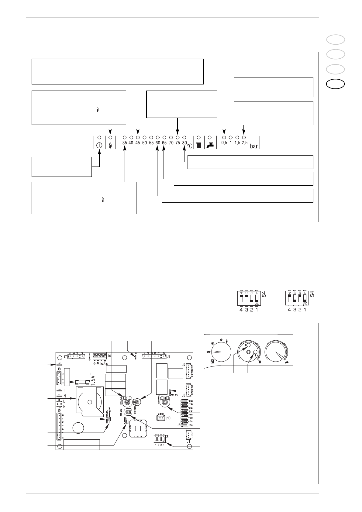
3.1.1 Fault finding
The indicator leds signalling irregular
and/or incorrect operation of the equipment are indicated in fig. 16.
3.1.2 Devices
The electronic board is equipped with the
following devices:
– “POT. RISC.” trimmer (10 fig. 17)
Sets the maximum heating power value.
To increase the value turn the trimmer
clockwise; to reduce the value turn the
trimmer anticlockwise.
– “POT. ACC.” trimmer (6 fig. 17)
Trimmer to vary the pressure level upon
ignition (STEP), of the gas valve.
According to the type of gas for which
the boiler is equipped, the trimmer must
be regulated so as to obtain a pressure
of approx. 3 mbar at the burner for
methane gas and 7 mbar for propane
gas (G31).
To increase pressure, turn the trimmer
clockwise; to reduce pressure, turn the
trimmer counterclockwise.
The slow ignition pressure level can be
set during the first 3 seconds following
burner ignition.
After setting the pressure level upon
ignition (STEP) according to the type of
gas, check that the pressure for heating is still at the value previously set.
– “MET-GPL” connector (7 fig. 17)
With the connector switched-off, the
3 CHARACTERISTICS
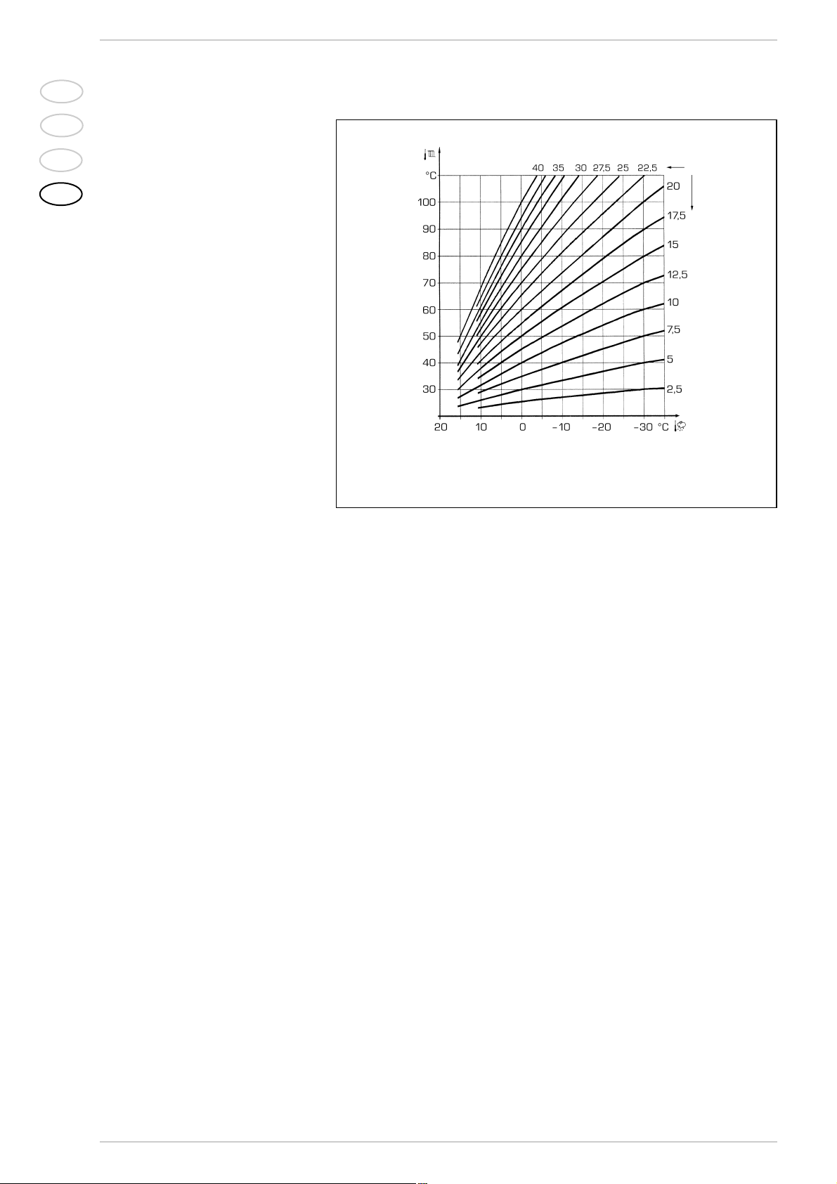
2.9.3 Gradient of
the characteristic
heating curve
The gradient of the characteristic heating
curve is imposed on the current value “15”
of Logica. Increasing the gradient as shown
in the drawing of fig. 15, the delivery temperature increases in correspondence to the
outside temperature.
2.10 EXTERNAL TEMPERATURE
SENSOR
The "Logica Remote Control" can be connected to an external temperature sensor
available a an optional extra (code
8094100).
This configuration ensures and maintains
the required temperature constant in the
room.
The ambient temperature is, in fact, indicted and evaluated as the calculated mean
of the value measured inside and outside
the dwelling.
For installation, follow the assembly instructions inserted in the package.
Fig. 15
Example: Choosing a gradient of 15 with an outside temperature
of –10°C we shall have a delivery temperature of 60°C.
IT
ES
PT
GB
109
boiler is set-up for NATURAL GAS; with
the connector switched-on, the boiler is
ready for LPG.
– “ANN. RIT.” connector (5 fig. 17)
In the heating phase, the electronic board
is programmed to include a burner technical delay interval of approx. 90 seconds,
which occurs both at system cold starting and at subsequent re-ignitions. The
aim is to overcome the problem of repeated ignitions and turning of f with very
short time intervals between. This could
occur in particular in systems presenting
high head losses.
At each restart after the period of slow
ignition, the boiler will set itself for about
1 minute at the minimum modulation
pressure, and will then move to the heating pressure value set.
When the connecting link is inserted,
both the programmed technical pause
and the period of operation at minimum
pressure in the startup phase will be cancelled. In this case, the times elapsing
between turning off and subsequent re-
ignition will depend on a temperature difference of 5°C detected by the SM sensor (heating flow sensor).
– DIP SWITCH (13 fig. 17)
Check that the cordless plugs are inserted in the position indicated:
Flashing red led,
communication fault
with “Logica Remote Control”
Green led of f if
power is cut-off
Flashing red led, water
pressure is too low (*)
Flashing red led, heating sensor fault
(SM)
Flashing red led,
plant safety
valve tripped (*)
Red led on, ignition blocked:
rotate selector CR/OFF/EST/INV/RESET
to release position
()
to restore operation
Flashing red led, safety stat tripped.
Rotate selector CR/OFF/EST/INV/RESET
to release position
()
to restore operation
Flashing red led, fan fault.
30 minutes af ter the fan has switched off,
the board will attempt a restart
(*)
When all 0.5 to 2.5 bar leds are off, check the
water pressure transducer connection.
Fig. 16
Flashing red led, D.H.W. sensor fault (SB)
Flashing red led, flame detection circuit fault
15
13
1
3
5
7
8
9
10
11
12
14
6
6
10
KEY
1 Ignition electrode earth faston
2 Ignition electrode faston
3 Fuse (1,6 AT)
4 Fuse(0,16 AT)
5 “ANN. RIT.” connector
6 “POT. ACC.” trimmer
7 Conector “MET-GPL”
8 D.H.W. potentiometer
9 Detector electrode faston
10 “POT. RISC.” trimmer
11 C.H. potentiometer
12 Selector CR/OFF/EST/INV/RESET
13 DIP SWITCH
14 Connector “Modureg Sel.”
15 Connector “Albatros”
NOTE: To gain access to trimmers (6) and (10), unscrew the central heating potentiometer knob
Fig. 17
Dewy 30/80 Dewy 30/130

IT
ES
PT
GB
110
– “Modureg Sel.” connector (14 fig. 17)
With the bridge disconnected the boiler
is predisposed to function with the SIT
gas valve, and with the bridge connected
it is predisposed to function with the
HONEYWELL gas valve.
– “Albatros” connector (15 fig. 17)
The bridge must always be disconnected.
It is connected only when multiple boilers
are installed in a sequence/cascade.
ATTENTION: It is essential that the operations described above be carried out by
authorized technical staff.
3.2 TEMPERATURE SENSOR
AND WATER PRESSURE
TRANSDUCER
Tables 3 - 3/a show the resistance values
(Ω) that are obtained on the sensor as the
temperature varies and the transducer
values obtained as the pressure varies.
When sensor (SM) is interrupted,
neither of the boiler's heating services
will function. With D.H.W. sensor (SB)
interrupted, the boiler will only work in
heating mode.
3.3 ELECTRONIC IGNITION
Ignition and flame detection is controlled by
two electrodes located on the burner.
These guarantee maximum safety with
intervention times, for accidental switching
off or gas failure, of within one second.
3.3.1 Operating cycle
Rotate the selector knob to summer or winter, and verify that green led ( ) lights up to
confirm the presence of voltage.
The burner must be ignited within 10
seconds.
However, it is possible for ignition
failures to occur, with consequent activation of signal indicating that the control box
has “locked out”.
– Gas failure
The control box runs through the cycle
normally sending electric power to the
ignition electrode. The electrode continues spark discharge for a maximum of
10 sec.If the burner does not light, the
lock-out indicator will light up.
This may occur upon first ignition or
after long periods of boiler lay-off when
there is air in the pipes. It may be caused
by the gas cock being closed or by one of
the valve coils having a break in the winding, so that the valve cannot open.
– Ignition electrode fails to spark
In the boiler, only the gas to the burner
is seen to open. After 10 sec. the warning light indicating equipment “lockout” lights up.
This may be due to a break in the wire of
the electrode or to the wire not properly
fastened to the electric terminal of the
control box;
– No detection of flame
The continuous spark discharge of the
electrode is noted starting from ignition
even though the burner is lit.
After 10 seconds have elapsed, the
sparks cease, the burner goes out, and
the warning light indicating equipment
“lock-out” lights up.
There could have a break in the wire of
the sensing electrode or the electrode
itself is touching earth: the electrode is
worn out and needs replacing. The control box is defective.
When there is a sudden voltage failure, the
burner shuts out immediately; when power
supply returns, the boiler will start up again
automatically.
3.4 FLOW SWITCH SAFETY VALVE
A flow switch safety valve (17 fig. 3) intervenes, blocking the operation of the burner if
the boiler is without water due to the formation of an air lock in the heat exchanger
or if the circulator is not working, or, model
“30/80”, because the “Aqua Guard Filter
System” is obstructed with impurities.
NOTE: If replacing the flow switch valve,
make sure that the arrow stamped on the
valve points in the same direction as the
flow of water.
3.5 SYSTEM AVAILABLE HEAD
For boilers with the standard fittings, the
residual head for the heating system on
the basis of rate of flow is represented in
the diagram in figure 18.
TABLE 3 (Sensors)
Temperature (°C) Resistance (Ω)
20 12.090
30 8.313
40 5.828
50 4.161
60 3.021
70 2.229
80 1.669
TABLE 3/a (Transducer)
Pressure Resistance (Ω)
(bar) min max
0 297 320
0,5 260 269
1 222 228
1,5 195 200
2167173
2,5 137 143
3108113
3,5 90 94
Fig. 18
1 HIGH TEMPERATURE ZONE
FLOW RATE (l/h)
RESIDUAL HEAD (mbar)
600
500
400
300
200
PREVALENZA RESIDUA (mbar)
10 0
0
200
vers. 30/80
vers. 30/130
140012001000800600400
PORTATA (l/h)
Dewy
1600

3.5.1 Head with total rate of flow
to other zones
In “30/130” versions using the second
and third zone kit, determine the head available to the zones as shown in the following
example:
Rate of flow calculated for zone 1 = 350 l/h
Rate of flow calculated for zone 2 = 400 l/h
Rate of flow calculated for zone 3 = 400 l/h
To obtain head available to zone 1, add the
total rate of flow to the other zones (in this
case zones 2 and 3): 400 l/h + 400 l/h =
800 l/h.
As shown in the graph (fig. 18/a) at the
800 l/h curve, head at 350 l/h for zone 1
= 180 mbar.
The same procedure may be applied to
other zones to obtain:
Zone 2 = 350 l/h + 400 l/h = 750 l/h.
As shown in the graph at the 800 l/h
curve, head at 400 l/h = 160 mbar.
Zone 3 = 350 l/h + 400 l/h = 750 l/h.
As shown in the graph at the 800 l/y
curve (curve E), head at 400 l/h = 160
mbar.
3.5.2 Head available with the low
temperature kit
In “30/130” versions using the low temperature kit, residual available head on the
basis of rate of flow is represented in the
graph in fig. 18/b.
111
IT
ES
PT
GB
Fig. 18/a
Fig. 18/b
1 HIGH AND 1 LOW TEMPERATURE ZONE
3 HIGH TEMPERATURE ZONES
FLOW RATE (l/h)
RESIDUAL HEAD (mbar)
FLOW RATE (l/h)
RESIDUAL HEAD (mbar)
A High temperature zone
B Low temperature zone with
mixer valve at 40°C
500
400
300
200
A= 0 l/h D= 600 l/h
B= 200 l/h E= 800 l/h
C= 400 l/h
DEWY 30/130
10 0
PREVALENZA RESIDUA (mbar)
0
500
400
300
200
10 0
PREVALENZA RESIDUA (mbar)
B
C
D
E
200
PORTATA (l/h)
A Zona alta temperatura
B Zona bassa temperatura con
valvola miscelatrice a 40°C
A
140012001000800600400
1600
DEWY 30/130
A
B
0
200
140012001000800600400
PORTATA (l/h)
1600
IT
ES
PT
GB
112
4.1 D.H.W. PRODUCTION
The preparation of hot water is guaranteed
by the glass storage tank unit with magnesium anode for the protection of the boiler
unit and inspection flange for its control and
cleaning.
The magnesium anode must be checked
annually and substituted when it is worn.
It is advisable to place a sluice gate at the
entrance of the D.H.W. tank unit which,
apart from the total closure, allows the regulation of the supply capacity.
If the boiler does not produce hot water,
make sure that the air has been released
by pressing on the manual vents after having switched off the main switch.
4.2 GAS VALVE
The boiler, is equipped standard with the
HONEYWELL VK 8115M gas valve (fig. 20).
4 USE AND MAINTENANCE
Fig. 20
KEY
1 Regulation intake
2 EV1-EV2 coils
3 Pressure inlet upstream
4 Pressure inlet downstream
5 OFF-SET
CR1
CR
TA
(5)
SONDA
SANITARIO
CONNETTORE J2
COPERTURA
TA
(6)
SB
(11)
SB
(12)
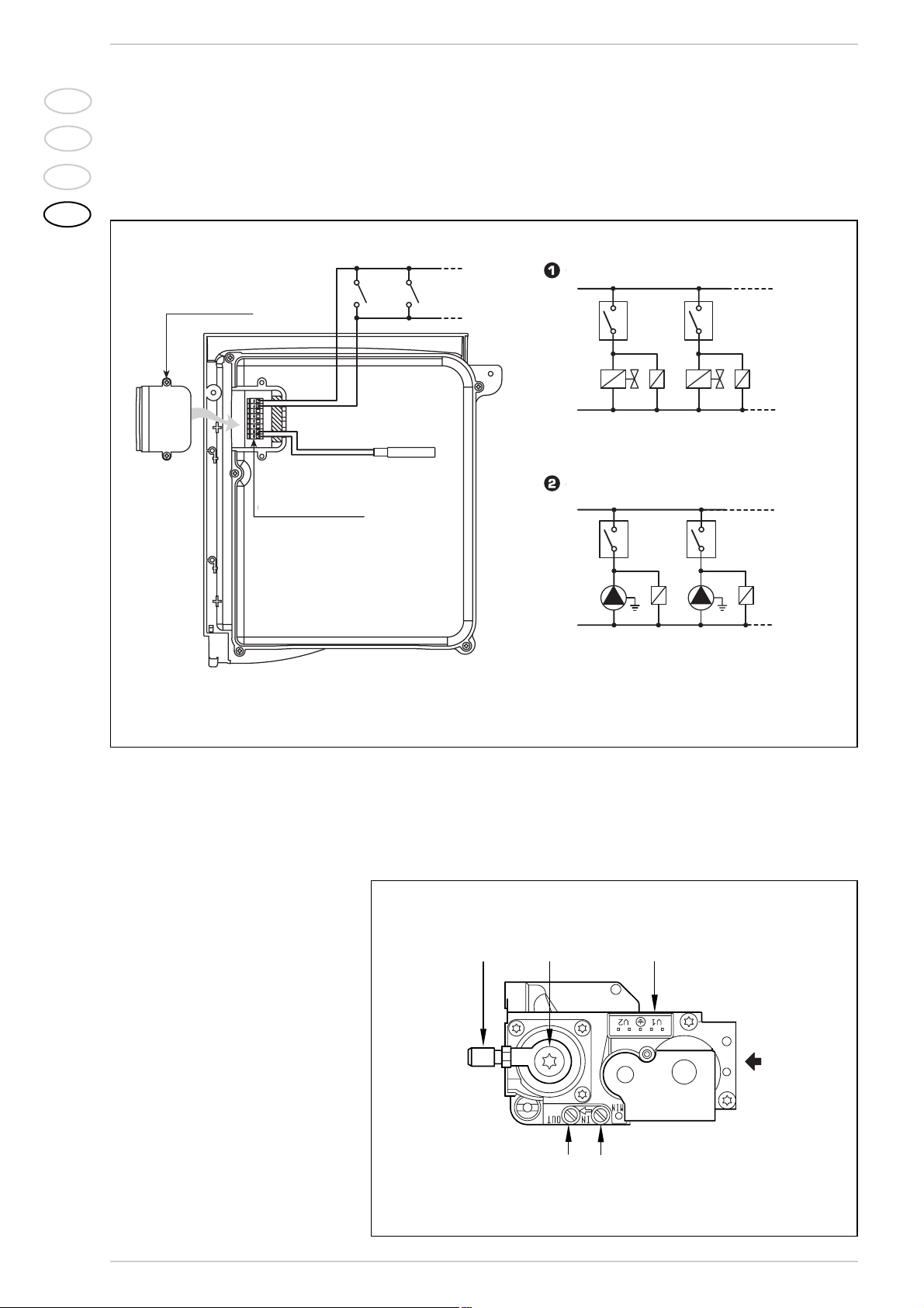
CIRCUITO CON VALVOLE DI ZONA
NOTA: I relé vengono impiegati solo nel caso
le valvole di zona siano prive di micro.
L
N
TA
TA1
VZ
R
VZ1
R1
CIRCUITO CON POMPE DI ZONA
L
N
TA
TA
P
R
P1
R1
KEY
TA-TA1 Zone room stat
VZ-VZ1 Zone gas valve
R-R1 Zone relay
CR-CR1 Zone microvalve or relay contact
P-P1 Zone pump
Fig. 19
COVER
CONNECTOR J2
CIRCUIT WITH ZONE VALVE
CIRCUIT WITH ZONE PUMP
NOTE: Relays are used only if the area valves have
no microswitches.
D.H.W.
SENSOR
3.6 SMOKE STAT
To protect the polypropylene conduit from
smoke the appliance is provided with an
exhaust thermostat (27 fig. 3 - 42 fig. 3/a).
3.7
MAINS ELECTRICITY
CONNECTION
Use a separate electricity supply to connect
the room stats and relative zone valves or
pumps.
The micro or relay contact connection is
made to TA-CR-SE (J2) connector of the circuit board after having removed the jumper
(fig. 19).
1
5
4
3
2

IT
ES
PT
GB
113
4.3 ADJUSTMENT
OF HEAT OUTPUT
FOR HEATING
To adjust boiler heat output for heating
purposes, i.e., modifying the setting made
at the factory which is approximately 17
kW, use a screwdriver to adjust the heating heat output trimmer (10 fig. 17).
To increase working pressure, turn the
trimmer clockwise; to reduce pressure,
turn the trimmer counterclockwise.
To determine boiler heat output setting,
check energy consumption by observing
the meter and then compare with the
values shown in Tables 4 - 4/a - 4/b; or
measure “air ∆p” with a digital pressure
gauge connected up as shown in fig. 21.
Compare values with those shown in
Tables 4 - 4/a - 4/b.
Fig. 21
91 2
3
4
76
5
KEY
1 Gas pressure intake
2 Gas valve
3 Mixer intake (–)
4 Ventilator intake (+)
5 Nozzle
6Fan
7 Air/gas mixer
9 Digital pressure gauge
0302010
∆p aria mm H
2
O
Potenza termica kW
25
20
10
15
50
40
60
5
30
50-30
°C
35
70
80-60
°C
0302010
∆p aria mm H
2
O
Potenza termica kW
25
20
10
15
504060
5
30
50-30
°C
35
70
80-60
°C
G20 G31
4.3.1 Diagram illustrating heat output in relation to “air ∆p”
TABLE 4/a - G20
* Air ∆p is measured during boiler operation using a differential pressure gauge connected to the ventilator intake.
** The gas consumptions refer to the calorific value at standard conditions at 15°C - 1013 mbar.
Variable heat output Air ∆p*
Gas consum.
**
(80-60°C) (50-30°C) (80-60°C) (50-30°C) G20
kW kW mm H
2
O mm H2Om3/h st
29,3 32,0 63,8 66,4 3,17
22,9 25,0 45,0 45,0 2,48
16,1 17,6 25,0 25,0 1,75
10,4 11,4 8,4 9,2 1,14
TABLE 4/b - G31
Variable heat output Air ∆p*
Gas consum.
**
(80-60°C) (50-30°C) (80-60°C) (50-30°C) G31
kW kW mm H
2
O mm H2O kg/h
29,3 32,0 68,4 70,4 1,52
21,8 23,4 45,0 45,0 1,19
15,4 16,6 25,0 25,0 0,84
10,4 11,4 9,2 9,5 0,55
Fig. 22
Heat outout (kW)
Air ∆p mm H
2
O
Heat outout (kW)
∆p de aire mm H
2
O

IT
ES
PT
GB
114
“∆p air” ADJUSTMENT
To measure “∆p air” simply con-
nect a dif ferential pressure
gauge with a decimal or Pascal
scale to the positive and negative tap, observing the symbols
(
Drawing 1
).
Sequence of operations:
1) Turn the heating power con-
trol trimmer clockwise as
far as it will go (
B – Drawing
2
) with the fan at its top
speed.
2) Attempt to achieve the “∆p
air” values given in the table
by adjusting the MAX trimmer on the fan board
(
Drawing 3
):
∆p air max.
3) Turn the heating power con-
trol trimmer anti-clockwise
as far as it will go (
B –
Drawing 2
) with the fan at
its top speed.
4) Attempt to achieve the “∆p
air” values shown in the
table using the “MIN” trimmer on the fan board
(
Drawing 3
):
∆p air min.
“∆p air-gas” ADJUSTMENT
To measure “∆p air-gas”, simply
connect the positive tap of the
differential pressure gauge to
the gas tap and the negative
tap to the corresponding tap on
the boiler (
Drawing 4
)
Always adjust gas pressure
with the fan at its top speed.
Sequence of operations:
1) Turn the heating power con-
trol trimmer anti-clockwise
as far as it will go (
B –
Drawing 5
) with the fan at
its top speed.
2) Open the gas capacity step
(
1 – Drawing 6
) all the way
so that the notch is in a horizontal position.
The boiler must always be calibrated while set on heating.
ATTENTION:
– On PROPANE – G31 boilers
it is a good idea to check
that the position of the GPL
bridge on the control board
is correct.
–
Diaphragm code 6028640
(
Drawing 7
) is assembled
on the “Dewy 25” model
functioning on PROPANE –
G31 only.
–
If the fan control board code
8260501 is replaced on
“Dewy” models running on
PROPANE – G31 it is very
important to remember to
cut the specified resistance
(
Drawing 8
).
Upon completion of the calibration procedure, check CO2values using a combustion analyser. If a difference which is more than 0.2 above
or below the values indicated in the table is found, it will be necessary to correct it:
– Use the OFFSET screw (
2 – Drawing 6
) to correct CO2at “MIN” output.
– Use the capacity step to correct CO
2
at “MAX” output (
1 – Drawing 6
).
Drawing 1
Drawing 2
Drawing 4
Drawing 6
Drawing 7
Drawing 8
Dewy 25 30
Natural gas (G20)
49,5 63,8
Propane (G31) 49,5 68,4
Dewy 25 30
Natural gas (G20)
7,1 8,4
Propane (G31) 7,1 9,2
Drawing 5
3) Adjust the gas valve OFFSET regulation (
2 – Drawing 6
), aiming
to achieve the “∆p air- gas” shown in the table:
Capacity step open
4) Using the capacity step (
1 – Drawing 6
), attempt to achieve the
“∆p air-gas” shown in the table:
Capacity step regulated
Dewy 25 30
Natural gas (G20) 7,3 7,0
Propane (G31) 8,1 10,1
Dewy 25 30
Natural gas (G20) 5,3 6,3
Propane (G31) 4,4 9,0
“Dewy 25” “Dewy 30”
CO
2
(Natural gas) CO2(Propane) CO2(Natural gas) CO2(Propane)
“MIN” output 9,3 10,2 9,0 10,1
“MAX” output 8,9 10,0 9,1 10,3
Drawing 3
MIN. MAX
“∆p air”
adjustment
4.4 BOILER CALIBRATION
Fig. 23
B
1
B
2

IT
ES
PT
GB
115
4.5 DISASSEMBLY OF
EXPANSION VESSEL
To disassemble the expansion vessel, proceed as follows:
– Make sure that the water has been emp-
tied out of the boiler.
– Unscrew the connection and the locknut.
– Remove the expansion vessel.
Before refilling the system, using a pressure gauge attached to the valve make sure
that the expansion vessel is preloaded at a
pressure of 0.8 to 1 bar.
4.6 CLEANING AND
MAINTENANCE
Preventive maintenance and checking of
efficient operation of equipment and safety
devices must be carried out exclusively by
authorized technical personnel.
During maintenance operations the
authorised technician must check that
the syphened drip is full of water (this
check is of importance particularly when
the generator has been out of use for a long
period of time). Filling is done via the special
opening (fig. 24).
4.6.1 Disassembly the control panel
and skirt cover lid (fig. 25)
To remove the cover, take out the screws
(1 – 2) that hold it in place on the instrument panel. Position side “A” of the bracket on the skirt side so that the instrument
panel is hooked on the side in order to
facilitate this operation.
4.6.2 Chimney sweep function
To carry out the verification of combustion
in the boiler, turn the selector and stop on
the position ( ) until the orange led ( )
starts to flash intermittently (fig. 29).
From that moment the boiler will start functioning in heating mode at the maximum
power, with switching off at 80°C and
restarting at 70°C.
Before activating the chimney sweep function make sure that the radiator valves or
eventual zone valves are open.
The test may be carried out also during hot
water functioning. To do so it is enough,
after having activated the chimney sweep
function, to take some hot water from one
or more taps; after a few minutes the
request of the hot-water service feeler is
activated and it automatically switches on
the led ( ). Even in this condition the boiler functions at the maximum temperature
always with the primary controlled between
80°C and 70°C. During the entire duration
of the testing the hot water taps must
remain open. After verifying the combustion
the boiler should be switched off by placing
the selector on the (OFF) position; then
return the selector to the desired function.
ATTENTION: After about 15 minutes the
chimney sweep function automatically
deactivates.
4.6.3 Cleaning the “Aqua Guard
Filter System” (fig. 27)
Model “30/80”, to clean the filter, close
the delivery/return on/off taps, turn off
the power to the control panel, remove the
casing and empty the boiler using the drain
provided. Place a container for collection
underneath the filter and proceed to clean
the filter, removing impurities and limestone deposits. Check the seal o-ring before
reassembling the cap with the filter.
Fig. 25
Side A
Side A
Fig. 26
Fig. 24
Fig. 27
FLASHING YELLOW LED
Lato A
Lato A
1
2
SPIA GIALLA INTERMITTENTE
IT
ES
PT
GB
116
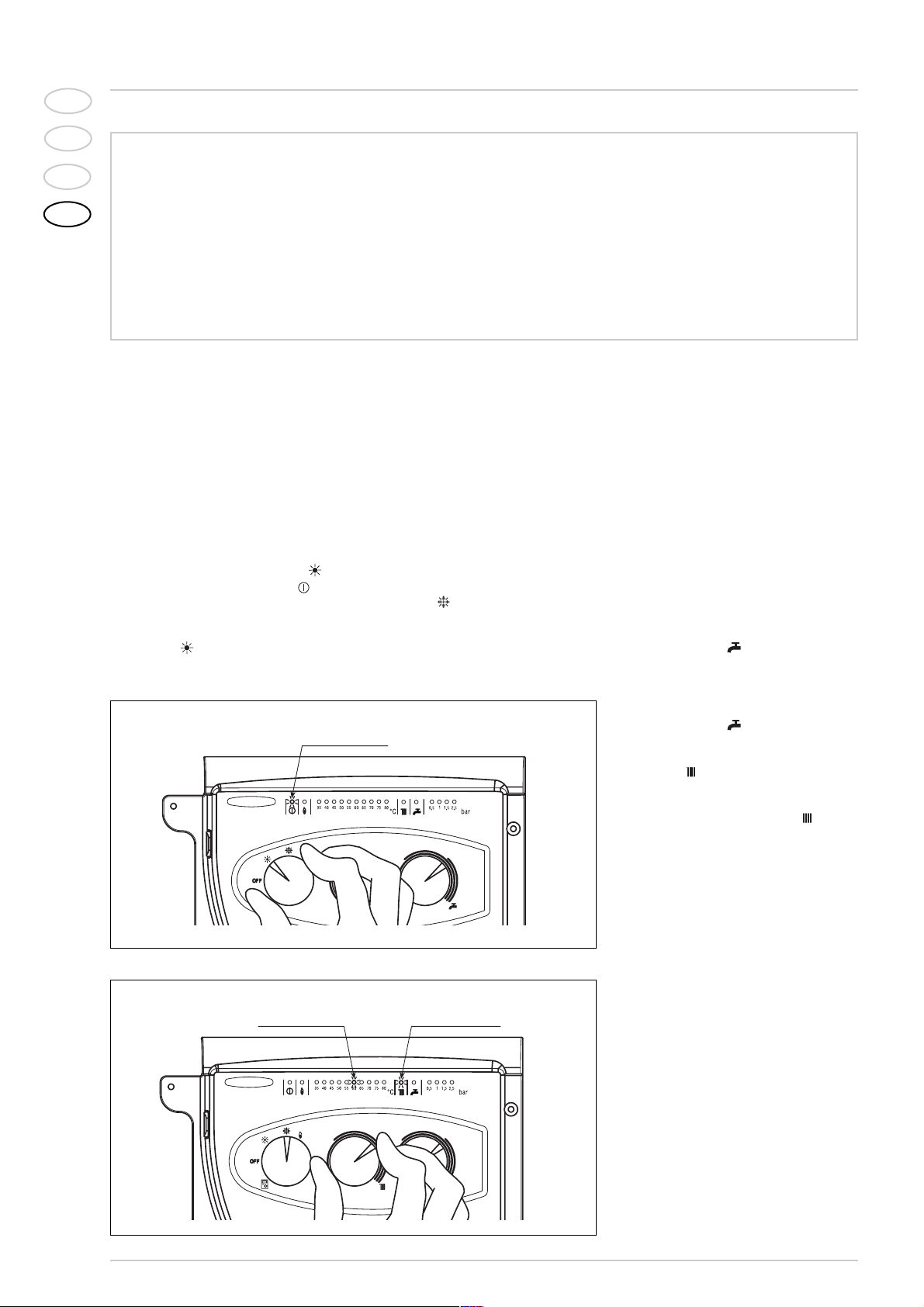
BOILER IGNITION (fig. 1)
Open the gas valve, lower the control panel
cover and activate the boiler by rotating the
selector knob to the summer positio ( ).
The lighting-up of the green led ( ) will
indicate that the apparatus is switched-on
and ready.
–
With the rotary switch in the summer
position ( ) the boiler will start-up
upon demand for domestic hot water,
and run at full power to reach the selected temperature.
The gas feeding pressure will then automatically vary to ensure that the required temperature is kept constant.
– With the rotary switch in the winter
position ( ) once the boiler has reached the value set on the heating potentiometer, it will start to modulate in automatically in order to supply the required
power output to the system. The opera-
tion of the boiler will be stopped through
the intervention of the thermostat or
“Logica Remote Control”.
TEMPERATURES ADJUSTMENT (fig. 2)
– The D.H.W. temperature can be adju-
sted by turning the knob of the D.H.W.
potentiometer ( ).
When there is a demand for hot water,
the set temperature is displayed on the
red led scale from 35÷80°C and the yellow domestic hot water led lights-up at
the same time ( ).
–
The C.H. temperature can be adjusted
by turning the knob of the C.H. potentiometer
( ).
The set temperature is indicated on the red led scale from
35÷80°C and the yellow heating led
lights up at the same time
().
If the
temperature of the blackflow water is
lower than around 55° C, condensation
of the combustion by-products is obtained, further increasing the efficency of
thew thermal exchange.
TURNING THE BOILER OFF (fig. 1)
To turn the boiler of f place the selector
knob on the OFF position. If the boiler is
not going to be used for a lengthy
period it is advised to turn of f the electricity supply, close the gas tap, and if
the temperatures foreseen are low,
empty the boiler and the hydraulic
system to avoid breakage in the tubes
due to the freezing of the water.
GAS CONVERSION
Should it be necessary to conver t the
appliance to a different gas from the one
for which the boiler has been equipped,
approach the technical staff.
WARNINGS
– In case of fault and/or incorrect equipment operation, deactivate it, without making any repairs or taking any direct
action. Contact an authorised technical staff.
– The installation of the boiler and any servicing or maintenance job must be carried out by qualified personnel. Under
no circumstances, the devices sealed by the manufacturer can be tampered with.
– It is absolutely prohibited to block the intake grilles and the aeration opening of the room where the equipment is
installed.
LIGHTING AND OPERATION
Fig. 1
Fig. 2
GREEN LED
RED LED YELLOW LED
USER INSTRUCTIONS
SPIA VERDE
SPIA GIALLASPIA ROSSA
IT
ES
PT
GB
117
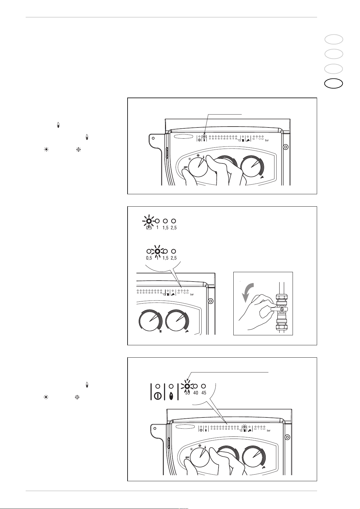
FAULT FINDING
–
Ignition lock-out
(fig. 3)
If the burners do not ignite, the red led
will light-up
( ).
To attempt a boiler restart, rotate the
selector knob to position
()
and release it immediately, placing it in the summer
()
or winter
()
operation posi-
tion
.
If the boiler lock-out re-occurs, contact
an authorised Service Centre.
–
Insufficient water pressure
(fig. 4)
If the red "0.5" bar led star ts flashing,
the boiler will not function.
To restart operation, rotate the charge
valve anticlockwise until the green "1
bar" led lights up.
ONCE THE FILLING HAS BEEN COMPLETED, CLOSE THE FILLING TAP.
If all the leds are off, call the local authorised Service Centre for technical assistance.
–
Safety stat trip
(fig. 5)
If the safety thermostat trips, the red
"35°C" led will start flashing. In order to
attempt a boiler restart, rotate the
selector knob to position ( ) and release immediately, returning it to the summer ( ) or winter ( ) position.
If the boiler lock-out occurs again, call
local authorised Service Centre for
technical assistance.
CLEANING
AND MAINTENANCE
Preventive maintenance and checking
of the efficient operation of the equipment and safety devices must be carried out exclusively by the authorized
technical staff.
The boiler is supplied with an electric
cable. Should this require replacement,
contact exclusively with the authorized
technical staff.
Fig. 3
Fig. 4
SPIA ROSSA INTERMITTENTE
IN CONDIZIONE DI SICUREZZA
SPIA VERDE IN CONDIZIONE
DI FUNZIONAMENTO
APRE
Fig. 5
RED LED
FLASHING RED LED
FLASHING RED LED
IN SAFETY CONDITION
GREEN LED IN OPERATING
CONDITION
OPEN
SPIA ROSSA
SPIA ROSSA INTERMITTENTE

IT
ES
PT
GB
118
–
Other anomalies
(fig. 6)
When one of the red
“40÷80°C”
leds
start flashing, switch-off the boiler and
then try to ignite again.
After 2 or 3 unsuccessful attempts, do
not try again but call authorised technical staff.
When “DEWY” is connected to the “Logica
Remote Control” regulator, the selector
CR/OFF/SUM/WIN/UNBLOCK must be
placed in the position ( ); the knobs of the
hot-water service heating potentiometers
do not have any ef fect and all of the functions will be managed by the regulator (fig.
7).
If the “Logica Remote Control” breaks
down, the boiler will function by placing the
selector on the ( o ), position, obviously without consequent control of the room
temperature.
No interior da tampa estão indicadas as
instruções de funcionamento (fig. 8). Cada
programação ou modificação é visualizada
e confirmada no display (fig. 9).
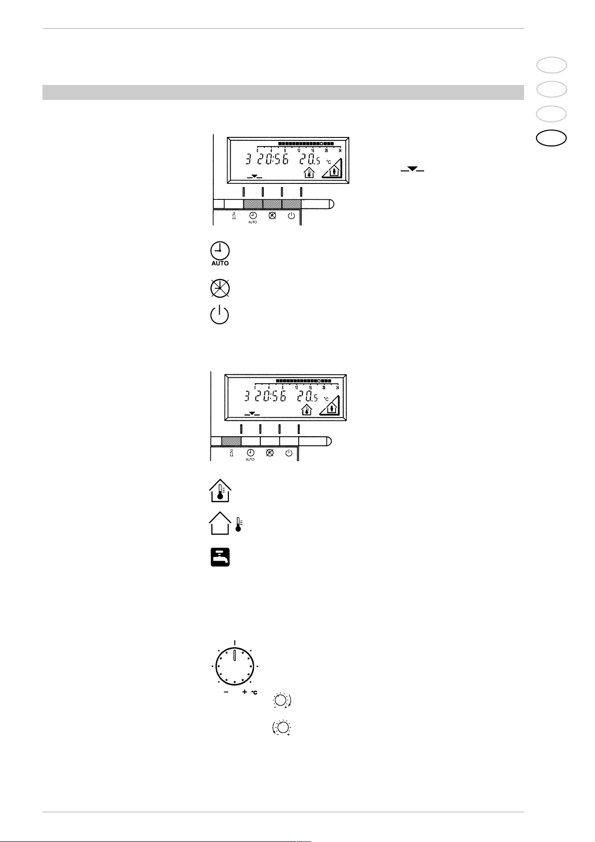
LOGICA REMOTE CONTROL
KEY
1 Display
2 Info button
3 Operating mode button: automatic operation
4 Operating mode button: manual operation
5 Operating mode button: availability
6 Cover with instruction compartment
7 Temperature knob
8 Presence button
Fig. 8
KEY
1 Display, time
2 Heating programme
3 Unit (%/C°)
4 Presence button display
5 External temperature
6 Ambient temperature
7 Holiday function
8 Operating mode
9 Line number/day
10 Burner on
11 Heating function
12 Domestic hot water/temperature/D.H.W. load
Fig. 9
Fig. 7
Fig. 6
FLASHING RED LED
SPIA ROSSA INTERMITTENTE
1
2
3
4
5
6
7
8
IT
ES
PT
GB
119
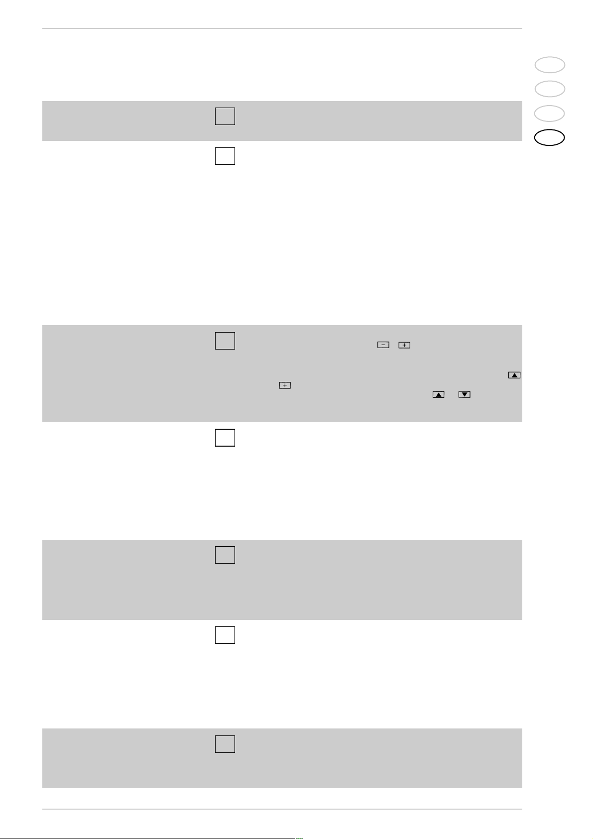
If it is too hot or too cold in your apartment, you can easily adjust the fixed
temperature with the temperature knob.
Before adjusting it again, however, allow the temperature to stabilise first.
Note: With the temperature knob you can only adjust the fixed temperature, whilst the redu-
ced temperature remains the same.
– Adjusting the temperature
If you turn the knob towards the + sign, the fixed temperature is
increased by about 1 °C for every notch.
If you turn the knob towards the - sign, the fixed temperature is
decreased by about 1 °C for every notch.
Before adjusting the temperature of the regulator, the thermostatic valves, which may be
present, have to be regulated to the desired temperature.
For every operation of the Info key the following list of items, one af ter the other, are
displayed. The thermo-feeler continues to
function independently of the display.
Day, hour, room temperature
External temperature*
Hot-water service temperature*
* This data appear only if the relative feeler is
connected or if they are transmitted by the
regulator of the boiler.
– Info key
(reference key grey colour)
The operating mode desired is selected by
pressing the relative key with the corresponding symbol. The choice is displayed with the
symbol
Automatic functioning: the heating functions automatically according to the heating programme entered. The programme may be excluded for brief periods with
the on-line key.
Manual functioning: the heating functions manually according to the choice made
with the on-line key.
Availability: the heating is deactivated.
– Selection of the operating mode
(reference keys grey colour)
ACTIVATING
During functioning the lid of the regulator must be closed.

IT
ES
PT
GB
120
– Setting the time
To set the current day of the week
(1 = Monday/7 = Sunday)
To set the current hour
To set the current minute
Once the hour is completed, the setting of the hour changes.
12
13
14
With and keys the current hour is regulated. Pressing these keys together, the
regulation is speeded up in an increasing sense.
If the rooms remain unused for a long period of time, the temperature can be reduced with the on-line key, in this way saving energy. When
the rooms are occupied again, press the on-line key to re-heat them.
The current choice is displayed on the display:
– On-line key
Fixed temperature heating
Reduced temperature heating
NOTA:
In automatic mode, the apparatus switches from the fixed temperature to the reduced temperature according to the temporal programme. The manual switching of the temperature is
done manually with the on-line key.
– Temperature regulation
Fixed temperature:
temperature when the rooms are occupied
(basic setting)
Reduced temperature:
temperature during periods of absence or night
Hot-water service temperature:
– desired temperature of hot-water service
– comfort temperature of the hot-water service
(with storage capacity boiler unit)
Reduced temperature of hot-water service (with storage capacity boiler unit):
temperature desired for hot-water service at reduced level.
To have access to the “reduced hot-water service temperature” parameter, press
the and keys at the same time for at least 5 seconds and then go along
the entered lines with the key until parameter 61 is reached. Regulate the value
with and
.
Before proceeding with the adjustment in the temperature on the regulator, the thermostatic valves, which may be present, have to be regulated to the desired temperature.
1
2
3
61
PROGRAMMING
For the programming the lid of the regulator must be open.
As soon as the cover is open,
the display and the key functions
are switched on.
The number in the square
represents the programme
lines that may selected with the
arrow keys.
You can set or display the following values:
• Temperatures up to
• Heating programme up to
• Day of the week and hour up to
• Current values up to
• Vacation period
• Return to the default values
1
3
4
11
12
14
15
17
18
19
The choice made will work in a permanent way when manually , carried out, instead, if
automatic it will work up to the next switching according
to the heating programme.

IT
ES
PT
GB
121
– Programme for hot-water service
(with storage capacity boiler unit)
Select the days that correspond with the heating phase.
1= Monday, ... 7 = Sunday/8 = hot-water service programme
Start of phase 1: heating with fixed modality
End phase 1: heating with reduced modality
Start phase 2: heating with fixed modality
End phase 2: heating with reduced modality
Start phase 3: heating with fixed modality
End phase 3: heating with reduced modality
Copying of the daily programme
By pressing this key it is possible to repeat the current heating programme
for the next day.
By pressing this key it is possible to repeat the current heating programme
for the previous day.
As a confirmation the following day is displayed.
4
5
6
7
8
9
10
11
With the Logic Remote Control it is possible to manage the temperature of boiler unit on two
levels (a comfort level and one at reduced temperature) in accordance with the programme
chosen with parameter 62 (load hot-water service). To have access to the parameter press
the and keys for at least 5 seconds and then go along the entered lines with the
key until parameter 62 is reached. At this point four different programmes may be selected
with o keys, with the following characteristics:
0 = 24 hours/ day - Hot water always available at the temperature set in parameter 3.
1 = standard - Hot water according to the daily heating programme. In the comfort periods
of the heating the temperature of the boiler unit is regulated at the value set via parameter 61.
2 = sservice suspended.
3 = second daily programme (8) - Everyday of the week the temperature of the hot-water ser-
vice is set according to programme B. In this case the programming is one for all the days
of the week and three periods of time are available. In the periods of time set, the temperature of the boiler unit is controlled via the temperature setting of parameter 61.
Start phase 1: preparation of the boiler unit to the comfort temperature
End phase 1: Temperature of boiler unit maintained at the reduced value
Start phase 2: Preparation of boiler unit to the comfort temperature
End phase 2: Temperature of boiler unit maintained at the reduced value
Start phase 3: preparation of boiler unit to the comfort temperature
End phase 3: Temperature of boiler unit maintained at the reduced value
5
6
7
8
9
10
– Heating/hot-water
service programme
With the heating programme it is possible to set the switching times of the temperature for a
period of a week. The weekly programme consists of 7 daily programmes. One daily programme allows 3 phases of heating. Each phase is defined by a starting time and a finishing time.
The n. 8 daily programme is for the hot-water service. If a phase is not required, the same starting and finishing time may be entered.

IT
ES
PT
GB
122
– Default values
To take the setting to the default values, press the and keys at the
same time for at least 3 seconds. As confirmation a sign will appear on the display.
19
ATTENTION
The values of the following line numbers previously entered will be lost.
• Temperature and time programme to
• Vacation period
1
10
18
1
0
– Error display
Ignition lock-out
Rotate selector CR/OFF/EST/INV/RESET on the "PLANET" control panel to the release position
()
to reset operation (fig. 3).
If the lock-out re-occurs, call an authorised Ser vice Centre.
Safety thermostat trip
Rotate selector CR/OFF/EST/INV/RESET on the "PLANET" control panel to the release position
()
to reset operation (fig. 5).
If the lock-out re-occurs, call an authorised Ser vice Centre.
Domestic hot water sensor fault (SB)
Call an authorised Service Centre.
67
68
69
70
192
193
195
Heating sensor fault (SM)
Call an authorised Service Centre.
Insufficient water pressure
Reset operation using the boiler charge valve (fig. 4).
Plant overpressure
Call an authorised Service Centre.
Safety thermostat trips
Call an authorised Service Centre.
The exhaust gas pressure switch trips
Call an authorised Service Centre.
No communication between the "Logica Remote Control" and the boiler.
Call an authorised Service Centre.
– Vacation function
To enter the number of days of absence.
In the display the vacation symbol will be shown ( ), on the left the day of activation (1 = Monday/7 = Sunday) and on the right the number of vacation days.
18
During the vacation the regulator will be on the availability mode.
When the set days have elapsed, the regulator will go on to the automatic function.
NOTE:
The vacation period may be cancelled by pressing a key of the operating mode.
– Current values
Display and setting of the gradient of the heating characteristics cur ve.
When the room temperature set is not reached choose the gradient
indicated in point 2.9.3
Display of the current boiler temperature.
Display of the current power of the burner and of the current operating mode
( = = heating/ = hot-water service)
15
16
17

DICHIARAZIONE DI CONFORMITA’ CALDAIE BASAMENTO A GAS
La FONDERIE SIME S.p.A., con riferimento all’art. 5 DPR n°447 del 6/12/1991 “Regolamento
di attuazione della legge 5 marzo 1990 n°46” ed in conformità alla legge 6 dicembre 1971 n° 1083
“Norme per la sicurezza dell’impiego del gas combustibile”, dichiara che le proprie caldaie basamento a
gas serie:
RX CE - RX 26 BF
RMG Mk.II
RS Mk.II
LOGO *
MISTRAL *
AVANT
KOMBIMAT CE
BITHERM - BITHERM BF
DUOGAS CE
DEWY *
EKO OF
sono complete di tutti gli organi di sicurezza e di controllo previsti dalle norme vigenti in materia e rispondono, per caratteristiche tecniche e funzionali, alle prescrizioni delle norme:
UNI-CIG 7271 (aprile 1988)
UNI-CIG 9893 (dicembre 1991)
UNI EN 297 per APPARECCHI A GAS DI TIPO B AVENTI PORTATA TERMICA ≤ 70 kW
EN 656 per APPARECCHI A GAS DI TIPO B AVENTI PORTATA TERMICA 70 ÷ 300 kW
EN 483 per APPARECCHI A GAS DI TIPO C AVENTI PORTATA TERMICA ≤ 70 kW.
La portata al sanitario delle caldaie combinate è rispondente alla norma:
UNI EN 625 per APPARECCHI AVENTI PORTATA TERMICA ≤ 70 kW
Le Caldaie a gas sono inoltre conformi alla:
DIRETTIVA GAS 90/396 CEE per la conformità CE di tipo
DIRETTIVA BASSA TENSIONE 73/23 CEE
DIRETTIVA COMPATIBILITÀ ELETTROMAGNETICA 89/336 CEE
DIRETTIVA RENDIMENTI 92/42 CEE
La ghisa grigia utilizzata è del tipo EN-GJL 150 secondo la norma europea UNI EN 1561.
Il sistema qualità aziendale è certificato secondo la norma UNI EN ISO 9001: 2000.
* Caldaie a basse emissioni inquinanti (“classe 5” rispetto alle norme europee UNI EN 297 e EN 483).
Legnago, 20 luglio 2004
Il Direttore Generale
ing. Aldo Gava
Fonderie Sime S.p.A. - Via Garbo, 27 - 37045 Legnago (Vr) - Tel. 0442 631111 - Fax Servizio Tecnico 0442 631292 - www.sime.it
TAGLIARE LUNGO LA LINEA TRATTEGGIATA

Rendimenti caldaie basamento a gas DPR 412/93 e DPR 551/99
MODELLO Potenza termica Portata termica Rendimento a carico nominale Rendimento al 30% del carico
kW kW minimo richiesto misurato minimo richiesto misurato
RX 19 CE 22,0 25,0 86,7 88,0 84,0 84,5
RX 26 CE 30,5 34,8 87,0 87,6 84,4 84,8
RX 37 CE 39,1 44,8 87,2 87,3 84,8 85,2
RX 48 CE 48,8 55,0 87,4 88,7 85,1 85,4
RX 55 CE 60,7 69,2 87,6 87,7 85,3 85,8
RX 26 BF 31,0 34,0 87,0 91,1 84,3 92,0
RMG 70 Mk.II 70,1 77,9 87,8 90,1 85,7 87,1
RMG 80 Mk.II 78,7 87,4 87,9 90,0 85,8 87,2
RMG 90 Mk.II 90,0 100,0 88,0 90,0 86,0 87,4
RMG 100 Mk.II 98,6 109,5 88,1 89,9 86,1 87,5
RMG 110 Mk.II 107,9 120,5 88,1 89,5 86,1 86,4
RS 129 Mk.II 129,0 145,9 88,2 88,4 86,3 86,7
RS 151 Mk.II 150,6 170,0 88,4 88,6 86,5 86,9
RS 172 Mk.II 172,2 194,2 88,5 88,7 86,7 87,1
RS 194 Mk.II 193,7 218,2 88,6 88,8 86,9 87,3
RS 215 Mk.II 215,2 242,1 88,7 88,9 87,0 87,5
RS 237 Mk.II 236,5 266,0 88,7 88,9 87,1 87,6
RS 258 Mk.II 257,8 290,0 88,8 88,9 87,2 87,7
RS 279 Mk.II 279,1 313,6 88,9 89,0 87,3 87,8
BITHERM 20/65 22,0 25,0 86,7 88,0 84,0 84,5
BITHERM 26/80 30,5 34,8 87,0 87,6 84,4 84,8
BITHERM 35/80 37,2 42,4 87,1 87,7 84,7 85,3
BITHERM 26/80 BF 31,0 34,0 87,0 91,1 84,3 92,0
DUOGAS 20/40 22,0 25,0 86,7 88,0 84,0 84,5
DUOGAS 26/40 30,5 34,8 87,0 87,6 84,4 84,8
LOGO 22 OF 23,7 26,0 89,7 91,0 87,1 90,6
LOGO 32 - 32/50 - 32/80 OF 31,6 34,8 90,0 90,7 87,5 90,5
MISTRAL 32 - 32/50 - 32/80 - 32/120 AD 31,9 34,3 87,0 93,0 84,5 93,6
KOMBIMAT 26/38 CE 29,0 32,2 86,9 90,0 84,4 86,5
AVANT 30/50 - 30/130 29,0 31,6 86,9 91,8 83,9 90,6
DEWY 30/80 - 30/130 29,3 30,0 92,5 97,7 98,5 106,6
EKO 3 OF - 3 OF PVA 21,2 23,3 89,5 90,9 89,5 92,8
EKO 4 OF - 4 OF PVA 31,6 34,8 89,7 90,9 89,7 92,8
EKO 5 OF 42,3 46,5 89,9 90,9 89,9 92,8
EKO 6 OF 53,1 58,3 90,1 91,4 90,1 92,9
EKO 7 OF 63,8 70,1 90,2 91,1 90,2 92,9
EKO 8 OF 74,2 81,5 90,3 91,1 90,3 92,9
EKO 9 OF 84,7 93,0 90,4 91,1 90,4 93,5
EKO 10 OF 95,2 104,6 90,5 91,1 90,5 93,5
EKO 11 OF 105,8 116,2 90,5 91,1 90,5 93,5
EKO 12 OF 117,0 128,0 90,6 91,7 90,6 93,3
NOTA: I dati sono stati ottenuti secondo le modalità di prova indicate dall’allegato E del DPR 412.


Fonderie Sime S.p.A - Via Garbo, 27 - 37045 Legnago (Vr)
Tel. + 39 0442 631111 - F a x +39 0442 631292 - www.sime.it
Cod. 6255540C - 10/05 - Documentation Dpt.
 Loading...