


Cod.
Low temperature wall mounted boiler
BRAVA SLIM 30 BFR
INSTALLATION AND SERVICING INSTRUCTIONS
EN
Gas Safety Certified AS/NZS 4552
LN: SAI-400197
CAUTION
This product must be installed exclusively by professionally qualified personnel in accordance with the requirements of
the standards AS/NZS 5601, AS/NZS 3500, AS/NZS 3000 (current version) of the local gas, electricity authorities and other
relevant legislation.
Fonderie SIME S.p.A.
6322894A - 10/2016 - R3

SAFETY WARNINGS AND REGULATIONS
RESTRICTIONS
m
m
WARNINGS
– After having removed the packaging make sure that
the product supplied is integral and complete in all
its parts. If this is not the case, please contact the
Dealer who sold the appliance.
– The appliance must be used as intended by
who is not responsible for any damage caused to
persons, animals or things, improper installation,
adjustment, maintenance and improper use of the
appliance.
– In the event of water leaks, disconnect the appliance
from the mains power supply, close the water
mains and promptly inform professionally qualified
personnel.
– Periodically check that the operating pressure of the
water heating system when cold is
kPa)
. If this is not the case, increase the pressure or
contact professionally qualified personnel.
– If the appliance is not used for a long period of time,
at least one of the following operations must be
carried out:
set the main system switch to "OFF";
-
-
close the gas and water valves for the water
heating system.
– In order to ensure optimal appliance operations
Sime
recommends that maintenance and checks
are carried out
TWICE A YEAR
1-1.2 bar (100-120
.
Sime
WARNINGS
–
It is recommended that all operators
carefully in order to use the appliance in a safe and
rational manner.
This manual
–
must therefore be kept for future reference and
must always accompany the appliance in the event
the appliance is transferred or sold to another
Owner or User or is installed on another system.
Installation and maintenance
–
must be carried out by a qualified company or by
a professionally qualified technician, or authorised
person, in accordance with the instructions
contained in the manual. The company or technician
will, at the end of installation operations, issue a
statement of compliance with national and local
Technical Standards and Legislation in force
– This appliance is not suitable for pool or SPA heating
is an integral part of the appliance. It
read this manual
of this appliance
d
IT IS FORBIDDEN
– Do not allow appliance to be used by children or
unassisted disabled persons.
– Do not use electrical devices or appliances such as
switches, electrical appliances etc if you can smell
fuel. If this should happen:
open the doors and windows to air the room;
-
-
close the gas isolation device;
-
promptly call for professional assistance.
– Do not touch the appliance with bare feet or with any
wet part of the body.
– Do not carry out any technical intervention or
cleaning operation before having disconnected the
appliance from the mains power by setting the main
switch to "OFF", and closing the gas supply.
– Do not modify the safety or adjustment devices
without authorization and instructions from the
manufacturer.
– Do not block the condensate drain (if present).
– Do not pull, detach or twist the electrical cables
coming out of the appliance even if the appliance is
disconnected from the mains power supply.
– Do not expose the boiler to atmospheric agents.
These boilers can also be installed in partially
covered areas, as per EN 15502, with a maximum
ambient temperature of 60°C and a minimum
ambient temperature of - 5°C. It is recommended
that the boiler is installed below weathered roofs,
on the balcony or in a protected niche, to protect it
from exposure to weathering agents (rain, hail and
snow). The boiler is equipped as standard with an
antifreeze function.
– Do not block or reduce the size of the ventilation
openings of the room where the appliance is
installed, if present.
– Remove the mains power and gas supply from the
appliance if the external temperature could fall
below ZERO (risk of freezing).
– Do not leave containers with flammable substances
in the room where the appliance is installed.
– Do not leave packaging material around since it
could be dangerous. Therefore dispose of it as
prescribed by legislation in force.
– Do not install the boiler in special environments
that may limit its optimum operation (e.g. marine
environment).
2

RANGE
MODEL CODE
Brava Slim 30 BFRi - (NATURAL GAS) 8112540
Brava Slim 30 BFRe - (NATURAL GAS) 8112541
COMPLIANCE
Our company declares that
with the following Australian Standards
– AS/NZS 5601 Gas Installations
– AS/NZS 3500 Water services, Sanitary plumbing and drainage
– AS/NZS 3000 Electrical installations, Buildings, structures
and premises
Brava Slim 30 BFR
boilers comply
TABLE OF CONTENTS
USER INSTRUCTIONS
TABLE OF CONTENTS 5
DESCRIPTION OF THE APPLIANCE
TABLE OF CONTENTS 13
INSTALLATION AND SERVICING
INSTRUCTIONS
TABLE OF CONTENTS 21
License Number:
SYMBOLS
a
f
d
m
WARNING
To indicate actions which, if not carried out correctly,
can result in injury of a general nature or may damage
or cause the appliance to malfunction; these actions
therefore require particular caution and adequate
preparation.
ELECTRICAL HAZARD
To indicate actions which, if not carried out correctly,
could lead to injury of an electrical nature; these
actions therefore require particular caution and
adequate preparation.
IT IS FORBIDDEN
To indicate actions which MUST NOT BE carried out.
CAUTION
To indicate particularly important and useful
information.
SAI-400197
.
3

4

TABLE OF CONTENTS
USER INSTRUCTIONS
1 USING THE BOILER BRAVA SLIM 30 BFR 6
1.1 Control panel ...................................6
1.2 Preliminary checks ..............................7
1.3 Ignition ........................................7
1.4 Adjusting the heating temperature .................7
1.5 Fault / malfunction codes.........................8
2 SHUTDOWN 8
2.1 Temporary shutdown ............................8
2.2 Shutting down for long periods ....................8
3 MAINTENANCE 9
3.1 Adjustments....................................9
3.2 External cleaning................................9
3.2.1 Cleaning the cladding................... 9
4 DISPOSAL 9
4.1 Disposal of the equipment (European Directive
2002/96/CE) ....................................9
5 HANDOVER INSTRUCTIONS 10
6 SERVICE RECORDS 10
5

1 USING THE BOILER BRAVA SLIM 30 BFR
21
2
1.1 Control panel
NOTE:
seconds generates a fault on the display without preventing
boiler operation. The warning disappears when normal
conditions are restored.
2
DISPLAY
l
n
d
t
f
F
v
Fig. 1
1
FUNCTIONAL BUTTONS
If pressed once or more than once for at least 1 second
y
during normal operation, this button allows the user
to change the boiler operating mode in a cyclical
sequence (Stand-by – Summer – Winter). If the boiler is
experiencing a fault which can be reset, it allows boiler
operation to be unblocked. (Note: the "SUMMER" mode
is not applicable to this boiler).
In "parameter setting", the user can scroll through the
(
parameter index (decreasing) by pressing this button.
During normal operation, pressing this button displays
t
the flow temperature set point which can be between 20
and 80°C. In "parameter setting", the user can scroll
through the parameter index (increasing) by pressing
this button.
During normal operation, pressing this button allows
<
the user to reduce the flow temperature set point. In
"parameter setting/display", the user can modify the
parameter setting or value (decreasing) by pressing this
button.
During normal operation, pressing this button allows
>
the user to increase the flow temperature set point. In
"parameter setting/display", the user can modify the
parameter setting or value (increasing) by pressing this
button.
Programming connector cover plug.
c
p
A
z
E
m
pressing any one of these buttons for more than 30
“SUMMER”
If the symbols
that the chimney sweep function is active.
“WINTER”
operating in "Winter" mode. If no operating modes have
been enabled both symbols
“RESET REQUIRED”
having repaired the fault, normal boiler operation can be
restored by pressing the button
“HEATING”
operation or during the "chimney sweep function It
flashes during the selection of the heating set point.
“BLOCK” DUE TO NO FLAME
“FLAME PRESENCE"
“POWER LEVEL"
the boiler is operating.
“PARAMETER"
parameter setting/display, or "info" or "counter", or in
"activated alarms" (history).
“ALARM"
number specifies the cause which generated the alarm.
“CHIMNEY SWEEP"
sweep function" has been activated.
"ECO", ALTERNATIVE ENERGY SOURCES
indicates that there is a solar system available.
CAUTION
– Access to the control panel of model
– On completion of the operations, refit the panel on
a
1
. The symbol for "Summer" mode is displayed.
and n are flashing, this indicates
l
. This symbol appears when the boiler is
and n will be off.
l
. The message indicates that after
.
y
. This symbol lights up during heating
.
.
. This indicates the power level at which
. This indicates that the user may be in
. This indicates that a fault has occurred. The
. This indicates that the "chimney
. Where active, it
Brava Slim
30 BFRe
removing panel (2).
the control panel and secure fully.
is possible after loosening screw (1) and
b
Fig. 2
6

1.2 Preliminary checks
Commissioning of the
out by professionally qualified technicians, after which the boiler
can operate automatically. It may, however, be necessary for the
user to start the appliance autonomously without involving a
technician: for example, after a holiday.
First of all check that the gas isolation and water system valves
are open.
Brava Slim 30 BFR
boiler must be carried
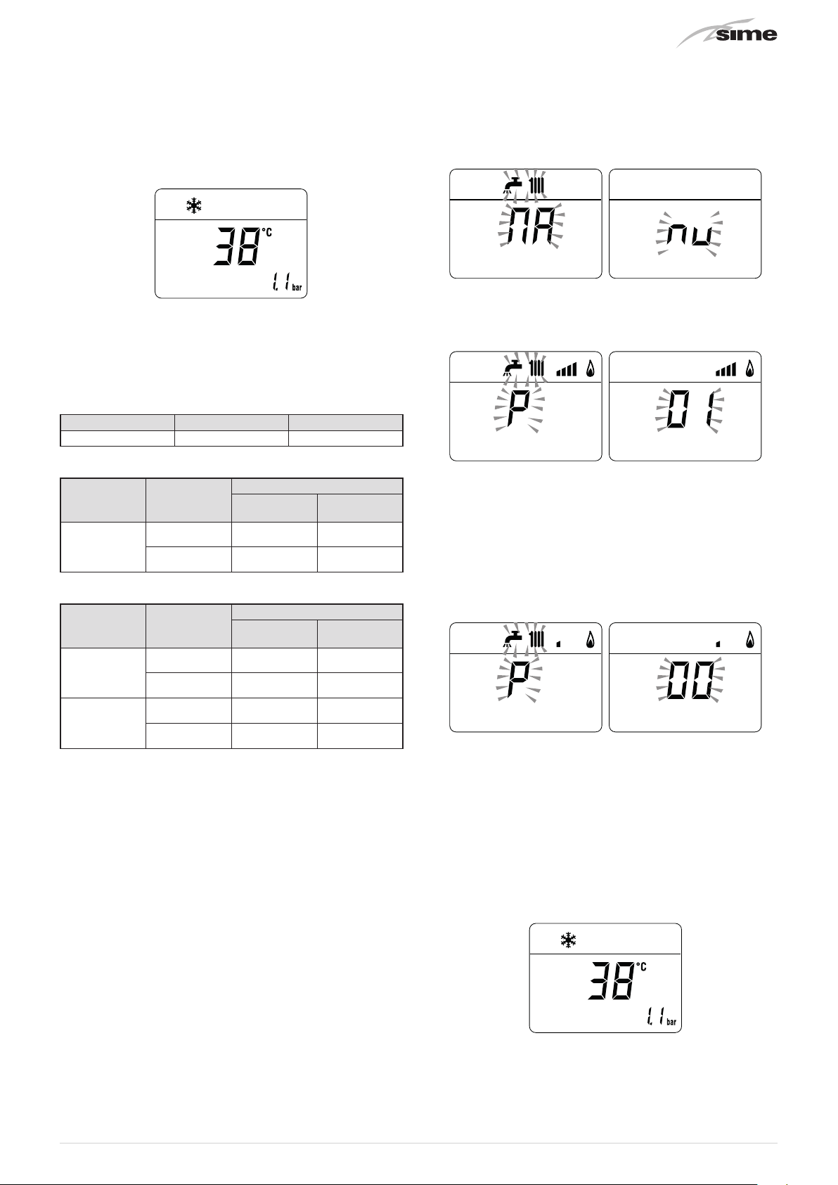
1.3 Ignition
After having carried out the preliminary checks, perform the
following to start the boiler:
– set the main system switch to "ON" in order for the display to
show the pressure level in the system during refilling
make sure that the operating mode is set to "Stand-by";
–
not the case, press the button
been selected
ON
– on the display (1), check that the heating system pressure
when cold is
filling valve, which is to be prearranged on the system return,
and fill until a pressure of
the display (1)
– close the filling valve
1-1.2 bar (100-120 kPa)
until "Stand-by" mode has
y
. Otherwise, open the
1-1.2 bar (100-120 kPa)
if this is
Fig. 3
is shown on
– set the room thermostat to the required temperature, or
if the system is equipped with a timed programmer or
external temperature controller, check that this is ON and set
accordingly.
1.4 Adjusting the heating temperature
If the heating temperature is to be increased or decreased,
press the button
desired temperature is reached. The temperature can be set to
between 20 and 80°C.
followed by the buttons > or < until the
t
1
Fig. 4
– select the "WINTER" l operating mode by pressing the
button twice. the value of the delivery sensor detected at
y
that moment will appear on the display
7
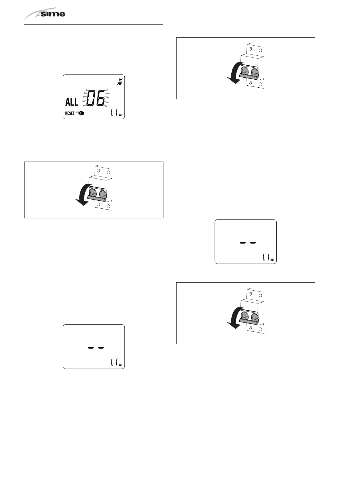
1.5 Fault / malfunction codes
OFF
OFF
OFF
If a fault/malfunction is detected during boiler operation, the
"ALL"
message
code (eg.
If the message
button
y
operating conditions are restored.
will appear on the display followed by the fault
"06"
- no flame detected).
d
for more than 3 seconds and check that the normal
also appears, press and hold the
– set the main system switch to "OFF"
– close the gas valve.
Fig. 6
If this operation is not successful,
be made, therefore:
– close the gas isolation valve
– set the main system switch to "OFF"
– contact the Qualified Technical Personnel.
m
CAUTION
In case of failure, the fault code appears on the display.
The list of all fault codes, with their descriptions, can
be found in the section Commissioning.
ONLY ONE MORE ATTEMPT
2 SHUTDOWN
can
Fig. 5
m
CAUTION
If the outside temperature might fall below ZERO,
since the appliance is equipped with an "antifreeze
function" and the "anti-freeze kit to -15°C":
– PUT THE BOILER INTO STAND-BY
– leave the main system switch set to "ON" (boiler is
powered)
– leave the gas valve open.
2.2 Shutting down for long periods
If the boiler is to be left unused for a long period, the following
operations need to be carried out:
– press and hold the button
"WINTER mode"
the boiler into stand-by
– set the main system switch to "OFF"
or twice if in "SUMMER mode" l to put
n
for at least 1 second, once if in
y
"- -"
will appear on the display
2.1 Temporary shutdown
If the user wishes to interrupt boiler operation, press and hold
the button
mode"
n
"- -"
will appear on the display.
f
If the user is away temporarily, for a weekend, short trip etc and
if the outside temperature is at ZERO:
– press and hold the button
or twice if in "SUMMER mode"
by
for at least one second, once if in "WINTER
y
or twice if in "SUMMER mode" l.
ELECTRICAL HAZARD
The boiler will still be powered.
once if in "WINTER mode" n
y
to put the boiler into stand-
l
– close the gas valve
– close the heating system isolation valves
– drain the heating system if there is the risk of freezing.
m
CAUTION
Contact the Qualified Technical Personnel if the
procedure described above cannot be easily carried
out.
Fig. 7
8

3 MAINTENANCE
4 DISPOSAL
3.1 Adjustments
For the appliance to operate correctly and efficiently it is
recommended that the User calls upon the services of a
Professionally Qualified Technician to carry out
maintenance.
m
3.2 External cleaning
3.2.1 Cleaning the cladding
When cleaning the cladding, use a cloth dampened with soap
and water or alcohol for stubborn marks.
d
CAUTION
Maintenance interventions must ONLY be carried out
by professionally qualified personnel who will follow
the indications authorised in the INSTALLATION AND
MAINTENANCE INSTRUCTIONS.
IT IS FORBIDDEN
to use abrasive products.
BI-ANNUAL
4.1 Disposal of the equipment (European
Once it reaches the end of its operating life, the equipment
MUST BE RECYCLED in line with current legislation.
It can be handed over to recycling centres, if there are any, or to
retailers that offer this service.
Recycling prevents potential damage to the environment and
health. It allows to recover a number of recyclable materials,
with considerable savings in terms of money and energy.
d
Directive 2002/96/CE)
IT IS FORBIDDEN
dispose of the product with urban waste.
9
5 HANDOVER INSTRUCTIONS
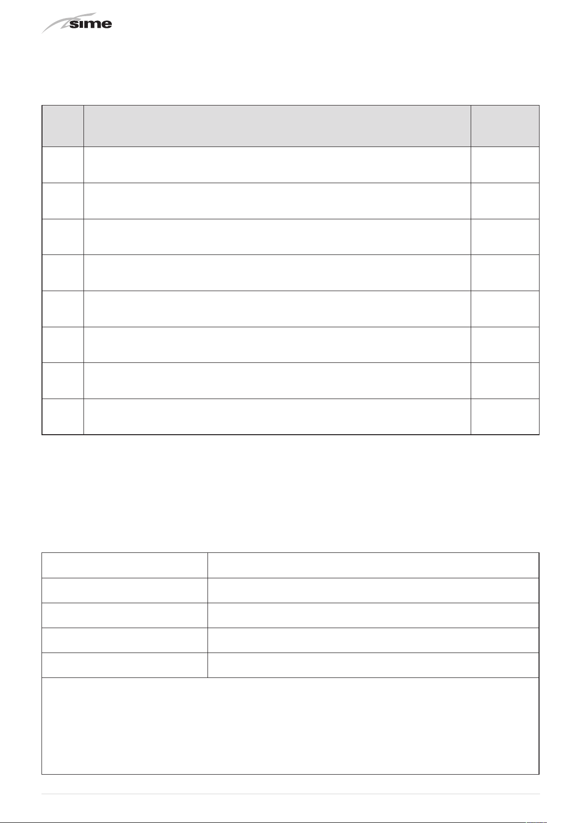
N° Description
1 Fill in all the details on this Boiler manual.
Instruct the owner /users on the correct operation of the heating system, including how to turn the
2
systems on and off, adjust the time and temperature settings.
3 Instruct how to turn the heating system off in summer and on for winter.
Locate all major components, understand their functions and how to turn them on and off, their
4
functions and how to check and turn them on or off. Simple fault resolution i.e. power on.
5 Instruct how to check and remove air in the radiators. Provide a bleed key.
When done
Turn ON gas, bleed air out at the isolation valve unions. Reseal and check for gas leaks.
6
Turn gas OFF.
7 Underline the importance of these SERVICE RECORDS, keeping them safe & accessible.
Recommend that the boiler should be serviced at/ before the start of winter next year and then every
8
two years.
For any needs please contact Reece Customer Care 1800 080 055 or customercare@reece.com.au.
6 SERVICE RECORDS
Service – 1 – Year 1
Service technician
Service Company
Date
Name
PIC Licence No.
Contact phone number
Work Completed
Notes
10

Service – 2 – Year 3
Date
Service technician
Service Company
Contact phone number
Work Completed
Notes
Service – 3 – Year 5
Service technician
Service Company
Contact phone number
Name
Date
Name
PIC Licence No.
PIC Licence No.
Work Completed
Notes
Service – 4 – Year 7
Service technician
Service Company
Contact phone number
Work Completed
Notes
Date
Name
PIC Licence No.
11

Service – 5 – Year 9
Date
Service technician
Service Company
Contact phone number
Work Completed
Notes
Service – 7 – Year 11
Service technician
Service Company
Contact phone number
Name
Date
Name
PIC Licence No.
PIC Licence No.
Work Completed
Notes
Service – 8 – Year 13
Service technician
Service Company
Contact phone number
Work Completed
Notes
Date
Name
PIC Licence No.
For any needs please contact Reece Customer Care 1800 080 055 or customercare@reece.com.au.
12

TABLE OF CONTENTS
DESCRIPTION OF THE APPLIANCE
7 DESCRIPTION OF THE APPLIANCE 14
7.1 Characteristics ................................14
7.2 Check and safety devices ........................14
7.3 Identification ..................................14
7.4 Structure .....................................15
7.4.1 Brava Slim 30 BFRi ........................15
7.4.2 Brava Slim 30 BFRe ........................16
7.5 Technical features..............................17
7.6 Main water circuit ..............................18
7.7 Sensors ......................................18
7.8 Expansion vessel ...............................18
7.9 Circulation pump...............................18
7.10 Control panel ..................................19
7.11 Wiring diagram ................................20
13

7 DESCRIPTION OF THE APPLIANCE
7.1 Characteristics
Brava Slim 30 BFR
mounted boilers which
The model
30 BFRe
model
protected against atmospheric agents. The main elements
choices made by
– the atmospheric burner combined with a copper heat
exchanger for heating and a rapid heat exchanger for DHW
– the sealed combustion chamber, with respect to the room
where the boiler is installed
– the command and control microprocessor electronic board
provides efficient management of both heating and hot water
production. It can also be connected to a remote control
with an Open Therm protocol or to room thermostat and/or
external sensor. If connected to an external sensor, the boiler
temperature varies on the basis of the external temperature
according to a selected optimal climatic curve providing
significant energy and economic savings.
Other special features of the
– the anti-freeze function which activates automatically if the
temperature of the water inside the boiler falls below the
threshold of the value set at parameter "PAR 10" and , if there
is an external sensor, if the external temperature falls below
the threshold of the value set at parameter "PAR 11"
– the anti-blocking function of the pump and diverter valve, this
activates automatically every 24 hours if no request for heat
has been made
– the chimney sweep function lasts 15 minutes and makes the
job of the qualified technician easier when measuring the
parameters and combustion efficiency
– screen display of the operating and self-diagnostic
parameters with error code display when the fault occurs.
This makes repair interventions easier and allows appliance
operation to be restored correctly.
are last generation low temperature wall
Sime
has produced for heating ONLY.
30 BFRi
is designed for installation in rooms, while
is designed specifically for outdoor installation,
Sime
for the
Brava Slim 30 BFR
Brava Slim 30 BFR
boilers are:
boilers are:
d
a
IT IS FORBIDDEN
to commission the appliance with safety devices which
do not work or which have been tampered with.
WARNING
Safety device may only be replaced by professional
Sime
qualified personnel using
original spare parts.
7.3 Identification
The
Brava Slim 30 BFR
1 Packaging label:
packaging and provides a code, the serial number of the
boiler and the bar code
2 Technical Data Plate:
the boiler and provides the technical specification, appliance
performance and any other information required by law.
1
2
boilers can be identified by means of:
this is located on the outside of the
this is located inside the front panel of
1
7.2 Check and safety devices
The
Brava Slim 30 BFR
check and safety devices:
– thermal safety thermostat 100°C
– 3 bar (300 kPa) relief valve
– heating water pressure transducer
– delivery sensor.
NOTE:
the proper fan operation of this boiler is checked
electronically from the control panel. Then the use of an air
pressure switch is not required.
boilers are equipped with the following
KEY:
1
Packaging label
2
Technical Data Plate
m
CAUTION
Tampering with, removing or failing to display the
identification plate or carrying out any other operation
which does not allow safe identification of the product
or which may hinder installation and maintenance
operations.
2
Fig. 8
14

7.4 Structure
1
2
3
5
4
7.4.1
Brava Slim 30 BFRi
15
14
13
12
11
6
1
Fan
2
Dual sensor (thermal safety/delivery)
3
Combustion chamber
4
Ignition/detection electrode
5
Control panel
6
Gas valve
7
System relief valve
8
Boiler drain
9
System pump
10
Water pressure transducer
11
Automatic bleed valve
12
Burner
13
Primary heat exchanger
14
Expansion vessel
15
Smoke outlet
7
10
9
8
Fig. 9
15

7.4.2
Brava Slim 30 BFRe
17
16
15
1
14
2
13
3
4
5 6
1
Fan
2
Dual sensor (thermal safety/delivery)
3
Combustion chamber
4
Ignition/detection electrode
5
Control panel
6
Gas valve
7
System relief valve
8
Boiler drain
9
System pump
10
Water pressure transducer
11
Automatic bleed valve
12
Burner
13
Primary heat exchanger
14
Expansion vessel
15
Coaxial duct
16
Smoke outlet
17
Air inlet
12
11
10
7
9
8
Fig. 10
16

7.5 Technical features
DESCRIPTION
CERTIFICATIONS
Country of intended installation AUS
Fuel NATURAL GAS / UNIVERSAL LPG
SAI GLOBAL number SAI-400197
Class NO
x
HEATING PERFORMANCE
HEAT INPUT
Nominal MJ/h 120
Minimum MJ/h 60.0
HEAT OUTPUT
Nominal (80-60°C) kW 28.1
Minimum NATURAL GAS (80-60°C) kW 13.1
Minimum UNIVERSAL LPG (80-60°C) kW 9.2
EFFICIENCY
Max useful efficiency (80-60°C) % 93.7
Min useful efficiency (80-60°C) % 87.3
ELECTRICAL SPECIFICATIONS
Power supply voltage V 230
Frequency Hz 50
Absorbed electrical power W 113
Electrical protection degree IP X5D
COMBUSTION DATA
Smoke temperature at Max/Min flow (80-60°C) °C 150/100
Smoke flow Max/Min g/s 19/19
CO
2
at Max/Min flow rate (NATURAL GAS) % 7.1/2.3
CO
2
at Max/Min flow rate (UNIVERSAL LPG) % 7.8/2.7
NOZZLES GAS
Number of nozzles No. 13
Nozzle diameter (NATURAL GAS-UNIVERSAL LPG) mm 1.5/0.86
Gas consumption at Max/Min flow rate (NATURAL GAS) m
Gas consumption at Max/Min flow rate (UNIVERSAL
LPG)
Gas supply pressure (NATURAL GAS/UNIVERSAL LPG)
3
/h 3.17/1.59
3
/h 1.25/0.63
m
mbar 11.3/27.5
kPa 1.13/2.75
TEMPERATURE PRESSURE
Max operating temperature °C 85
Heating adjustment range °C 20÷80
Max operating pressure
bar 3.0
kPa 300
Water content in boiler l 3.65
Brava Slim BFR
30 BFRi
-
30 BFRe
5 (< 70 mg/kWh)
Lower Heat Output (Hs)
NATURAL GAS Hs.
37.78 MJ/m3 (15°C, 1013 mbar/101.3 kPa) -
UNIVERSAL LPG Hs.
95.65 MJ/m3 (15°C, 1013 mbar/101.3 kPa)
17

7.6 Main water circuit
TR
Resistance R (
0 800 1000 1200 1400 1600600400200
100
200
300
400
500
1
2
3
4
0°C 1°C 2°C 3°C 4°C 5°C 6°C 7°C 8°C 9°C
0°C
27279
26135
25044
24004
23014
22069
21168
20309
17959
17245
16563
15912
15289
14694
14126
10°C
20°C
30°C
40°C
50°C
60°C
70°C
80°C
90°C
100°C
12090
8313
5828
4161
3021
2229
1669
1266
973
11634
8016
5630
4026
2928
2164
1622
1232
11199
7731
5440
3897
2839
2101
1577
1199
10781
7458
5258
3773
2753
2040
1534
1168
10382
7196
5082
3653
2669
1982
1491
1137
9999
6944
4913
3538
2589
1925
1451
1108
13582
9633
6702
4751
3426
2512
1870
1411
1079
9281
6470
4595
3319
2437
1817
1373
1051
19489
13062
8945
6247
4444
3216
2365
1766
1336
1024
18706
12565
8622
6033
4300
3116
2296
1717
1300
998
Ω)
5
M G R
KEY:
M System delivery
R System return
G Gas supply
S Safety valve outlet
1
Fan
2
Heat exchanger (mono-thermal)
3
Dual sensor (thermal safety/delivery)
4
Combustion chamber
5
Gas valve
6
Automatic bleed valve
7
Pump
8
System relief valve
9
Water pressure transducer
10
Boiler drain
11
System expansion vessel
11
7.8 Expansion vessel
The expansion vessel installed on the boilers has the following
characteristics:
9
8
76
Description U/M
Total capacity l 9.0
S
10
Prefilling pressure
Useful capacity l 5.0
Maximum system content (*) l 124
kPa 100
bar 1.0
Brava Slim BFR
30 BFRi
(*) Conditions of:
Average maximum temperature of the system 85°C
Start temperature at system filling 10°C.
Fig. 11
m
CAUTION
– For systems with water content exceeding the
maximum system content (as indicated in the
table) an additional expansion vessel must be
prearranged.
– The difference in height between the relief valve
and the highest point of the system cannot exceed
6 metres. If the difference is greater than 6 metres,
increase the prefilling pressure of the expansion
vessel and the system when cold by 0.1 bar (10 kPa)
for each meter increase.
7.9 Circulation pump
The flow-head performance curve available for the heating
system is shown in the graph below.
RESIDUAL HEAD (mbar/kPa)
7.7 Sensors
The sensors installed have the following characteristics:
– Dual sensor (thermal safety/output) NTC R25°C; 10kΩ β25°-
85°C: 3435
– domestic hot water sensor NTC R25°C; 10kΩ β25°-85°C: 3435
– external sensor NTC R25°C; 10kΩ β25°-85°C: 3435
Correspondence of Temperature Detected/Resistance
Examples of reading:
TR=75°C → R=1925Ω
TR=80°C → R=1669Ω.
18
/50
/40
/30
/20
/10
0
m
30 BFR
FLOW (l/h)
Fig. 12
CAUTION
The appliance is equipped with a by-pass which
ensures water circulation in the boiler when the
thermostatic valves or manual valves are used in the
system.

7.10 Control panel
21
2
Fig. 13
1
FUNCTIONAL BUTTONS
If pressed once or more than once for at least 1 second
y
during normal operation, this button allows the user
to change the boiler operating mode in a cyclical
sequence (Stand-by – Summer – Winter). If the boiler is
experiencing a fault which can be reset, it allows boiler
operation to be unblocked. (Note: the "SUMMER" mode
is not applicable to this boiler).
In "parameter setting", the user can scroll through the
(
parameter index (decreasing) by pressing this button.
During normal operation, pressing this button displays
t
the flow temperature set point which can be between 20
and 80°C. In "parameter setting", the user can scroll
through the parameter index (increasing) by pressing
this button.
During normal operation, pressing this button allows
<
the user to reduce the flow temperature set point. In
"parameter setting/display", the user can modify the
parameter setting or value (decreasing) by pressing this
button.
During normal operation, pressing this button allows
>
the user to increase the flow temperature set point. In
"parameter setting/display", the user can modify the
parameter setting or value (increasing) by pressing this
button.
Programming connector cover plug.
c
NOTE:
pressing any one of these buttons for more than 30
seconds generates a fault on the display without preventing
boiler operation. The warning disappears when normal
conditions are restored.
2
DISPLAY
“SUMMER”
l
If the symbols
that the chimney sweep function is active.
“WINTER”
n
operating in "Winter" mode. If no operating modes have
been enabled both symbols
“RESET REQUIRED”
d
having repaired the fault, normal boiler operation can be
restored by pressing the button
“HEATING”
t
operation or during the "chimney sweep function It
flashes during the selection of the heating set point.
“BLOCK” DUE TO NO FLAME
f
“FLAME PRESENCE"
F
“POWER LEVEL"
v
the boiler is operating.
“PARAMETER"
p
parameter setting/display, or "info" or "counter", or in
"activated alarms" (history).
“ALARM"
A
number specifies the cause which generated the alarm.
“CHIMNEY SWEEP"
z
sweep function" has been activated.
“EXTERNAL SENSOR"
e
sensor has been installed and that the boiler is working
on a sliding temperature.
“HEATING SYSTEM PRESSURE"
a
pressure.
"ECO", ALTERNATIVE ENERGY SOURCES
E
indicates that there is a solar system available.
m
CAUTION
– Access to the control panel of model
– On completion of the operations, refit the panel on
a
. The symbol for "Summer" mode is displayed.
and n are flashing, this indicates
l
. This symbol appears when the boiler is
and n will be off.
l
. The message indicates that after
.
y
. This symbol lights up during heating
.
.
. This indicates the power level at which
. This indicates that the user may be in
. This indicates that a fault has occurred. The
. This indicates that the "chimney
. This indicates that the external
. Display of heating system
. Where active, it
Brava Slim
30 BFRe
removing panel (2).
the control panel and secure fully.
is possible after loosening screw (1) and
1
b
Fig. 14
19

7.11 Wiring diagram
230 V - 50 Hz
N
BROWN
V
BLUE
SAUX
SE
PI
BROWN
L
BLUE
CN11
BLACK
BLACK
321 4 5 6
BLUE
GREEN
GREEN
EV
CN13CN12
CN14
BLUE
BLACK
BLACK
CR
TA
CN15
TA2
BLACK
BLACK
TPA
GND
RED
5V
OUT
GREEN
ORANGE
F
CN2
BLUE
BLUE
RED
CN3
RED
m
EAR
CD .6324900
TRA
L
Line
N
Neutral
F
Fuse (3.15AT)
TRA
Ignition transformer
PI
System pump
V
Fan
EAR
Ignition / Detection electrode
EV
Gas solenoid valve
SM1-2
Dual sensor (thermal safety/delivery)
To connect the "Air Thermostat" or, alternatively the "Remote Control", remove the bridge
between terminals 5-6.
CAUTION
Users must:
– Use an omnipolar cut-off switch, disconnect switch
in compliance with AS/NZS Standards
– Respect the connections L (Live) - N (Neutral)
– Ensure that the special power cable is only replaced
with a cable ordered as a spare part and connected
by professionally qualified personnel
– Connect the earth wire to an effective earthing
system. The manufacturer is not responsible for any
damage caused by failure to earth the appliance or
failure to observe the information provided in the
wiring diagrams.
CN5
CN17
CN6
d
CN4 CN1
SM1 SM2
TPA
Pressure transducer
TA-TA2
Air thermostat
SE
External sensor
SAUX
Auxiliary sensor
CR
Remote control (instead of air
thermostat)
IT IS FORBIDDEN
To use water pipes for earthing the appliance.
Fig. 15
20

INSTALLATION AND SERVICING INSTRUCTIONS
TABLE OF CONTENTS
8 INSTALLATION 22
8.1 Receiving the product ...........................22
8.2 Dimensions and weight..........................22
8.3 Handling ......................................22
8.4 Installation room ...............................22
8.5 New installation or installation of a replacement
appliance .....................................23
8.6 Cleaning the system ............................23
8.7 Water system treatment.........................23
8.8 Boiler installation ..............................23
8.9 Plumbing connections ..........................24
8.10 Gas supply ....................................24
8.11 Connecting the flue.............................25
8.11.1 Flue Terminal Positions................ 25
8.11.2 Installation of coaxial flues 60/100mm –
80/125mm . . . . . . . . . . . . . . . . . . . . . . . . . . . 26
8.11.3 Brava Slim 30 BFRi ........................26
8.11.4 Coaxial duct (Ø 60/100mm and Ø 80/125mm) 27
8.11.5 Brava Slim 30 BFRe........................28
8.12 Electrical connections...........................28
8.12.1 External sensor....................... 29
8.12.2 Chrono-thermostat or Air Thermostat .... 30
8.12.3 EXAMPLE of use of the command/control
device on some types of heating systems.. 30
8.13 Refilling or emptying............................30
8.13.1 REFILL operations .................... 30
8.13.2 EMPTYING operations ................. 31
9 COMMISSIONING 32
9.1 Preliminary operations ..........................32
9.2 Before commissioning ..........................32
9.3 Parameter setting and display ....................33
9.4 List of parameters..............................33
9.5 Fault / malfunction codes........................34
9.6 Display of operating data and counters.............35
9.7 Checks after commissioning .....................36
9.7.1 Chimney sweeper function.............. 36
9.7.2 Adjusting gas pressure at the nozzles .... 37
9.8 Gas conversion ................................38
9.8.1 Preliminary operations................. 38
9.9 Automatic calibration procedure ..................39
10 MAINTENANCE 42
10.1 Adjustments...................................42
10.2 External cleaning...............................42
10.2.1 Cleaning the cladding.................. 42
10.3 Cleaning the inside of the appliance ...............42
10.3.1 Cleaning the heat exchanger ............ 42
10.3.2 Cleaning the burner ................... 43
10.3.3 Checking the ignition/detection electrode . 43
10.3.4 Final operations ...................... 43
10.4 Checks .......................................43
10.4.1 Checking the smoke duct............... 43
10.4.2 Checking the expansion vessel pressure .. 43
10.5 Unscheduled maintenance.......................43
10.6 Possible faults and solutions .....................44
11 COMMISSIONING BOILER CHECKLIST 45
12 EXPLODED VIEWS 46
13 REMOVING COMPONENTS 51
13.1 Remove panels ................................51
13.1.1 Front panel .......................... 51
13.1.2 Side panels .......................... 51
13.1.3 Sealed chamber panel . . . . . . . . . . . . . . . . . 51
13.1.4 Combustion chamber panel............. 52
13.2 Rotate control panel ............................52
13.3 Dual sensor (thermal safety/discharge) ............52
13.4 Remove electronic board ........................53
13.5 Remove/replace fan ............................53
13.6 Remove/replace ignition electrode and nozzles......54
13.7 Remove/replace gas valve .......................54
13.8 Remove/replace the expansion vessel .............55
13.9 Remove/replace system pump....................55
21

8 INSTALLATION
H
m
CAUTION
The appliance must be installed by the Sime Technical
Service only, or by a qualified professional.
8.1 Receiving the product
Brava Slim 30 BFR
protected by cardboard packaging.
Open the cardboard packaging, with appropriate tool and pull
out the boiler.
The plastic bag found inside the packaging contains the
following:
– Installation, use and maintenance manual
– Paper template for boiler installation
– Certificate of warranty
– Hydrostatic test certificate
– System booklet
– Bag with expansion plugs
d
IT IS FORBIDDEN
Do not leave packaging material around or near
children since it could be dangerous. Dispose of it as
prescribed by legislation in force.
appliances are delivered in a single unit
Fig. 16
8.2 Dimensions and weight
Description
W (mm) 400 450
D (mm) 250 256
H (mm) 700 917
Weight (kg) 29 30.5
Brava Slim BFR
30 BFRi 30 BFRe
8.3 Handling
Once the packaging has been removed, the appliance is to
be handled manually, tilting it slightly, lifting it and applying
pressure in the points indicated in the figure.
Fig. 18
d
a
IT IS FORBIDDEN
To grip the appliance casing. Hold the "solid" parts of
the appliance such as the base and structural frame.
WARNING
Use suitable tools and accident protection when
removing the packaging and when handling the
appliance. Observe the maximum weight that can be
lifted per person.
8.4 Installation room
The room where the appliance is to be installed must comply
with the Technical Regulations and Legislation in force. It must
be equipped with suitably sized ventilation openings when the
installation is a "TYPE B" installation.
The minimum temperature of the installation room must NOT
-5 °C
be lower than
m
W
D
Fig. 17
22
CAUTION
Remember to consider the space needed in order to
access the safety/adjustment devices and to carry out
maintenance interventions (see Fig. 19).
.

APPROXIMATE MINIMUM DISTANCES
≥ 300 mm
≥ 900 mm
≥ 50 mm
Before removing an old heat generator from an existing system,
it is recommended that the user:
– puts a descaling additive into the water system
– allows the system to work with the generator active for a few
days
– drains the dirty water from the system and flushes the system
with clean water once or more than once.
If the old generator has already been removed or is not available,
replace it with a pump to circulate water in the system and then
proceed as described above.
Once cleaning operations have been carried out and before
installing the new appliance, it is recommended that a fluid
is added to the water system to protect it from corrosion and
deposits.
Fig. 19
m
CAUTION
These minimum clearances must be maintained
also in consideration of outdoor installations in
confined spaces (e.g. alcoves).
8.5 New installation or installation of a
replacement appliance
When
Brava Slim 30 BFR
systems requiring updating, it is recommended the installer
checks with appliance supplier for advice:
– the connecting flue pipe is suitable for the combustion
temperature of the appliance, calculated and manufactured
in compliance with Standards, current editions, that it is as
straight as possible, air tight, isolated, with no obstructions or
restriction and that it has appropriate condensate collection
and evacuation systems
– the electrical system has been manufactured in compliance
with specific Standards and by professionally qualified
personnel
– the fuel delivery line and the tank (LPG) comply fully with
specific Standards
– the expansion vessel ensures total absorption of the fluid
dilation in the system
– the pump flow-head performance is sufficient for the system
characteristics
– the system is clean, free of any sludge, deposits, de aerated
and air tight. For system cleaning, please refer to the relevant
paragraph.
boilers are installed on old systems or
m
CAUTION
For further information on the type of additive and
usage, please contact the appliance manufacturer.
8.7 Water system treatment
When filling and restoring the system it is good practice to use
water with:
– aspect: clear if possible
– pH: 6÷8
– hardness: < 25°f.
If the water characteristics are different from those indicated, it
is recommended that a safety filter is used on the water delivery
pipe to retain impurities, and a chemical treatment system to
protect against possible deposits and corrosion which could
affect boiler operation.
If the systems are only low temperature systems, it is
recommended that a product is used to prevent the development
of bacteria.
In any case, please refer to and comply with Legislation and
specific Technical Standards in force.
8.8 Boiler installation
Brava Slim 30 BFR
for installation onto a solid wall.
For installation:
– remote the front panel (only on model
– place the steel sheet template (2) (if supplied) on the wall (1)
– make the holes and insert the expansion plugs (3)
– hook the boiler onto the plugs.
boilers leave the factory with a paper template
Brava Slim 30 BFRe
3
)
1
m
d
CAUTION
Gas pipe sizing, flue installation and appliance
ventilation must comply with AS/NZS 5601.
IT IS FORBIDDEN
Do not install the boiler in special environments
that may limit its optimum operation (e.g. marine
environment).
8.6 Cleaning the system
Before installing the appliance on a newly constructed system or
replacing a heat generator on an existing system, it is important
that the system is thoroughly cleaned to remove sludge, slag,
dirt, residue etc.
2
Fig. 20
23
m
m
CAUTION
– The wall on which the appliance is to be hung must
be of adequate strength and capable of holding the
weight of the appliance and associated components
and pipework.
CAUTION
– The height of the boiler is to be such that disassembly
and maintenance interventions are facilitated.
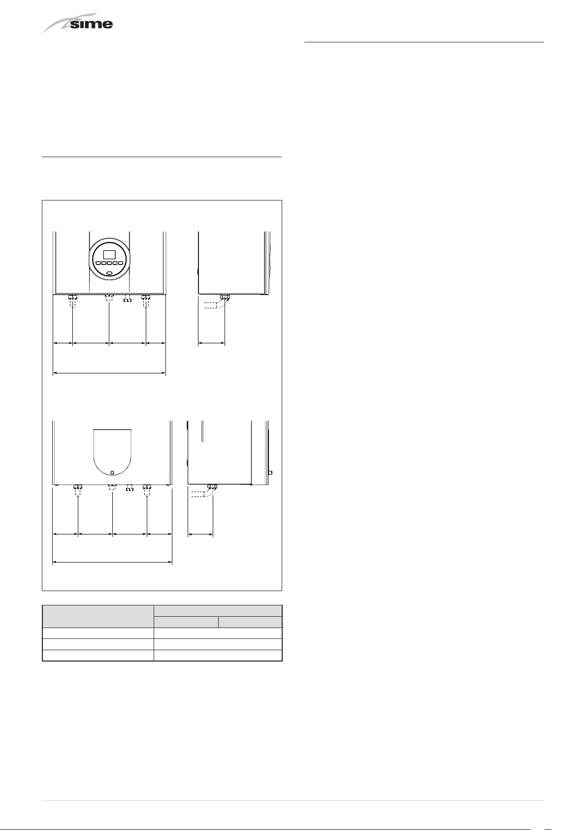
8.9 Plumbing connections
The plumbing connections have the following characteristics
and dimensions.
Brava Slim 30 BFRi
8.10 Gas supply
Brava Slim 30 BFR
NATURAL GAS
gas
without the need for any type of mechanical conversion. Select
parameter
the type of gas to be used.
If changing the type of gas to be used, carry out the entire
appliance
Boiler connection to the gas mains must be carried out in full
compliance with installation Standards in force.
Before connecting the boiler to the gas mains, the user must
ensure that:
– the type of gas is correct for the appliance
– the pipes are clean
– the gas supply pipe is the same dimension as or greater than
that of the boiler fitting (G3/4") and with a load loss less than
or equal to that contemplated between the gas mains and the
boiler.
"03"
"COMMISSIONING"
boilers leave the factory prearranged for
and can also work with
(see “Parameter setting and display") and set
phase.
Universal LPG
M G R
400
Brava Slim 30 BFRe
130 130 ==
M G R
450
a
m
130130 ==
95
Fig. 21
97
WARNING
Once installation has been completed, check that
the joints are air tight as indicated in the installation
Standards.
CAUTION
It is recommended that the gas line has a suitable
filter.
Description
M - System delivery Ø 3/4" G
R - System return Ø 3/4" G
G - Gas supply (*) Ø 3/4" G
(*) Brass adaptor for gas connection supplied. G3/4" to R3/4".
24
Brava Slim BFR
30 BFRi 30 BFRe
Fig. 22
8.11 Connecting the flue
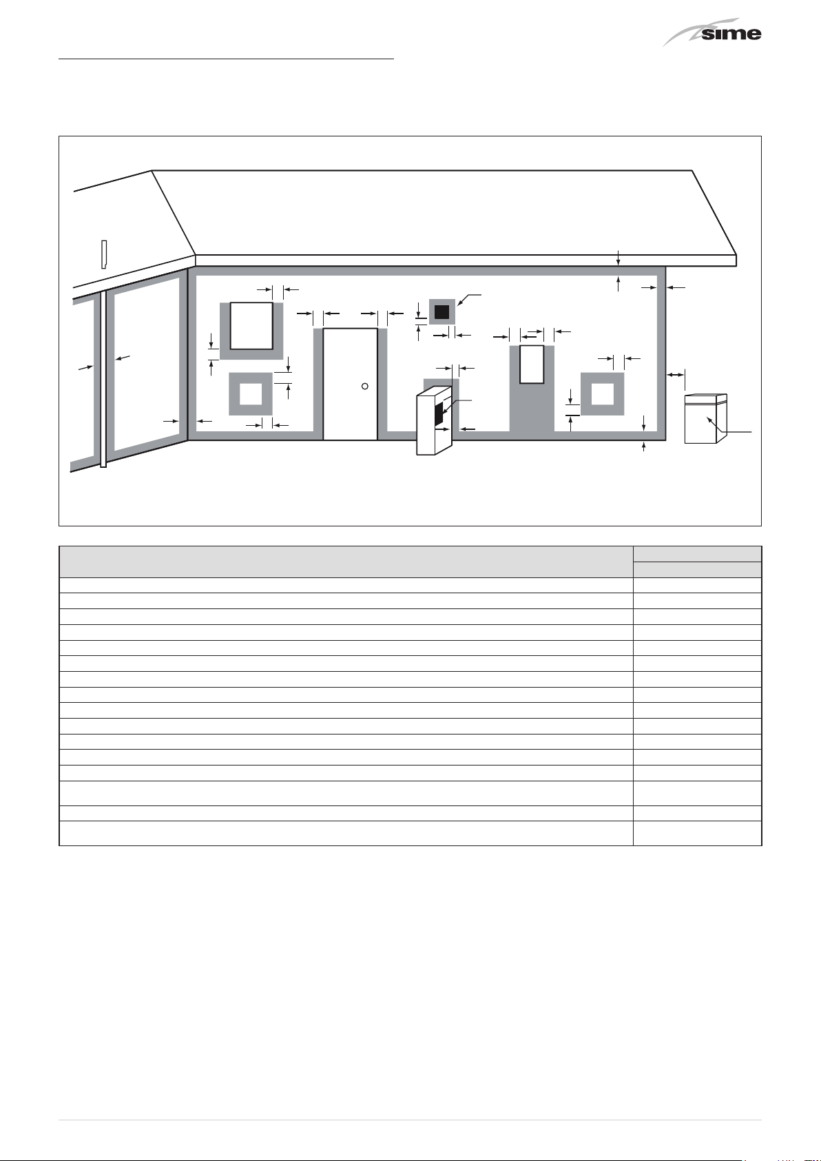
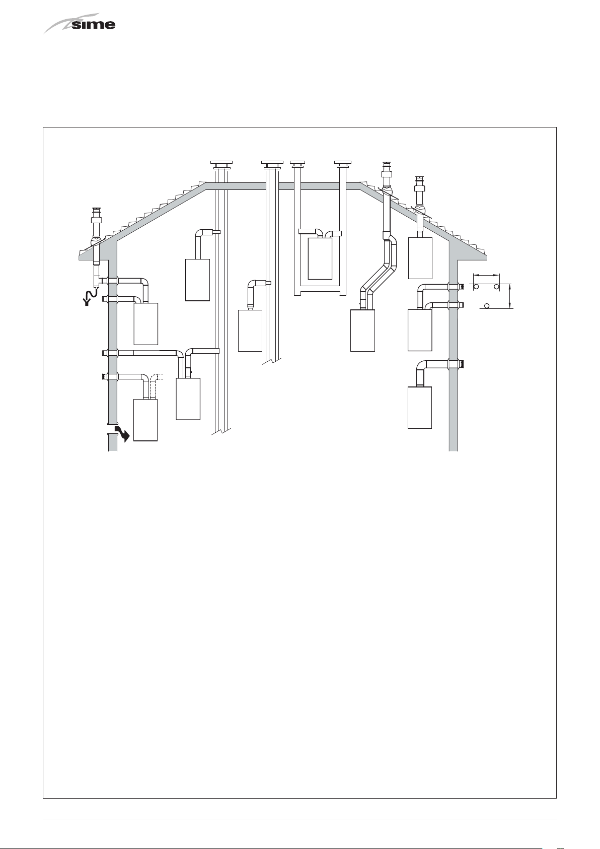
8.11.1 Flue Terminal Positions
a
j
w
f
DESCRIPTION
Flue terminal T
Mechanical air inlet I
Gas meter M
Electricity meter of fuse box P
Shaded area indicates prohibited area
Below eaves, balconies and other projections (Appliances over 50MJ/h) a 300
From the ground, above a balcony or other surface b 300
From a return wall or external corner c 300
From a gas meter d 1000
From an electricity meter or fusebox/breaker panel e 500
From a drain pipe or soil pipe f 75
Horizontally from any building structure or obstruction facing a flue terminal g 500
From any other flue terminal, cowl or combustion air intake h 300
Horizontally from any opening window, door, non-mechanical air inlet or other opening into a building
with the exception of sub-floor ventilation
From a mechanical air inlet including a spa blower. k 1000
Vertically below an opening window, non-mechanical air inlet or any other opening into a building with
the exception of sub-floor ventilation
n
I
c
k
j j
Door
k
h
T
h
h
T
g
e
e
P
d
d
M
j 300
n 500
c
g
b
Brava Slim 30 BFR
Min. Clearance (mm)
T
Fig. 23
m
m
CAUTION
–
Use as a guide only. See AS/NZS5601 for flue design
details.
–
Refer to AS/NZS5601, current version, or local gas
fitting rules for specific locations.
CAUTION
– The location of the flue terminal must comply with
the clearances shown on this page. If you are unsure
about clearances not indicated here, in general refer
to AS/NZS 5601, or your local authority.
m
CAUTION
– All measurements are the minimum clearances
required.
– Terminals must be positioned so to avoid combustion
products entering the building.
– When the installer installs the flue through a
wall, the wall must be adequately sealed and the
hole must not affect the building structure or fire
resistance.
– Install a fire proof back board if installing on
combustible surfaces.
– The fixing method and the wall structure must be
sufficient to hold the weight of the boiler.
25
8.11.2 Installation of coaxial flues 60/100mm – 80/125mm
max 0,5 m
Coaxial flue kits that are supplied separately. The diagrams below, illustrate some examples of fluing options allowed and the
maximum lengths than can be achieved. It is essential that a flue gas analysis point is made available directly above the boiler.
8.11.3
Brava Slim 30 BFRi
Permitted outlets
C52
C52X
B22P
B52P
B32P
C82
C82X
C42
C42X
C42
C42X
C32
C32X
C32
C32X
C12
C12X
C12
C12X
max 0,5 m
B22P-B52-B52P
Combustion air inlet into the atmosphere and smoke
outlet to open air.
NOTE:
opening for combustion air (6 cm2 x kW).
C12-C12X
Concentric wall smoke outlet The pipes can start from
the boiler but the outlets must be concentric or close
together (no more than 50 cm) to be subject to similar
wind conditions.
C32-C32X
Concentric roof outlet Outlet as C12X.
C42-C42X
Outlet and inlet in shared or separate flue pipes but
subjected to similar wind conditions.
C52-C52X
Separate wall or roof inlet and outlet in different
pressure areas.
NOTE:
the inlet and outlet must never be positioned on
opposing walls.
C82-C82X
Outlet in single or shared flue or with inlet on wall.
P:
smoke outlet system designed to operate with
positive pressure.
X:
appliances and corresponding smoke outlet which
meet German air-tightness requirements.
Fig. 24
26

m
WARNINGS
– The smoke flue and the connection to the flue pipe
must be in compliance with the national and local
Standards and Legislation in force.
– The use of rigid ducts which are resistant to
temperature, condensate, mechanical stress and
are air-tight is compulsory.
– Outlet ducts which are not isolated are a risk of
danger.
8.11.4 Coaxial duct (Ø 60/100mm and Ø 80/125mm)
Coaxial accessories
Load loss - Equivalent lengths
Description
Coaxial duct kit 8084813 8084830
Extension W. 1000 mm 8096103 8096130
Extension W. 500 mm 8096102 -
Vertical extension W. 200 mm
with smoke analysis take-off
point
Adapter for Ø 80/125 mm - 8093120
Additional 90° curve 8095801 8095820
Additional 45° curve 8095900 8095920
Roof outlet terminal W. 1284
mm
Vertical condensation recovery
W. 200 mm
Model
90° curve 1 1
45° curve 0.5 0.8
Ø 60/100 mm Ø 80/125 mm
8086908 -
8091200 8091200
8092803 8092803
Ø 60/100 mm Ø 80/125 mm
Code
Leq (linear metres)
1
Fig. 25
When the outlets are
Type C12
or
C42
the diaphragm is to be
removed or kept following the indications below:
Model Diaphragm for duct L
Brava Slim 30 BFRi
When the outlet is
Type C32
YES
(leave mounted)
NO
(remove it)
(vertically straight without any
< 1 m
> 1 m
curves), the presence of the diaphragm modifies the maximum
length of the duct as shown below:
Model Diaphragm Max L (m)
Brava Slim 30 BFRi
YES 2.5
NO 5
Minimum-Maximum Lengths
Model
Brava Slim 30 BFRi
m
CAUTION
(*) Vertical condensate recovery MUST be introduced
Duct Length Ø
60/100
W
Horizontal
(m)
Min.
Max.
- 3.0
H
Vertical
(m)
Min.
1.3
(*)
Max.
Duct Length Ø
80/125
W
Horizontal
(m)
Min.
Max.
5 3 6 4 7
H
Vertical
(m)
Min.
Max.
for vertical ducts (Type C32) or vertical sections of the
duct (Type C42) longer than 1.3m.
Diaphragms for coaxial ducts
Boilers leave the factory equipped with a diaphragm (1) with the
following characteristics:
Brava Slim 30 BFRi
–
: diaphragm Ø 81 mm.
27

8.11.5
450
OFF
1
The boiler
coaxial ducts for smoke outlet and combustion air inlet.
Brava Slim 30 BFRe
Brava Slim 30 BFRe
1
5
is supplied already complete with
2
3
4
8.12 Electrical connections
The boiler is equipped with a ready wired power cable which is
to be connected to a 230V~50 Hz network.
If this cable needs to be replaced, an original spare must be
Sime
requested from
Therefore only the connections of the original components
as shown in the table are needed. These are to be ordered
separately from the boiler.
DESCRIPTION CODE
External sensor kit (ß=3435, NTC 10KOhm at 25°C) 8094101
Remote control HOME (open therm) 8092280
Remote control HOME PLUS (open therm) 8092281
.
KEY:
1
90° coaxial bend
2
Coaxial duct (supplied, but not fitted)
3
Air inlet
4
Smoke outlet
5
Take-off point for smoke analysis
220
125
Fig. 26
m
a
To facilitate introduction of the connection wires of the optional
components into the boiler:
– disassemble the smoke outlet duct of the
– remove the screws (1), pull the front panel (2) forwards and
CAUTION
The maintenance interventions described must ONLY
be carried out the professionally qualified personnel.
WARNING
Before carrying out any interventions described:
– set the main system switch to "OFF"
– close the gas valve
– make sure that no hot parts inside the appliance are
touched.
Fig. 28
Brava Slim 30 BFRe
release it from the top by lifting it
2
140
28
Ø 60/100
Fig. 27
Fig. 29
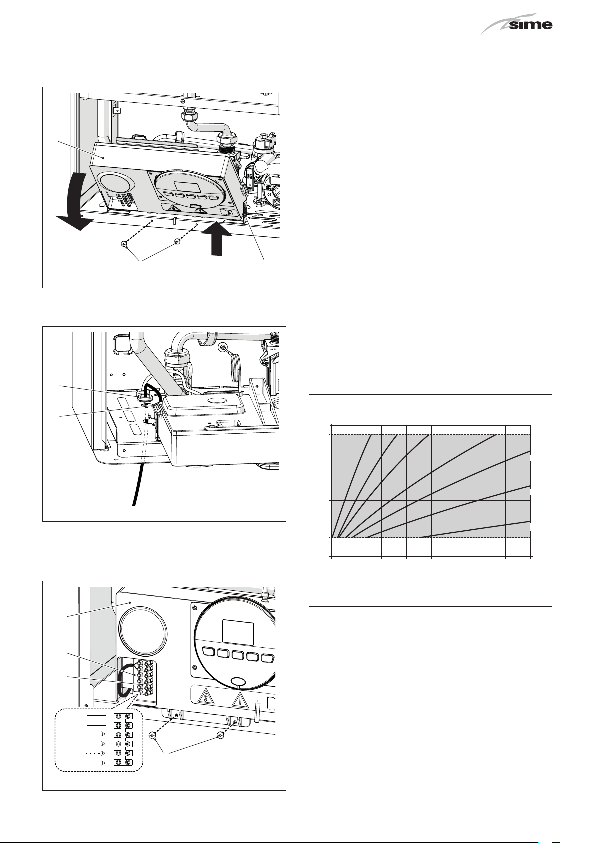
– remove the screws (3) securing the control panel (4)
20 15 10 5 0 -10 -15-5 -20
°C
– move the panel (4) upwards (a) but keeping it in the side
guides (5) to the end of travel
– bring it forwards and down (b) until it is horizontal
4
m
CAUTION
It is compulsory:
– to use an omnipolar cut-off switch, disconnect
switch in compliance with AS/NZS Standards
– if the power cable is to be replaced, that ONLY
a special cable is used with a factory produced
re-wired connector, ordered as a spare part and
connected by a professionally qualified person
– to connect the earth wire to an effective earthing
system (*)
– that before any intervention on the boiler, the mains
power is disconnected by setting the main system
switch to "OFF".
b
a
3
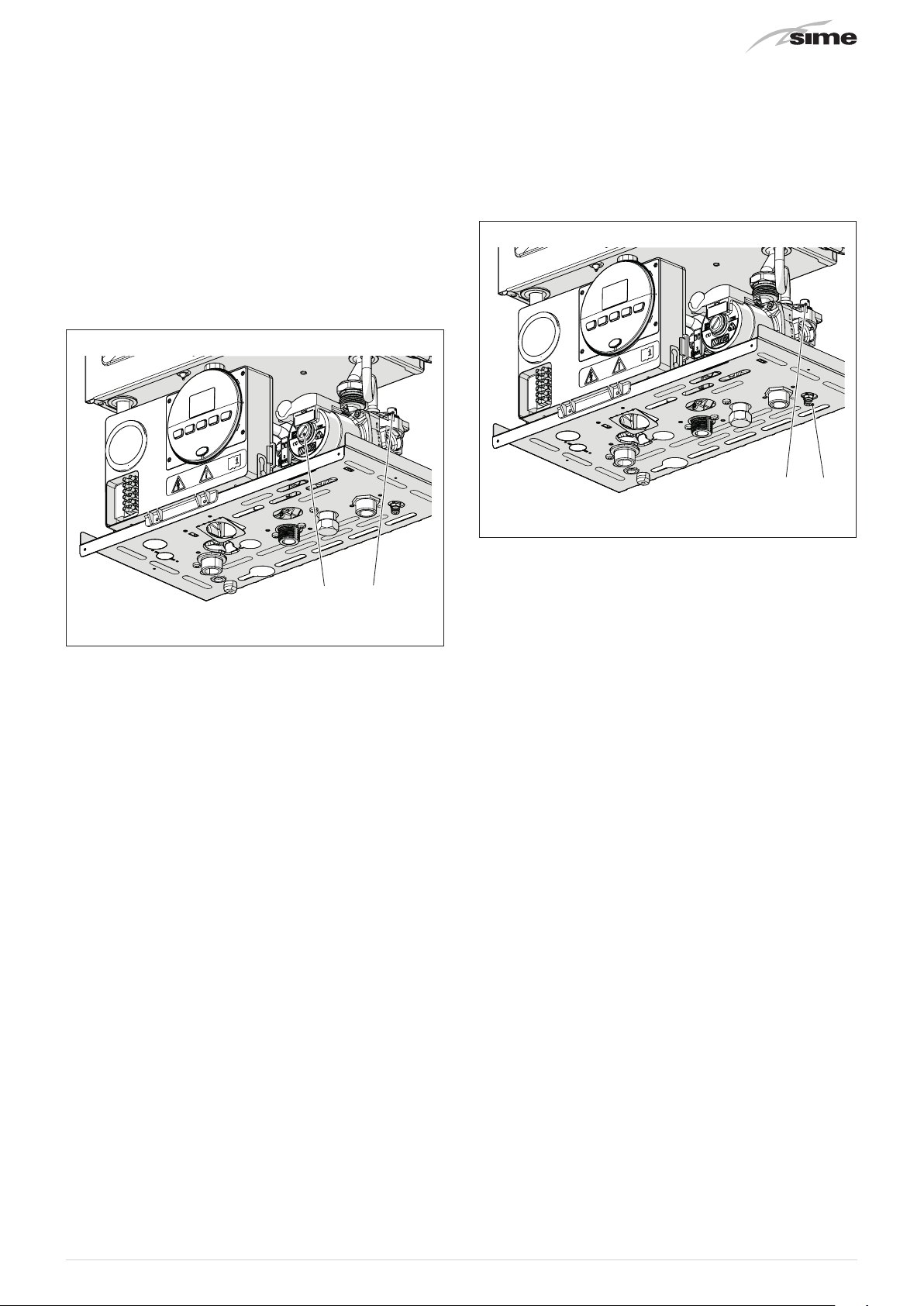
– insert the connection wires into the cable gland (6) and the
opening (7) on the control panel
6
7
– bring the control panel (4) to the original position and secure
it with the screws (3) which were removed previously
– connect the component wires to the terminal board (8)
following the indications provided on the data plate (9).
5
Fig. 30
Fig. 31
(*) The manufacturer is not responsible for any damage
caused by failure to earth the appliance or failure to
observe the information provided in the wiring diagrams.
d
IT IS FORBIDDEN
To use water pipes for earthing the appliance.
8.12.1 External sensor
The boiler is prearranged for connection to an external air
temperature sensor and can operate with a sliding temperature.
This means that the delivery temperature sent to the boiler can
vary on the basis of the external temperature depending on the
climatic curve selected from those shown in the diagram (Fig.
33).
When fitting the sensor on the outside of the building, follow
the instructions provided on the packaging of the product itself.
Climatic curve
Delivery temperature
90
80
70
60
50
40
30
20
K=9 K=6 K=4.5 K=3
K=2.2
K=1.5
K=0.75
°C
External temperature
4
9
8
CR-TA
SE
SAUX
6
5
4
3
2
1
3
Fig. 32
m
Fig. 33
CAUTION
If there is an external sensor, in order to select the
optimal climatic curve for the system and therefore
the delivery temperature based on the external
temperature:
– press the button
– press buttons
been selected (within the range
for 1 second
t
or < until the required curve K has
>
K=0.0 - K=9.0
).
29

8.12.2 Chrono-thermostat or Air Thermostat
CR
SE
SE
The electrical connection of the chrono-thermostat or air
thermostat has already been described. When fitting the
component in the room where the readings are to be taken,
follow the instructions provided with the device.
MULTI ZONE system - with pump, air thermostat and external
sensor.
TA1
TA2
TA3
8.12.3 EXAMPLE of use of the command/control device
on some types of heating systems
KEY
M System delivery
R System return
CR Remote control
SE External sensor
TA÷TA3 Air thermostat for the zone
VZ1-VZ3 Zone valves
RL1-RL3 Zone relays
P1-P3 Zone pump
SP Hydraulic separator
ONE DIRECT ZONE system , external sensor and air thermostat.
SE
M
R
TA
TA
M
R
SP
RL1
RL2 RL3
P2P1
P3
Fig. 36
8.13 Refilling or emptying
Before carrying out the operations described below, make
sure that the main system switch is set to "ON" in order for the
display to show the pressure level in the system during refilling.
Make sure that the operating mode is set to "Stand-by";
the case, press the button
mode has been selected.
ON
for at least 1 second until this
y
if this is not
Fig. 34
MULTI ZONE system - with zone valve, air thermostat and
external sensor.
TA
M
m
TA1
R
VZ1 VZ2 VZ3
CAUTION
Set the parameter "tS 17 = DELAY SYSTEM PUMP
ACTIVATION to allow the opening of zone valve Vz.
TA2 TA3
Fig. 35
Fig. 37
8.13.1 REFILL operations
Remove the front panel:
– disassemble the smoke outlet duct of the
– remove the two screws (1), pull the front panel (2) forwards
and release it from the top by lifting it.
2
1
Brava Slim 30 BFRe
Fig. 38
30
Heating circuit:
– open the isolation and air bleeding valves in the highest points
of the system
– loosen the automatic bleed valve (3)
– open the isolation valves of the heating circuit (if present)
– Open the filling valve, which should be on the system return
– Fill until the water overflows from the air bleeding valves and
shut off the valves again
1-1.2
– Continue filling until the pressure reaches
bar (100-120
kPa) as shown on the display
– close the filling valve
– check that there is no air in the system by bleeding all the
radiators and the circuit on the high points of the system
– remove the front plug (6) of the pump and use a screwdriver
to check that the impeller is not blocked
– replace the plug (6)
8.13.2 EMPTYING operations
Boiler:
– loosen the automatic bleed valve (3)
– close the heating circuit isolation valves
– check that the filling valve is closed
– connect a rubber hose to the boiler drain valve (7) and open it
– when it has fully emptied, close the drain valve (7)
– close the automatic bleed valve (3).
73
Fig. 40
6 3
Fig. 39
NOTE:
to completely remove all air from the system, it is
recommended that this operation is repeated a number of times.
– check the pressure on the display and if necessary top up until
the correct pressure reading appears
– close the automatic bleed valve (3).
Refit the front panel of the boiler hooking it on at the top,
pushing it forwards and securing it with the screw (1) which was
removed previously.
Fit the smoke outlet duct of the
Brava Slim 30 BFRe
.
31

9 COMMISSIONING
9.1 Preliminary operations
Before commissioning the appliance, check that:
– the type of gas is correct for the appliance
– the gas isolation valves for the heating system and the water
system are open
– the pump impeller rotates freely.
9.2 Before commissioning
After having carried out the preliminary operations, perform the
following to start the boiler:
– set the main system switch to "ON"
ON
Fig. 41
"ALL"
– if there is a fault, the message
"06"
display, the fault code (eg.
message
m
– adjust the air thermostat and check that the boiler starts and
operates correctly
– to check that the pressure in the network and the nozzles are
correct, the procedure described in section must be carried
out "Chimney sweeper function".
d
CAUTION
To restore the start conditions press and hold the
button
can be carried out no more than 6 times.
.
for more than 3 seconds. This operation
y
- no flame detected) and the
will appear on the
– the type of gas for which the boiler has been calibrated,
"LG"
(methane) or
the power. After this the correct representation of the symbols
will be checked and finally
– check that the system pressure as shown on the pressure
gauge when the system is cold , is between
and 120 kPa)
– press the button y twice to select "WINTER mode" n.
the value of the delivery sensor detected at that moment will
appear on the display
(UNIVERSAL LPG) will appear followed by
"- -"
will appear on the display
1 and 1.2 bar (100
"nG"
– adjust the air thermostat and check that the boiler starts and
operates correctly
– the boiler will remain in operation while any heat request is
active
32

9.3 Parameter setting and display
To go into the parameter menu:
– from the selected mode (eg. WINTER)
– once the required parameter has been reached, press the
buttons
or <to modify the value within the permitted range.
>
The modifications are stored automatically.
– press the buttons ( and t (for approximately 5 seconds)
at the same time until
"PAR 01"
(parameter number) and the
value set (0-4) appears on the display
– press the button t to scroll up the list of parameters and
then
NOTE:
to scroll down the list
(
holding the buttons ( or t increases the speed of the
When all the parameter modifications have been made, exit the
parameter menu by pressing and holding down the buttons
at the same time
and
t
NOTE:
In case of power failure all settings are stored.
until the initial screen is displayed.
scrolling movement.
9.4 List of parameters
Type No. Description Range U/M Step Default
CONFIGURATION
PAR 01
PAR 02
PAR 03
PAR 04
PAR 08 External sensor value correction -5 .. +5 °C 1 0
PAR 10 Boiler Antifreeze Threshold 0 .. +10 °C 1 3
PAR 11
PAR 12 Heating Curve Incline 0 .. 80 - 1 20
PAR 13 Minimum Heating Temperature Adjustment 20 .. PAR 14 °C 1 20
PAR 14 Maximum Heating Temperature Adjustment PAR 13 .. 80 °C 1 80
PAR 15 Maximum power heating 0 .. 100 % 1 100
PAR 16 Heating Post-Circulation Time 0 .. 99
PAR 17 Heating Pump Activation Delay 0 .. 60
PAR 18 Re-ignition Delay 0 .. 60 Min 1 3
PAR 19 - - - - PAR 20 - - - - PAR 21 Minimum heating power 0 .. 100 % 1 0
PAR 22
PAR 23
Index showing boiler power in kW
0 = 24; 1 = 30; 5 = AUS
Hydraulic configuration
0 = rapid
1 = storage tank with thermostat or heating only
2 = hot water tank with sensor
3 = bithermic
4=instant with solar power input
Gas Type Configuration
0 = NATURAL GAS; 1 = UNIVERSAL LPG
Combustion configuration
0 = sealed chamber with combustion control
1 = open chamber with smoke thermostat
2 = Low NOx
DOMESTIC HOT WATER - HEATING
External Sensor Antifreeze Threshold
-- = Disabled
Domestic hot water preheating enabling
0 = OFF; 1 = ON
External relay 1 function
0 = not used; 1 = remote alarm NO; 2 = remote alarm NC; 3 = zone
valve; 4 = automatic filling; 5 = external request; 6 = recirculation
pump; 7 = zone valve with OT; 8 = relaunch pump
0, 1 or 5 - 1 5
0 .. 4 - 1 1
0 .. 1 - 1 0 or 1
0 .. 2 - 1 0
-9 .. +5 °C 1 -2
seconds
x 10
seconds
x 10
0 .. 1 - 1 0
0 .. 8 - - 0
1 3
1 0
(
33

Type No. Description Range U/M Step Default
OFF
External relay 2 function
PAR 24
PAR 25
PAR 26 Zone Valve / Pump Relaunch Delay 0 .. 99 Min 1 1
PAR 28 - - - - PAR 29 - - - - PAR 30 - - - - -
PAR 35
PAR 40 Modulating Pump Speed
PAR 41 ∆T Modulating pump delivery/Return 10 .. 40 °C 1 20
PAR 47
PAR 48 INST Parameter set to default 0 .. 1 - - 0
0 = not used; 1 = remote alarm NO; 2 = remote alarm NC; 3 = zone
valve; 4 = automatic filling; 5 = external request; 6 = recirculation
pump; 7 = zone valve with OT; 8 = relaunch pump
Auxiliary TA function
0 = according to TA
1 = TA Antifreeze
2= domestic hot water disabled
Digital / analogue Pressure switch
0 = water pressure switch
1 = water pressure transducer
2 = water pressure transducer (only pressure displayed)
System pump forcing (only in winter mode)
0 = Disabled
1 = Enabled
RESET
0 .. 8 - - 0
0 .. 2 - 1 0
0 .. 2 - 1 1
-- = No modulation
AU = Automatic 30
.. 100
0 .. 1 - 1 0
% 10 AU
In the event of a fault/malfunction the message
"ALL"
appear on the display with the alarm number eg.
(Domestic Hot Water Sensor Fault).
Before repairing the fault:
– disconnect the appliance from the mains power by setting the
main switch to "OFF"
– as a precautionary measure, close the gas isolation valve.
Repair the fault and start-up the boiler again.
NOTE:
after having repaired the fault, when the alarm number
appears on the display together with the message
(see figure), press the button
for approximately 3 seconds
y
to start the appliance up again.
34
will
"ALL 04"
Fig. 42
d
9.5 Fault / malfunction codes
Type No. Description
ALL 02 Low water pressure in system
ALL 03 High water pressure in system
ALL 05 Delivery sensor fault
ALL 06 No flame detection
ALL 07 Dual sensor intervention
ALL 08 Fault in the flame detection circuit
ALL 09 No water circulating in the system
ALL 10 Auxiliary sensor fault
ALL 11 Gas valve modulator disconnected
ALL 12 Incorrect configuration of the open /sealed chamber
ALL 17
ALL 28 Maximum number of consecutive releases
ALL 37 Fault due to low network voltage
ALL 40 Incorrect network frequency detected
ALL 41 Flame loss more than 6 consecutive times
ALL 42 Button fault
ALL 43 Open Therm communication fault
ALL 44 Anomaly inside electronic board
ALL 62 The self-calibrating procedure must be carried out
ALL 72 Incorrect positioning of the delivery sensor
ALL 74 Fault in the 2nd element of the delivery sensor
ALL 80 Anomaly in gas valve control line
ALL 81 Block due combustion during start-up
ALL 83 Irregular combustion (temporary error)
ALL 88 Anomaly inside electronic board
ALL 96 Block due to clogging in smoke outlet
Fault regarding maximum deviation between the 2
NTC heating sensors

9.6 Display of operating data and counters
Once the boiler is operating a qualified technician can view the
operating data and the counters as follows:
– from the operating screen in the "WINTER" mode
– go into
same time
"DISPLAY"
by pressing the buttons ( and <
for more than 3 seconds until the following screen
appears
From this point, the technician has 2 options:
– scroll through the list of
(PARc)"
by pressing the button t. Scrolling will be in sequence
– display the
the button
“activated alarms”
(
"information (PAR)"
(no more than 10) by pressing
and
n
at the
"counters
TABLE OF INFORMATION DISPLAYED
Type No. Description
PAR 00 SW version
PAR 01 External sensor
PAR 02
PAR 03
PAR 04
PAR 05
PAR 06
PAR 08
PAR 09
Delivery sensor 1
temperature
Delivery sensor 2
temperature
Actual heating SET
temperature
Water pressure
transducer reading
(if resent)
0…99 bar 0.1
TABLE OF COUNTER DISPLAYED
Type No. Description
PAR c0
PAR c1
PAR c2
PAR c3 total no. faults
PAR c4
PAR c5
PAR c6
total no. of boiler
operating hours
total no. of burner
operating hours
total no. of burner
ignitions
total no. of times
installer parameters
"ALL"accessed
total no. of times
OEM parameters
accessed
time unitl next
maintenance
intervention
Range
- 9 ..
99
- 9 ..
99
- 9 ..
99
Pa r.
13 …
Pa r.
14
Range
0 ..
99
0 ..
99
0 ..
99
0 ..
99
0 ..
99
0 ..
99
1 ..
199
U/M Step
°C 1
°C 1
°C 1
°C 1
U/M Step
0.1; from
h x 1000
h x 1000
h x 1000
months 1
0.0 to 9.9;
1; from 10
to 99
0.1; from
0.0 to 9.9;
1; from 10
to 99
0.1; from
0.0 to 9.9;
1; from 10
to 99
x 1 1
x 1 1
x 1 1
– Once in this section, proceed with button t or (.
When all the values have been displayed, exit the menu by
pressing and holding down the button yfor approximately 5
seconds until the initial screen is displayed.
TABLE OF ACTIVATED ALARMS/FAULTS
Type No. Description
PAR A0 Last activated alarm/fault
PAR A1 Last but one activated alarm/fault
PAR A2 Third from last activated alarm/fault
PAR A3 Previous activated alarm/fault
PAR A4 Previous activated alarm/fault
PAR A5 Previous activated alarm/fault
PAR A6 Previous activated alarm/fault
PAR A7 Previous activated alarm/fault
PAR A8 Previous activated alarm/fault
PAR A9 Previous activated alarm/fault
35
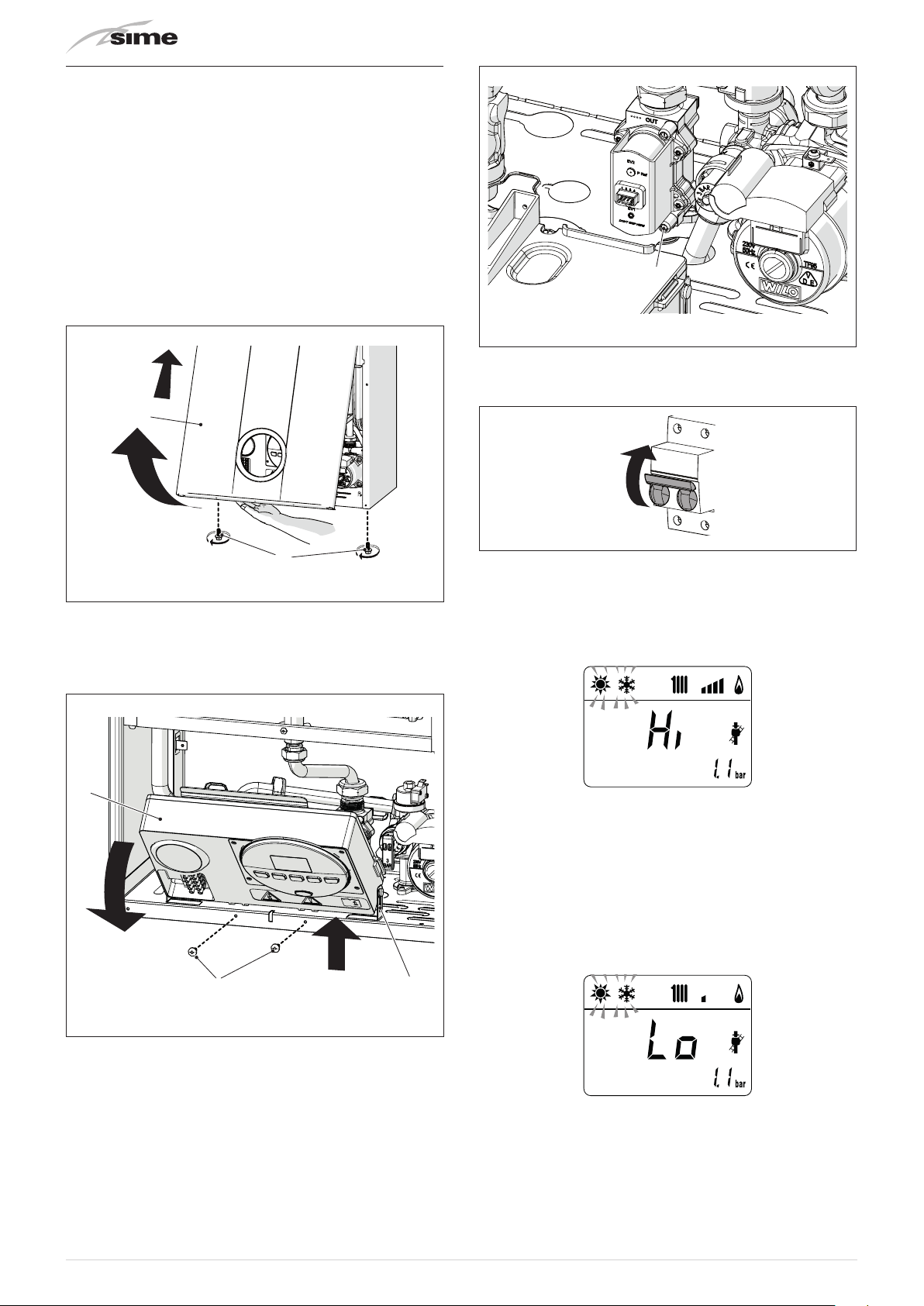
9.7 Checks after commissioning
9.7.1 Chimney sweeper function
The chimney sweeper function is used by the qualified
maintenance technician to check the mains gas pressure, detect
the combustion parameters and to measure the combustion
efficiency required by legislation in force.
This function lasts 15 minutes and is activated by proceeding
as follows:
– disassemble the smoke outlet duct of the
if not already removed
– if the panel (2) has not already been removed, remove the
two screws (1), pull the front panel (2) forwards and release it
from the top by lifting it
2
Brava Slim 30 BFRe
,
6
Fig. 45
– open the gas valve
– power the boiler by setting the main switch to "ON"
ON
1
Fig. 43
– remove the screws (3) securing the control panel (4)
– move the panel (4) upwards (a) but keeping it in the side
guides (5) to the end of travel
– bring it forwards and down (b) until it is horizontal
4
b
a
3
5
Fig. 46
– press the button y for at least 1 second until "SUMMER"
mode
– press and hold down the buttons
for approximately 10 seconds until the message “Hi” appears
on the display together with the flashing symbols
– press the button > to make the boiler operate at maximum
power
pressure gauges correspond to those indicated in the table
below
– press the button
power "Lo" and check that the gas pressure values on the
pressure gauges correspond to those indicated in the table
below. The message “Lo” will appear on the display together
with the flashing symbols
has been selected
l
and > at the same time
<
l
"Hi"
and check that the gas pressure values on the
to make the boiler operate at minimum
<
and
l
n
and
n
– close the gas valve
– loosen the screw of the "mains pressure" point (6) and connect
a pressure gauge
36
Fig. 44
– press the button > once again to make the boiler operate at
maximum power. If the gas pressure values are correct it is
possible to determine the combustion data and take a reading
of the combustion efficiency as provided for by legislation in
force
– press the button
Procedure”. The boiler water delivery temperature will
appear on the display
– disconnect the pressure gauge, carefully close the pressure
point (6), put the control panel back to the original position
and refit the front panel (2).
Gas supply pressure
Type of gas NATURAL GAS UNIVERSAL LPG
Pressure (mbar/kPa) 11.3/1.13 27.5/2.75
Installation with SPLIT PIPE SYSTEM smoke outlet
Model Heat Output
Brava Slim 30
BFRi
Installation with CONCENTRIC smoke outlet
Model Heat Output
Brava Slim 30
BFRi
Brava Slim 30
BFRe
If the gas pressure values are different from the values indicated
in the table, adjust the gas nozzle pressure as described in the
section below.
to exit the "Chimney sweeper
y
Pressure at nozzles (mbar/kPa)
UNIVERSAL
20.2 - 20.6
2.02 - 2.06
4.3 - 4.6
0.43 - 0.46
UNIVERSAL
20.5 - 21.0
2.05 - 2.10
4.5 - 5.0
0.45 - 0.50
20.5 - 21.0
2.05 - 2.10
4.5 - 50
0.45 - 0.50
Max
min
Max
min
Max
min
NATURAL GAS
5.3 - 5.6
0.53 - 0.56
0.8 - 1.1
0.08 - 0.11
Pressure at nozzles (mbar/kPa)
NATURAL GAS
5.8 - 6.2
0.58 - 0.62
1.3 - 1.6
0.13 - 0.16
5.8 - 6.2
0.58 - 0.62
1.3 - 1.6
0.13 - 0.16
LPG
LPG
9.7.2 Adjusting gas pressure at the nozzles
m
CAUTION
Considering that:
– the front panel (2) has already been removed and
the point (6) is connected to the pressure gauge
– the main system switch must be set to "ON"
– the gas supply must be open
– the heat requests must be active ("Winter" mode
with TA closed)
the adjustments described below must be carried out
–
in sequence.
n
Adjusting maximum gas pressure:
– press button
the button
– set the room thermostats to the maximum temperature
– press and hold down the buttons
for approximately 6 seconds until the message "MA" appears
on the display alternating with "nu"
–
open one or more than one hot water tap
– the boiler will start up and the message "P01" will appear on
the display (Adjusting maximum gas pressure)
– press the buttons > or < until the pressure value indicated in
the table appears on the pressure gauge
– once the value indicated in the table has been reached, press
the button
value which will then flash once.
Adjusting minimum gas pressure:
– press the button
the display
– press the buttons > or < until the pressure value indicated in
the table appears on the pressure gauge
– once the value indicated in the table has been reached, press
the button
value which will then flash once.
– press and hold down the buttons
time for approximately 6 seconds until the water delivery
temperature appears on the display and the boiler shuts
down/starts up
– close the valves which were opened previously.
and set the HEATING SET to maximum using
)
>
and y at the same time
>
for approximately 2 seconds to confirm the
y
twice, the message "P00" will appear on
(
for approximately 2 seconds to confirm the
y
and y at the same
>
37

9.8 Gas conversion
OFF
1
3
4
Brava Slim 30 BFR
NATURAL GAS to operation with UNIVERSAL LPG by installing
the "Nozzle kit for G30/G31", code 5144716 to be ordered
separately from the boiler.
models can be converted from operation with
m
a
CAUTION
The maintenance interventions described must ONLY
be carried out the professionally qualified personnel.
WARNING
Before carrying out any interventions described:
– set the main system switch to "OFF"
– close the gas valve
– make sure that no hot parts inside the appliance are
touched.
Fig. 47
9.8.1 Preliminary operations
To carry out the conversion:
– disassemble the smoke outlet duct of the
– remove the screws (1), pull the front panel (2) forwards and
release it from the top by lifting it
Brava Slim 30 BFRe
Fig. 49
– remove the four screws (3) and remove the front panel (4)
from the combustion chamber (6) working carefully so as not
to damage the gasket or the panel insulation
5 6
2
– remove the screw (7) and extract the electrode (8)
– remove the swivel joint (9) and the counter-nut (10)
– remove the screws (11)
– remove the gas manifold (12), replace the nozzles fitted in the
factory with the nozzles supplied with the accessory kit and
position the gaskets
12
Fig. 48
– remove the four screws (3) and remove the front panel (4)
from the sealed chamber
11
7
8
– refit the gas manifold (12) securing it with the screws (11)
10
9
Fig. 50
Fig. 51
38

– tighten the counter-nut (10) and the swivel joint (9) and
3
4
1
position the gasket
– refit the electrode (8) putting its end
burner element (*)
– check that the gasket and the insulation of the front panel (6)
of the combustion chamber and the gasket (13) of the front
panel (4)of the sealed chamber are all integral. If they are not,
replace them
– refit the panels (6) and (4) securing them with fastening
screws
m
CAUTION (*)
The position of the electrode is essential for the correct
detection of current ionization.
13
IN THE MIDDLE
of the
9.9 Automatic calibration procedure
m
CAUTION
This procedure and the procedures relating to "
conversion
gas
– replacing the nozzles for the gas conversion
– changing the gas valve following a fault
– changing the electronic board following a fault.
Considering that:
– the front panel has been removed, the control
panel has been brought forward and down and that
the points (6) and (7) of the gas valve have been
connected to the pressure gauges
– the main system switch must be set to "ON"
– the gas supply must be open
– no heat requests must be active ("Winter" mode
with TA open)
the adjustments described below must be carried out
–
in sequence.
", "
Adjusting max gas
",
MUST BE CARRIED OUT
6
" and "
after:
Gas
Adjusting min
n
Fig. 52
– apply the label indicating the new gas configuration on the
technical plate (14) on the inside of the front panel
– carry out the "Automatic calibration procedure" and then
refit the front panel (2) securing it with the two screws (1).
2
14
7
Fig. 54
Procedure valid for GAS CONVERSION
– go into the parameter section by pressing the buttons
(for approximately 5 seconds) at the same time until
t
01"
(parameter number) and the value set (0-4) flashes on the
display
NOTE:
holding the buttons ( or t increases the speed of the
scrolling movement. Pressing the button
scroll through the previous parameters.
– keep the button t pressed and scroll through the parameters
until reaching parameter "03"
allows the user to
(
(
and
"PAR
Fig. 53
39

– press the button > and select "1" (UNIVERSAL LPG)
– go into the parameter section (if not already there) by pressing
the buttons
same time until
set (0-4) flashes on the display
– keep the button
until reaching parameter
and t (for approximately 5 seconds) at the
(
"PAR 01"
t
(parameter number) and the value
pressed and scroll through the parameters
"PAR 49"
– exit the parameter section by pressing and holding down the
and t
buttons
until the delivery temperature is displayed.
m
Adjusting maximum gas pressure:
– press the button
selected
– press button
maximum using the button
– press and hold down the buttons > and y at the same time
for approximately 6 seconds until the message
on the display alternating with
(
IMPORTANT
To complete this task the user
following procedure.
at the same time
until "WINTER" mode nhas been
y
and set the DOMESTIC HOT WATER SET to
(
(approximately 5 seconds)
MUST
>
"to"
carry out the
"Au"
appears
– press and hold the button > to set the value
– the modified value will be stored automatically
– keep the button
until reaching parameter
– press the button > to set the value
– the modified value will be stored automatically
pressed and scroll through the parameters
t
"PAR 70"
at "5"
at "49"
– the boiler will start up and the message
the display (Adjusting maximum gas pressure)
– press the buttons > or < until the pressure value indicated in
the table appears on the pressure gauge
– once the value indicated in the table has been reached, press
the button
value which will then flash once.
Adjusting minimum gas pressure:
– press the button
the display
for approximately 2 seconds to confirm the
y
twice, the message
(
"P01"
will appear on
"P00"
will appear on
– press the buttons > or < until the pressure value indicated in
the table appears on the pressure gauge
– once the value indicated in the table has been reached, press
the button
value which will then flash once
40
for approximately 2 seconds to confirm the
y

– press and hold down the buttons > and y at the same
time for approximately 6 seconds until the water delivery
temperature appears on the display and the boiler shuts down
– close the valves which were opened previously
– disconnect the pressure gauges, carefully close the pressure
points (6) and (7), put the control panel back to the original
position and refit the front panel.
6
7
Fig. 55
Gas supply pressure
Type of gas NATURAL GAS UNIVERSAL LPG
Pressure (mbar/kPa) 11.3/1.13 27.5/2.75
Installation with SPLIT PIPE SYSTEM smoke outlet
Model Heat Output
Brava Slim 30
BFRi
Max
min
Pressure at nozzles (mbar/kPa)
NATURAL GAS
5.3 - 5.6
0.53 - 0.56
0.8 - 1.1
0.08 - 0.11
UNIVERSAL
LPG
20.2 - 20.6
2.02 - 2.06
4.3 - 4.6
0.43 - 0.46
Installation with CONCENTRIC smoke outlet
Model Heat Output
Brava Slim 30
BFRi
Brava Slim 30
BFRe
Max
min
Max
min
Pressure at nozzles (mbar/kPa)
NATURAL GAS
5.8 - 6.2
0.58 - 0.62
1.3 - 1.6
0.13 - 0.16
5.8 - 6.2
0.58 - 0.62
1.3 - 1.6
0.13 - 0.16
UNIVERSAL
LPG
20.5 - 21.0
2.05 - 2.10
4.5 - 5.0
0.45 - 0.50
20.5 - 21.0
2.05 - 2.10
4.5 - 50
0.45 - 0.50
41
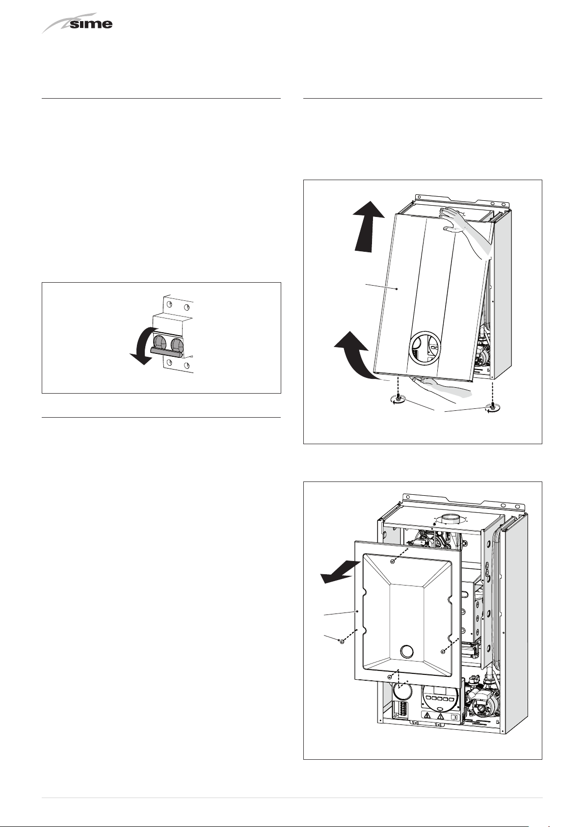
10 MAINTENANCE
OFF
1
3
4
10.1 Adjustments
For the appliance to operate correctly and efficiently it is
recommended that the User calls upon the services of a
Professionally Qualified Technician to carry out
maintenance.
m
a
CAUTION
The maintenance interventions described must ONLY
be carried out the professionally qualified personnel.
WARNING
Before carrying out any interventions described:
– set the main system switch to "OFF"
– close the gas valve
– make sure that no hot parts inside the appliance are
touched.
BI-ANNUAL
Fig. 56
10.3 Cleaning the inside of the appliance
10.3.1 Cleaning the heat exchanger
To clean the heat exchanger:
– disassemble the smoke outlet duct of the
– remove the screws (1), pull the front panel (2) forwards and
release it from the top by lifting it
2
Brava Slim 30 BFRe
10.2 External cleaning
10.2.1 Cleaning the cladding
When cleaning the cladding, use a cloth dampened with soap
and water or alcohol for stubborn marks.
d
IT IS FORBIDDEN
to use abrasive products.
– remove the four screws (3) and remove the front panel (4)
from the sealed chamber
Fig. 57
Fig. 58
42

– remove the four screws (3) and remove the front panel (4)
=
=
from the combustion chamber (6) working carefully so as not
to damage the gasket or the panel insulation
7
8
10.3.4 Final operations
After having cleaned the heat exchanger and the burner:
– remove any carbon residue using a vacuum cleaner
– check that the gasket and the insulation of the front panel (6)
of the combustion chamber and the gasket (13) of the front
panel (4) of the sealed chamber are all integral. If they are
not, replace them
– refit the panels (6) and (4) securing them with fastening
screws.
13
5 6
Fig. 59
– if there is any dirt on the heat exchanger (7) fins, protect the
burner elements (8) covering them with a sheet of newspaper
or a cloth and brush the heat exchanger (7) clean.
For more details refer to the drawings in the spare parts
catalogue.
10.3.2 Cleaning the burner
The burner does not require any particular maintenance simply
dust it with a soft brush
10.3.3 Checking the ignition/detection electrode
Check the state of the ignition/detection electrode and replace
if necessary. Check the measurements as per the drawing
whether the ignition/detection electrode is replaced or not.
+0.5
-0.5
3.5
Fig. 60
m
CAUTION
The position of the electrode is essential for the correct
detection of current ionization.
4
3
Fig. 61
10.4 Checks
10.4.1 Checking the smoke duct
It is recommended that the user checks that the combustion air
inlet duct and smoke outlet duct are integral and airtight.
10.4.2 Checking the expansion vessel pressure
It is recommended that the expansion vessel on the water side
is drained and that the prefilling pressure is not less than
(100 kPa)
. If this is not the case, pressurize it to the correct value
(see sectionExpansion vessel".
Once the checks described above have been completed:
– refill the boiler as described in section "REFILL operations"
– start the boiler up and carry out a smoke analysis and/or
measure the combustion efficiency.
– refit the front panel securing it with the two screws which
were removed previously
1 bar
10.5 Unscheduled maintenance
If replacing the
parameters as indicated in the table.
Type
No.
PAR 01
PAR 02
PAR 03
PAR 04
electronic board
Description
Index showing boiler power in kW
0 = 24; 1 = 30; 5 = AUS
Hydraulic configuration
0 = rapid
1 = storage tank with thermostat or
heating only
2 = hot water tank with sensor
3 = bithermic
4=instant with solar power input
Gas Type Configuration
0 = NATURAL GAS; 1 = UNIVERSAL LPG
Combustion configuration
0 = sealed chamber with combustion
control
1 = open chamber with smoke
thermostat
2 = Low NOx
, the user MUST set the
Setting for
Brava Slim 30
BFR
30
BFRi
30
BFRe
5
1
0 or 1
0
43

To enter "Parameter setting and display"refer to the indications
provided in the specific section.
Once the parameters in the table have been set, you must carry
out the "Automatic calibration procedure".
gas valve
If the
fan
are replaced, the user must still carry out the entire phase
and/or the
ignition/detection electrode
and/or the
of "Automatic calibration procedure" described in the specific
section.
10.6 Possible faults and solutions
LIST OF MALFUNCTION/FAULT ALARMS
Type No. Fault Solution
ALL 02
ALL 03
ALL 04 -
ALL 05 Delivery sensor fault
ALL 06 No flame detection
ALL 07
ALL 08
ALL 09
ALL 10 Auxiliary sensor fault
ALL 11
ALL 12
ALL 17
Low water pressure in
system
High water pressure in
system
Intervention of the
second element of the
delivery sensor
Fault in the flame
detection circuit
No water circulating in
the system
Gas valve modulator
disconnected
Incorrect configuration
of the open /sealed
chamber
Fault regarding
maximum deviation
between the 2 NTC
heating sensors
- Restore pressure
- Check for any leaks in
the system
- Empty the system via
the drain valve on the
hydraulic assembly and
bring the pressure to
approximately 1.2 bar
(120 kPa)
- Check connections
- Replace the sensor
- Check the integrity of
the electrode and check
that it is not grounded
- Check gas availability
and pressure
- Check the integrity of
the gas valve and the
card
- Check the delivery
sensor connections
- Deaerate the system
- Check the bleed valve
- Replace the delivery
sensor
- Check that the pump
impeller is not blocked
- Check the integrity of
the electrode and check
that it is not grounded
- Check gas availability
and pressure
- Check the integrity of
the gas valve and the
card
- Check the rotation of
the pump rotor
- Check the electrical
connections
- Replace the pump
- Check PAR
02 "hydraulic
configuration"
- Check the electrical
connection
- Check the electrical
connection
- Set the parameter
tS 0.4 (Combustion
configuration) to 0
- Replace the dual
sensor
ALL 28
ALL 37
ALL 40
ALL 41
ALL 42 Button fault
ALL 43
ALL 44
ALL 62
ALL 72
ALL 74
ALL 80
ALL 81
ALL 83
ALL 88
ALL 96
- -
- -
Maximum number of
consecutive resets
reached
Fault due to low network
voltage.
Incorrect network
frequency detected
Flame loss more than 6
consecutive times
Open Therm
communication fault
Anomaly inside electronic
board
The self-calibrating
procedure must be
carried out
Incorrect positioning of
the delivery sensor
Fault in the 2nd element
of the delivery sensor
Anomaly in gas valve
control line
Block due to combustion
during start-up
Irregular combustion
(temporary error)
Anomaly inside electronic
board
Block due to clogging in
smoke outlet
Frequent relief valve
intervention
Limited production of
domestic hot water
- Disconnect and
reconnect the power
- If the alarm persists,
contact the Technical
Assistance Centre
- Check with tester
- Contact network
provider (ENEL)
- Contact network
provider (ENEL)
- Check the detection
electrode
- Check the gas supply
(open valve)
- Check mains gas
pressure
- Check that buttons are
working
- Check the electrical
connection of the
remote control
- Replace the board
- Carry out the selfcalibrating procedure
(see the specific
section)
- Check that the delivery
sensor is attached to
the delivery pipe
- Replace the sensor
- Check/replace the
connection cable to the
gas valve
- Check for blockage in
chimney
- Bleed the air from the
gas circuit
- Check for blockage in
chimney
- Replace the board
- Check for blockage in
chimney
- Check circuit pressure
- Check expansion vessel
- Check the diverter valve
- Check that plate heat
exchanger is clean
- Check domestic hot
water circuit valve
44

11 COMMISSIONING BOILER CHECKLIST
ü
A suggested method of commissioning the boiler; the actual method can vary according to the boiler make, type and installation. The
boiler must always be installed and commissioned by an approved gas technician. The installer certifies that this Boiler has been
installed to the manufacturer's instructions, has been filled, commissioned and is ready for use.
N° Description
When done
1 Read carefully the instruction manuals supplied with this boiler.
2 BEFORE INSTALLING T HIS BOILER FLUSH OUT THE PIPES UNTIL CLEAN WATER IS ACHIEVED.
Turn off all services to–this boiler - water, gas and power.
3
Install the boiler as shown in the instructions following and connect all services.
Turn on water to fill system, check for leaks regularly and bleed air from all points.
4
Bleed the air from all the pumps in the system, and rotate the impeller shaft.
Check that all radiators valves are open, remove the thermostatic valve heads, fully open all
5
lockshield valves.
Turn ON gas, bleed air out at the isolation valve union. Reseal and check for gas leaks.
6
Turn gas OFF.
Turn electricity on at the power point. At the boiler front panel set the temperature setting to the
7
lowest setting, switch boiler to ON position.
The “Power on” Indicator should light. Turn the boiler off at the front panel.
Turn the room thermostat to the manual ON position set the temperature to a high level so that it
8
does not switch off during the commissioning phase. The thermostat will unusually click and show an
an indicator in the window.
9 Switch the boiler ON at the boiler front panel control.
Boiler should start fan, pump and ignite gas. If it fails first few times this may be just residual air in
10
the gas line. A noisy water pump indicates there is air in the water pipes.
Boiler lights and heats the water. Check gas flame is the correct colour and for gas and water leaks
11
as the system heats up.
Check that heat is going to all radiators through the manual or thermostatic first and return via the
12
lockshield valve. If not STOP fix NOW and any leaks.
Allow the boiler to heat up to the set temperature and switch off. Re-adjust the boiler temperature to
13
a mid temperature point. CAUTION, If this is connected to a floor heating system. The boiler should re
light and increase the water temperature to the new setting.
Check that all radiators are hot all the way up. If the radiator is cold at the top, then there is usually
14
air in the radiator Bleed the radiator. Balance the system so that all. radiators are hot as according to
the radiator installation manual. Adjust the boiler water temperature.
Set the room thermostat to the correct times and temperatures according to the manufacture's
15
instructions.
On completion of the commissioning phase, complete the information sheet at the front of this
manual. Hand over the installation to the owner and demonstrate how the system works plus basic
16
fault resolution and safety procedures. Make sure that this important document is kept in a safe
accessible place.
45
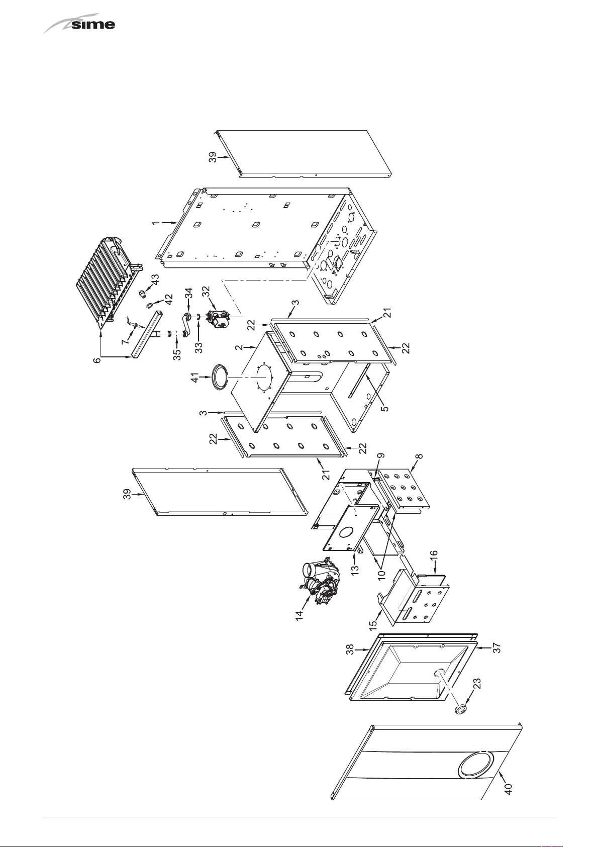
12 EXPLODED VIEWS
Brava Slim 30 BFRi
46
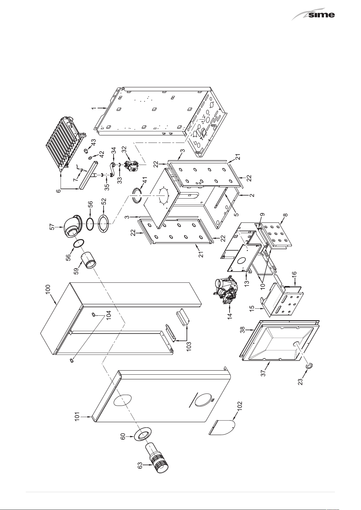
Brava Slim 30 BFRe
47

Brava Slim 30 BFRi
-
Brava Slim 30 BFRe
48

Brava Slim 30 BFRi
-
Brava Slim 30 BFRe
49
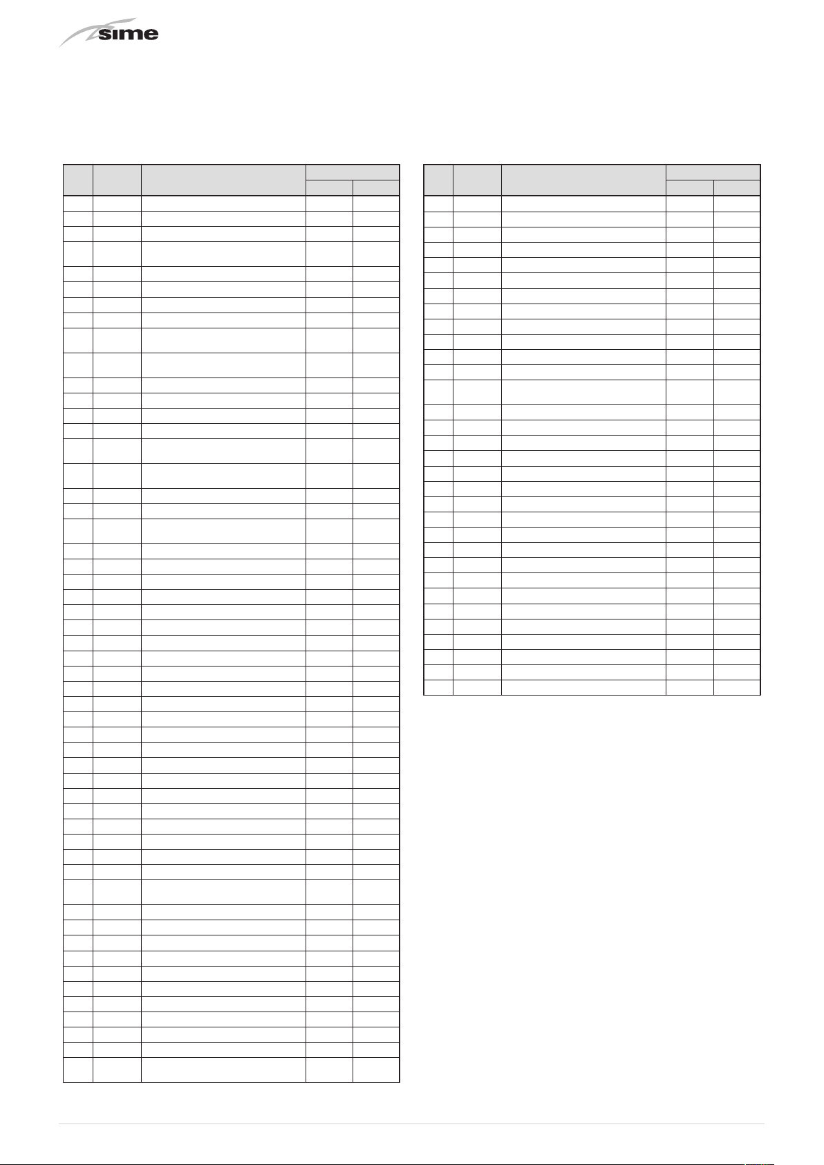
Pos. Code Description
BRAVA SLIM BFR
30 i 30 e
1 6264561 Boiler fixing bracket x x
2 6317611 Sealed chamber rear panel x x
3 6229838 Gasket for sealed chamber x x
4 5183729
Rectang. expans.vessel 9 l.
3/8" M
x x
5 6257532 Air deflector x x
6 5198265 Main burner assembly x x
7 6235935 Ignition-ionisation electrode x x
8 6318530 Smoke chamber assembly x x
9 6318741
10 6318710
Combustion chamber rear
insulation
Combustion chamber side
insulation
x x
x x
11 6174265 Gas/Water heat exchanger x x
12 6231362 NTC sensor x x
13 6318610 Smoke chamber front panel x x
14 6225643 Fan x x
15 6317910
16 6318731
Combustion chamber front
panel
Combustion chamber side
insulation
x x
x x
17 6264868 C.H. return pipe x x
18 6226412 O-ring 3068 x x
19 6226601
Spring for heat exchanger
connection
x x
20 6227465 Flowing pipe to C.H. system x x
21 6288210 Sealed chamber side panel x x
22 6229837 Gasket for sealed chamber x x
23 6001210 Peephole x x
26 2030267 Piracriten gasket Ø 30x17x2 x x
28 6017405 Flexible pipe M.F. 3/8" L=300 x x
29 6226476 ORing diam.15x2 x x
30 6226643 Pipe fixing spring x x
31 2030226 Gasket Ø 10.2x14.8x2 x x
32 6243838 Gas valve x x
33 2030249 Gasket Ø 24x17x3 x x
34 6195216 Gas inlet pipe x x
35 2030255 Gasket Ø 12.5x18.5x3 x x
37 6317711 Sealed chamber front panel x x
38 5192208 Gasket for sealed chamber x x
39 6304480 casing left/right side panel x
40 6325011 Casing front panel x
41 6028620 Air diaphragm Ø 81 x x
42 6022004 Copper washer Ø 6 x x
43 6154408 Main burner nozzle ø 1.50 x x
43 6154425 Nozzle M6X0.75-D.0.86 LPG x x
46 6120560 Pump nipple 3/4" x x
47 6226644
Spring clip for rotating connection
x x
48 6226475 ORing diam.18.64x3.53 x x
49 6272348 Modulating circulating pump x x
50 6013182 Automatic air vent x x
51 6147401 Plug 1/4" x x
52 6028702 Gasket Ø 95x125x2 x
53 6265835 C.H. return manifold x x
54 6040225 Pressure relief valve 1/2" 3 bar x x
55 6226645 Spring clip x x
56 6226404 Rubber gasket OR 308 Ø 60.3 x
57 6226251 Flanged elbow Ø 95 mm x
58 6265895
Flowing to C.H. system manifold
x x
Pos. Code Description
BRAVA SLIM BFR
30 i 30 e
59 6230710 Flue duct extension x
60 6230400 Rubber sealing ring Ø 100 mm x
61 2030225 Gasket Ø 5.5x11x2 x x
62 6229500 Plug 1/2" x x
63 6230302 Flue terminal x
68 6277798 Pipe connecting x x
70 6304720 Control panel x x
75 6305140 Rubber cap x x
76 6245380 Pump connector x x
78 6304831 Interface panel x x
79 6305131 Rubber button x x
81 6324900 Main P.C.B. x x
84 6275911
Pressure relief valve operation
lever
x x
86 2030227 Gasket Ø 12x18x2 x x
87 2030228 Gasket Ø 17x24x2 x x
88 6157653 Pressure relief valve drain pipe x x
100 6255818 Boiler casing x
101 6255885 Casing door x
102 6255913 Flap door x
103 6262910 Boiler casing support x
104 6133100 Pin M5 ZnCr x
700 6281534 Gaskets kit x x
701 6319695 Murelle-Format-.....o-ring kit x x
702 6319700 Springs / clamps kit DIN x x
703 5202340 Complete control panel x x
704 6323876 4 pole cable connector CN14 x x
705 6323878 9 pole cable connector CN1 x x
706 6323883 4 pole cable connector CN13 x x
707 6325602 6 pole cable connector CN12 x x
708 6325641 14 pole cable connector x x
709 5144726 Conversion kit to LPG x
710 5144726 Conversion kit to LPG x
50

13 REMOVING COMPONENTS
1
3
3
4
m
a
CAUTION
The maintenance interventions described must ONLY
be carried out the professionally qualified personnel.
WARNING
Before carrying out any interventions described:
– set the main system switch to "OFF"
– close the gas valve
– make sure that no hot parts inside the appliance are
touched.
13.1 Remove panels
13.1.1 Front panel
To access the internal parts of the boiler:
– disassemble the smoke outlet duct of the
– remove the screws (1), pull the front panel (2) forwards and
release it from the top by lifting it
Brava Slim 30 BFRe
13.1.2 Side panels
– Unscrew the screws (3)
– pull the side panel (4) outwards to release it from the top
4
2
– proceed in the same way for the other panel.
13.1.3 Sealed chamber panel
– remove the four screws (3) and remove the front panel (4)
from the sealed chamber
Fig. 62
Fig. 63
Fig. 64
51

13.1.4 Combustion chamber panel
3
5
– remove the four screws (3) and remove the front panel (4)
from the combustion chamber (6) working carefully so as not
to damage the gasket or the panel insulation
5 6
Fig. 65
13.3 Dual sensor (thermal safety/discharge)
– Remove front panel (see "Remove panels" on page 51)
– disconnect the connector (1)
1
13.2 Rotate control panel
– Remove front panel (see "Remove panels" on page 51)
– remove the screws (3) securing the control panel (4)
– move the panel (4) upwards (a) but keeping it in the side
guides (5) to the end of travel
– bring it forwards and down (b) until it is horizontal
4
b
a
Fig. 66
Fig. 67
– remove the rear locking clip (2)
– disconnect the sensor (3) from the pipe
3
2
Fig. 68
52

13.4 Remove electronic board
A
1
7
– Remove front panel (see "Remove panels" on page 51)
– move the control panel (A) into a horizontal position (see "
Rotate control panel" on page 52)
– unscrew the screw (1)
– press the catches (2) to remove the cover
13.5 Remove/replace fan
– Remove front panel (see "Remove panels" on page 51)
– Remove the front panel of the sealed chamber (see "Sealed
chamber panel" on page 51)
– Remove the front panel of the combustion chamber (see "
Combustion chamber panel" on page 52)
– disconnect the fan connectors (7)
– unscrew the three screws (8)
2
– open the cover (3)
3
– unscrew the fixing screw (4) on the electronic board
– remove the electronic board (5) by sliding upwards
– disconnect all the connectors (6)
2
Fig. 69
8
Fig. 72
– extract the fan from underneath
Fig. 70
4
6
5
Fig. 73
Fig. 71
53
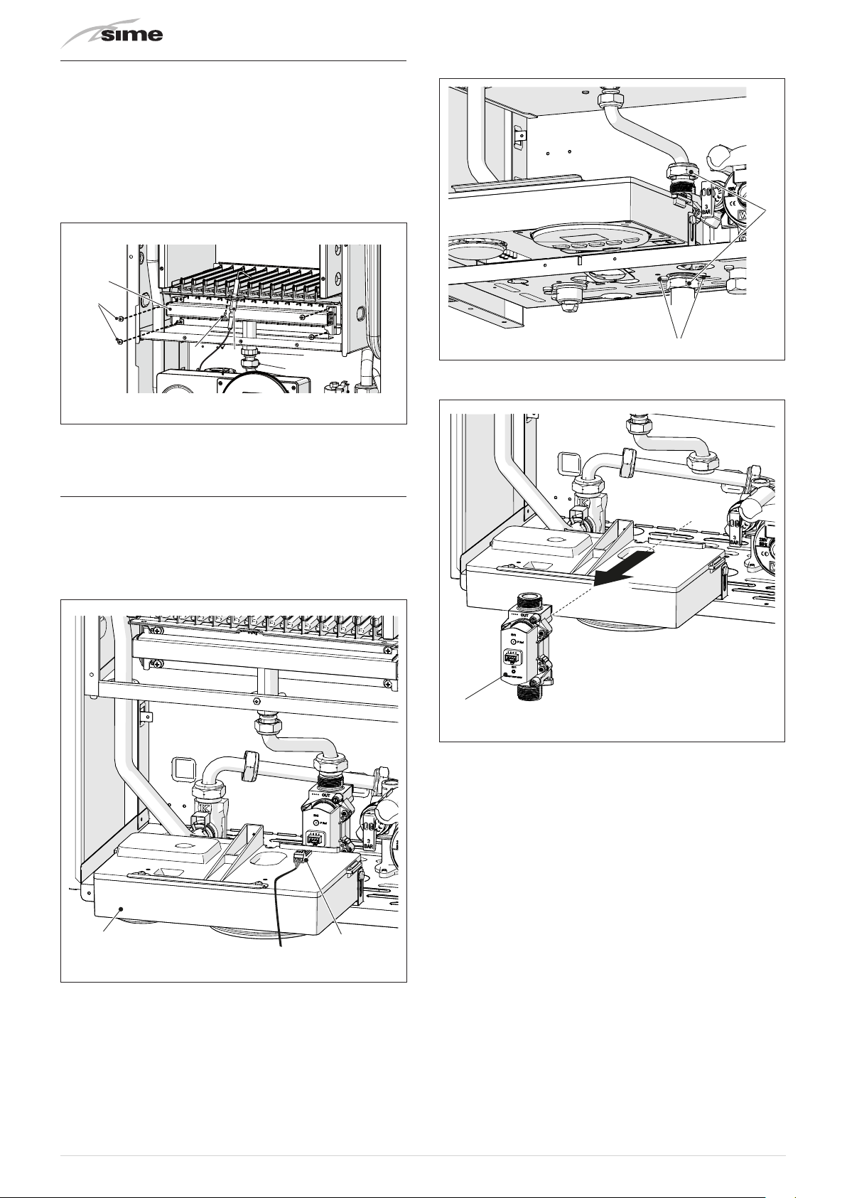
13.6 Remove/replace ignition electrode and
3
nozzles
– Remove front panel (see "Remove panels" on page 51)
– Remove the front panel of the sealed chamber (see "Sealed
chamber panel" on page 51)
– Remove the front panel of the combustion chamber (see "
Combustion chamber panel" on page 52)
– remove the swivel joint (9) and the counter-nut (10)
– remove the screws (11)
– remove the gas collector (12) and replace the factory nozzles
12
11
– unscrew the swivel joints (3) and the screws (4)
7
8
– unscrew the screw (7)
– remove the ignition electrode (8)
10
9
Fig. 74
13.7 Remove/replace gas valve
– Close the gas valve
– remove the front panel (see "Remove panels" on page 51)
– move the control panel (A) into a horizontal position (see "
Rotate control panel" on page 52)
– disconnect the electrical connector (2)
Fig. 76
– extract the gas valve (5)
5
Fig. 77
A
54
2
Fig. 75

13.8 Remove/replace the expansion vessel
1
4
3
5
3
m
– Shut-off the valves to the system and empty the boiler
– remove the front panel (see "Remove panels" on page 51)
– disconnect the pipe (1)
– unscrew the fixing screw (2) on the rear panel
CAUTION
When disassembling, some residual water may leak.
2
13.9 Remove/replace system pump
– Shut-off the valves to the system and empty the boiler
– remove the front panel (see "Remove panels" on page 51)
– lift the connector (1) using a screwdriver (2)
1
2
Fig. 78
– release the top section (4)
– pivoting around the hook (5), turn and extract the expansion
vessel (3)
5
Fig. 80
– unscrew the swivel joints (3) and (4)
– disconnect the pipes (5) and (6)
– unscrew the screw (7)
– unscrew the nut (8) that secures the pump
7
8
4
Fig. 79
6
Fig. 81
55

565758


59

Fonderie Sime S.p.A - Via Garbo, 27 - 37045 Legnago (Vr)
Tel. +39 0442 631111 - Fax +39 0442 631292 - www.sime.it
Fonderie SIME S.p.A.reserves the right to make changes at any time without prior notice in order to improve its products
without compromising the essential characteristics.
 Loading...