


Remove the “Testing Certificate” from inside the combustion chamber and
keep together with the instructions manual.
The package of the “2R GT” boiler contains instructions for installation, operation and maintenance of the diesel burner.
CONTENTS
1 BOILER DESCRIPTION
1.1 INTRODUCTION . . . . . . . . . . . . . . . . . . . . . . . . . . . . . . . . . . . . . . . . . . . . . . . . . . . . . . . . . . . . . . . . . . . . . . . . . . . . . . . . . . . . . . . . . . . 24
1.2 DIMENSIONAL DETAILS
1.3 TECHNICAL FEATURES
1.4 LOSS OF HEAD . . . . . . . . . . . . . . . . . . . . . . . . . . . . . . . . . . . . . . . . . . . . . . . . . . . . . . . . . . . . . . . . . . . . . . . . . . . . . . . . . . . . . . . . . . . . 25
1.5 COMBUSTION CHAMBER DIMENSIONS . . . . . . . . . . . . . . . . . . . . . . . . . . . . . . . . . . . . . . . . . . . . . . . . . . . . . . . . . . . . . . . . . . . . . 26
1.6 SOME BURNER BRANDS COMPATIBLE WITH “1R/2R” BOILERS
2INSTALLATION
2.1 BOILER ROOM . . . . . . . . . . . . . . . . . . . . . . . . . . . . . . . . . . . . . . . . . . . . . . . . . . . . . . . . . . . . . . . . . . . . . . . . . . . . . . . . . . . . . . . . . . . . . 27
2.2 BOILER ROOM DIMENSIONS
2.3 CONNECTING UP SYSTEM
2.4 CONNECTING UP FLUE
2.5 BOILER BODY ASSEMBLY . . . . . . . . . . . . . . . . . . . . . . . . . . . . . . . . . . . . . . . . . . . . . . . . . . . . . . . . . . . . . . . . . . . . . . . . . . . . . . . . . . 28
2.6 FITTING THE CASING
2.7 ELECTRICAL CONNECTION . . . . . . . . . . . . . . . . . . . . . . . . . . . . . . . . . . . . . . . . . . . . . . . . . . . . . . . . . . . . . . . . . . . . . . . . . . . . . . . . . 29
2.8 ASSEMBLY OF “RVA 43.222” CLIMATE CONTROLLER . . . . . . . . . . . . . . . . . . . . . . . . . . . . . . . . . . . . . . . . . . . . . . . . . . . . . . . . . 30
3 USE AND MAINTENANCE
3.1 COMMISSIONING THE BOILER . . . . . . . . . . . . . . . . . . . . . . . . . . . . . . . . . . . . . . . . . . . . . . . . . . . . . . . . . . . . . . . . . . . . . . . . . . . . . . 31
3.2 LIGHTING AND OPERATION
3.3 CLEANING THE BOILER
3.4 USER WARNINGS
3.5 HOW TO USE THE “RVA 43.222” . . . . . . . . . . . . . . . . . . . . . . . . . . . . . . . . . . . . . . . . . . . . . . . . . . . . . . . . . . . . . . . . . . . . . . . . . . . . 32
1R - 2R - 2R GT
ENGLISH

24
1.1 INTRODUCTION
The cast iron boilers “1R/2R freestanding” for gas-oil or gas has been desi-
gned in compliance with the European
Directives 90/396/CEE, 89/336/CEE,
73/23/CEE, 92/42/CEE.
The cast iron boilers “2R GT” for gas-oil
has been designed in compliance with
the European Directive 92/42/CEE.
The components for “1R/2R free-
standing” installation are supplied in
three separate packages: boiler body,
casing with enclosed documents and
control panel.
“2R GT” boilers are supplied in four
separate packages: boiler body, casing
with enclosed documents, control
panel and burner with instructions.
1BOILERDESCRIPTION
1R6 1R7 1R8 1R9
Output kW 64.8 74.0 84.0 93.3
kcal/h 55,700 63,600 72,200 80,200
Input kW 73.4 83.1 93.8 103.4
kcal/h 63,100 71,500 80,700 88,900
P (depth) mm 595 670 750 825
Sections n° 6 7 8 9
Maximum water head bar 4 4 4 4
Water content l37.542.046.551.0
Loss of head
Smoke mbar 0.20 0.16* 0.22* 0.30*
Water (Δt 10°C) mbar 30.0 34.0 40.0 45.5
Comb. chamber pressure mbar – 0.01 0.06 0.08 0.08
Suggested chimney depression
mbar 0.21 0.22 0.30 0.38
Smokes temperature °C 225 217 209 201
Smokes flow m
3
n/h 68.0 77.7 88.0 97.6
Adjustment range
Heating °C 30÷85 30÷85 30÷85 30÷85
Smokes volume dm
3
42 46 50 55
Weight kg 261 293 325 357
1.3 T EC HN IC AL F EAT UR ES
1.3.1 “1R” boiler
560 (1R) - 700 (2R)
P
125 (1R)
135 (2R)
ø 150 (1R)
ø 200 (2R)
270 (1R)
330 (2R)
925 (1R) - 1130 (2R)
70 (1R)
85 (2R)
695 (1R) - 875 (2R)
865 (1R) - 1075 (2R)
R
S
M
1.2 D IM EN SI ON AL DE TAI LS
Fig. 1
1R 2R/2R GT
MC.H. flow 1
1
/
2
”2”
R C.H. return 1
1
/
2
”2”
S Boiler/filling drain 3/4” 3/4”
* Without baf fles
25
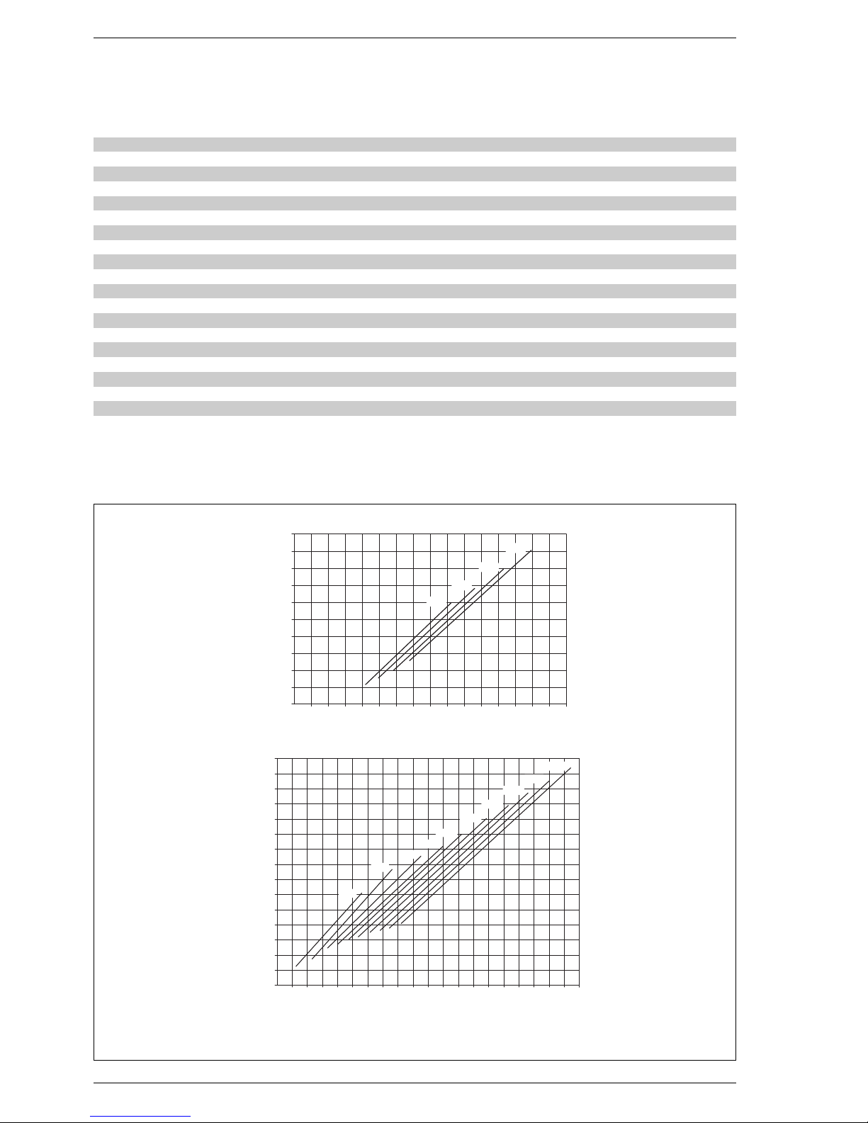
1.4 LOS S OF H EA D
1.3. 2 “2 R/ 2R G T” b oi le r
Fig. 2
NOTE: The losses of head shown in the diagram were obtained with a Δt of 10°C
“1R” boiler
“2R/2R GT” boilers
6789101112131415
Output kW 100.6 123.8 147.1 165.1 179.7 197.7 213.4 230.2 248.8 266.9
kcal/h 86,500 106,500 126,500 142,000 154,500 170,000 183,500 198,000 214,000 229,500
Input kW 113.5 139.1 164.7 184.1 199.7 219.7 237.1 255.8 276.4 296.7
kcal/h 97,600 119,700 141,600 158,300 171,700 188,900 203,900 220,000 237,700 255,200
P (depth) mm 735 835 935 1,035 1,135 1,235 1,335 1,435 1,535 1,635
Sections n° 6 7 8 9 10 11 12 13 14 15
Max. water head bar 5 5 5 5 5 5 5 5 5 5
Wate r content l92107122136151165180194209223
Loss of head
Smoke mbar 0.10 0.15 0.22 0.29 0.24* 0.37* 0.39* 0.42* 0.49* 0.50*
Water (Δt 10°C) mbar 61.0 76.0 85.0 92.0 100.0 1,120 118.0 121.0 125.0 130.0
Comb. chamb. press. mbar – 0.02 – 0.02 – 0.01 – 0.02 – 0.02 – 0.01 – 0.02 0.31 0.35 0.50
Suggested chimney depress.
mbar 0,12 0,17 0,23 0,31 0,26 0,38 0,41 0,73 0,84 1,00
Smokes temperature °C 238 236 234 232 229 224 219 215 211 207
Smokes flow m
3
n/h 105.2 129.2 153.3 171.9 186.9 205.4 221.6 238.9 257.9 276.6
Adjustment range
Heating °C 30÷85 30÷85 30÷85 30÷85 30÷85 30÷85 30÷85 30÷85 30÷85 30÷85
Smoke volume dm
3
83 92 101 110 119 128 138 147 157 167
Weight kg 462 520 578 636 676 734 792 850 908 966
12345678
0
10
20
30
40
50
Portata m3/h
Δp mbar
1R 8
1R 7
1R 6
1R 9
4 5 6 7 8 9 10 11 121314 15 16 17 18 19
0
20
40
60
80
100
Portata m3/h
Δp mbar
2R 6
2R 7
2R 9
2R 8
120
20 21 22 23
140
2R 10
2R 11
2R 12
2R 13
2R 14
2R 15
* Without baf fles
Flow m3/h
Flow m3/h

26
1.5 COMBUSTION CHAMBER
DIMENSIONS
The dimensions of this direct passage
combustion chamber are reported in
fig. 3.
Fig. 3
“1R” 6789
A mm 310 310 310 310
B mm 310 310 310 310
L mm 448 524 600 676
Volume m
3
0,038510 0,045129 0,051748 0,058367
“2R - 2R GT” 6789101112131415
A mm 390 390 390 390 390 390 390 390 390 390
B mm 430 430 430 430 430 430 430 430 430 430
L mm 570 670 770 870 97 0 1.070 1.170 1.27 0 1.370 1.470
Volume m
3
0,081690 0,096314 0,110938 0,125562 0,140186 0,154810 0,169434 0,184058 0,198682 0,213306
1.6 SOME BURNER BRANDS COMPATIBLE WITH “1R/2R” BOILERS
In general, the oil burner that is compatible with the boiler should use full spray nozzles.
1.6.1 ECOFLAM gas-oil burners
1.6.2 RIELLO gas-oil burners
Boiler Model Atomising
Gulliver R. 40 REG R2000 angle
1R6 RG2 - RG2D G10 – G120 60°
1R7 RG2 - RG2D G10 – G120 60°
1R8 RG2 - RG2D G10 – G120 60°
1R9 RG2 - RG2D - RG3 - RG3D G10 - G20 – G214 - G230D 60°
2R6 RG3 - RG3D G20 – G214 - G230D 60°
2R7 RG3 - RG3D G20 – G214 - G230D 60°
2R8 RG3 - RG3D G20 – G214 - G230D 60°
2R9 RG3 - RG3D G20 - G20D – G214 - G230D 60°
2R10 RG4S - RG4D - RG5D G20 - G20D – – 60°
2R11 RG4S - RG4D - RG5D G20 - G20D – – 60°
2R12 RL28/1 - RL28/2 - RG5D – – – 60°
2R13 RL28/1 - RL28/2 - RG5D – – – 60°
2R14 RL28/1 - RL28/2 - RG5D – – – 60°
2R15 RL28/1 - RL28/2 - RG5D – – – 60°
Boiler Model Atomising
1 flame 2 flames angle
1R6 MINOR 8 – 60°
1R7 MINOR 8 – 60°
1R8 MINOR 12 – 60°
1R9 MINOR 12 – 60°
Boiler Model Atomising
1 flame 2 flames angle
2R6÷8 MAIOR P 15 MAIOR P 15 AB 60°
2R9÷12 MAIOR P 25 MAIOR P 25 AB 60°
2R13-14 MAIOR P 35 MAIOR P 35 AB 60°
2R15 –MAIOR P 45 AB60°
1.6.3 F.B.R. gas-oil burners
Boiler Model Atomising
angle
1R6÷8 G2 2001 60°
1R9 - 2R6 G2 MAXI 60°
2R7 FG 14 TC 60°
Boiler Model Atomising
angle
2R8 FG 14 TC 60°
2R9÷13 G 20 TC 60°
2R14-15 G 30/2 TC 60° - 45°

27
2.1 BOILER ROOM
The boiler room should feature all the
characteristics required by standards
governing liquid fuel heating systems.
2.2
BOILER ROOM DIMENSIONS
Position the boiler body on the foundation bed, which should be at least 10
cm high. The body should rest on a
surface allowing shifting, possibly by
means of sheet metal.
Leave a clearance between the boiler
and the wall of at least 0.60 m, and
between the top of the casing and the
ceiling of 1 m (0.50 m in the case of
boilers with incorporated D.H.W. tank).
The ceiling height of the boiler room
should be less than 2.5 m.
2.3 CONNECTING UP SYSTEM
When connecting up the water supply
to the boiler, make sure that the specifications given in fig. 1 are observed.
All connecting unions should be easy
to disconnect by means of tightening
rings.
A closed expansion tank system
must be used.
2.3.1 Filling the water system
Before connecting the boiler, thoroughly flush the system to eliminate
scale which could damage the
appliance.
Filling must be done slowly so as to allow
any air bubbles to be bled off through the
air valves. In closed-circuit heating
systems, the cold water filling pressure
and the pre-charging pressure of the
expansion vessel should be no less than
or equal to the height of the water head
of the installation (e.g. for water head of
5 metres, the vessel pre-charging pressure and installation filling pressure
should be at least 0.5 bar).
2.3.2
Water system
characteristics
Water supplying the heating circuit
must be treated in accordance with
UNI-CTI 8065 standards.
It is absolutely essential to treat water
in the heating system in the following
cases:
–for extensive systems (with high
contents of water);
–frequent addition of water into the
system;
– should it be necessary to empty the
system either partially or totally.
2.4 CONNECTING UP FLUE
The flue is of fundamental importance
for the proper operation of the boiler;
if not installed in compliance with the
standards, starting the boiler will be
difficult and there will be a consequent
formation of soot, condensate and
encrustation.
The flue used to expel combustion products into the atmosphere must meet
the following requirements:
–
be constructed with waterproof
materials, and resistant to smoke
temperature and condensate;
–be of adequate mechanical resilien-
ce and of low heat conductivity;
–be perfectly sealed to prevent coo-
ling of the flue itself;
–be as vertical as possible; the termi-
1.6. 5 Bu rn er f la nge
The dimensions of the diesel burner
anchorage flange are given in fig. 4.
2INSTALLATION
A
B
C
Fig. 4
ABC
mm mm ø
1R 6 110 15 0 M 8
1R 7÷9 13 0 17 0 M 8
2R 6-7 13 0 17 0 M 8
2R 8÷15 16 0 19 0 M 10
2R GT 6-7 13 0 17 0 M 8
2R GT 8÷15 16 0 19 0 M 10
1.6. 4 RI EL LO gas b ur ne rs
Boiler Model Output (kW) Electrical Gas
1°stage 2°stage data type
1R 6÷9 GS10 42÷116 – 230V
±
10% ~50Hz G20/25 - G30/31
2R 6 GS10 42÷116 – 230V
±
10% ~50Hz G20/25 - G30/31
2R 7÷8 BS 3 65÷189 – 230V
±
10% ~50Hz G20/25 - G30/31
2R 9÷11 BS 4 110÷246 – 230V
±
10% ~50Hz G20/25 - G30/31
2R 8÷15 RS 28 81 163-325 230V
±
10% ~50Hz G20/25 - G30/31
2R 8÷15 RS 28/1 163÷349 – 230V
±
10% ~50Hz G20/25 - G30/31
nal section of the flue must be fitted
with a static exhaust device that
ensures constant and efficient
extraction of products generated by
combustion;
–to prevent the wind from creating
pressure zones around the chimney
top greater than the uplift force of
combustion gases, the exhaust
outlet should be at least 0.4 m
higher than structures adjacent to
the stack (including the roof top)
within 8 m;
–have a diameter that is not inferior
to that of the boiler union: square or
rectangular-section flues should
have an internal section 10% greater than that of the boiler union;
–the useful section of the flue must
conform to the following formula:
S resulting section in cm
2
Kreduction coefficient for liquid
fuels:
–0.045 for firewood
– 0.030 for coal
– 0.024 for light oil
– 0.016 for gas
Pboiler input in kcal/h
H height of flue in metres, measu-
red from the flame axis to the
top of the flue reduced by:
–0.50 m for each change of
direction of the connection
union between boiler and flue;
–1.00 m for each metre of
union itself.
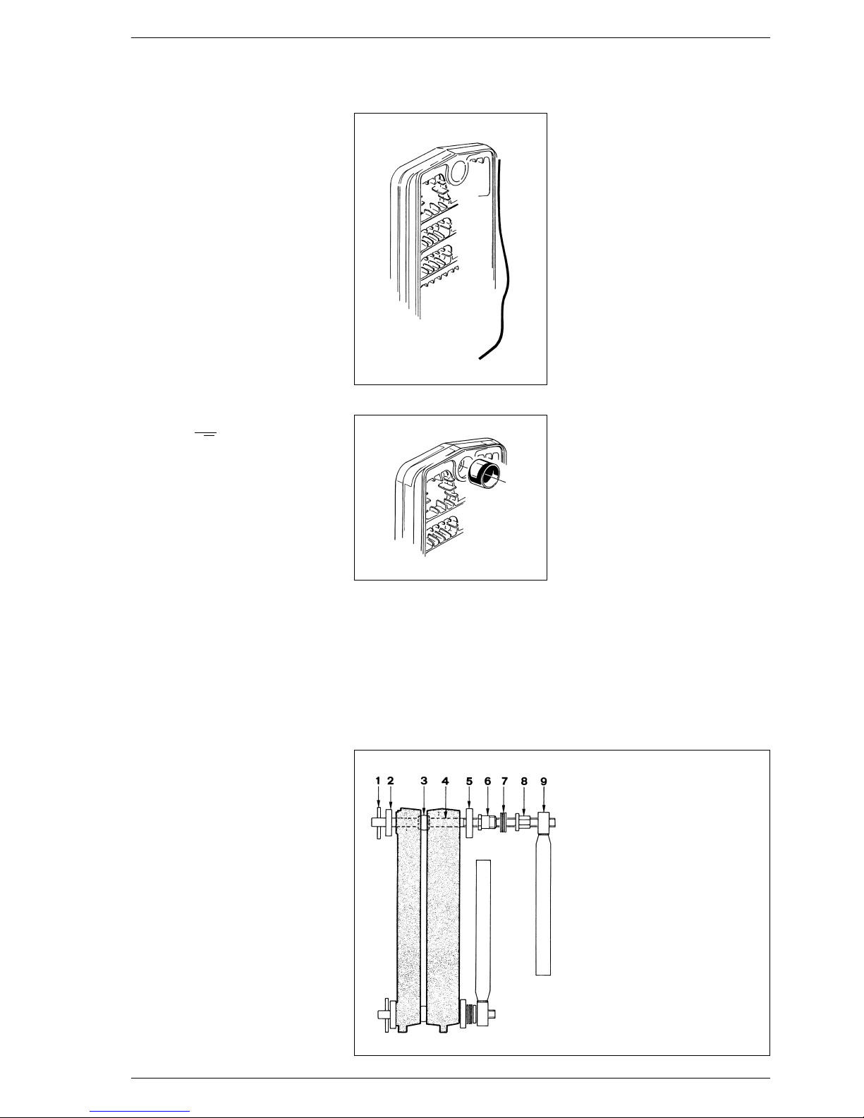
2.5 BOILER BODY ASSEMBLY
The boiler body comes supplied assembled. Where there is difficulty in gaining
access to the boiler room, the body can
be supplied in separate sections. For
assembly, proceed as follows:
–prepare the sections, cleaning the
seats of the tapered nipples with
solvent;
– insert the bead of putty (fig. 5) in the
groove provided for fume tightness,
pressing lightly;
– prepare one of the two intermediate
sections. After lubricating them with
boiled linseed oil, insert the tapered
nipples (fig. 6);
–prepare the head, proceeding as
above, and bring it up to the intermediate section. Add only one section at a time;
–
assemble the sections, using the
tools provided consisting of a pair of
staybolts for assembly with the corresponding accessories (code
6050900 - fig. 7), exerting pressure
simultaneously on the top hub and
on the bottom hub. If, during this operation, the sections were to slot
together in such a way as not to be
even and parallel, slide a chisel in the
tighter side and, by applying a little
force, bring the two pieces together
so that they are parallel.
The sections can be considered properly joined together when their
outer edges come into contact;
– insert the bead of putty in the groo-
ve of the section that has just been
assembled, and then proceed to joining up the other sections until the
body is completed.
NOTE: befo re proceeding to connect the system, test the boiler
block with a water pressure of 7.5
bar.
2.6 FITTING THE CASING
The casing and the control panel are
supplied in separate cardboard packages. The housing package also contains the boiler documents and the
glass wool for insulating the cast iron
body. To fit the casing, proceed as follows (fig. 8):
– fix the left front side angle bar (2)
and the right front side angle bar (3)
to the upper tie rods using the two
galvanized nuts provided;
– place the front cross bar (4) on the
lower tie rods before securing the
angle bars with the two cap nuts
provided;
– insulate the cast iron body with the
glass wool (1);
– fix the side parts (5) and (6) to the
angle bars using the ten self-tapping
screws provided, and secure them
at the back with the nuts placed on
the tie rods;
28
Fig. 5
Fig. 6
KEY
1 Pin
2Flange ø 35/87
3 Biconical nipples
4Staybolt L. 900 + staybolt L. 980
5Flange ø 50/87
6 Stub
7 Thrust bearing
8 Nut
9Tightening wrench
Fig. 7
P
S=K
√H
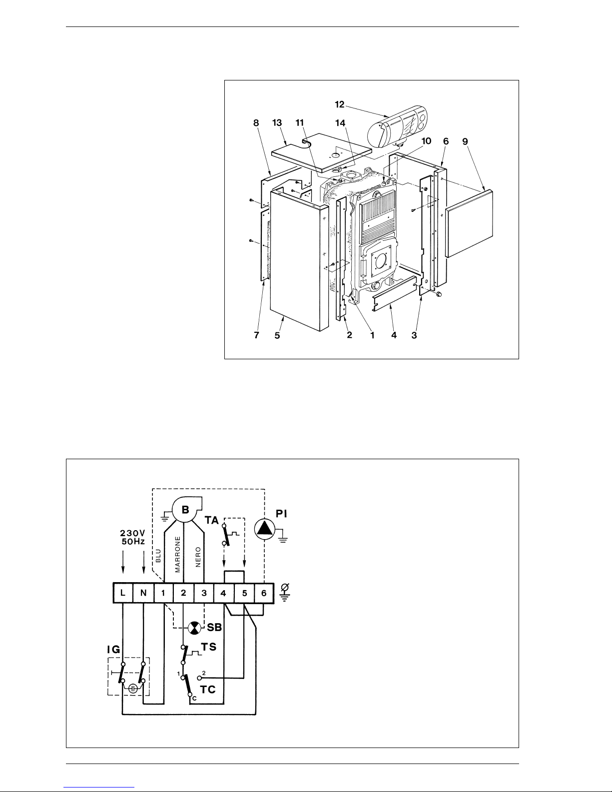
– assemble the lower rear panel (7)
with the eight self-tapping screws
provided;
–
assemble the upper rear panel (8)
with the six self-tapping screws provided;
– fix the control panel (12) to the cover
(13) using the check nut (14);
– unwind the capillary tubes of the two
thermostats and thermometer by
inserting their sensors inside the
sheath (11), securing the assembly
in position using the capillary tube
retaining spring provided;
– screw the water gauge to the check
valve (10);
– complete assembly by fixing the
cover (13) and the front panel (9) to
the side parts.
NOTE: Remove the “Testing Certificate” from inside the combustion
chamber and keep together with
the instructions manual.
2.7 ELECTRICAL CONNECTION
(figg. 9 - 9/a)
The boiler is fitted with an electricity
cable, and requires a a single-phase
power supply of 230V - 50Hz through the main switch protected by
fuses. The room thermostat (required for enhanced room temperatu-
re control) must be connected to
the terminals 4-5 after removing
the link. Connect the burner cable
supplied.
NOTE: Device must be connected to
an efficient earthing system. SIME
declines all responsibility for injury
caused to persons due to failure to
earth the boiler.
Always turn off the power supply
before doing any work on the electrical panel.
29
Fig. 8
KEY
IG Main switch
TA Room stat (not supplied)
PI C.H. pump (not supplied)
TC Boiler stat
TS Safety stat
B Burner (not supplied)
SB Burner lock-out lamp
NOTA: The room stat must be connected to the terminals 4-5 after
removing the link.
Fig. 9
“1R/2R” boilers
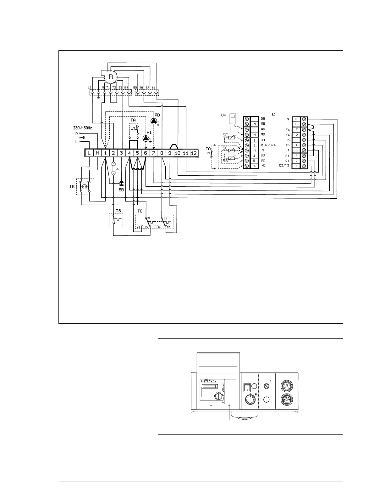
2.8 ASSEMBLING
THE RVA 43.222 CLIMAT
CONTROLLER (fig. 10)
All functions of the “2R GT” boiler may
be controlled using the controller, code
8096303, which is supplied with an
outdoor temperature probe (SE) and a
boiler immersion probe (SC).
The controller is to be connected to an
additional series of low voltage connectors for connection of the room temperature control unit (the connectors are
supplied in a bag inside the control
panel).
The probe bulb of the external hot
water tank, if any, (SS) code 6277110,
must be inserted in the hot water tank
sheath, while the bulb of the boiler
probe (SC) must be inserted in the boiler sheath.
When assembling the outdoor temperature probe, follow the instructions
provided in the probe package. Refer to
fig. 9/a for wiring instructions.
IMPORTANT:
To make sure that the unit works properly, set the boiler control thermostat as high as it will go.
30
Fig. 9/a
“2R GT” boiler
KEY
F Fuse (T 6A)
IG Main switch
SB Burner shutdown emergency light
TC Two-stage control thermostat
TS Safety thermostat
BBurner
PI System pump
PB Boiler pump
C Connectors for RVA 43.222 controller
(black - red - brown)
TA Environment thermostat
UA Type QAA70 room temperature control unit
(optional)
SE Outdoor temperature probe (optional)
SC Type QAZ21 boiler probe (optional)
SS Type QAZ21 hot water probe (optional)
NOTE: Connect the TA by removing the jumper
from terminals 4-5. Connect up the RVA43.222
control device and remove the jumpers from terminal boards 4-5, 4-6, 9-10
12
Fig. 10
KEY
1 Cover
2 RVA 43.222 controller
3.1 COMMISSIONING
THE BOILER
When commissioning the boiler it is
recommended:
–to make sure that the system has
been filled with water and adequately vented;
–to make sure that the flow and
return valves are fully open;
–to make sure that flue and chimney
are free from obstructions;
– to make sure that the electrical con-
nections to the mains and the
earthing are correct;
–
to make sure that no flammable
liquids or materials are near the
boiler.
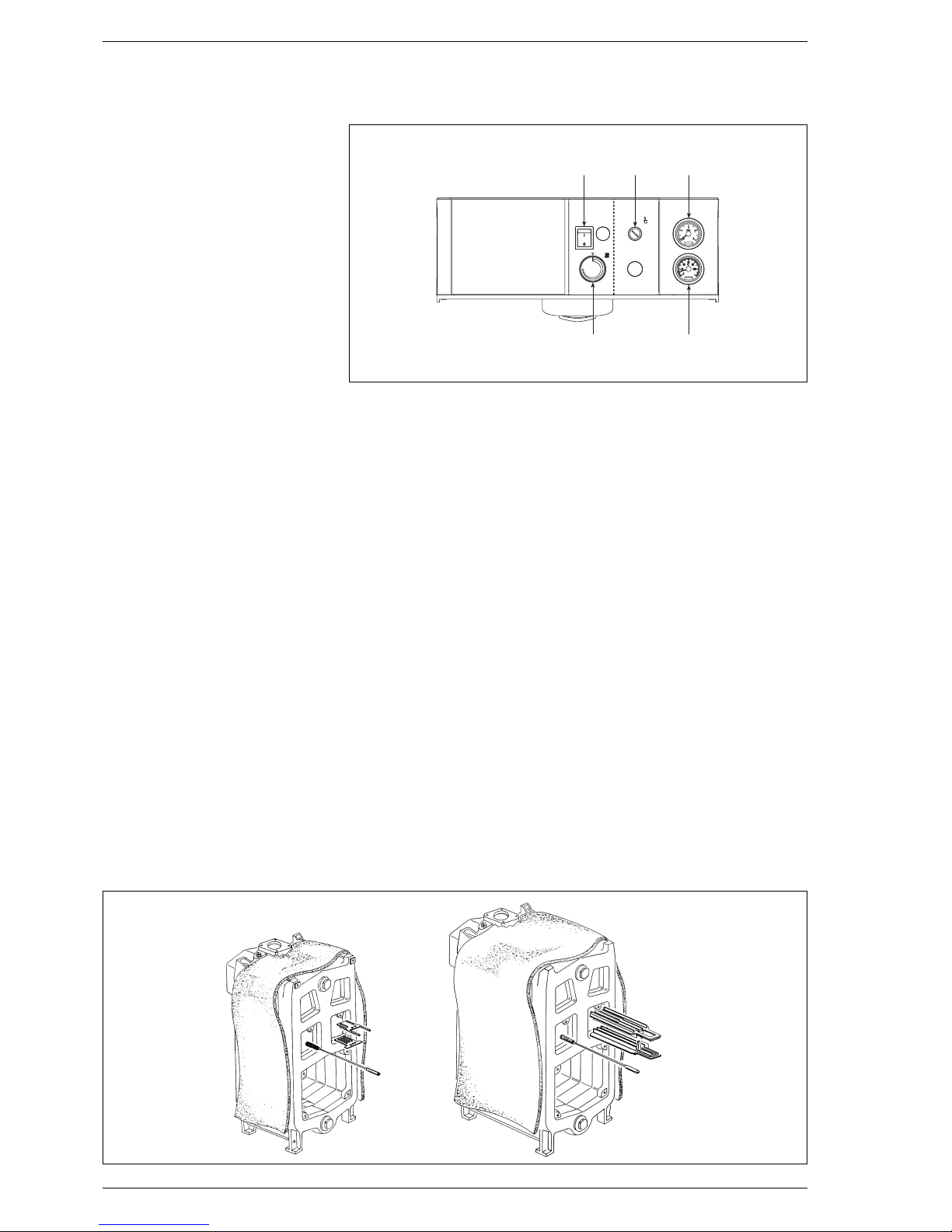
3.2 LIGHTING AND
OPERATION
3.2.1 Lighting the boiler
To lig h t t h e b oil e r p r oc e ed a s f ol l ow s
(fig. 11):
–check that the “Testing Certificate”
has been removed from inside the
combustion chamber;
–switch on the main switch (1); the
burner will start ;
–turn the boiler stat knob (5) to the
desidered setting.
For best results, set the boiler stat
knob to a temperature no lower
than 60°C to prevent the formation
of condensate.
The set temperature value can be
checked on the thermometer (4).
3.2.2 Safety stat
The safety stat with automatic reset
calibration set at 100°C (2 fig. 11)
trips, immediately turning off the burner when the boiler accidentally
overheats. To restore normal operations, wait until the temperature
drops below the thermostat calibration setting.
3.2.3 System filling
Periodically check the pressure values
of the hydrometer (3 fig. 11) which,
when the system is cold, should range
between 1 and 1.2 bar. If the pressure
is less than 1 bar, reset the system.
3.2.4 Turning OFF boiler
To turn off the boiler, cut off the voltage by pressing the mains switch (1
fig. 11).
3.3 CLEANING THE BOILER
(fig. 12)
The boiler body and flue should be
cleaned at the end of each season.
To clean the boiler, simply remove the
burner-holding plate and the cleaning
plate with their insulation and protection panels; this operation gives easy
access to the three front pockets and
the combustion chamber.
Before proceeding to clean the and
“1R 6 - 2R/2R GT 6 ÷ 9” models, the
baffles must be removed.
Once maintenance has been completed, reposition the baffles.
Use the pig to clean the smoke pipes.
NOTE: Preventive maintenance must
be carried out by authorized technical staff.
3.4 USER WARNINGS
When faults occur and/or the equipment does not operate correctly, turn
it off, without attempting to make any
repairs or take direct action.
For any operation only contact the
authorised technical personnel in your
area.
31
3 USE AND MAINTENANCE
Fig. 12
1 23
45
Fig. 11
“1R” boiler “2R/2R GT” boilers
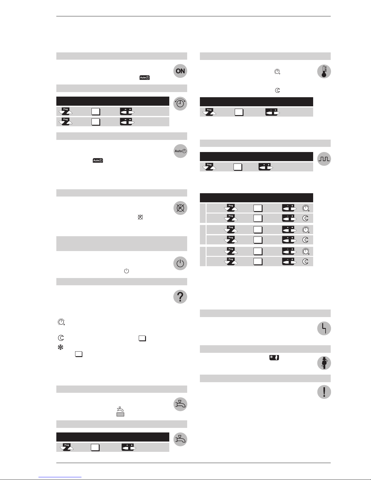
TO TURN ON THE HEATING
–Turn on the main switch.
– Set the correct hour of the day and the day of the week.
– Place in automatic mode with the button .
TO SET THE HOUR
HOW TO USE THE AUTOMATIC MODE
In the automatic mode the temperature of the room is regulated on the basis of the periods of heating chosen.
– Push the button .
NOTE: Select the heating periods according to one’s daily
requirements; in this way it is possible to significantly
save on energy.
TO ACTIVATE CONTINUOUS HEATING
The continuous heating mode keeps the temperature of the
room at the set level via the regulating knob.
– Push the “Continuous Operation” button .
–Regulate the room temperature with the
regulating knob.
TO SET THE STANDBY MODE
(when the user is away for a long period of time)
The standby mode keeps the temperature of the room at
the level of antifreeze protection.
– Push the “Standby mode” button .
MEANING OF THE SYMBOLS
On the display a few of the symbols indicate the current operating state. The appearance of a line under one of these
symbols signals that the corresponding operating state is
“active”.
Heating at the nominal temperature
(regulating knob)
Heating at reduced temperature (line ).
Heating at antifrost protection temperature
(line ).
NOTE: For further information on the symbols and the
operating state refer to the detailed description of the
heating plant.
TO VARY THE HOT WATER PRODUCTION
The production of hot water can be activated or deactivated
by the push of a button.
–Push the button “Hot water” .
IF THE HOT WATER IS TOO HOT OR TOO COLD
IF THE ROOMS ARE TOO HOT OR TOO COLD
–Check that current operating state on the display.
– In the case of nominal temperature .
Increase or reduce the temperature of the room with the
regulating knob.
– In the case of reduced temperature .
NOTE: After each regulation wait at least two hours for
the new temperature to expand through the room.
TO CHANGE THE HEATING PERIODS
With reference to the day chosen set the changes
as following:
NOTE: The heating periods automatically repeat on a
weekly basis.
To this end select the automatic mode.
It is possible to reset the standard programme on line 23
by pushing the buttons + and – at the same time.
IF THE HEATING DOES NOT WORK PROPERLY
– Refer to the detailed documentation
on the heating system, following the fault finding
instructions.
TO MEASURE GAS COMBUSTION
–Push the “chimneysweep” button .
The heating will work according to the level requested.
HOW TO SAVE ENERGY WITHOUT FOREGOING ON COMFORT
– A temperature of around 21°C is advised in the rooms
that are used. Every degree above this will increase heating costs by 6–7%.
–Aerate the rooms only for a brief period, opening the win-
dows completely.
–In the rooms that are not used place the regulating valve
in the antifreeze position.
–Leave the space in front of the radiators free from
obstructions (remove furniture, curtains...).
– Close windows and blinds to reduce
dispersion of heat.
Select the Display Set the regulation
line with the buttons
hour of the day
day of the week
1
2
14
15
Select the Display Pre-select the weekly block
line or the single day
1-7 = week
1 = Lu/7 = Do
5
Period Push Display Set For
requested button hour °C
Start
End
Start
End
Start
End
6
7
8
9
10
11
Select the Display Change the temperature
line with the buttons
°C
14
Period 1
Period 2
Period 3
13
Select the Display Set the desired
line temperature
°C
32
3.5 HOW TO USE THE “RVA 43.222”
To make the most of your “RVA 43.222” controller, follow the instructions provided below:
 Loading...