


Remove the “Testing Certificate” from inside the combustion chamber and
keep together with the instructions manual.
The package of the “2R GT” boiler contains instructions for installation, operation and maintenance of the diesel burner.
CONTENTS
1 BOILER DESCRIPTION
1.1 INTRODUCTION . . . . . . . . . . . . . . . . . . . . . . . . . . . . . . . . . . . . . . . . . . . . . . . . . . . . . . . . . . . . . . . . . . . . . . . . . . . . . . . . . . . . . . . . . . . 24
1.2 DIMENSIONAL DETAILS
1.3 TECHNICAL FEATURES
1.4 LOSS OF HEAD . . . . . . . . . . . . . . . . . . . . . . . . . . . . . . . . . . . . . . . . . . . . . . . . . . . . . . . . . . . . . . . . . . . . . . . . . . . . . . . . . . . . . . . . . . . . 25
1.5 COMBUSTION CHAMBER DIMENSIONS . . . . . . . . . . . . . . . . . . . . . . . . . . . . . . . . . . . . . . . . . . . . . . . . . . . . . . . . . . . . . . . . . . . . . 26
1.6 SOME BURNER BRANDS COMPATIBLE WITH “1R/2R” BOILERS
2INSTALLATION
2.1 BOILER ROOM . . . . . . . . . . . . . . . . . . . . . . . . . . . . . . . . . . . . . . . . . . . . . . . . . . . . . . . . . . . . . . . . . . . . . . . . . . . . . . . . . . . . . . . . . . . . . 27
2.2 BOILER ROOM DIMENSIONS
2.3 CONNECTING UP SYSTEM
2.4 CONNECTING UP FLUE
2.5 BOILER BODY ASSEMBLY . . . . . . . . . . . . . . . . . . . . . . . . . . . . . . . . . . . . . . . . . . . . . . . . . . . . . . . . . . . . . . . . . . . . . . . . . . . . . . . . . . 28
2.6 FITTING THE CASING
2.7 ELECTRICAL CONNECTION . . . . . . . . . . . . . . . . . . . . . . . . . . . . . . . . . . . . . . . . . . . . . . . . . . . . . . . . . . . . . . . . . . . . . . . . . . . . . . . . . 29
2.8 ASSEMBLY OF “RVA 43.222” CLIMATE CONTROLLER . . . . . . . . . . . . . . . . . . . . . . . . . . . . . . . . . . . . . . . . . . . . . . . . . . . . . . . . . 30
3 USE AND MAINTENANCE
3.1 COMMISSIONING THE BOILER . . . . . . . . . . . . . . . . . . . . . . . . . . . . . . . . . . . . . . . . . . . . . . . . . . . . . . . . . . . . . . . . . . . . . . . . . . . . . . 31
3.2 LIGHTING AND OPERATION
3.3 CLEANING THE BOILER
3.4 USER WARNINGS
3.5 HOW TO USE THE “RVA 43.222” . . . . . . . . . . . . . . . . . . . . . . . . . . . . . . . . . . . . . . . . . . . . . . . . . . . . . . . . . . . . . . . . . . . . . . . . . . . . 32
1R - 2R - 2R GT
ENGLISH

24
1.1 INTRODUCTION
The cast iron boilers “1R/2R freestanding” for gas-oil or gas has been desi-
gned in compliance with the European
Directives 90/396/CEE, 89/336/CEE,
73/23/CEE, 92/42/CEE.
The cast iron boilers “2R GT” for gas-oil
has been designed in compliance with
the European Directive 92/42/CEE.
The components for “1R/2R free-
standing” installation are supplied in
three separate packages: boiler body,
casing with enclosed documents and
control panel.
“2R GT” boilers are supplied in four
separate packages: boiler body, casing
with enclosed documents, control
panel and burner with instructions.
1BOILERDESCRIPTION
1R6 1R7 1R8 1R9
Output kW 64.8 74.0 84.0 93.3
kcal/h 55,700 63,600 72,200 80,200
Input kW 73.4 83.1 93.8 103.4
kcal/h 63,100 71,500 80,700 88,900
P (depth) mm 595 670 750 825
Sections n° 6 7 8 9
Maximum water head bar 4 4 4 4
Water content l37.542.046.551.0
Loss of head
Smoke mbar 0.20 0.16* 0.22* 0.30*
Water (Δt 10°C) mbar 30.0 34.0 40.0 45.5
Comb. chamber pressure mbar – 0.01 0.06 0.08 0.08
Suggested chimney depression
mbar 0.21 0.22 0.30 0.38
Smokes temperature °C 225 217 209 201
Smokes flow m
3
n/h 68.0 77.7 88.0 97.6
Adjustment range
Heating °C 30÷85 30÷85 30÷85 30÷85
Smokes volume dm
3
42 46 50 55
Weight kg 261 293 325 357
1.3 T EC HN IC AL F EAT UR ES
1.3.1 “1R” boiler
560 (1R) - 700 (2R)
P
125 (1R)
135 (2R)
ø 150 (1R)
ø 200 (2R)
270 (1R)
330 (2R)
925 (1R) - 1130 (2R)
70 (1R)
85 (2R)
695 (1R) - 875 (2R)
865 (1R) - 1075 (2R)
R
S
M
1.2 D IM EN SI ON AL DE TAI LS
Fig. 1
1R 2R/2R GT
MC.H. flow 1
1
/
2
”2”
R C.H. return 1
1
/
2
”2”
S Boiler/filling drain 3/4” 3/4”
* Without baf fles
25
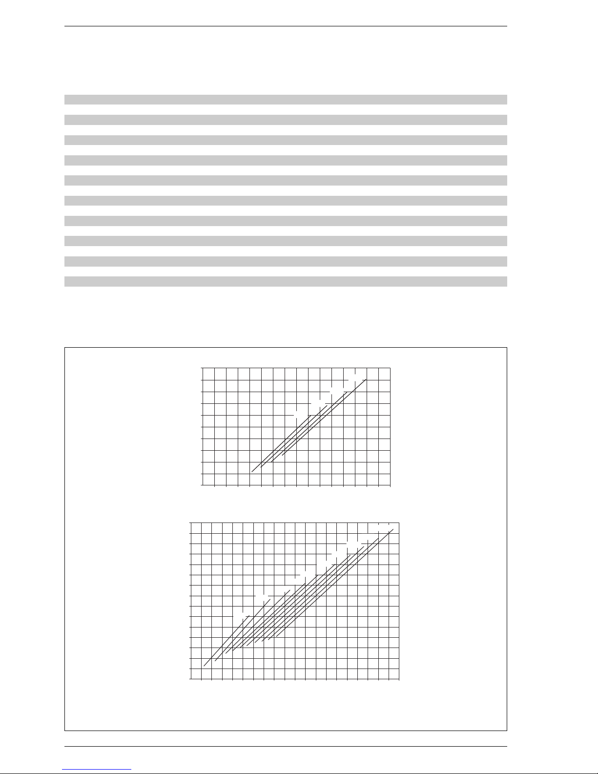
1.4 LOS S OF H EA D
1.3. 2 “2 R/ 2R G T” b oi le r
Fig. 2
NOTE: The losses of head shown in the diagram were obtained with a Δt of 10°C
“1R” boiler
“2R/2R GT” boilers
6789101112131415
Output kW 100.6 123.8 147.1 165.1 179.7 197.7 213.4 230.2 248.8 266.9
kcal/h 86,500 106,500 126,500 142,000 154,500 170,000 183,500 198,000 214,000 229,500
Input kW 113.5 139.1 164.7 184.1 199.7 219.7 237.1 255.8 276.4 296.7
kcal/h 97,600 119,700 141,600 158,300 171,700 188,900 203,900 220,000 237,700 255,200
P (depth) mm 735 835 935 1,035 1,135 1,235 1,335 1,435 1,535 1,635
Sections n° 6 7 8 9 10 11 12 13 14 15
Max. water head bar 5 5 5 5 5 5 5 5 5 5
Wate r content l92107122136151165180194209223
Loss of head
Smoke mbar 0.10 0.15 0.22 0.29 0.24* 0.37* 0.39* 0.42* 0.49* 0.50*
Water (Δt 10°C) mbar 61.0 76.0 85.0 92.0 100.0 1,120 118.0 121.0 125.0 130.0
Comb. chamb. press. mbar – 0.02 – 0.02 – 0.01 – 0.02 – 0.02 – 0.01 – 0.02 0.31 0.35 0.50
Suggested chimney depress.
mbar 0,12 0,17 0,23 0,31 0,26 0,38 0,41 0,73 0,84 1,00
Smokes temperature °C 238 236 234 232 229 224 219 215 211 207
Smokes flow m
3
n/h 105.2 129.2 153.3 171.9 186.9 205.4 221.6 238.9 257.9 276.6
Adjustment range
Heating °C 30÷85 30÷85 30÷85 30÷85 30÷85 30÷85 30÷85 30÷85 30÷85 30÷85
Smoke volume dm
3
83 92 101 110 119 128 138 147 157 167
Weight kg 462 520 578 636 676 734 792 850 908 966
12345678
0
10
20
30
40
50
Portata m3/h
Δp mbar
1R 8
1R 7
1R 6
1R 9
4 5 6 7 8 9 10 11 121314 15 16 17 18 19
0
20
40
60
80
100
Portata m3/h
Δp mbar
2R 6
2R 7
2R 9
2R 8
120
20 21 22 23
140
2R 10
2R 11
2R 12
2R 13
2R 14
2R 15
* Without baf fles
Flow m3/h
Flow m3/h
 Loading...