

Page 1
SIMCOM CONFIDENTIAL FILE
SIMCOM_EVB Kit_User Guide_V1.01
Page 2

Smart Machine Smart Decision
SIMCOM CONFIDENTIAL FILE
Document Title:
Version:
Date:
Status:
Document Control ID:
General Notes
SIMCom offers this information as a service to its customers, to support application and engineering efforts
that use the products designed by SIMCom. The information provided is based upon requirements
specifically provided to SIMCom by the customers. SIMCom has not undertaken any independent search for
additional relevant information, including any information that may be in the customer’s possession.
Furthermore, system validation of this product designed by SIMCom within a larger electronic system
remains the responsibility of the customer or the customer’s system integrator. All specifications supplied
herein are subject to change.
Copyright
This document contains proprietary technical information which is the property of SIMCom Limited.,
copying of this document and giving it to others and the using or communication of the contents thereof, are
forbidden without express authority. Offenders are liable to the payment of damages. All rights reserved in
the event of grant of a patent or the registration of a utility model or design. All specification supplied herein
are subject to change without notice at any time.
Copyright © Shanghai SIMCom Wireless Solutions Ltd. 2016
SIMCOM_EVB Kit_User Guide
1.01
2016-08-17
Release
SIMCOM_EVB Kit_User Guide_V1.01
SIMCOM_EVB Kit_User Guide_V1.01 2 2016-08-17
Page 3

Smart Machine Smart Decision
SIMCOM CONFIDENTIAL FILE
Contents
Contents ..................................................................................................................................................................... 3
Version History .......................................................................................................................................................... 5
1. SIMCOM-EVB Overview ..................................................................................................................................... 6
2. EVB Accessory ...................................................................................................................................................... 8
3. Accessory Interface ................................................................................................................................................ 9
3.1 Power Interface ............................................................................................................................................ 9
3.2 Audio Interface ............................................................................................................................................ 9
3.3 SIM Card Interface ...................................................................................................................................... 9
3.4 USB Interface .............................................................................................................................................. 9
3.5Power Switch .............................................................................................................................................. 10
3.6POWER_ON Button ................................................................................................................................... 10
3.7RF Switch ................................................................................................................................................... 10
3.8 LED Indicator .............................................................................................................................................11
4. Test Interface ....................................................................................................................................................... 12
4.1 Test Point A ................................................................................................................................................ 12
4.2 Test Point B ................................................................................................................................................ 13
4.3 Test Point C ................................................................................................................................................ 14
4.4Test Point D ................................................................................................................................................ 15
4.5Test Point E ................................................................................................................................................. 16
5. Illustration ............................................................................................................................................................ 17
5.1 SIMCom TE installation and uninstallation .............................................................................................. 17
5.2Power on Module:....................................................................................................................................... 17
5.3 Registering Network and Making a Call ................................................................................................... 18
SIMCOM_EVB Kit_User Guide_V1.01 3 2016-08-17
Page 4

Smart Machine Smart Decision
SIMCOM CONFIDENTIAL FILE
Figure Index
FIGURE1: SIMCOM-EVB TOP VIEW ............................................................................................................................. 6
FIGURE2: SIMCOM-EVB BOTTOM VIEW ................................................................................................................... 7
FIGURE 3: EVB ACCESSORY ......................................................................................................................................... 8
FIGURE4: AUDIO INTERFACE ....................................................................................................................................... 9
FIGURE 5: VIRTUALSERIAL PORT ............................................................................................................................. 10
FIGURE 6: TEST INTERFACE OVERVIEW ................................................................................................................. 12
FIGURE 7:TEST POINT A .............................................................................................................................................. 12
FIGURE8: TEST POINT B .............................................................................................................................................. 13
FIGURE9: TEST POINT C .............................................................................................................................................. 14
FIGURE10: TEST POINT D ............................................................................................................................................ 15
FIGURE11: TEST POINT E ............................................................................................................................................ 16
FIGURE12: TE ASSEMBLY ........................................................................................................................................... 17
SIMCOM_EVB Kit_User Guide_V1.01 4 2016-08-17
Page 5

Smart Machine Smart Decision
SIMCOM CONFIDENTIAL FILE
Version History
Data Version Description of change Author
2016-07-12 1.00 Origin shijie.yuan
2016-08-17 1.01
1. Update earphone
2. Add LED indicator for Status
shijie.yuan
SCOPE
This document describes how to use SIMCOM-EVB to do test; user can get useful info about the SIMCOM-EVB
quickly through this document.
This document is subject to change without notice at any time.
SIMCOM_EVB Kit_User Guide_V1.01 5 2016-08-17
Page 6
Smart Machine Smart Decision
SIMCOM CONFIDENTIAL FILE
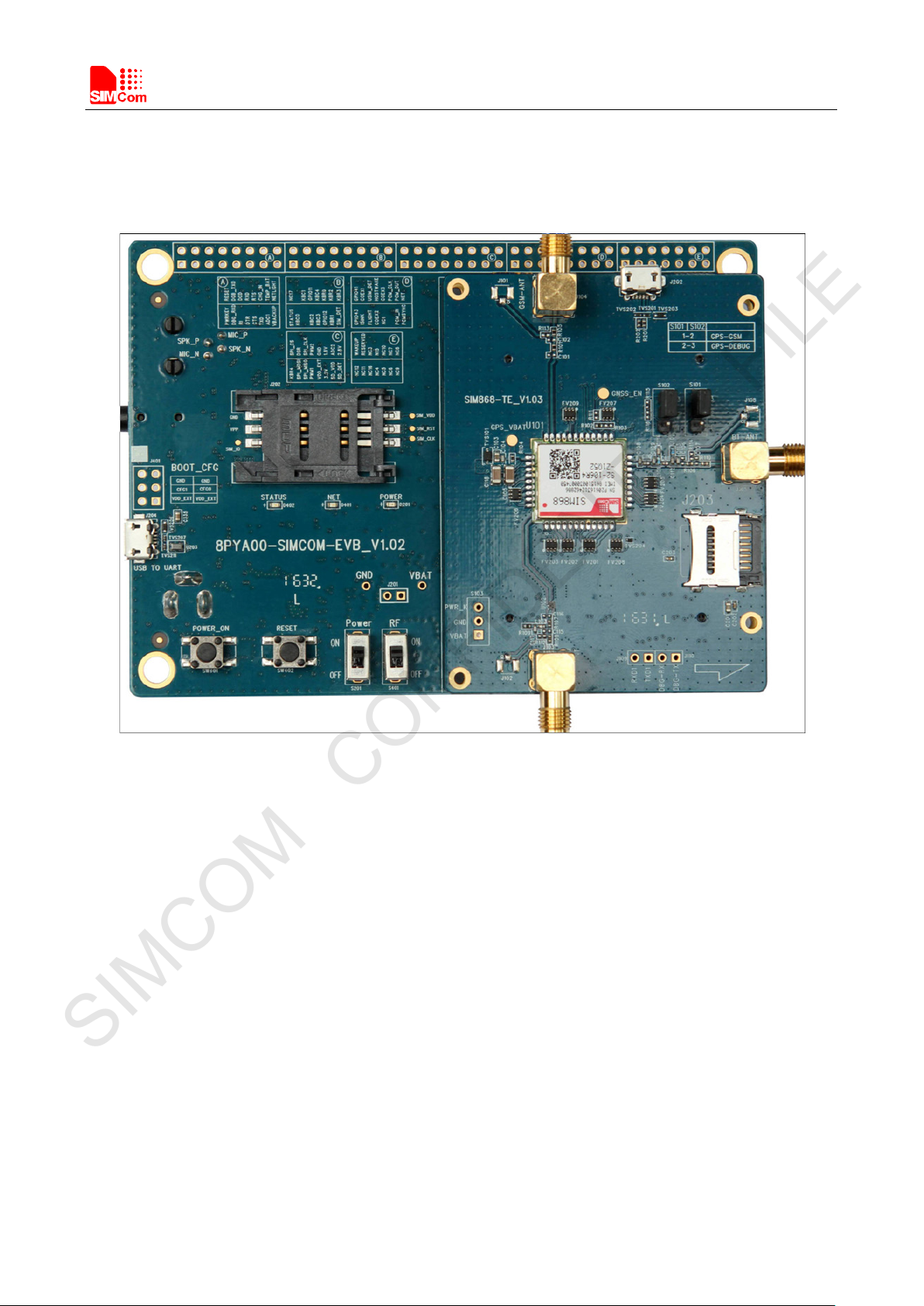
1. SIMCOM-EVB Overview
Figure1: SIMCOM-EVB TOP view
SIMCOM_EVB Kit_User Guide_V1.01 6 2016-08-17
Page 7

Smart Machine Smart Decision
SIMCOM CONFIDENTIAL FILE
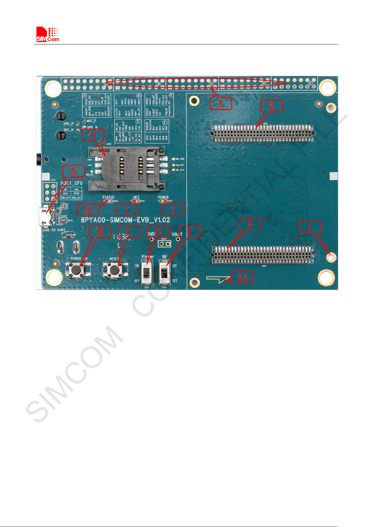
A: USB jack
B: Powerkey
C: Reset
D: Power switch
E: RF switch
F: TE connector
G: TE connector
H: SIMcard holder 1
I: LED indicator for Netlight
J: LED indicator for Power
K: Test Point
L: Studs and nuts
M: mark of TE Module direction
N: LED indicator for Status
O: Handset jack
P: Power jack
Q:SIMcard holder 2
R:Earphone jack
Figure2: SIMCOM-EVB BOTTOM view
SIMCOM_EVB Kit_User Guide_V1.01 7 2016-08-17
Page 8

Smart Machine Smart Decision
SIMCOM CONFIDENTIAL FILE
2. EVB Accessory
A: SIMCOM-EVB
B: 5V DC adapter
C: USB Cable
D:GSM/WCDMA /LTE antenna
Figure 3: EVB Accessory
SIMCOM_EVB Kit_User Guide_V1.01 8 2016-08-17
Page 9
Smart Machine Smart Decision
Pin
Signal
I/O
Description
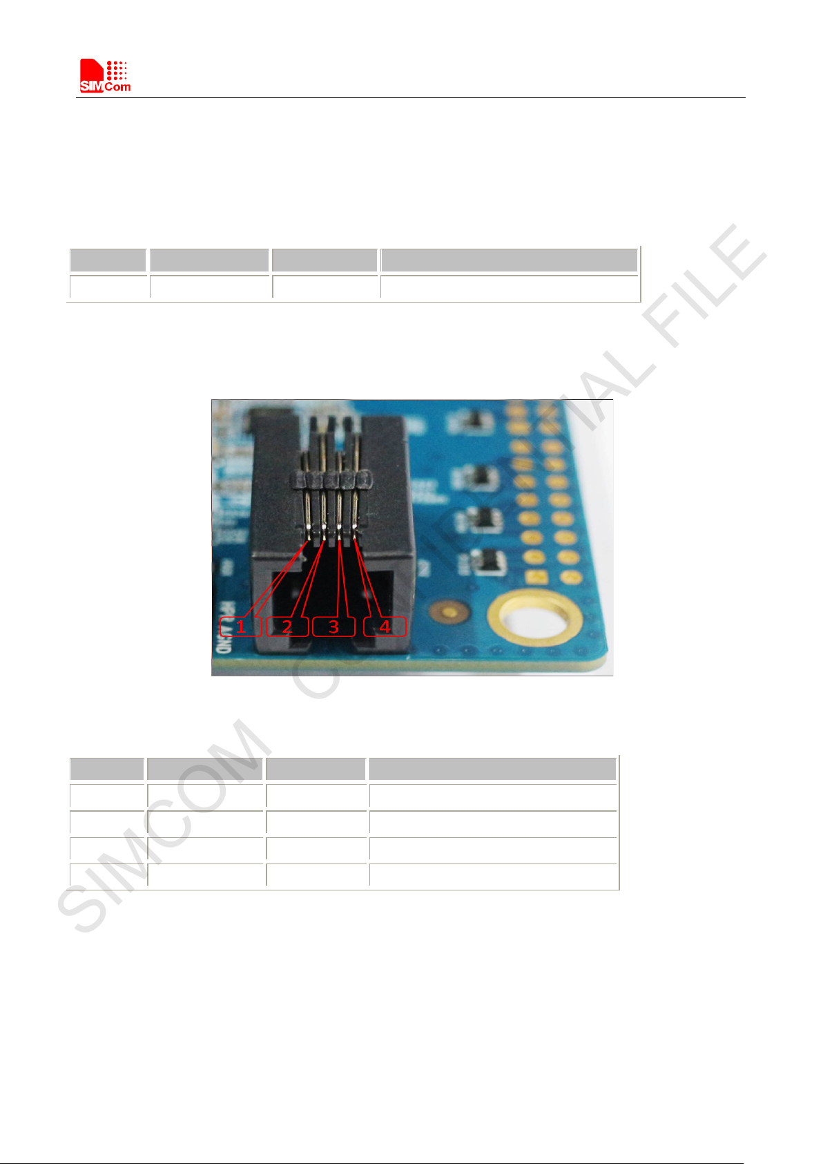
1
MICN
I
Negative microphone input
2
SPKN
O
Negative receiver output
SIMCOM CONFIDENTIAL FILE
3. Accessory Interface
3.1 Power Interface
Pin Signal I/O Description
1 Adapter input I 5V/2.0A DC source input
3.2 Audio Interface
Figure4: Audio Interface
Headset interface:
3 SPKP I Positive receiver output
4 MICP O Positive microphone input
3.3 SIM Card Interface
SIMCard holder 1(J202) is the main holder, SIM2(J203) is for special module which supports dual sim.
3.4 USB Interface
EVB USB interface (A) could be imaged to two virtual ports.
SIMCOM_EVB Kit_User Guide_V1.01 9 2016-08-17
Page 10

Smart Machine Smart Decision
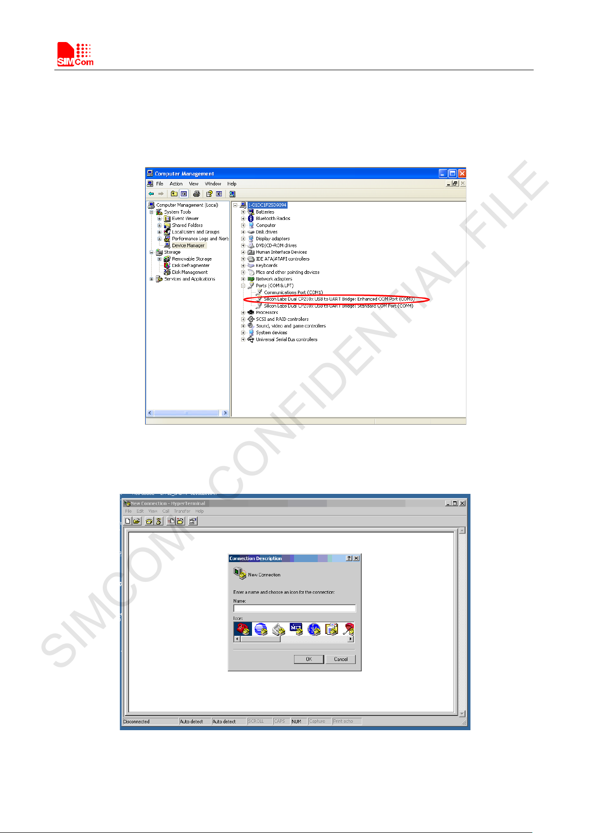
SIMCOM CONFIDENTIAL FILE
Figure 5: Virtualserial port
Enhanced COM port: AT communication
Standard COM port: Debug
CP2105 driver is available here:
http://www.silabs.com/products/interface/usb-bridges/Pages/usb-bridges.aspx
3.5Power Switch
After 5V Adapter inserted ,switch S201 on, then power LED (D201) willbe solid on.
3.6POWER_ON Button
After give power to EVB,press the POWER_ON button for more than 1.5 seconds, the module will be turned on,
the network LED light (D401) will blink.
3.7RF Switch
RF switch (S401) could control module RF on or off. That’s hardware control of flight mode. When RF on, flight
mode is off, when RF switch off, flight mode is on.
SIMCOM_EVB Kit_User Guide_V1.01 10 2016-08-17
Page 11

Smart Machine Smart Decision
Name
Description
STATUS
Bright: Module runs normally
Extinct: System is powered down
SIMCOM CONFIDENTIAL FILE
3.8 LED Indicator
LED light work’s behaviour as below.
D201
D401
D402
Power ON/OFF indicator
NET status indicator Blinking at a certain frequency according various net status
Module status indicator
Bright:EVB Power ON;
Extinct: EVB Power OFF
SIMCOM_EVB Kit_User Guide_V1.01 11 2016-08-17
Page 12

Smart Machine Smart Decision
1
PWRKEY
I
Power on key
2
RESET
I
Reset key
3
DBG_RXD
I
Receive data
10
RTX
I
Request to Send
11
TXD
O
Transmit data
13
ADC1
I
ADC input
SIMCOM CONFIDENTIAL FILE
4. Test Interface
4.1 Test Point A
Figure 6: Test interface overview
Figure 7:Test Point A
Test point A Pin description:
Pin Signal I/O Description
4 DBG_TXD O Transmit data
5 RI O Ring Indicator
6 DCD O Data carrier detection
7 DTR I Data Terminal Ready
8 RXD I Receive data
9 CTS O Clear to Send
12 CHG_IN I Charge in detect
14 TEMP_BAT I Temperature detect
15 VBACKUP P Battery for RTC
16 NETLIGHT O LED indicator for NET Light
SIMCOM_EVB Kit_User Guide_V1.01 12 2016-08-17
Page 13

Smart Machine Smart Decision
Pin
Signal
I/O
Description
1
STATUS
O
Module working on indicate
2
NC17
3
KBC0
I
KEYPAD input
10
KBC4
I
KEYPAD input
13
KBR1
I
KEYPAD input
SIMCOM CONFIDENTIAL FILE
4.2 Test Point B
Test point B Pin description:
Figure8: Test Point B
4
5
6 KBC1 I KEYPAD input
7 KBC2 I KEYPAD input
8 GPIO11 I/O GPIO
9 KBC3 I KEYPAD input
11 GPIO12 I/O GPIO
12 KBR0 I KEYPAD input
14 KBR2 I KEYPAD input
15 SIM1_DET I SIM detect
16 KBR3 I KEYPAD input
SIMCOM_EVB Kit_User Guide_V1.01 13 2016-08-17
Page 14

Smart Machine Smart Decision
Pin
Signal
I/O
Description
2
SPI_CS
O
SPI Chip Select
3
SPI_MOSI
O
SPI Data output
12
1V8
P
1.8V Power
13
SD_VDD
P
Power for SD Card
SIMCOM CONFIDENTIAL FILE
4.3 Test Point C
Test point C Pin description:
Figure9: Test Point C
1 KBR4 I KEYPAD input
4 DSR O Data Set Ready
5 SPI_MISO I SPI Data input
6 SPI_CLK O SPI Clock output
7 PWM1 O PWM output
8 PWM2 O PWM output
9 VDD_EXT P Power output from Module
10 GND P GND
11 3V3 P 3.3V Power
14 ADC2 I ADC input
15 SD_DET I SD detect
16 2.8V P 3.3V
SIMCOM_EVB Kit_User Guide_V1.01 14 2016-08-17
Page 15
Smart Machine Smart Decision
6
SIM2_DET
I
SIM detect
8
HOST_WAKE
O
HOST WAKEUP
9
NC1
SIMCOM CONFIDENTIAL FILE
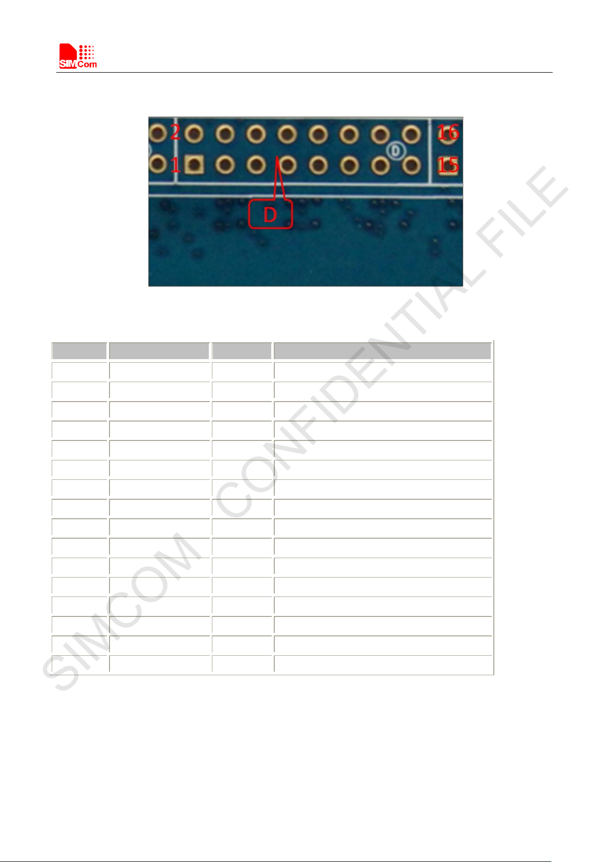
4.4Test Point D
Figure10: Test Point D
Test point D Pin description:
Pin Signal I/O Description
1 GPIO43 I/O GPIO
2 GPIO41 I/O GPIO
3 ISINK AI Ground-referenced current sink.
4 COEX1 O RF synchronizing between Wi-Fi and LTE
5 F LIGHT O Flight mode
7 COEX2 O RF synchronizing between Wi-Fi and LTE
10 COEX3 O RF synchronizing between Wi-Fi and LTE
11
12 PCM_CLK O PCM data bit clock
13 PCM_IN I PCM data input
14 PCM_OUT O PCM data output
15 PCM_SYNC O PCM data frame sync signal
16 NET_STATUS O NET status
SIMCOM_EVB Kit_User Guide_V1.01 15 2016-08-17
Page 16
Smart Machine Smart Decision
6
NC3
8
NC15
9
NC5
SIMCOM CONFIDENTIAL FILE
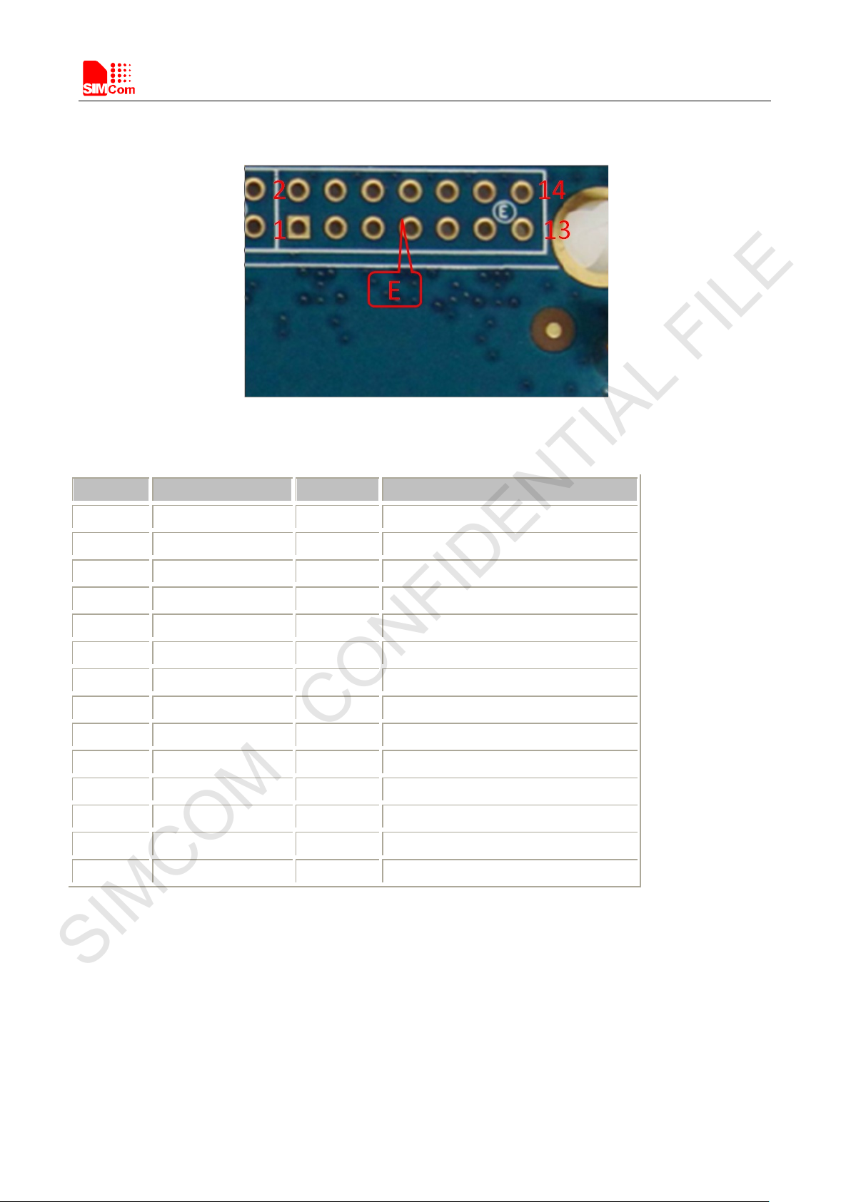
4.5Test Point E
Figure11: Test Point E
Test Point E Pin description:
Pin Signal I/O Description
1 NC12
2 WAKEUP_IN I WAKEUP input
3 NC11
4 RESERVED
5 NC16
7 NC4
10 NC10
11 NC6
12 NC7
13 NC9
14 NC8
Note: please refer to specified TE schematic for test point if there has difference.
SIMCOM_EVB Kit_User Guide_V1.01 16 2016-08-17
Page 17
Smart Machine Smart Decision
SIMCOM CONFIDENTIAL FILE
5. Illustration
5.1 SIMCom TE installation and uninstallation
Figure12: TE assembly
Install TE board:
1) there have four studs on board near connectors. It’s easy to put TE in correct position without making
mistake.
2) take care of TE SMA connector direction;
3) take care of the mark for TE direction on EVB board.
Uninstall and replace TE board:
1) it’s a little hard to remove TE board from EVB connector, because they are connected closely.
2) Take care with power to remove from SMA connector side slowly.
5.2Power on Module:
1) Connect the SIMCOM-TE to the 2x60pins connector on EVB, plug in 5V DC adapter, switch S201 to “ON”
state; keep S401 to “ON” position.
2) Press the POWER_ON button for more than 1.5 second and then release, SIMCOM module power on.After
the module is on, the LED light D402 will be bright ,and the LED light D401will blink at a certain frequency.
Through the state of LED, you can judge registering status of the module. For detailed description, please
refer to SIMCOM HD document.
SIMCOM_EVB Kit_User Guide_V1.01 17 2016-08-17
Page 18
Smart Machine Smart Decision
SIMCOM CONFIDENTIAL FILE
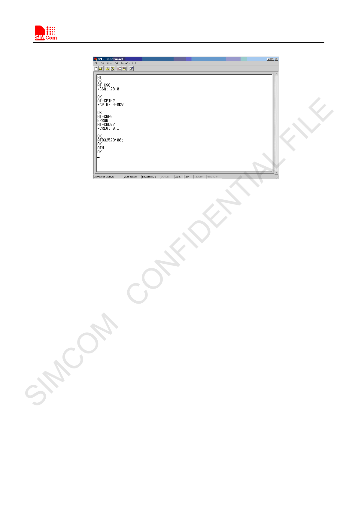
5.3 Registering Network and Making a Call
1) Install antenna to TE board, insert SIM card.
2) Connect the USB cable to the USB jack; launch the Hyper Terminal in computer.
3) Check the serial port number from Device Manager list.
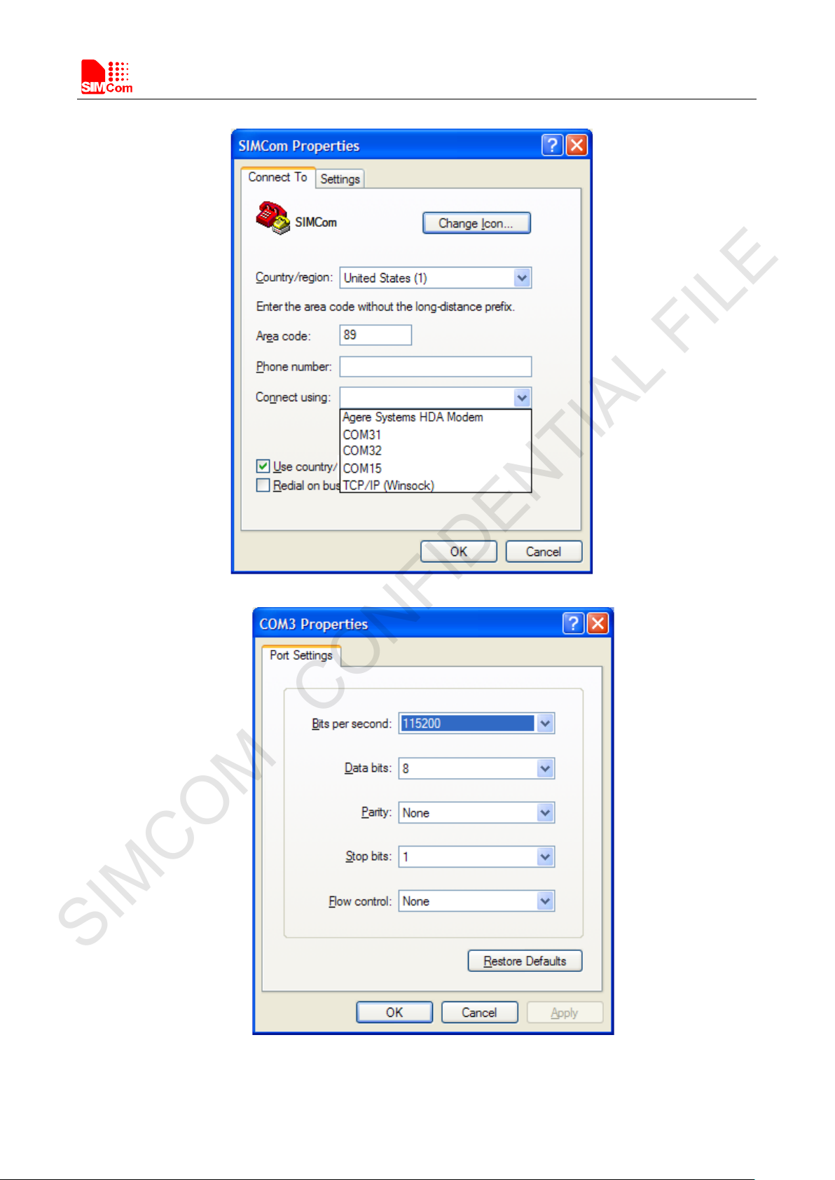
4) Use the Hyper Terminal to make a call from module as following:
a) Launch hyper terminal
b) configure right com port
SIMCOM_EVB Kit_User Guide_V1.01 18 2016-08-17
Page 19
Smart Machine Smart Decision
SIMCOM CONFIDENTIAL FILE
c) configure baudrate
d) Lastly connect the module and make a call.
SIMCOM_EVB Kit_User Guide_V1.01 19 2016-08-17
Page 20
Smart Machine Smart Decision
SIMCOM CONFIDENTIAL FILE
SIMCOM_EVB Kit_User Guide_V1.01 20 2016-08-17
Page 21

Smart Machine Smart Decision
SIMCOM CONFIDENTIAL FILE
Contact us
Shanghai SIMCom Wireless Solutions Ltd.
Address: Building A, SIM Technology Building, No.633, Jinzhong Road, Changning District, Shanghai 200335
Tel: 86-21-32523300
Fax: 86-21-32523020
Email:
Website:www.simcomm2m.com
simcom@sim.com
SIMCOM_EVB Kit_User Guide_V1.01 21 2016-08-17
 Loading...