

Page 1

Benchtop Ionizing Blower
Aerostat® PC2
INSTALLATION AND OPERATING INSTRUCTIONS
Aerostat PC2 5201334 Rev. A
Page 2

TABLE OF CONTENTS
1. SAFETY WARNINGS ...............................................................................................1
2. DESCRIPTION.........................................................................................................2
Product Features ..................................................................................................................2
Performance .........................................................................................................................3
Power Requirements ............................................................................................................4
3. SPECIFICATIONS....................................................................................................5
4. INSTALLATION .......................................................................................................6
Important Safety Information .............................................................................................6
Placement & Mounting .......................................................................................................6
Power Connections ..............................................................................................................8
5. OPERATION ............................................................................................................9
Operating Environment .......................................................................................................9
Controls & LED Indicators .................................................................................................9
Balance ..............................................................................................................................10
Alarms ...............................................................................................................................11
FMS Relay Contact ...........................................................................................................13
Optional Air Filter .............................................................................................................13
6. MAINTENANCE ................................................................................................... 14
Scheduling .........................................................................................................................14
Cleaning ............................................................................................................................14
7. TROUBLESHOOTING .......................................................................................... 16
8. PARTS & ACCESSORIES ...................................................................................... 17
9. WARRANTY ......................................................................................................... 18
Aerostat PC2 5201334 Rev. A
2
Page 3
1. SAFETY WARNINGS
Carefully read the following safety information before installing or operating the
equipment.
Failure to follow these safety warnings could result in damage to your ionization
system and/or voiding the product warranty.
This instruction manual uses symbols to identify dangerous situations as follows:
GENERAL SAFETY
NOTE – Statements identified with NOTE indicate precautions necessary to
avoid potential equipment failure.
CAUTION – Statements identified with CAUTION indicate potential safety
hazards.
WARNING – Statements identified with WARNING indicate potential serious
injury hazards.
PRODUCT SAFETY
NOTE – Do not attempt to operate at voltages other than those specified.
NOTE – Do not allow dust, dirt or debris to block or obstruct air flow inlets or
outlets.
NOTE – This equipment must be correctly installed and properly maintained.
Adhere to the following notes for safe installation and operation:
1. Read instruction manual before installing or operating equipment.
2. Only qualified service personnel are to perform installation and repairs.
3. All equipment must be properly grounded, including the machine frame to
which the equipment is mounted.
4. Turn off input power to unit before connecting or disconnecting other
equipment.
5. Do not operate the system in close proximity to fumes and flammable liquids.
WARNING – Electric Shock Hazard
Electrical installation and repairs must be performed by a skilled electrical
engineer according to the applicable national and local regulations. The
equipment must be properly grounded. Grounding is required to ensure safe
and proper operation and to prevent electrical shocks upon contact.
WARNING – Fire Hazard
Keep the unit dry. Do not operate the unit in flammable or explosive
environments.
Aerostat PC2 5201334 Rev. A
1
Page 4

2. DESCRIPTION
Simco-Ion's Aerostat PC2 is a lightweight, high-performance benchtop ionizer
featuring a three-speed fan for varying applications. The Aerostat PC2 small
footprint design occupies much less workspace than traditional blowers. With its
universal mounting stand, the Aerostat PC2 can be used at virtually any location
to control static charge where contamination, ESD, material-handling problems, or
microprocessor lock-up occurs. The Aerostat PC2 is also light enough to be easily
mounted above workstations for space-constrained benchtop areas.
The Aerostat PC2 uses the Simco-Ion patented "Micropulse" Technology to meet
the performance, particle cleanliness, and low maintenance requirements necessary
to maximize production yield in many applications.
The Aerostat PC2 is available with an optional heater to reduce the effects of wind
chill.
This manual covers the installation, operation, and maintenance of the Aerostat PC2
Ionizing Blower.
Product Features
The Aerostat PC2 has the following unique features and benefits:
• Patented "Micropulse" Technology with high-efficiency output that provides
long periods between maintenance cycles
• Internal closed-loop feedback control maintains balance at +/-10V or better
• LEDs and audible alarm (if ordered) for both high voltage fault and fan
status
• Employs a high efficiency, multi-speed fan to produce a strong ionized
airflow
• Built-in brush cleaner for easy, periodic cleaning of emitters
• Universal AC input accepts all IEC power cords
• A relay contact is provided for monitoring of ionizer's operational status via
the end user's facility monitoring system (FMS)
• An optional heater for reducing the wind chill effect (an optional feature
available at the at the time of purchase)
Aerostat PC2 5201334 Rev. A
2
Page 5
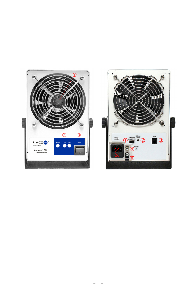
Front Panel Rear Panel
1. Emitter Point Cleaner
2. Status Lights: Power, Fan, Fault
3. Power Switch
1. Fan Speed Switch
2. Balance Adjust
3. FMS Output
4. Ground
5. Fuse Holder
6. Power Cord Clamp
7. Power Cord Inlet
Figure 1. Aerostat PC2 Front-panel
(non-heater version)
Figure 2. Aerostat PC2 Rear Panel
Performance
The Model Aerostat PC2 is factory adjusted to meet the specifications described
below:
• 2.0 seconds or less @ 12” (30 cm)
• 3.0 seconds or less @ 24” (60 cm)
• 5.0 seconds or less @ 36” (91 cm)
• 8.0 seconds or less @ 48” (122 cm)
These decay times are directly in line with the center of the fan, ±1000V to 100V.
Measurements were taken at the stated distance at high fan speed using a charged
plate monitor in accordance with ESD Association Ionization Standard ANSI/ESD
STM3.1-2015.
Discharge times may be different when tested within your operating environment.
Aerostat PC2 5201334 Rev. A
3
Page 6

The PC2 will maintain a balance around zero of ±10V or less in a humiditycontrolled environment. Performance in extreme environments may vary. When
using the optional fan filter, the unit's performance will be reduced between 10-40%
depending upon the speed of the blower and the distance to the target.
Power Requirements
The Aerostat PC2 requires different input voltages depending on heater or without
heater.
• 100-230 VAC, 50/60 Hz, 0.2A,10W max (no heater)
• 100-120 VAC, 50/60 Hz, 2.0A, 250W max (with heater)
• 220-230 VAC, 50/60 Hz, 1.0A, 250W max (with heater)
CAUTION – The use of improper input voltage may result in poor performance
or damage to the unit. Damage caused to the power supply from operation at
levels outside the specified limits will void the warranty.
Aerostat PC2 5201334 Rev. A
4
Page 7

3. SPECIFICATIONS
100-230 VAC, 50/60 Hz, 0.2A, 10W max, fuse 0.63A 250V Slo-Blo
Input Voltage
Discharge
Balance 0 ±10V (typ)
Coverage 1'W x 4'L (30 x 122 cm) area
Ion Emission Micropulse AC Ionization
Emitters Stainless Steel emitter points
Controls POWER ON/OFF, FAN SPEED control LOW/MEDIUM/HIGH
Indicators Green POWER on, red FAN alarm, red FAULT alarm LEDs
Audible Alarm Fault and Fan stall (optional)
FMS Connector RJ-9 4P/4C receptacle, relay contact rated +/-24 VDC @ 0.2A max
Air Volume 129 cfm (high fan speed)
Air Velocity
Audible Noise 61 dB (low fan speed), 64 dB (high fan speed) measured 2’ in front of blower
Ozone <0.05 ppm measured @ 1’ (305 mm) in front of blower
Operating Env. Temperature 50-95°F (10-35°C); humidity 30-60% RH, non-condensing
Mounting Stand Powder-coated aluminum with skid resistant rubber feet
Enclosure Powder-coated aluminum
Air Filter 30 ppi open cell foam lter with bracket (optional)
Dimensions 9.1”H x 6.8”W x 3.3”D (23.1H x 17.3W x 8.4D cm) with stand
Weight 2.8 lbs (1.25 kg) with stand with skid resistant rubber feet
Warranty Two-year limited warranty
120V Heater Option: 100-120 VAC, 50/60 Hz, 2.0A, 250W, fuse 2.5A 250V Slo-Blo
220V Heater Option: 220-230 VAC, 50/60 Hz, 1.0A, 250W, fuse 1.6A 250V Slo-Blo
1
2.0 sec @ 1' (30 cm) (1000-100V high fan speed)
2
370 fpm @ 12", 240 fpm @ 24", 164 fpm @ 36", 120 fpm @ 48" (high fan)
Certications
1. Tested in accordance with ANSI/ESD STM3.1-2015.
2. High fan speed; velocity in fpm measured at centerline of the air stream.
Aerostat PC2 5201334 Rev. A
5
Page 8

4. INSTALLATION
Important Safety Information
Carefully read the following safety information before installing or operating the
equipment. Failure to follow these safety warnings could damage to your ionization
system and/or void the product warranty.
• The use of improper input voltage may result in poor performance or
damage to the ionizer will also void the warranty.
• This product is supplied with a 3-prong grounding plug, which must be
inserted in an appropriate, properly wired, and grounded receptacle. Do
not defeat the electrical ground. For safety, the use of extension cords is not
recommended.
• Do not use this Blower in an explosive environment. Poorly maintained
Ionizers could produce miniscule electric arcs along the emitter which
may cause detonation in an explosive environment. Read Section 4 Power
Connections and Section 5 Operating Environment before applying power
to the unit.
• Avoid personal injury or damage to the equipment, do not perform any
maintenance other than that contained in these instructions. Do not insert
anything within the intake or outlet grills.
• There are no user-replaceable parts for this blower other than the power
fuse. Any unauthorized service will void the warranty and may result in
additional repair charges. Contact your local Simco-Ion representative if the
blower requires service or repair.
• For indoor use only in a non-condensing environment. This product is not
intended for use in tropical climate regions or at altitudes above 2000m.
• Before performing any recommended maintenance, ensure the unit is
powered off and unplugged.
Placement & Mounting
Placement
The PC2 should be positioned to cover as much of the target area as possible with
the ionized air stream. Keep at least a 6 inches clearance between walls or any objects
and the rear of the PC2 to allow for adequate air intake.
The Aerostat PC2 should be placed approximately 1 to 4 feet (0.3 to 1.2m) from
neutralized objects or the critical work area. Discharge times are longer the further
away the PC2 is placed from the target area. Testing by Simco-Ion has shown that
the PC2 can ionize a target area further than 4 feet from the blower.
Aerostat PC2 5201334 Rev. A
6
Page 9
Operate the Aerostat PC2 ionizer for an initial 24 hours in application area before
any performance measurements are conducted.
Mounting
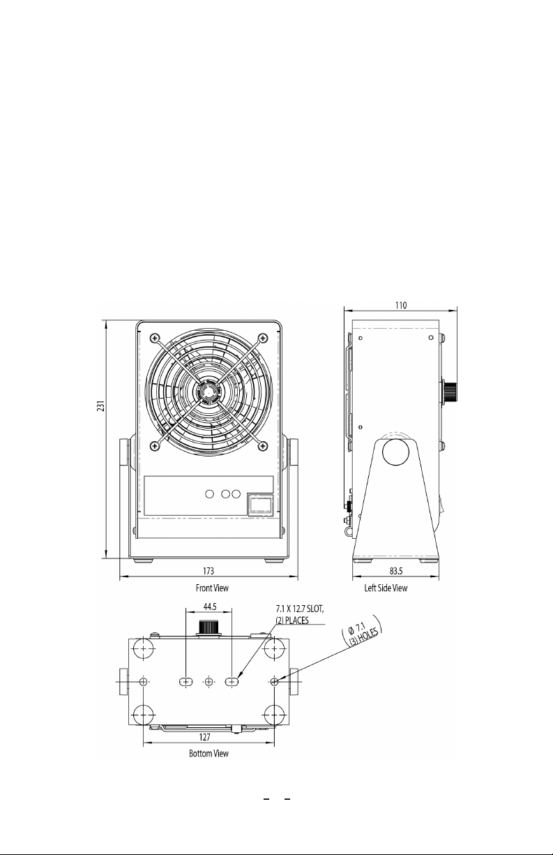
The Aerostat PC2 comes with a mounting stand pre-assembled to the Blower. The
mounting stand is designed for a free or fixed position on a tabletop or workbench
and mounting to a fixed surface. Holes in the base of the stand are provided for
securing the PC2 to a fixed location using 1/4" (or M6) threaded hardware (not
provided). Self-adhesive skid-resistant rubber feet are supplied with the Blower and
can be installed on the bottom of the stand by the end-user.
Once the Aerostat PC2 is secured to a surface, the mounting stand can be adjusted
and locked to the desired position. Loosen, but do not completely remove, the knobs
on each side of the blower. Tilt the PC2 to the desired position, so the PC2 ionized
airstream is aimed directly at the target with no intervening grounded objects and
re-tighten the knobs to lock the PC2 into place.
Figure 3. Aerostat PC2 Mounting (dimensions shown are in mm)
Aerostat PC2 5201334 Rev. A
7
Page 10
Power Connections
The PC2 accepts universal AC input (100-230 VAC 50/60 Hz single phase, no
heater option only). The PC2 is available with different line cords to meet the
main power connection plug requirements in many world areas. The PC2 must be
grounded for safe and proper operation.
Connect the supplied power cord to an appropriate 3-terminal grounded AC power
receptacle.
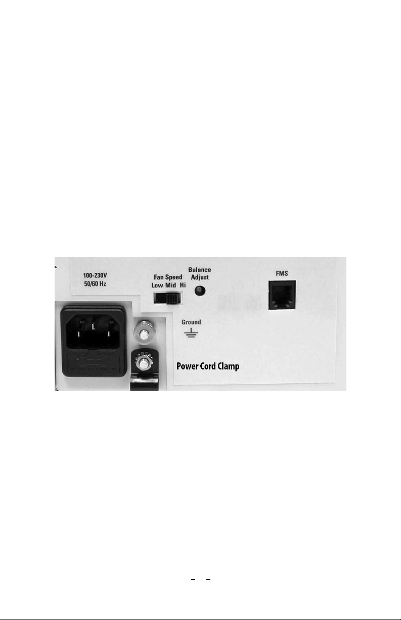
If the PC2 Blower is installed in an environment that is electrically noisy area, an
additional ground connection can be made to the Blower using the convenience
ground terminal located on the rear panel of the blower.
A cord clamp is supplied with the blower. Use this cord clamp to prevent unwanted
disconnection of the power cord or protect against the accidental loosening of the
power cord due to vibration.
After connecting the power cord to the power inlet connector, fit the power cord
through the cord clamp and secure the clamp to the rear chassis panel with the
supplied #6 nut.
Figure 4. Chassis Ground Stud and Power Cord Clamp
Aerostat PC2 5201334 Rev. A
8
Page 11
5. OPERATION
Operating Environment
WARNING – Electric Shock Hazard
Do not insert anything within the intake or outlet grills. Electric shock may
result.
The output side of the Blower should not be tilted more than 10 degrees
upward above the vertical plain blowing across a work surface/table. This is to
prevent any object from penetrating the unit from the output side—electric
shock may result.
Operate the Model Aerostat PC2 in an environment where the relative
humidity is 30-60% (non-condensing). The operating temperature range for
the Blower is 50-95°F (10-35°C).
The Model Aerostat PC2 will conform to stated performance specifications when
used in an environment that meets the cleanliness limits defined by ISO 14644-1
Class 6 (Fed Std. 209E Class 1000) and if it is serviced according to an appropriate
maintenance schedule.
• For indoor use only in a non-condensing environment
• Do not use this Blower in an explosive environment
• The PC2 Blower is not intended for Tropical Climate regions
• The PC2 Blower is not intended for use at altitudes above 2000m
Controls & LED Indicators
Power
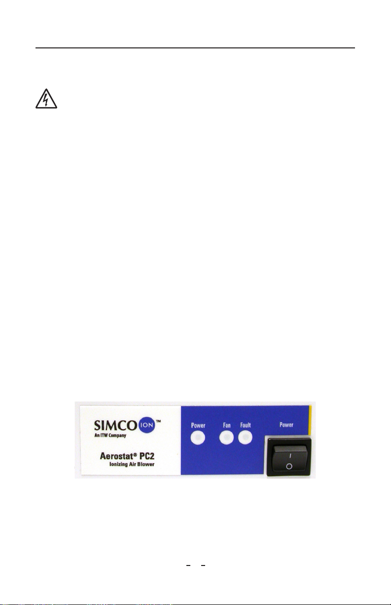
Turn on the PC2 by setting the "POWER" switch on the front panel to the ON
position ("I"). The green LED "Power" indicator light on the front panel will light,
and the fan will startup.
Figure 5a. Power on LED and Power on Switch (non-heater version)
Aerostat PC2 5201334 Rev. A
9
Page 12
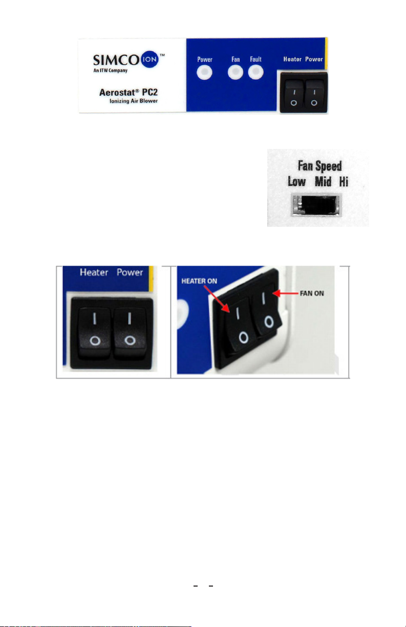
Figure 5b. Power on LED and Power on Switch (heater version)
Fan Speed Adjustment
The fan speed may be adjusted using the Fan Speed
slide switch on the back of the Aerostat PC2. The PC2
fan can be set to Low, Medium or High airflow.
Heater ("H" Model Only)
Turn the heater ON by setting the "HEATER" rocker
switch to the on ("I") position. NOTE: The heater will
only operate when the fan is on.
Figure 7. Switches
The heater provides about a 2-3°C rise in the temperature of the ionized air at the
face of the Blower, which is just enough to counter the effects of wind chill. The
PC2 heater is not meant to act as a space heater.
Figure 6. Fan Speed Adjustment
Switch
If the HEATER switch is turned on and the FAN switch is turned off the heater
automatically stops. The PC2 heater is protected with a thermal cutout device that
will deactivate the heater in the case of overheating, such as inadequate airflow due
to a failed fan.
Balance
The Aerostat PC2 has a balance adjust control for setting the initial balance of the
Blower. The internal feedback control system will then maintain the balance of the
PC2 to +/-10V around the initial balance set point.
Aerostat PC2 5201334 Rev. A
10
Page 13

The Aerostat PC2 leaves the factory with the Balance Adjust Control set to meet
performance specifications during the final factory test. For optimal performance, it
is recommended that the PC2 balance setting be checked and adjusted (if required)
by the end-user prior to using the Blower. A Charged Plate Monitor (CPM) with a
standard 6" x 6" plate, such as the Simco-Ion Model 280A, is required to monitor
the balance of the ionizer during the balance adjustment procedure.
NOTE – It is recommended that the PC2 be allowed to run and acclimatize for
an initial 12-24 hours in an environment comparable to the application area
before any performance measurements are conducted.
1. Set the PC2 fan to the desired speed.
2. Place a Charged Plate Monitor at a distance of about 12" (300 mm) directly in
front of the blower with the CPM plate positioned in the ionized air stream.
Turn on the CPM and set it for balance monitoring. Observe the balance
reading displayed by the CPM.
3. Use a trimpot tool or small flat blade screwdriver to adjust the "Balance" control
on the rear panel of the PC2. Turning the balance adjust control clockwise will
make the balance voltage more positive. Turning the control counterclockwise
will make the balance more negative.
The PC2 should be adjusted so that the CPM displays a balance of about 0V +/-5V.
NOTE – For PC2 with heater option, it is important to re-balance the unit by
adjusting the trimpot clockwise or counterclockwise when the heater is turned
ON or OFF to achieve the specification performance.
Simco-Ion recommends using the built-in brush emitter point cleaner daily
for optimum balance performance. This will ensure that the Aerostat PC2
provides the best decay and balance performance to your target area.
The Aerostat PC2 Blower should be OFF when using the emitter point
cleaner. Do not clean the emitter points while the Blower is operating.
Alarms
An alarm condition may be caused by any of the following:
• No power to the fan unit
• The fan in locked-rotor condition or fan failed
• Failed high voltage power supply
• Extremely dirty emitter points (possible)
If you have ordered the Aerostat PC2 with an audible alarm, the audible alarm will
sound upon any alarm condition.
Aerostat PC2 5201334 Rev. A
11
Page 14
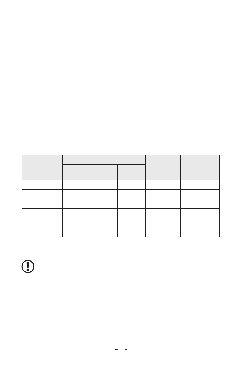
There are 2 red LED indicators located on the front panel:
1. FAN: When constantly lit, the fan is not rotating properly (stalled fan). This
alarm will clear itself if the fan can resume normal operation.
2. FAU LT:
• Constantly lit: No high voltage on the emitters. A constant FAULT indicator
can be cleared by correcting the fault condition and cycling the power to the
Blower OFF and ON again.
• Blinking: High voltage is ON, but ± ionization is not controlled. A blinking
FAULT indicator will clear if the ionization control condition is corrected.
(Suggestion: clean the emitter points using the built-in brush).
When either the FAN stalls or FAULT-HV FAILS conditions occur, the Blower will
try to recover. The Blower will wait about 5 sec, then clear all the alarms (clearing the
LEDs and the FMS relay) and turn on the high voltage again. If the fault condition
still exists, the retry cycle will repeat up to two times. If the Blower fails to recover
after 3 attempts, the high voltage will remain off, and the Blower will remain in an
alarm state until the input to the Blower is cycled OFF/ON.
LED Status Indicators
POWER
Condition
Power OFF OFF OFF OFF Open OFF
Power ON, All Ok ON OFF OFF Closed ON
HV Fault ON OFF ON Open OFF
FAN Fault ON ON OFF Open OFF
Low 24 VDC Blinking OFF OFF Closed ON
HV Drive Error ON OFF Blinking Open ON
(Green)
FAN
(Red)
FAULT
(Red)
FMS Relay
Output
Ionization
Voltage State
Table 1. Alarms and LED Status Indicators
NOTE – The alarm of the Aerostat PC2 is not designed or calibrated to
function as a maintenance alarm. If the emitter points are allowed to become
extremely dirty, there is the possibility that the Ionization fault alarm will start
to turn ON intermittently. If this happens, clean the emitter points following
the procedures described in Section 6 Cleaning.
Aerostat PC2 5201334 Rev. A
12
Page 15
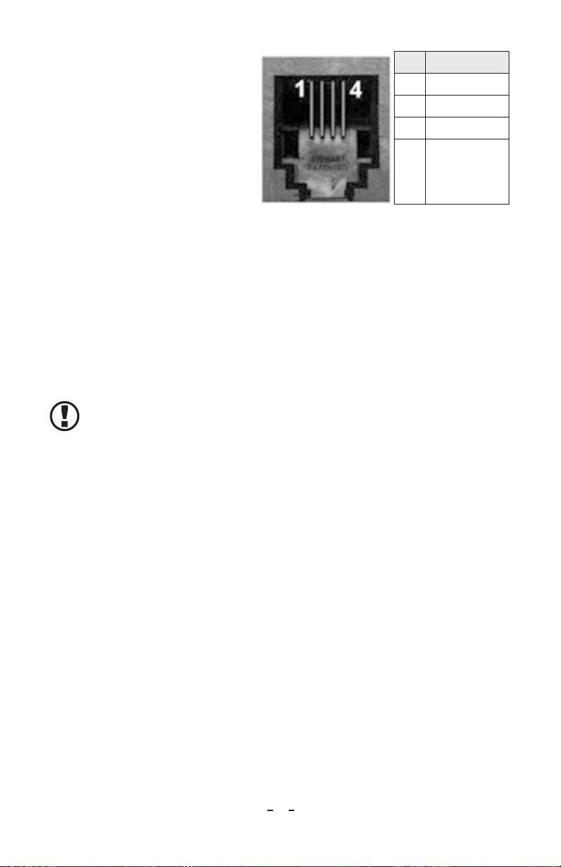
FMS Relay Contact
The Aerostat PC2 provides an
optoisolated relay contact for
indicating alarm status to your
process equipment or facility
monitoring system (FMS). The
relay contact is rated for a maximum
of +/-24 VDC, 0.20A
• Relay Open - Blower is in
alarm or Power is OFF
• Relay Closed - Normal
Blower operation
Table 2. FMS Output Connection RJ-9
Pin Function
1 Ground
2 Relay Contact 2
3 Relay Contact 1
4 No Connection
Optional Air Filter
An optional air filter kit is available for extremely dirty or dusty environments. The
air filter kit includes a 30 ppi polyurethane open-cell foam air filter that mounts
over the rear fan guard using a stamped metal frame and separate sheet metal screws.
No disassembly of the original rear fan guard is required. The foam air filter can be
cleaned and reused. Simco-Ion also offers a replacement filter pack (see Section 8
Parts and Accessories).
NOTE – When using the optional fan filter, the unit's performance will be
reduced between 10-40% depending upon the speed of the Blower and the
distance to the target.
Aerostat PC2 5201334 Rev. A
13
Page 16

6. MAINTENANCE
Scheduling
The balance of the Model Aerostat PC2 is designed to be maintained by internal
circuitry and, after initial setup, should not need further adjustment by the end-user.
The PC2 requires little or no user maintenance other than regular cleaning of the
emitter points with the built-in brush emitter cleaner or more extensive cleaning of
the emitter points, case, and fan.
NOTE – Simco-Ion recommends using the built-in brush emitter point cleaner
daily. This will ensure that the Aerostat PC2 provides the best decay and
balance voltage performance to your target area.
The Aerostat PC2 blower should be OFF when using the emitter point
cleaner. Do not clean the emitter points while the Blower is operating.
Maintenance schedules will vary depending on environmental conditions. Therefore,
determine a schedule that meets the requirements of your application and
environment.
CAUTION – Before performing any of the following cleanings, be sure the
Aerostat PC2 is powered OFF and unplugged.
Avoid personal injury or damage to the equipment, do not perform any
maintenance other than that contained in these instructions.
There are no user-serviceable parts inside this Blower other than the input
power fuse. Any unauthorized service will void the warranty and may result
in additional repair charges.
Cleaning
Built-in Emitter Point Cleaning Brush
Use the built-in emitter point cleaning brush for routine daily cleaning of the emitter
points.
CAUTION – Avoid personal injury or damage to the equipment, do not
perform any maintenance other than these instructions.
Before performing any of the following cleanings, be sure the Model Aerostat
PC2 is powered off and unplugged.
DO NOT ATTEMPT ANY MAINTENANCE OPERATIONS TO
THE BLOWER UNLESS THE UNIT IS SWITCHED OFF AND
DISCONNECTED FROM AC POWER.
Turn OFF the PC2 and disconnect the power cord from the rear of the unit.
With the PC2 turned OFF, routine emitter cleaning can be accomplished by
manually rotating the knob on the front of the fan grill in a clockwise direction
Aerostat PC2 5201334 Rev. A
14
Page 17
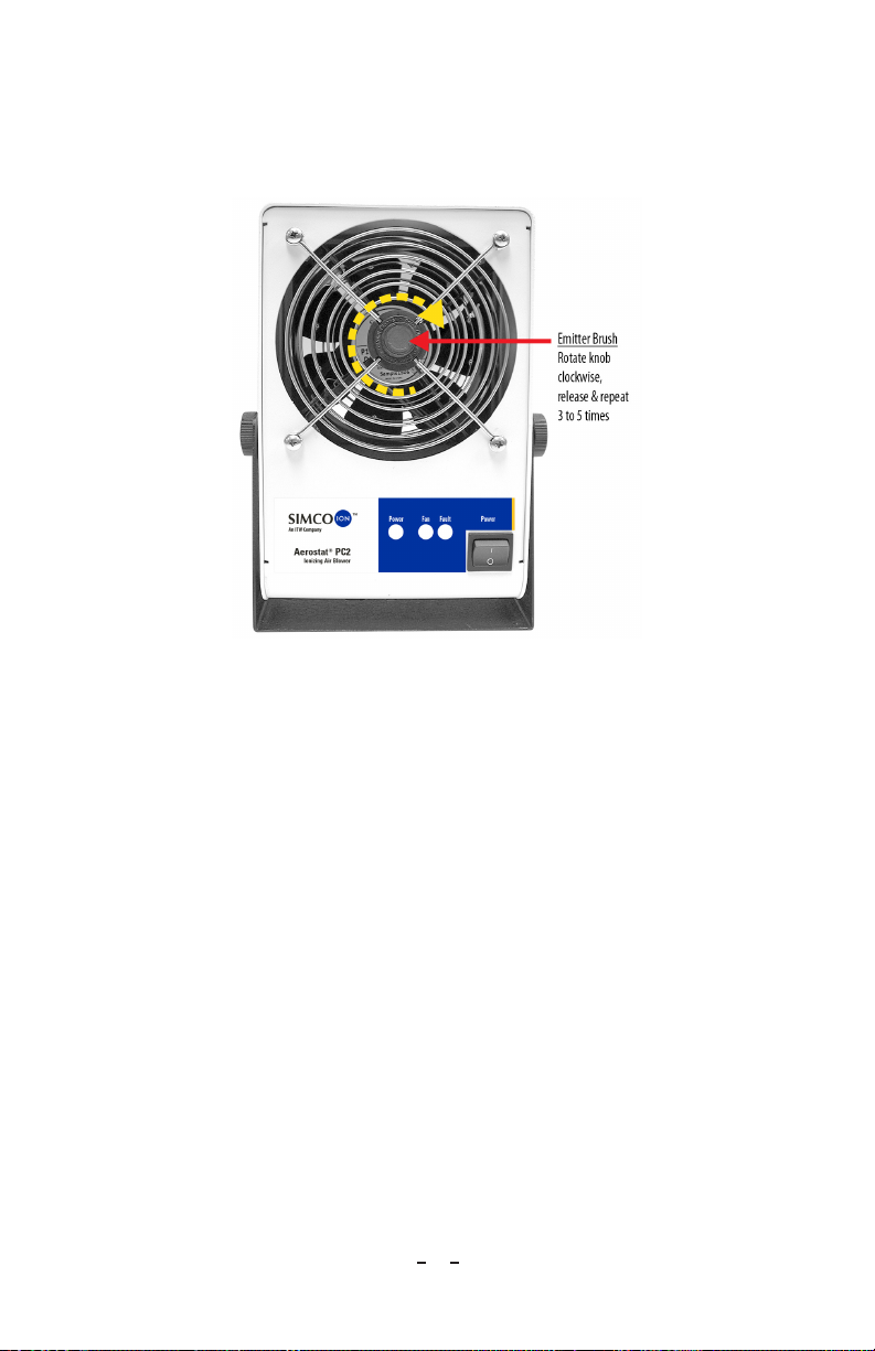
(about one full rotation) to sweep the internal brush over the tips of the emitter
points. At the end of the clockwise rotation, release the knob and allow the brush
to spring back to its resting position. Repeat this brushing operation 3 to 5 times to
ensure maximum cleaning of the emitter point tips.
Figure 8. Manual Emitter Point Cleaning
Comprehensive Cleaning
Recommended cleaning materials for comprehensive cleaning:
• Lint-free cleaning cloths
• Lint-free cloth swabs (polyester cloth is recommended)
• Cleaning solution of 50% IPA (electronic-grade isopropanol alcohol)/50%
de-ionized water
• Clean dry air (CDA)
The fan guards on the front and rear of the PC2 should be kept clean to prevent any
airflow restriction. They can be cleaned with a soft brush, vacuum cleaner, or blown
off with compressed clean, dry air.
Use clean dry compressed (CDA) air to clean dust or dirt from the inside of the unit.
After cleaning, reconnect the power cord to the unit and turn on the PC2. Allow
the PC2 to run for at least five minutes before using it to ionize your target area.
Chassis Cleaning
Thoroughly wipe down the PC2 chassis to remove any accumulated dirt. Moisten a
lint-free cloth with a 50% diluted IPA solution. Change the cloth frequently to make
sure the dirt is completely lifted.
Aerostat PC2 5201334 Rev. A
15
Page 18
7. TROUBLESHOOTING
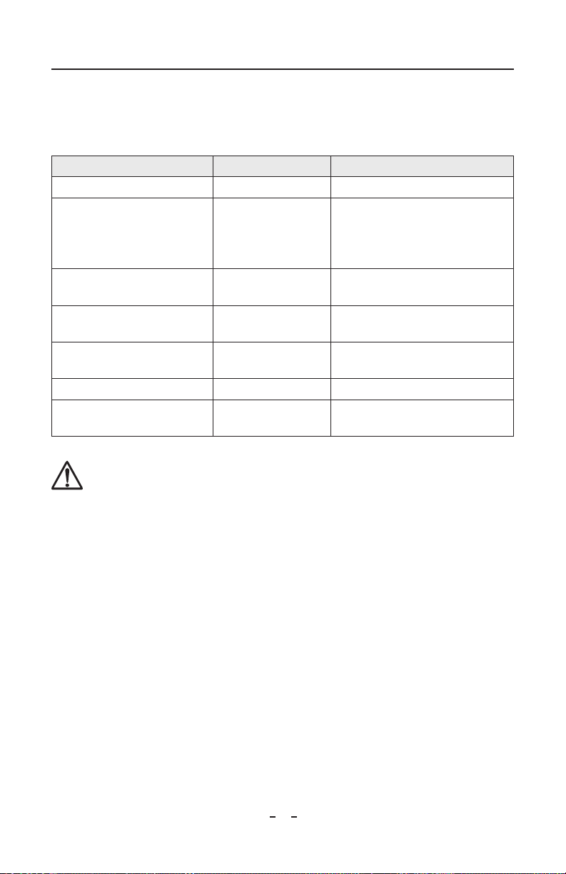
The table below provides a quick troubleshooting reference for the Aerostat PC2.
If the solutions listed do not remedy the problem, contact Simco-Ion Customer
Service at [email protected].
Problem Possible Cause Solution
Fan is noisy or slow Fan is obstructed Check fan guards for any obstructions
Poor power
Fan does not operate
Offset balance is >10V
Decay times are too long
Fault Alarm Blinks
intermittently
FAN Alarm is on continuously Fan has stopped Check fan guards for any obstructions
Fault Alarm is on continuously
connection or fan is
obstructed
Emitter points are
dirty
Emitter points are
dirty
Emitter points are
dirty
Possible HV failure or
fan has stopped
CAUTION – Turn OFF the Model PC2 and disconnect it from power before
attempting to access the fuse drawer.
Check power cords and connections
Check fan guards for obstructions
Check inlet fuse (see below)
Clean the emitter points
Clean the emitter points
Clean the emitter points
Contact Simco-Ion for service
Replace the fuse only with an identically rated part. If replacing the fuse does not
restore the unit to operation, leave the unit turned OFF and disconnected from
power. Contact Simco-Ion technical support for additional information.
• 100-230 VAC, 50/60 Hz, 0.2A,10W max (no heater); fuse =0.63A SLO
• 100-120 VAC, 50/60 Hz, 2.0A, 250W max (with heater); fuse = 2.5A SLO
• 220-230 VAC, 50/60 Hz, 1.0A, 250W max (with heater); fuse = 1.6A SLO
Aerostat PC2 5201334 Rev. A
16
Page 19
8. PARTS & ACCESSORIES
Contact Simco-Ion Customer Service at [email protected] for more
information about these replacement parts and accessories.
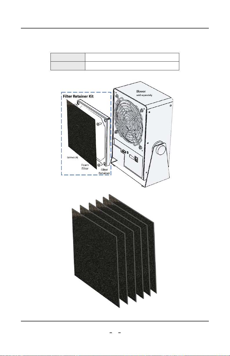
33-6501-01 Aerostat PC2 Air Filter Kit
33-6004-01 Aerostat PC2 Replacement Air Filters (6 pack)
P/N 33-6501-01
P/N 33-6004-01
9. WARRANTY
Aerostat PC2 5201334 Rev. A
17
Page 20

This product has been carefully tested at the factory and is warranted to be free
from any defects in materials or workmanship. Simco-Ion will, under this warranty,
repair or replace any equipment that proves, upon our examination, to have become
defective within one year from the date of purchase.
The equipment being returned under warranty should be shipped by the purchaser
to Simco-Ion, 2257 North Penn Road, Hatfield PA 19440, transportation prepaid
and insured for its replacement cost. Prior to returning any goods for any reason,
contact Simco-Ion Customer Service at (215) 822-6401 for a Return Authorization
Number. This number must accompany all returned items.
This warranty does not apply when the equipment has been tampered with, misused,
improperly installed, altered, has received damage through abuse, carelessness,
accident, connected to improper line voltage, or has been serviced anyone other than
an authorized factory representative.
The warranty does not apply when Simco-Ion parts and equipment have been
energized by other than the appropriate Simco-Ion power supply or generator,
or when a Simco-Ion power supply or generator has been used to energize other
than Simco-Ion parts and equipment. Simco-Ion makes no warranty, expressed or
implied, nor accepts any obligation, liabilities, or responsibility in connection with
the use of this product other than the repair or replacement of parts stated herein.
Aerostat PC2 5201334 Rev. A
18
Page 21

Simco-Ion
2257 North Penn Road
Hatfield, PA 19440
(215) 822-6401
(800) 203-3419
www.simco-ion.com
© 2022 Simco-Ion Printed in the U.S.A.
Aerostat PC2
5201334 Rev. A
 Loading...