

Page 1
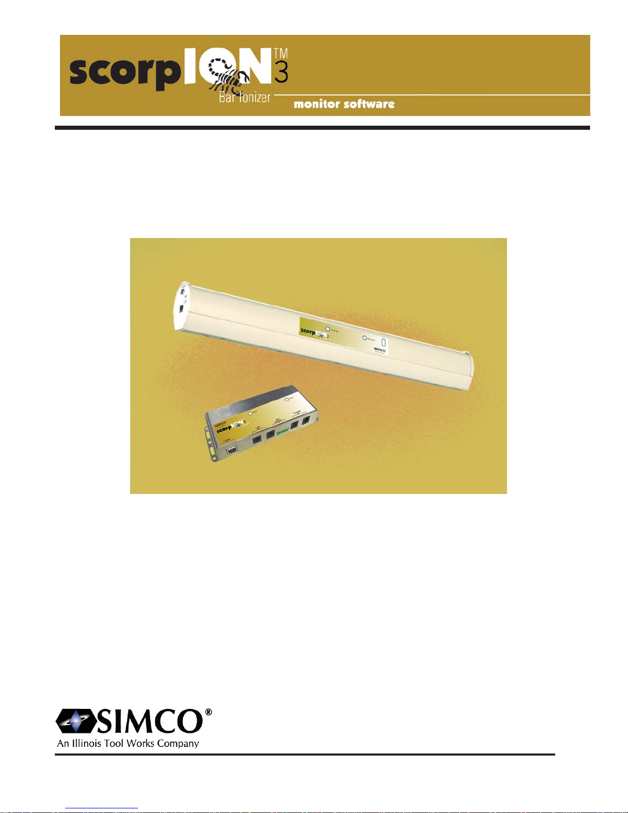
INSTRUCTIONS
Operation/Maintenance
Simco Ionization for Electronics Manufacture
Publication 5200943, June 2007
2257 N Penn Rd - Hatfield , PA 19440
215-997-0590 - 1-800-538-0750 (in USA)
Email: [email protected]
Page 2

Simco Ionization for Electronics Manufacture 1 Publication 5200943
Page 3

Simco Ionization for Electronics Manufacture Publication 5200943
Section 1 Introduction
4
Section 2 scorpION3 CI Computer Interface
6
2.1 Description 6
2.2 Specifications 6
2.3 Systems Connections 7
2.4 Ethernet Equipped Models 8
2.5 Internal Address Configuration 8
2.6 The scorpION3 Bus and Connections 9
2.7 The RS-485 Bus and Connections 10
2.8 The User Interface and Connections 10
Section 3 Account Types
12
3.1 User Account 12
3.2 Manager Account 12
3.3 Interface Layout 13
Sectio
n 4 Status Panel
14
4.1 Active Errors 14
4.2 History 14
4.3 Legend 14
4.4 Causes Tab 15
4.5 Solution Tab 15
Section 5 History Tab
16
Section 6 Graphic Panel
18
6.1 Full Screen Graphic View 18
Section 7 Error Logging
20
7.1 Daily Error Logging 20
7.2 Active Error Logging 20
7.3 An Example with Error Conditions 21
7.4 Context Sensitive Error Analysis 22
7.5 Expanded Historic View 23
Table of Content
2
Page 4

Section 8 Bar Modification
24
8.1 Custom Grouping History 24
8.2 Modifying a Controller 25
8.3 Programming a Bar 26
8.4 Diagnosing a Bar 28
8.5 Changing the Role of Bar 29
8.6 Changing the Address of Bar 30
Notes
Data Log
Simco Ionization for Electronics Manufacture Publication 5200943
3
32
33
Page 5

Simco Ionization for Electronics Manufacture Publication 5200943
Features Include:
• Tool Interface Integration
• "Peak Reduction" Technology
• Bi-directional Intelligent MMI
• Full Digital Platform
• Active Monitor and Control
• SiC Emitters (US and International patents pending)
The scorpION3 ionizing bar utilizes SIMCO's innovative and
effective microcontroller intelligent ionization technology.
The system provides rapid neutralization of static charges
over a localized work area or in a mini environment. It is the
most flexible and efficient system available, capable of eliminating electrostatic discharge (ESD) and preventing electrostatic attraction (ESA) of particles to surfaces.
Section 1
Introduction
Introduction
4
SECTION 1- Introduction
Page 6

Simco Ionization for Electronics Manufacture Publication 5200943
5
Page 7
Simco Ionization for Electronics Manufacture Publication 5200943
SSCCOORRPP
ION3 CI Computer Interface
2.1 Description
The scorpION3 CI (Computer Interface) was designed to allow multiple ion bar systems to be connected
and controlled from a single personal computer through dedicated hardware. This connection allows ion
bar performance and settings to be monitored, configured and diagnosed. The computer interface continuously polls the condition, settings and diagnostic information of connected ion bars. Using this device
allows the construction of a scorpION3 network consisting of multiple CI units each with multiple ion bars
connected.
Each CI supports up to 10 connected ion bars on a dedicated scorpION3 communication / power distribution bus. Multiple CI's can be 'networked' via a true RS-485 communication bus used to supplying data
to a PC. Ethernet capable models convert the RS-485 bus to Ethernet allowing
connection of multiple systems via a single IP address. This architecture allows calibration and monitoring
of scorpION3 based systems. The computer interface also provides a user interface, which provides an
auxiliary power input and relay contacts for system level fault detection.
scorpION3 CI Features:
- Ethernet option
- Two RS485 interconnect bus connections
- 24VDC input, with power indicator
- Two scorpION3 bus connections
- Stainless steel case with mounting options
6
SECTION 2
scorpION3 CI
Computer Interface
SECTION 2- scorpION2 CI Computer Interface
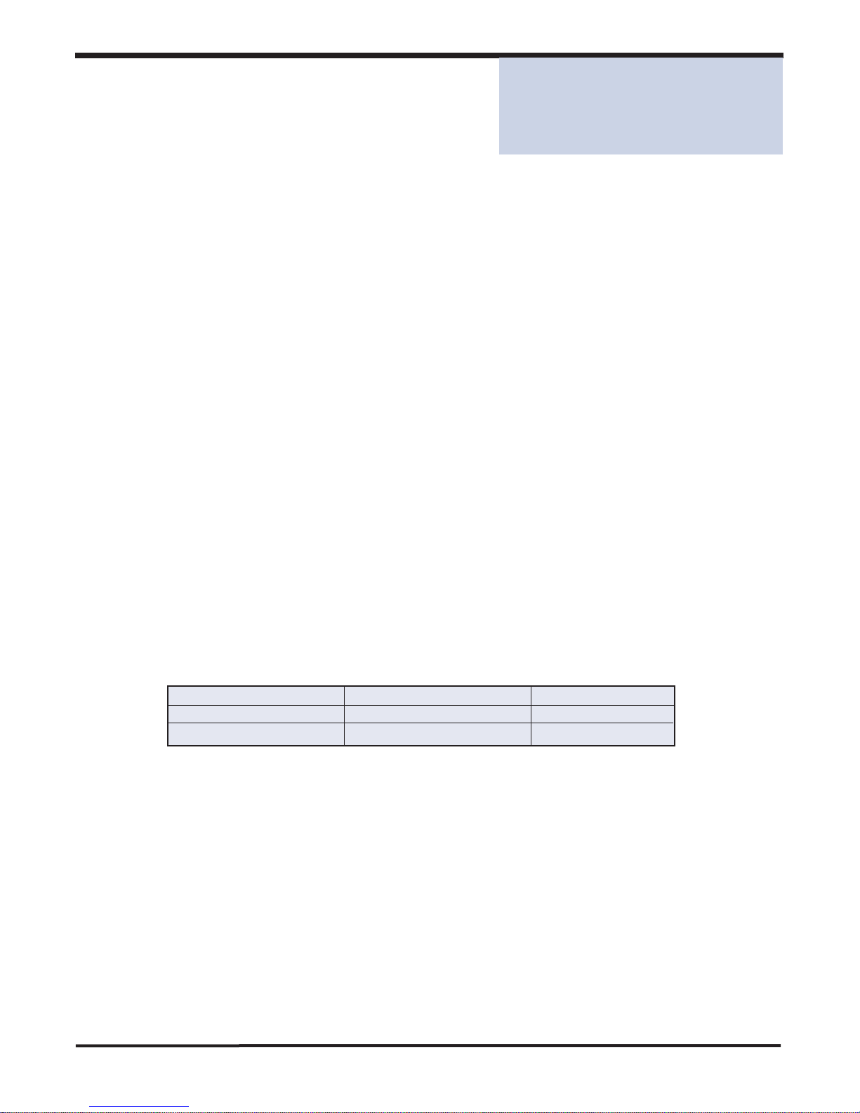
2.2 Specifications:
Unit Part Number: without Ethernet with Ethernet
without Software 5051411 5051412
with Software 5051413 5051414
Power:
24 VDC, 100 mA
Power may be input at the scorpION3 BUS connector (from the scorpION3
bar system) or at the USER INTERFACE connector (see connections sections
of instructions).
scorpION3 Bus:
RJ-11 modular connector x 2
User Interface:
Terminal socket block. Plug-in connector supplied with unit. (Weidmuller P.N.
1792890000)
RS-4485 Bus
RJ-11 modular connector x 2
Ethernet: (optional)
RJ-45 modular connector x 1
Ind
icators:
Power - green LED
Fault - red LED
Enclosure:
Stainless Steel
Weight:
0.64 kg (1.4 lbs)
Mounting:
User supplied M3 or M4 screws (#6 or #8)
Page 8
Ethernet
RS485 BUS
scorpION2 BUS
2.3 System Connections
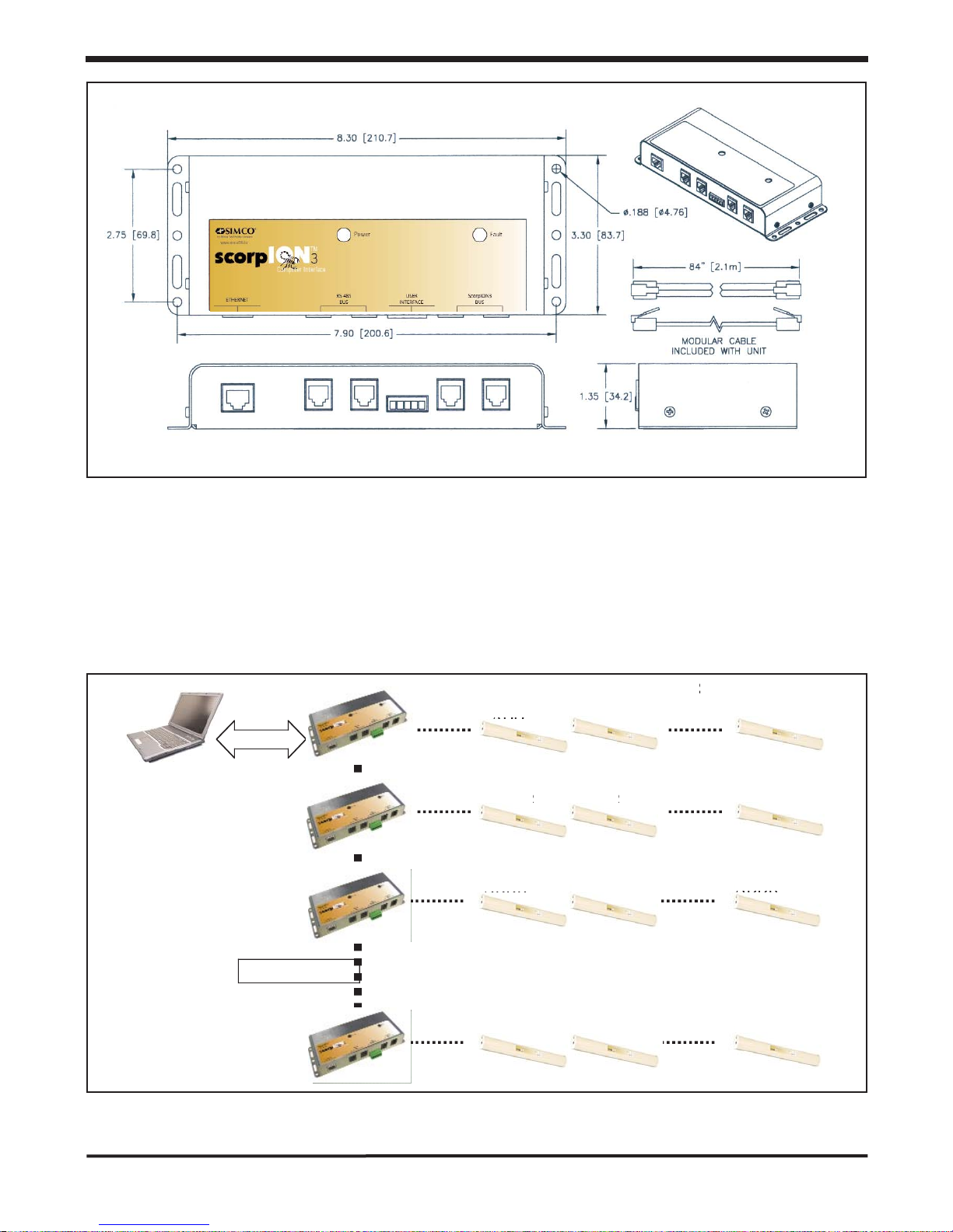
The following figure depicts connections typical to a system with multiple CI units and multiple ion
bars. Connections of scorpION3 bars to the CI are made using the scorpION3 bus. Connections
between scorpION3 CI units are made using the RS-485 bus. Connection to the PC is via
Ethernet.
ADDR
ADDR
ADDR
ADDR
ADDR
ADDR
ADDR
ADDR
ADDR
ADDR
ADDR
ADDR
scorpION2 Computer Interface
Simco Ionization for Electronics Manufacture Publication 5200943
7
SECTION 2- scorpION2 CI Computer Interface
3
Page 9

Simco Ionization for Electronics Manufacture Publication 5200943
2.4 Ethernet Equipped Models
Ethernet equipped models of the scorpION3 CI convert RS-485 to Ethernet directly by using an
embedded device server (EDS). The EDS reliably converts the RS-485 to Ethernet using a single IP
address. Utilities from the EDS configure the PC to use a directly assigned virtual COM port that
remaps the serial port drive to the IP address. In most cases this configuration can be easily
achieved following the quick installation guide. This information as well as detailed user guides can
be located on the CD provided with the hardware.
The Network Enable Administrator runs on Windows based systems, allowing a broadcast search
for EDS devices to be performed. This utility finds EDS's based on their MAC addresses and allows
the assignment of IP addresses. It may be necessary to obtain an IP address for this assignment
from administrators of the network. Options for the COM assignment allow a 'virtual' COM port to
be configured using the mapping functions. After configuration the PC based hardware will use this
virtual COM port to communicate with the scorpION3 system and the PC will automatically retain
this configuration.
By entering the IP address of the EDS directly into the address line of a web browser such as
Internet Explorer, the EDS Web console can be accessed. Many of the same parameters can be
adjusted from the Web console. COM port configuration must have the following settings:
The Ethernet connection on the computer interface is clearly label and follows standard pin out
configurations for Ethernet.
2.5 Internal Address Configuration
A dipswitch internal to the scorpION3 CI is used to configure the address. In installations where
multiple CI units will be connected back to a single PC, each CI must have a unique address. The
dipswitch has 8 positions but switch 1-4 only are used to configure the address. The address equals
the binary number configured by the switches. The following table explains the configuration of
switches 1-4, where 0=off and 1=on, the PC based software subsequently refers to the CI units by
letter.
MOXA NE-4110A CONFIGURATION
PARAMETER
SETTING
Baud Rate
9600
Data Bits
8
Stop Bits
1
Parity
None
Flow Control
None
FIFO
Enable
Interface
RS485 4 Wire
Operation Mode
Real COM Mode
TCP Alive Check Time
99
Max Connection
4
8
SECTION 2- scorpION2 CI Computer Interface
Page 10
Simco Ionization for Electronics Manufacture Publication 5200943
SWITCH SETTINGS (1-4)
ADDRESS
SOFTWARE LABEL
0000
0
A
0001
1
B
0010
2
C
0011
3
D
0100
4
E
ETC….
2.6 The scorpION3 Bus and Connections
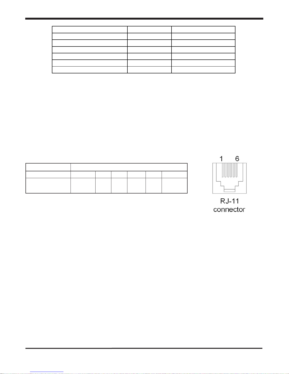
The scorpION3 bus provides power and communication lines to connected scorpION3 bars. Two
RJ-11 style connectors on the CI provide the ability to connect and power ion bars with this bus.
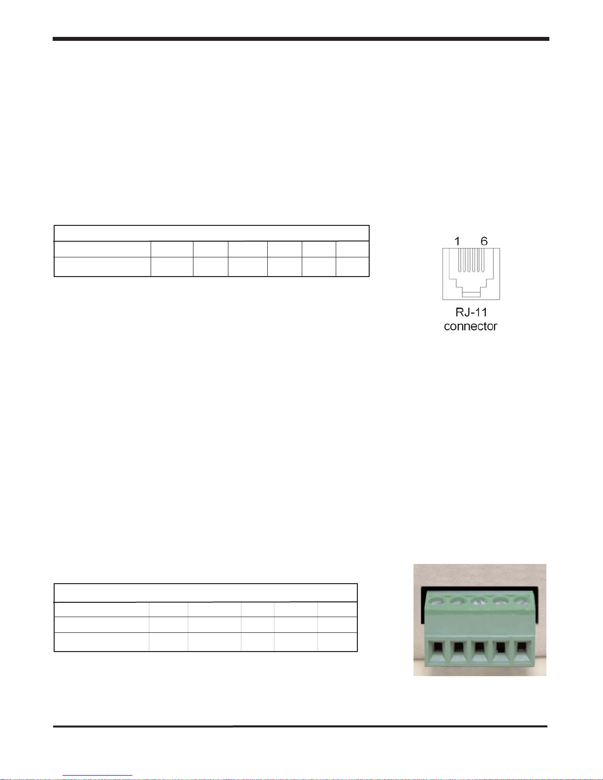
For some installations 24 VDC power can be supplied via the RJ-11 modular connector. Connect
pins 1 & 6 to the +24 volt supply voltage and connect pins 3 & 4 to ground (ground serving as the
return for the supply voltage), see table below. Users connecting to the scorpION3 in this way
should be ready to supply 200mA per ion bar connected and about 100mA for the CI. Note that
the scorpION3 CI is internally fused to protect the user's power supply during this type of setup.
Connections or grounding of the other pins (2 & 4) on the modular connector is not permitted and
may result in malfunction or damage to the system.
scorpION2 bus (N.C. = no connection permitted)
PIN NUMBER 1 2 3 4 5 6
CONNECTION +24VDC N.C. GND GND N.C. +24VDC
+/-10%
Because of the connection scheme used on the scorpION3 bus there is no need to be concerned
with the orientation of interconnection wiring. Cables that are 'flipped' or 'straight' will function identically.
For installations of up to 3 ion bars and a CI, Simco's AC adapter can be utilized. Install all ion
bars and interconnect wiring before applying power. Plug the adapter power cord into a grounded
electrical outlet of 100 to 240 VAC, 50 or 60 HZ. Connect the adapter to the scorpION3 CI and
to the ion bars with modular cables, power will automatically be distributed to the other ion bars
on the 'chain'. The scorpION3 bar has no on/off switch so application of the 24VDC to the unit
will turn it on, and ionization will begin. The adapter and wiring can be located as desired by the
user.
9
SECTION 2- scorpION2 CI Computer Interface
Page 11
Simco Ionization for Electronics Manufacture Publication 5200943
Note: a CI that is powered this way will provide power to ion bars that are connected to it via the
modular connector, and in this configuration the SIMCO adapter can power a maximum of 3 ion
bars.
2.7 The RS-4485 Bus and Connections
The RS-485 bus is a 4 wire, full duplex RS-485 connection. Two connections on the CI are provided for connections to this bus. This bus is used specifically for interconnection of multiple CI units
back to an Ethernet enabled CI. With this construction a single IP address can collect data from
multiple scorpION3 systems. Note that there is no power distribution via these bus connections, so
each CI in the systems must be powered independently.
RS-485 bus
PIN NUMBER 1 2 3 4 5 6
CONNECTION TX+ TX- GND GND RX+ RX-
Cabling that interconnects multiple CI units must be of the 'flipped' or 'parallel' construction, where
by pin 1 is connected to pin 1 on the next connection, etc. This configuration connects all wires in
parallel with one another.
2.8 The User Interface and Connections
The User Interface provides a terminal strip for supplying power to a scorpION3 system. Wiring
connections are made to stripped wires, using clamping screw. This permits direct connection of
the CI and ion bars to existing power in tool or mini-environment applications. The specific pin
outs are provided below. Power supplied to pins 1 and 2 should conform to the following: pin 1
must be earth ground; pin 2 should be 24VDC+/10%. Users who provide power to the system in
this way should budget 200mA per scorpION3 bar and 100mA for the CI itself. The CI has an
internal fuse in series with the power distribution to the ion bars; this protects the power supply due
to wiring (24V) short circuits.
User Interface
PIN NUMBER 1 2 3 4 5
CONNECTION GND +24VDC NC COM NO
+/-10%
10
1 2 3 4 5
SECTION 2- scorpION2 CI Computer Interface
Page 12

Simco Ionization for Electronics Manufacture Publication 5200943
The User Interface also provides a relay contact output that toggles based on fault conditions. The
normal relay positions are indicated in the table above. The CI detects status and conditions from
all connected ion bars. On a fault condition from any ion bar in the system the relay is activated,
changing the state of the relay relative to the common. The fault relay has a contact rating of 30V
at 1A maximum; this should not be exceeded as damage to the unit may result.
11
SECTION 2- scorpION2 CI Computer Interface
Page 13
Account Types
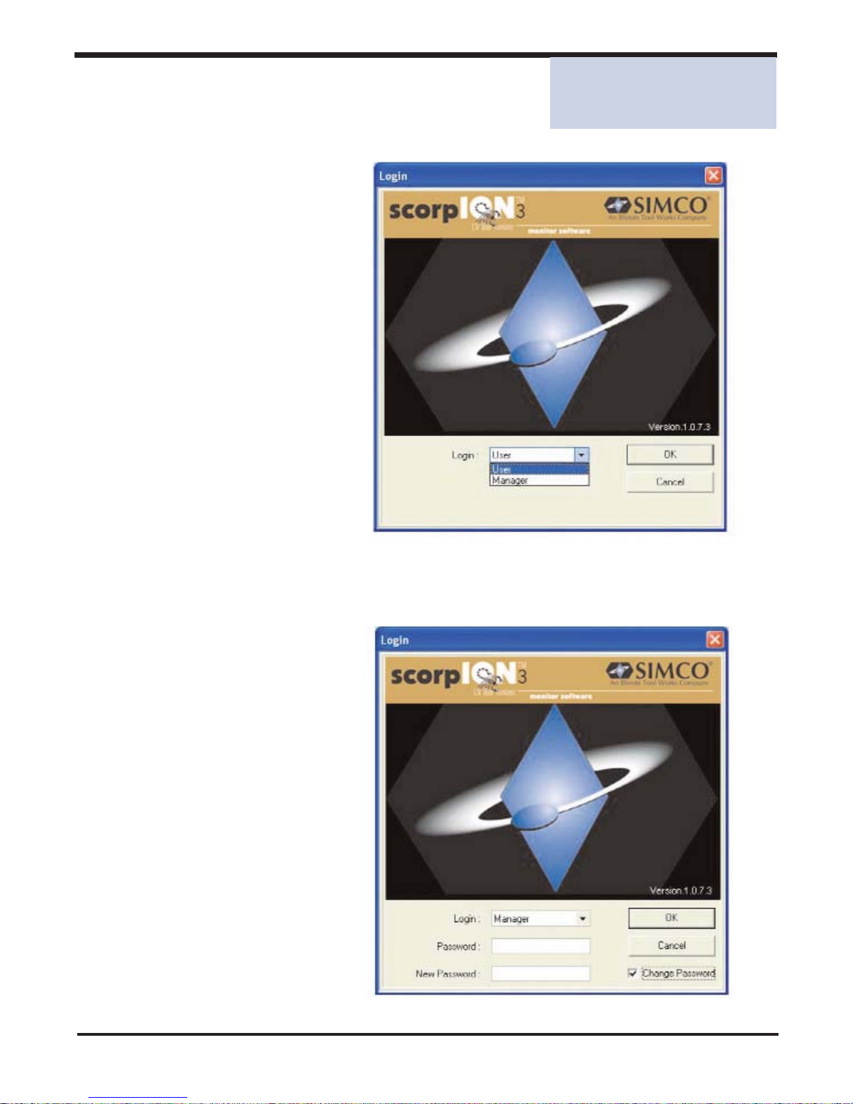
Before an operator can use the
scorpION3 Monitoring System they
need to login. You may login to the
GEMINI Profile Monitoring System in
two ways, as a User or Manager.
3.1 User Account
As a User an operator can:
Monitor the scorpION3 system.
Review both active and corrected
error conditions.
Login without using a password.
3.2 Manager Account
As a
Manager
an operator can:
• Do everything a User can.
• Edit a Controller's location.
• Modify the frequency of
Preventive Maintenance.
• Update the date of last
Preventive Maintenance.
• Modify the frequency of
System Calibration.
• Update the date of last
System Calibration.
• Change the manager login
password.
Simco Ionization for Electronics Manufacture 12 Publication 5200943
SECTION 3
Account Types
SECTION 3 - Account Types
Page 14
Simco Ionization for Electronics Manufacture Publication 5200943
3.3 Interface Layout
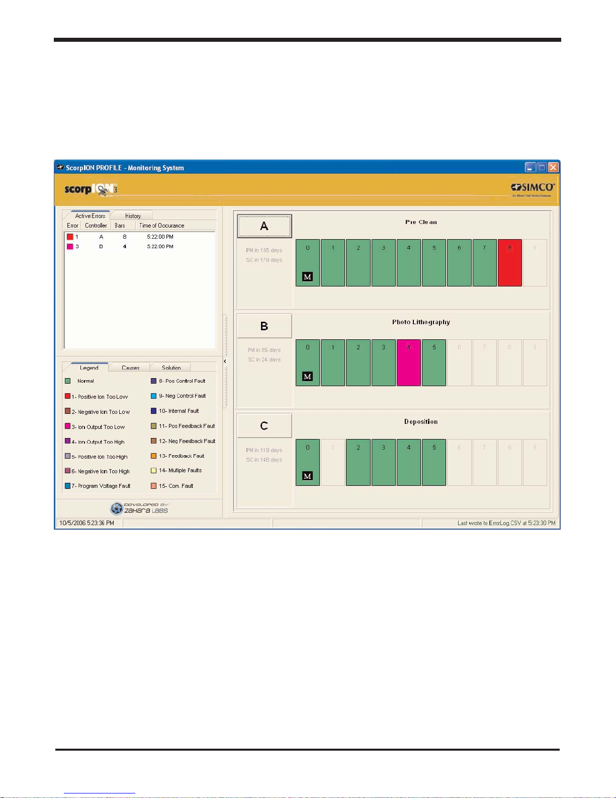
The scorpION3 monitor software is laid out in two primary areas:
Status Panel
and the
Graphic Panel
; separated by a Horizontal divider. A status bar at the bottom
of the screen displays the current date and time, two status areas display the time the Historic Error
log was written to, and when the Active Error log was written to.
The above system is composed of 3 controllers A, B, and C correspondingly having 9, 6, and 5
emitters each. Preventive Maintenance for controller A is due in 135 days and System Calibration is
due in 179 days.
Currently there are two active errors in the Active Errors list. The ErrorLog.csv was last updated at
5:23:30 PM.
13
SECTION 3 - Account Types
Page 15
Simco Ionization for Electronics Manufacture Publication 5200943
Status Panel
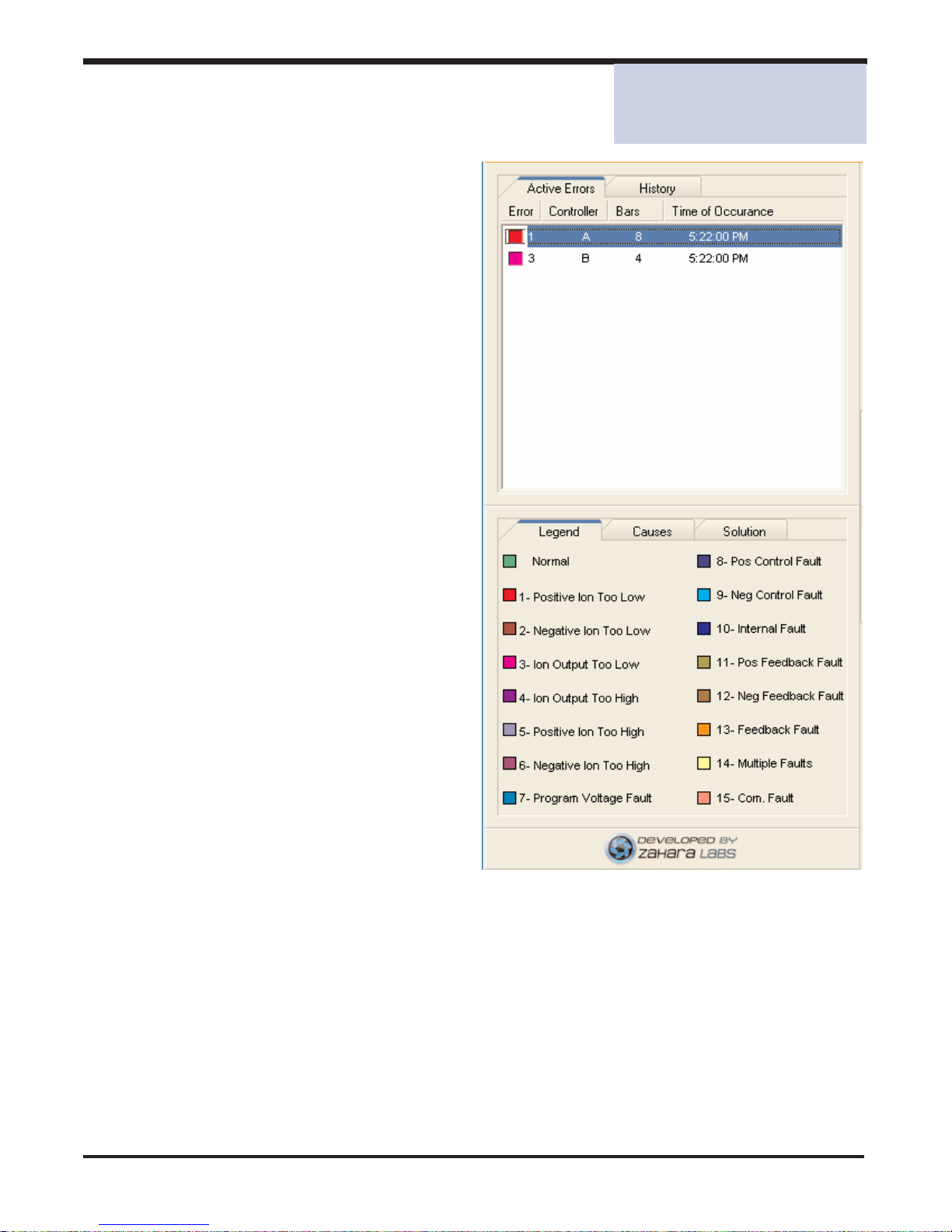
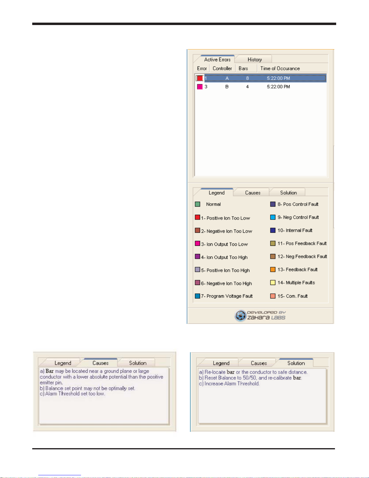
4.1 Active Errors
The top part of the Status Panel shows all
active error conditions. Each error is color
coded, identifies the Controller and the
Emitter experiencing the error, and the time
the error occurred.
4.2 History
A History tab next to the Active Tab lists all
corrected errors that have transpired.
4.3 Legend
In the lower part of the panel there is a
Legend that identifies error codes by ID
and by color.
14
SECTION 4 - Status Panel
SECTION 4
Status Panel
Page 16
Simco Ionization for Electronics Manufacture Publication 5200943
4.5 Solution Tab
The Solution Tab displays possible
Solutions/corrective measures that can be
taken to eliminate an Error. The information
displayed is updated based on the error
selected in the Active Error list.
15
4.4 Causes Tab
The Causes Tab displays possible Causes of
an Error. The information displayed is updated based on the error selected in the Active
Error list.
SECTION 4 - Status Panel
Page 17
Simco Ionization for Electronics Manufacture Publication 5200943
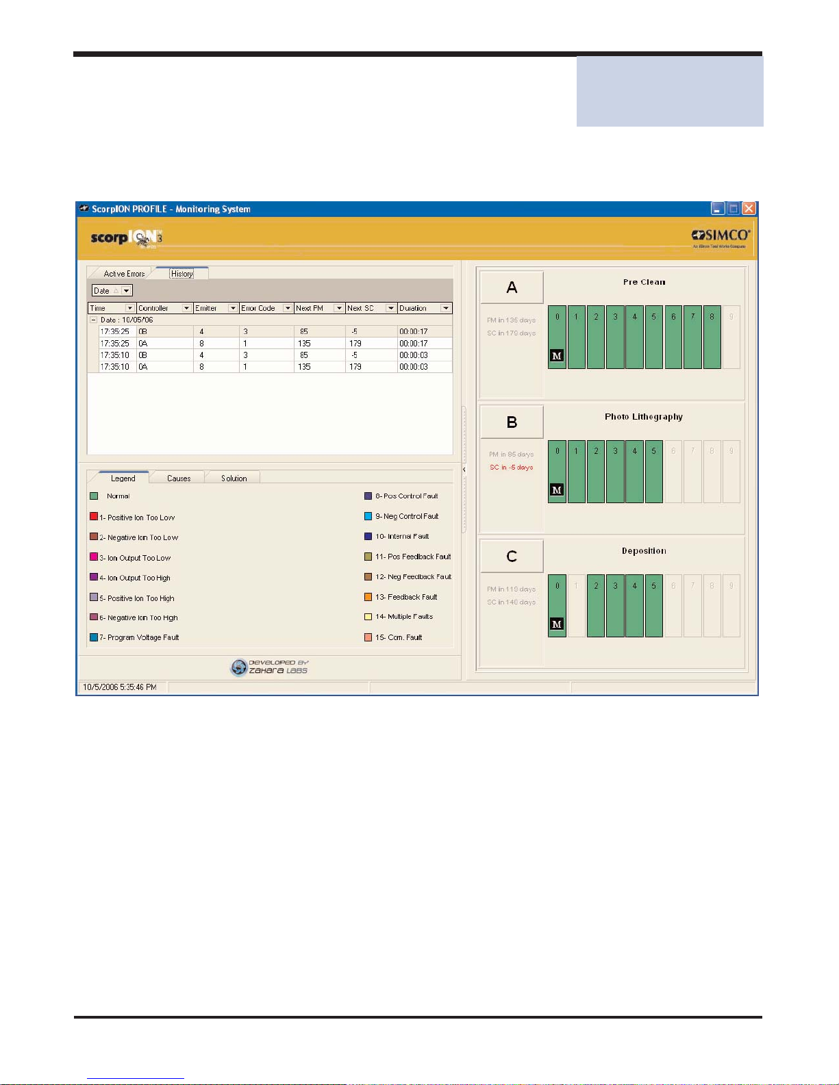
History Tab
The History tab displays a detailed history of corrected errors including the time of occurrence,
where they occurred (Controller / emitter), what type of error occurred and the duration of the error.
By including information regarding the next preventative maintenance and next system calibration
we can gauge the need for servicing the system. Notice that controller B's System Calibration indicator is red. This happens because controller B should have had a System Calibration 5 days ago.
16
SECTION 5 - History Tab
SECTION 5
History Tab
Page 18

Simco Ionization for Electronics Manufacture Publication 5200943
17
Page 19
Simco Ionization for Electronics Manufacture Publication 5200943
Graphic Panel
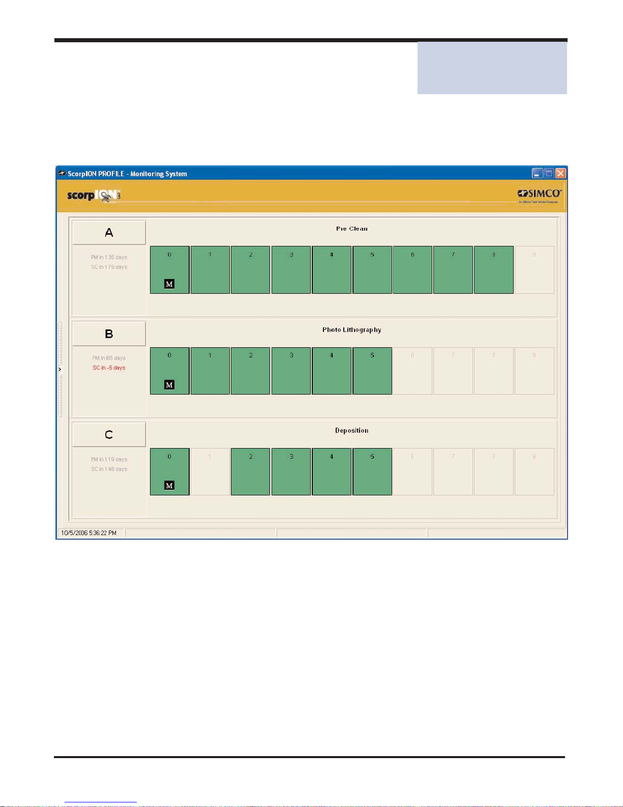
6.1 Full Screen Graphic View
By maximizing the Horizontal Divider or by dragging the divider to the left you can get a full screen
This view takes full advantage of the graphical capabilities of the application.
18
SECTION 6 - Graphic Panel
SECTION 6
Graphic Panel
Page 20

Simco Ionization for Electronics Manufacture Publication 5200943
19
Page 21
Simco Ionization for Electronics Manufacture Publication 5200943
Error Logging
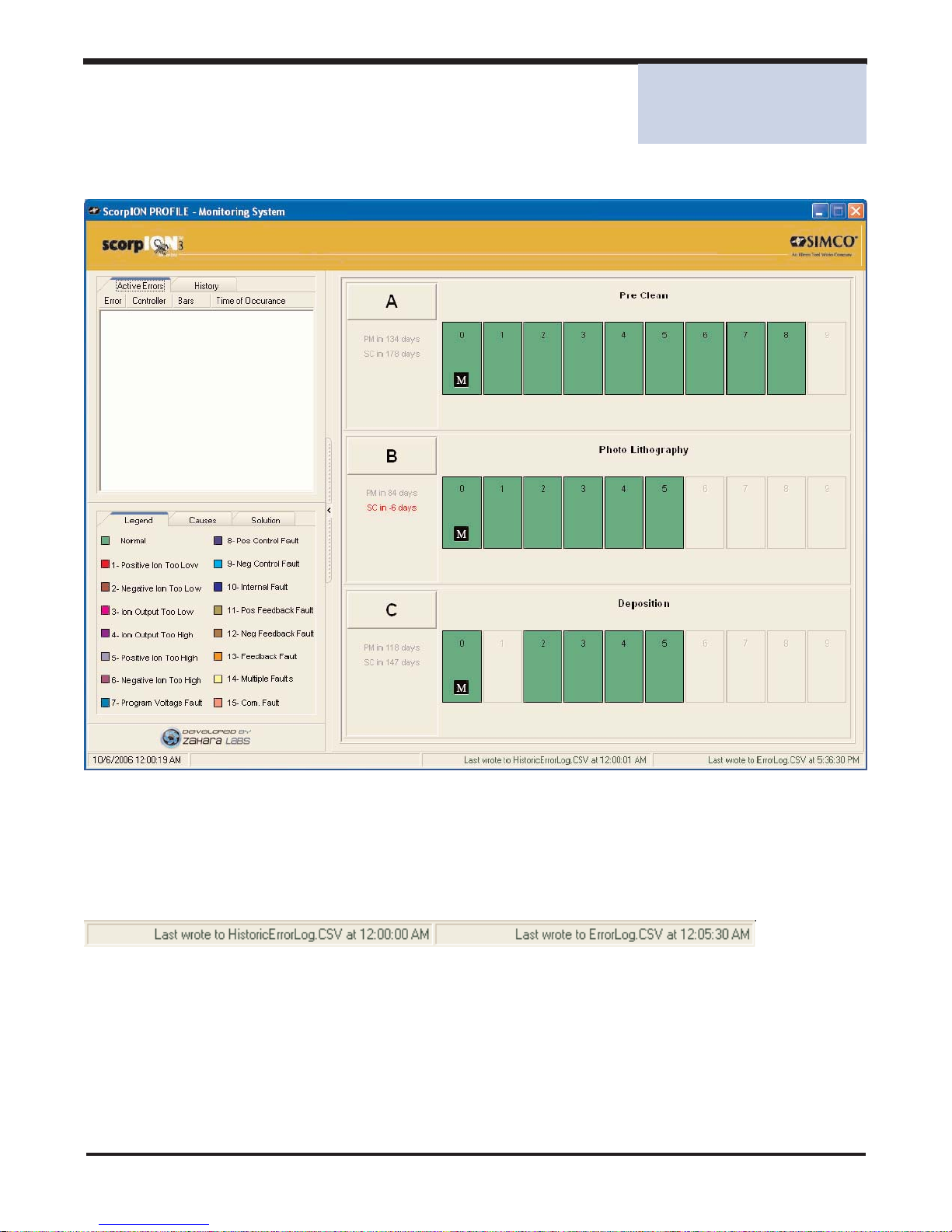
The status bar at the bottom of the screen informs the user of the error logging status.
20
7.1 Daily Error Logging
At midnight all errors are added to the HistoricErrorLog.csv file.
7.2 Active Error Logging
Active errors are monitored in memory in real time. A change in the state of the system; new error
or error cleared notifies the system that it should update the active error file ErrorLog.csv. The
active error file is updated at a maximum frequency of once a minute.
SECTION 7 - Error Logging
SECTION 7
Error Logging
Page 22
Simco Ionization for Electronics Manufacture Publication 5200943
7.3 An example with Error Conditions
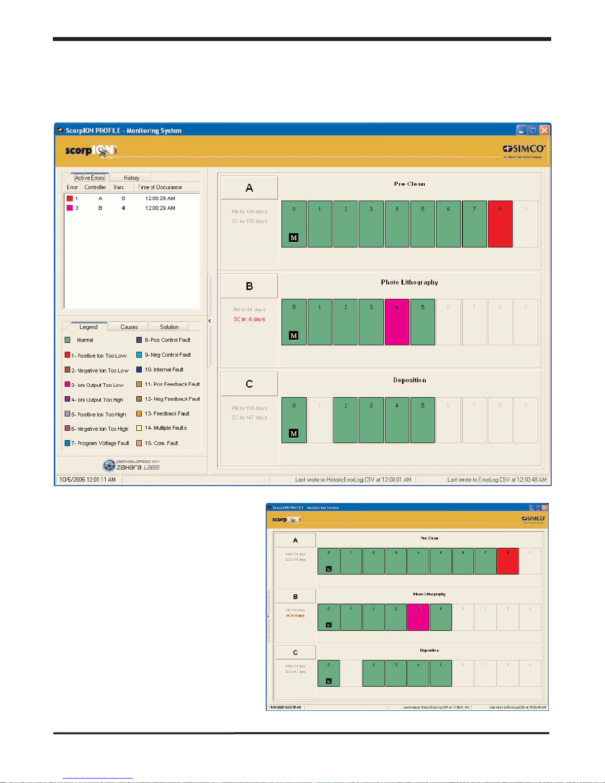
The following image illustrates Controller A having an active error condition and Controller B having
an active error condition. Each error occurred at 12:00:29 APM.
A full screen graphic view
of the above scenario is
illustrated to the right.
21
SECTION 7 - Error Logging
Page 23
Simco Ionization for Electronics Manufacture Publication 5200943
7.4 Context Sensitive Error Analysis
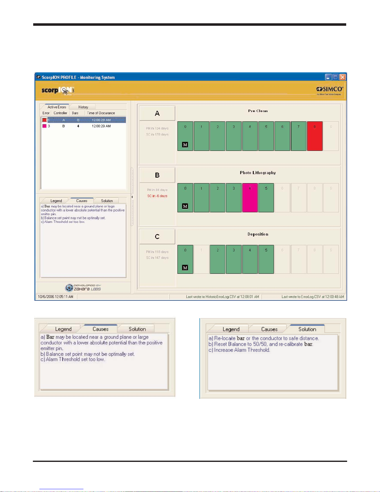
Selecting an active error triggers the Causes and Solution panels to dynamically update their
content providing appropriate Case/Solution information.
22
SECTION 7 - Error Logging
Page 24
Simco Ionization for Electronics Manufacture Publication 5200943
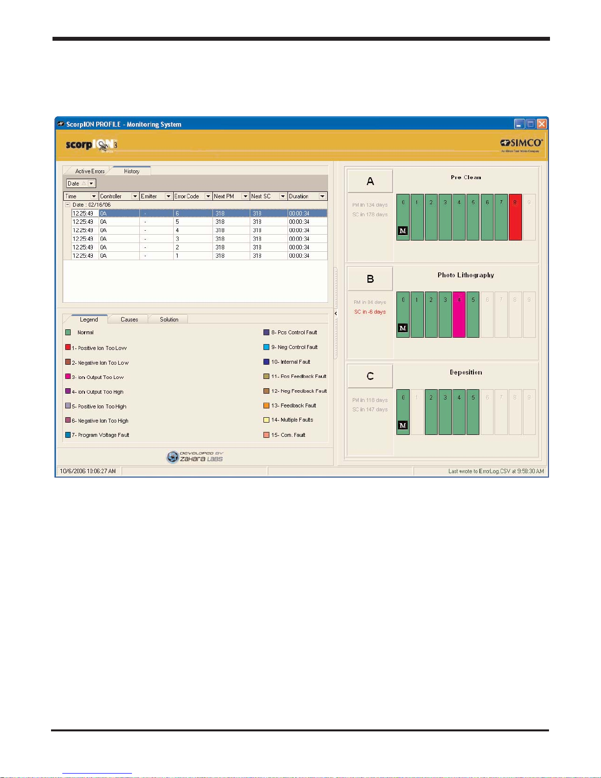
7.5 Expanded Historic View
By dragging the horizontal scroll bar to the right we expand the view of the History tab while also
maintaining an active graphical view.
23
SECTION 7 - Error Logging
Page 25
Simco Ionization for Electronics Manufacture Publication 5200943
24
Bar Modification
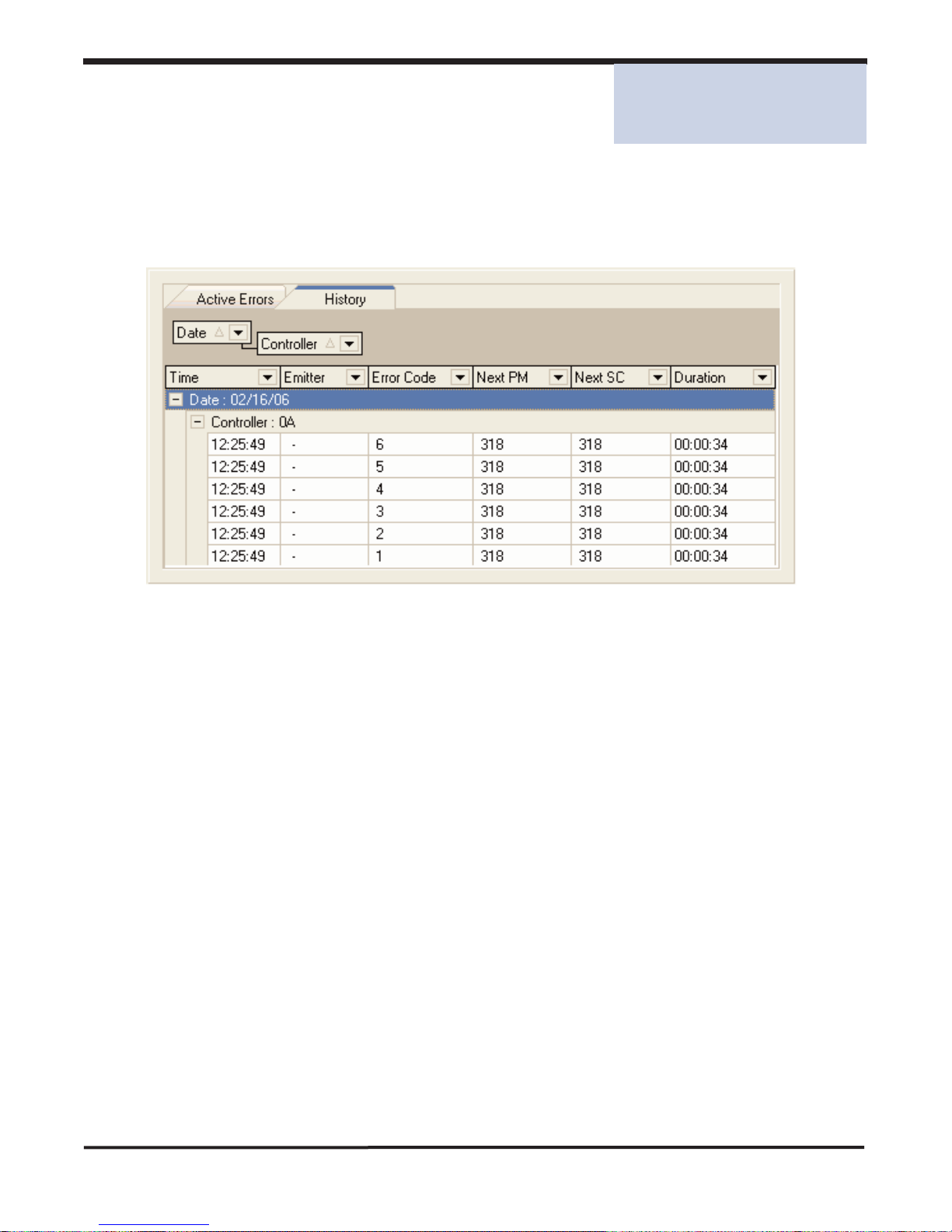
8.1 Custom Grouping History
By dragging a column header you may create dynamic groupings. In the example illustrated below
History events are grouped by Date and Controller.
SECTION 8 - Bar Modification
SECTION 8
Bar Modification
Page 26
Simco Ionization for Electronics Manufacture Publication 5200943
25
8.2 Modifying a Controller
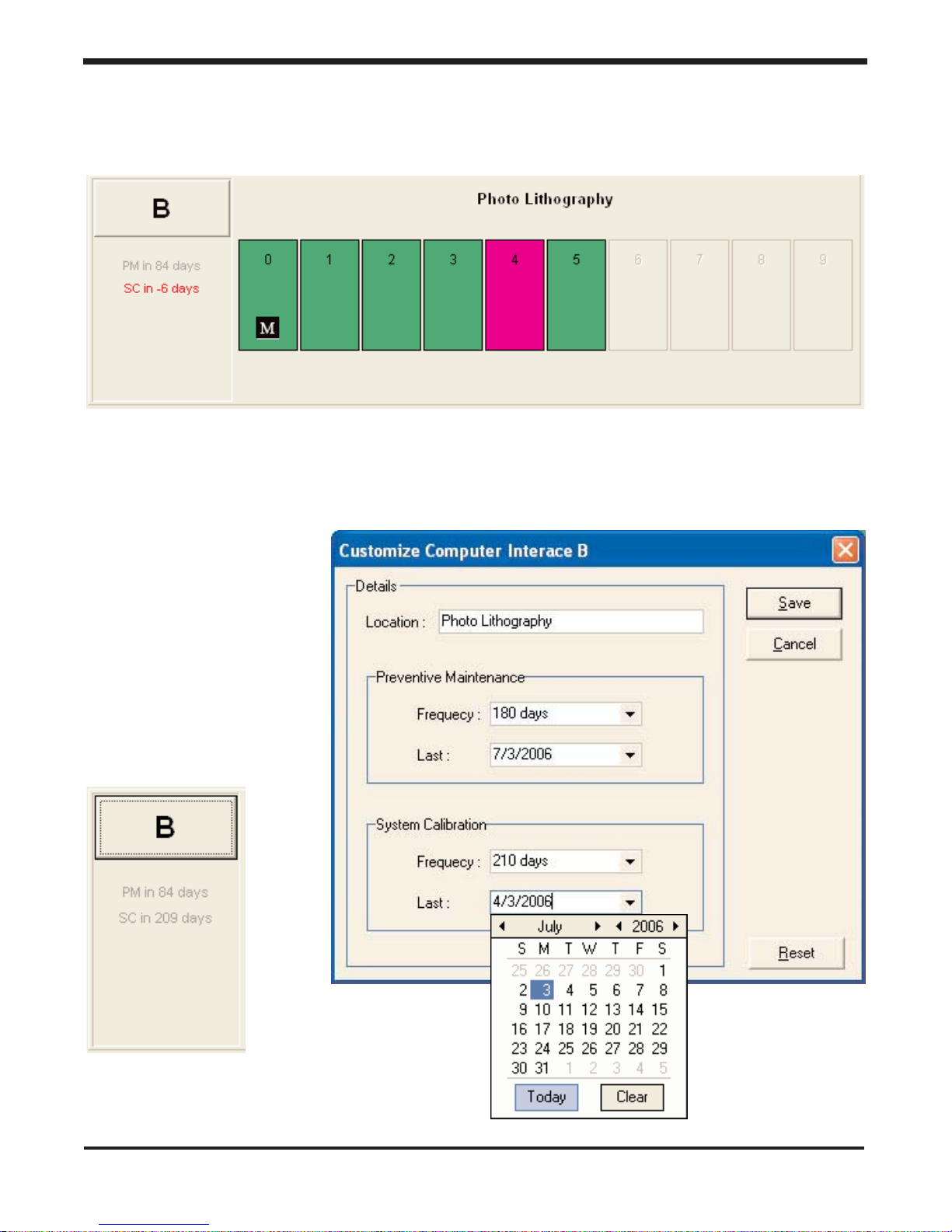
If you are logged in as a Manager you may modify a controller's information by clicking on the controller's ID button (labeled 'B' here).
You may modify the location, Preventative Maintenance or System Calibration values of a controller.
If for example, you have just performed a System Calibration use the drop down calendar to
update the Last performed field to today's date.
SECTION 8 - Bar Modification
Page 27
Simco Ionization for Electronics Manufacture Publication 5200943
26
8.3 Programming a Bar
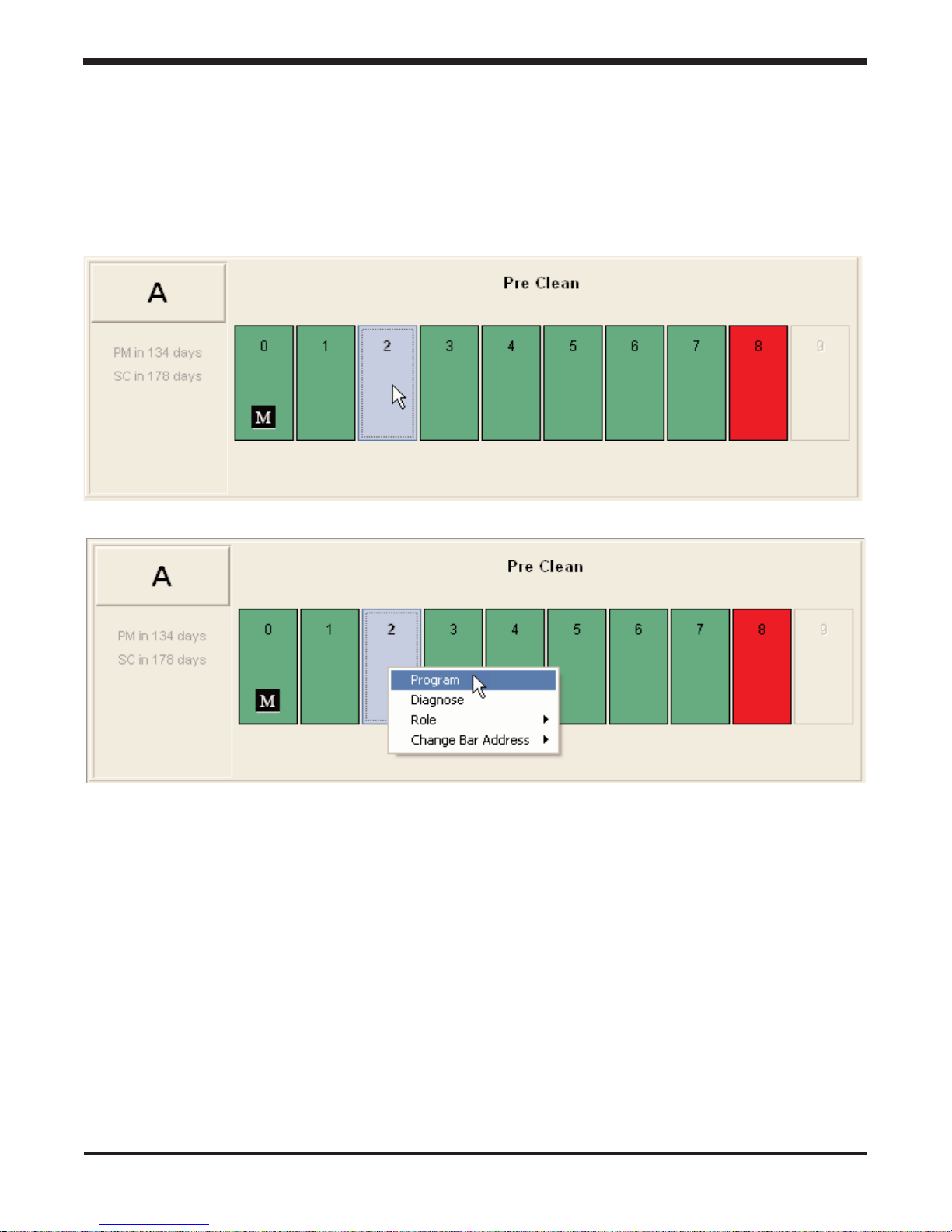
You may wish to make adjustments to a bar's settings. In order to perform this operation you could
right click on the bar of interest and select Program from the list of available operations.
Since programming a bar is the default operation for a bar, you could simply click on the bar to
select the Program operation.
SECTION 8 - Bar Modification
Page 28
Simco Ionization for Electronics Manufacture Publication 5200943
27
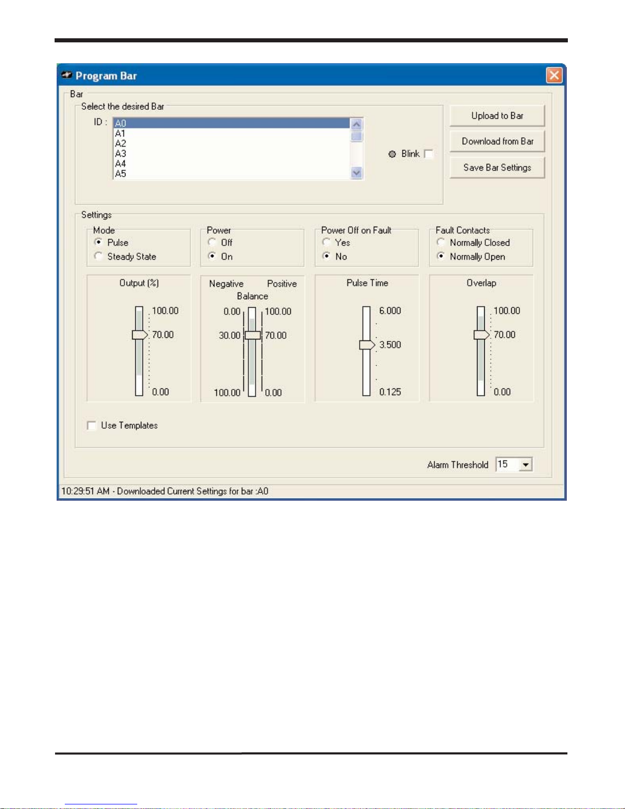
Click to highlight the bar you wish to program. Click Download from Bar to see the current settings. Make adjustments as desired and click Upload to Bar. When you are satisfied with the settings click Save Bar Settings. Close the application without saving to revert to the original settings.
Power Off on Fault causes the bar to stop producing ions any time a fault condition is encountered
by the bar.
Highlighting a bar address and then checking the Blink box causes the scorpION3 bar mounted
power indicators to blink rapidly. This is useful as a means to identify a particular bar address and
location.
SECTION 8 - Bar Modification
Page 29
Simco Ionization for Electronics Manufacture Publication 5200943
28
8.4 Diagnosing a Bar
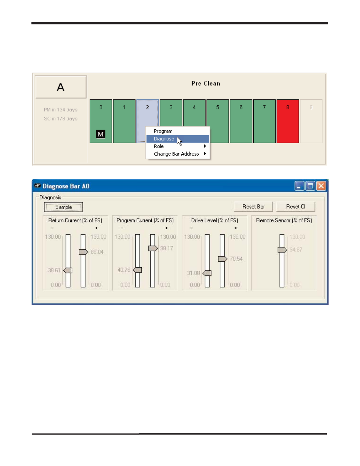
You may wish to Diagnose a bar. In order to perform this operation you would right click on the bar
of interest and select Diagnose from the list of available operations.
To diagnose the selected bar you must click Sample to retrieve the current bar performance level
and Program Current settings.
SECTION 8 - Bar Modification
Page 30
Simco Ionization for Electronics Manufacture Publication 5200943
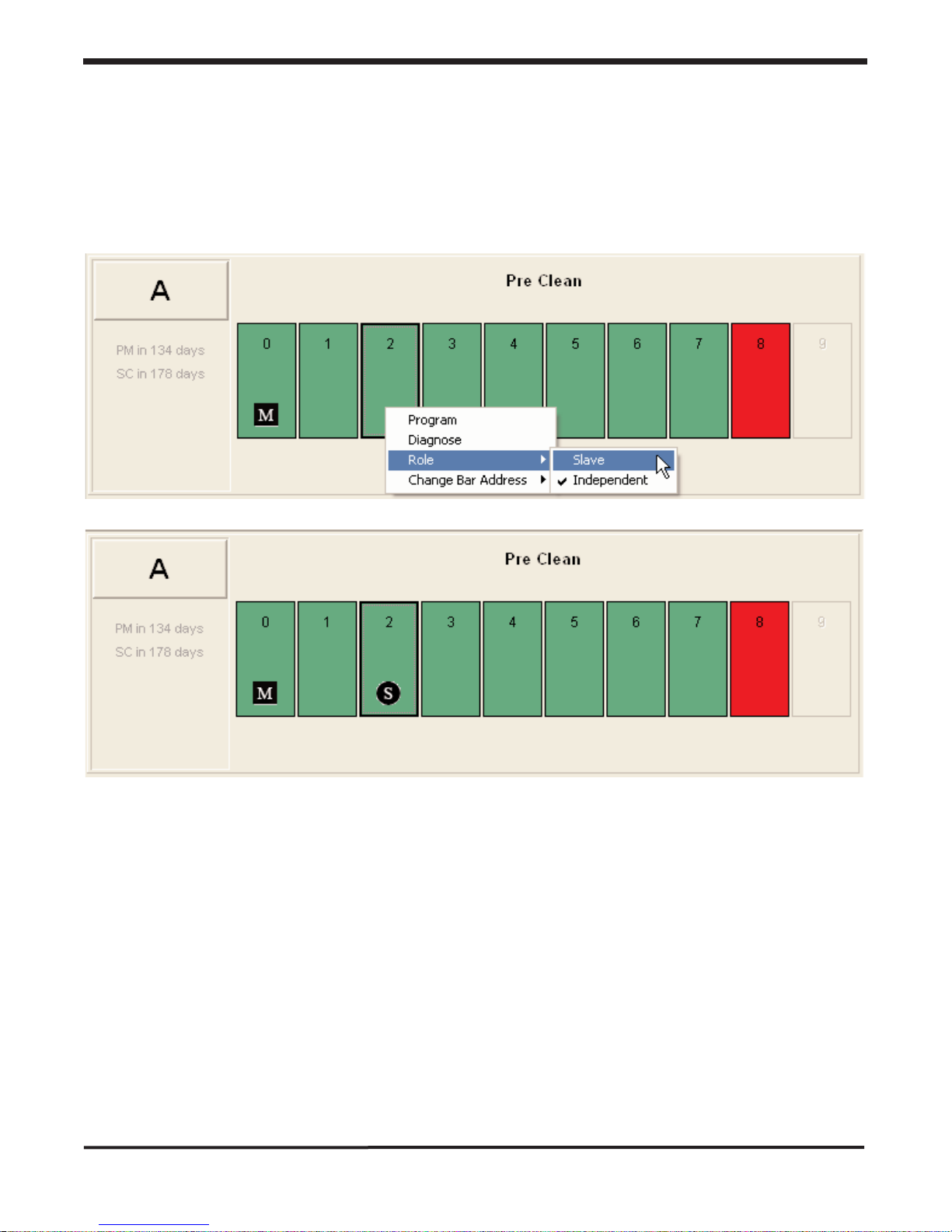
8.5 Changing the Role of a Bar
You may wish to make adjustments to a bar's Role. In order to perform this operation you could
right click on the bar of interest and select Role from the list of available operations.
The first bar (Bar 0) is always a Master. All other bars can be set to Independent or Slave. Master
and Slave Roles are illustrated with the "M" and "S" and Independent bars are unmarked.
29
SECTION 8 - Bar Modification
Page 31
Simco Ionization for Electronics Manufacture Publication 5200943
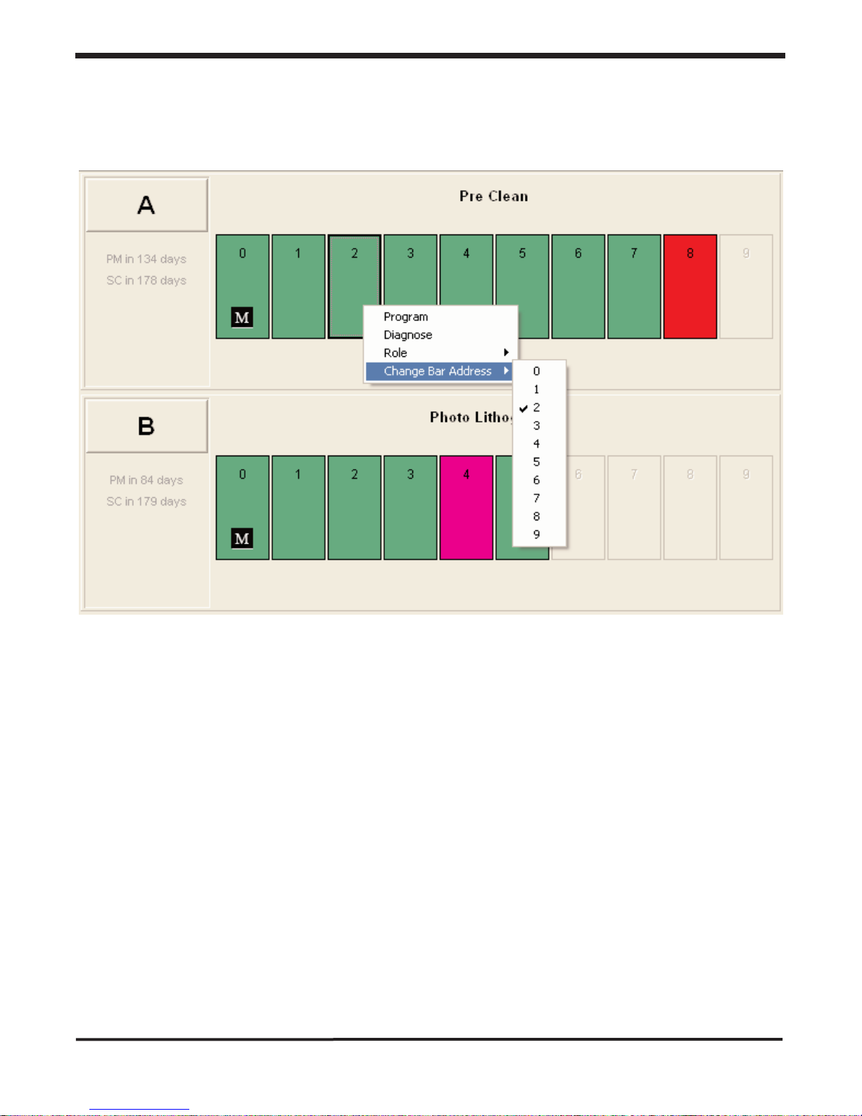
8.6 Changing the Address of Bar
You may wish to make adjustments to a bar's Address. In order to perform this operation you could
right click on the bar of interest and select Change Bar Address from the list of available operations.
30
SECTION 8 - Bar Modification
Page 32

Simco Ionization for Electronics Manufacture Publication 5200943
31
Page 33

Simco Ionization for Electronics Manufacture Publication 5200943
Notes:
32
Page 34
Simco Ionization for Electronics Manufacture Publication 5200943
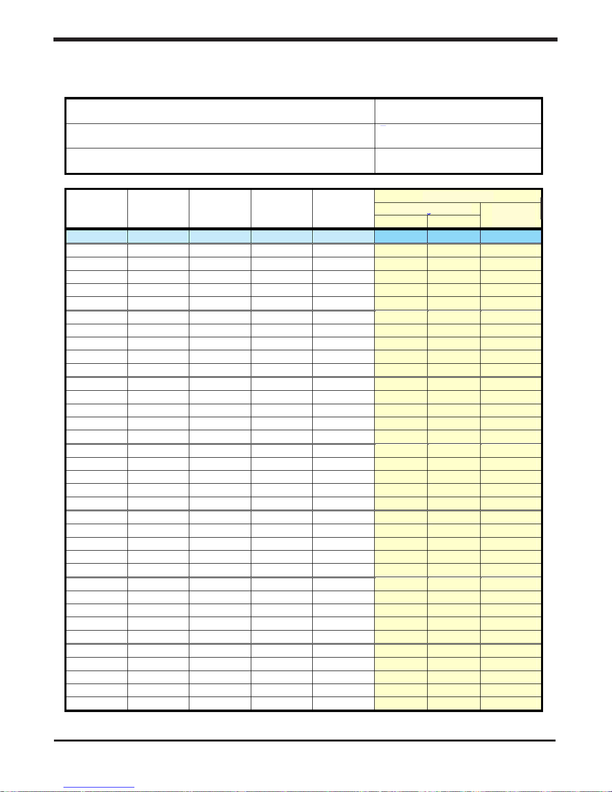
SSyysstteemm SSeettttiinnggss DDaattaa LLoogg
Controller ID:
Pulse Time System Setting:
Recorded By:
Emitter
Address
Balance
Setting
Ion Output
Setting
Mode
Setting
Power
Setting
Date:
Temperature:
Humidity:
Test Results
Discharge Time
Offset
Voltage
-2.0 volts
12.5 sec
8.4 sec
Example
50/50 1.00 Pulse On
33
Controller ID: Date:
Pulse Time System Setting: Temperature:
Recorded By: Humidity:
Emitter
Address
Example 50/50 1.00 Pulse On 8.4 sec 12.5 sec -2.0 volts
Balance
Setting
Ion Output
Setting
Mode
Setting
Power
Setting
Test Results
Discharge Time
+ -
Offset
Voltage
 Loading...