

Page 1
b
G
e
d
e
t
O
n
a
a
R
p
t
o
n
d
e
t
e
8
o
c
N
SIMCO (Ne
Postbus 71
NL-7240 AB
Telefoon +
Telefax +
E-mail g
Internet ht
Traderegist
erland) B.V.
Lochem
31-(0)573-2
31-(0)573-25
neral@simc
tp://www.sim
r Apeldoorn
8333
7319
-ion.nl
o-ion.nl
o. 08046136
Ionisati
Ionizing
C
pistool
Air Gu
B
A
Ionens
Pistole
rühpist
à Air Io
le
isé
NL Ge
D Be
GB Us
F No
Co
ra_UM_97520
50610_NL_D_
B_F_V2_1
bruikersh
ienungsa
r's Manu
ice d'utilis
ndleiding
nleitung
l
ation
1
8
15
22
Page 2

INHOUDSOPGAVE
1. Inleiding .................................................................................................................................... 2
2. Veiligheid ................................................................................................................................. 2
3. Toepassing en werking ............................................................................................................ 2
4. Technische specificaties .......................................................................................................... 3
5. Installatie .................................................................................................................................. 3
5.1. Controle ............................................................................................................................. 3
5.2. Installatie ........................................................................................................................... 3
5.2.1. Montage voedingsapparaat ........................................................................................ 3
5.2.2. Montage van pistool aan voedingsapparaat .............................................................. 4
5.2.3. Aansluiten perslucht. ................................................................................................... 4
6. Ingebruikneming ...................................................................................................................... 4
7. Controle op de werking ............................................................................................................ 5
8. Onderhoud ............................................................................................................................... 5
8.1. Pistool ................................................................................................................................ 5
8.2. Voedingsapparaat ............................................................................................................. 5
9. Storingen .................................................................................................................................. 5
9.1. Voedingsapparaat ............................................................................................................. 5
9.2. Cobra pistool ..................................................................................................................... 6
10. Reparatie ............................................................................................................................... 6
10.1. Cobra pistool ................................................................................................................... 6
10.2. Voedingsapparaat ........................................................................................................... 6
11. Afdanken ................................................................................................................................ 7
12. Reserveonderdelen ................................................................................................................ 7
12.1. Onderdelen Cobra pistool ................................................................................................ 7
12.2 Onderdelen Voedingsapparaat A..A5G ............................................................................ 7
Cobra_UM_9752050610_NL_D_GB_F_V2_1 1
NL
Page 3

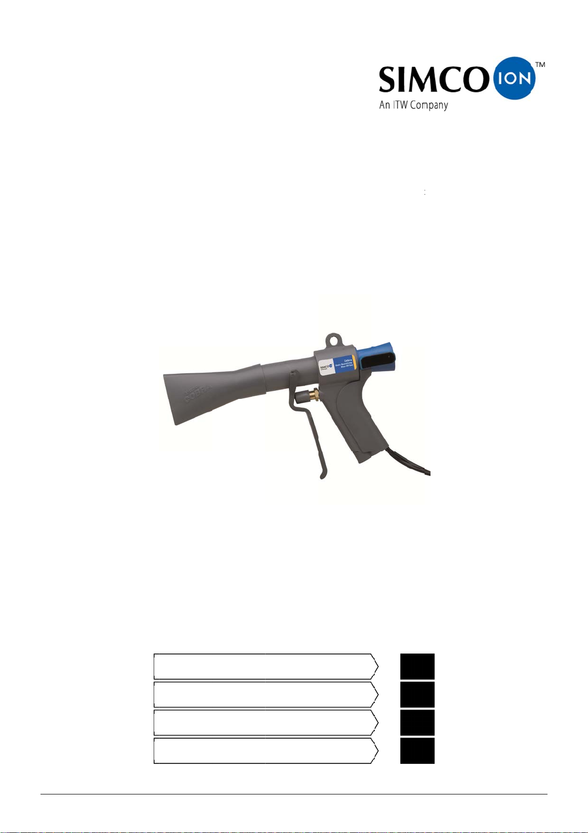
GEBRUIKERSHANDLEIDING COBRA IONISATIEPISTOOL
1. Inleiding
Lees deze handleiding geheel door voordat u dit product installeert en/of in gebruik neemt.
Instructies in deze handleiding dienen te worden opgevolgd om een goede werking van het product te waarborgen en om aanspraak te kunnen maken op garantie.
De garantiebepalingen zijn omschreven in de Algemene Verkoopvoorwaarden van SIMCO
(Nederland) B.V.
2. Veiligheid
Het Cobra ionisatie pistool is uitsluitend bestemd voor het schoonblazen en gelijktijdig
neutraliseren van elektrostatisch geladen oppervlakken.
Elektrische installatie en reparatie dienen te geschieden door een elektrotechnisch vakbe-
kwaam persoon.
Bij werkzaamheden aan de apparatuur: apparatuur spanningsloos maken
Zorg voor een goede aarding van het voedingsapparaat.
Aarding is nodig voor een goede werking en voorkomt, bij aanraking, elektrische schokken.
Bij regelmatig gebruik van het pistool is gehoorbescherming verplicht.
Indien zonder schriftelijke toestemming vooraf wijzigingen, aanpassingen etc. zijn aange-
bracht of bij reparatie niet originele onderdelen zijn gebruikt, verliest het apparaat CE goedkeuring en garantie.
3. Toepassing en werking
Het Cobra ionisatiepistool wordt toegepast daar waar men materialen wenst schoon te blazen
en gelijktijdig te neutraliseren. Door de grote hoeveelheid uitgeblazen lucht is het pistool geschikt voor het schoonblazen van grotere oppervlakken.
Het Cobra ionisatiepistool is een perslucht pistool met een ionisatiepunt in de luchtdoorgang.
Het pistool dient te worden aangesloten op een Simco-Ion voedingsapparaat. Dit voedingsapparaat levert de hoogspanning voor de ionisatiepunt.
De Cobra produceert een luchtstroom die rijk is aan positieve en negatieve ionen. Door deze
luchtstroom te richten op een elektrostatisch geladen oppervlak vindt er een uitwisseling van
elektronen plaats waardoor tijdens het schoonblazen het oppervlak wordt geneutraliseerd. Hierdoor voorkomt u het opnieuw aantrekken van de afgeblazen deeltjes.
Door de venturie werking van het pistool is de hoeveelheid uitgeblazen lucht ca 5,5 keer groter
dan de gebruikte hoeveelheid perslucht.
Door toepassing van het mondstuk wordt een brede luchtstroom gevormd en kan in één beweging een groot oppervlak worden gereinigd.
Cobra_UM_9752050610_NL_D_GB_F_V2_1 2
Page 4
4. Technische specificaties
Werkspanning: ca 5,1 kV ac
max. stroom aan punt: 0,25 mA
Voedingsapparaat: A2A5G voor 230 V art. nr.: 08.05.25.5700
Drukmedium: lucht of stikstof
luchtaansluiting: ¼ “ BSP, slang min. 9 mm inwendig
luchtverbruik: 400 l/min bij 3,5 Bar
625 l/min bij 7 Bar
Luchtverplaatsing: 2250 l/min bij 3,5 Bar
3700 l/min bij 7 Bar
Geluidsniveau: 92 dB bij 2 bar
(gemeten op 30 cm 96 dB bij 4 bar
afstand van het pistool) 101 dB bij 7 bar
5. Installatie
5.1. Controle
Controleer of het Cobra pistool, en het eventueel meegeleverde voedingsapparaat,
onbeschadigd en in de juiste uitvoering ontvangen zijn.
Controleer of de pakbongegevens overeenkomen met de gegevens van het ontvangen
product.
Controleer of de spanning, aangegeven op het typeplaatje van het voedingsapparaat,
overeenkomt met de aansluitspanning.
Bij problemen en/of onduidelijkheden:
Neem contact op met Simco-Ion of met de agent in uw regio
5.2. Installatie
5.2.1. Montage voedingsapparaat
Waarschuwing:
Elektrische installatie dient te geschieden door een elektrotechnisch vakbekwaam
persoon.
Bij werkzaamheden aan de apparatuur: apparatuur spanningsloos maken.
- Plaats / monteer het voedingsapparaat op de door u gewenste plaats, op een zodanige
wijze dat de schakelaar en het neonlampje goed bereikbaar en zichtbaar zijn.
- Bevestig het voedingsapparaat middels de bevestigingsgaten in de bodemplaat.
- Verleg het aansluitsnoer naar het aansluitpunt van de (net)spanning.
- Sluit het aansluitsnoer aan of monteer een stekker.
Belangrijk:
Zorg voor een goede aarding van de apparatuur. Aarding is nodig voor een goede
werking en voorkomt bij aanraking elektrische schokken.
Cobra_UM_9752050610_NL_D_GB_F_V2_1 3
NL
Page 5
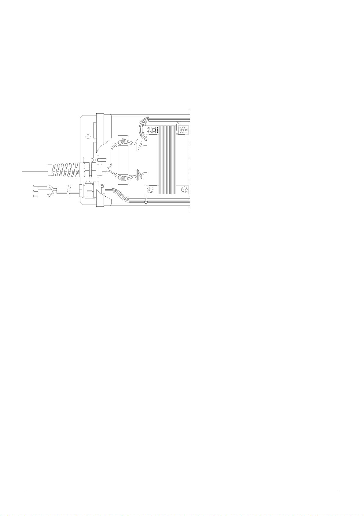
5.2.2. Montage van pistool aan voedingsapparaat
1. Verwijder het deksel van het voedingsapparaat.
2. Verwijder een van de middelste blindwartels uit de achterzijde van kast.
3. Monteer hierin de wartel met de pistoolkabel.
4. Bevestig de draden van het pistool elk onder een aansluitschroef.
5. Trekontlasting van wartel vastdraaien.
6. Plaats het deksel weer op de kast en schroef deze vast.
aansluiting Cobra
Belangrijk:
HS kabel niet met een lus in de kast verleggen
5.2.3. Aansluiten perslucht.
Belangrijk:
De te gebruiken perslucht moet schoon, droog en vrij van olie te zijn.
Het gebruik van een luchtfilter wordt aanbevolen.
Gebruik een drukregelaar om de afblaaskracht in te stellen.
1. Verwijder de lucht aansluitnippel uit het pistool.
2. Wikkel afdicht tape om de nippel.
3. Draai de nippel in het pistool.
4. Monteer de luchtslang aan de aansluitnippel.
5. Sluit de luchtslang aan op uw perslucht installatie.
6. Ingebruikneming
Zorg dat er perslucht op het pistool staat.
Schakel het voedingsapparaat in.
Richt het pistool op het schoon te blazen object.
Trekker van pistool overhalen.
Cobra_UM_9752050610_NL_D_GB_F_V2_1 4
Page 6
7. Controle op de werking
Het indicatielampje op het voedingsapparaat geeft een indicatie voor de aanwezige
hoogspanning.
Met en Simco-Ion staaftester kan worden gecontroleerd of de hoogspanning op de ionisatiepunt
van het pistool aanwezig is.
Voor het bepalen van de efficiency van het ionisatiepistool dient een veldsterktemeter te worden
gebruikt.
Meet de lading op het materiaal voor en na het schoonblazen met het pistool.
De gemeten lading dient na het schoonblazen verdwenen te zijn.
8. Onderhoud
8.1. Pistool
Houdt het pistool schoon en droog
HS kabel periodiek controleren op beschadigingen
Ventielasje af en toe van een druppeltje olie voorzien
Het pistool valt onder de Europese richtlijn Arbeidsmiddelen (89/655EEG en 95/63EEG) en
dient overeenkomstig deze norm periodiek te worden gecontroleerd.
8.2. Voedingsapparaat
Houdt het voedingsapparaat schoon en droog.
Het bevat geen onderdelen welke onderhoud behoeven.
9. Storingen
9.1. Voedingsapparaat
Probleem Oorzaak Oplossing
Signaallampjes schakelaar
en HS indicatie branden
niet.
Voedingsapparaat staat uit Voedingsapparaat inscha-
Schakelaar defect Schakelaar vervangen
Neon lampje HS indicatie
brand niet. Lampje
schakelaar brand wel. Trafo defect Trafo vervangen
Neonlampje defect Neonlampje vervangen
tabel 1 storingen
Geen aansluitspanning Aansluitspanning inschake-
len
kelen
Kortsluiting in aangesloten
apparatuur.
Kortsluiting opsporen en
verhelpen.
NL
Cobra_UM_9752050610_NL_D_GB_F_V2_1 5
Page 7
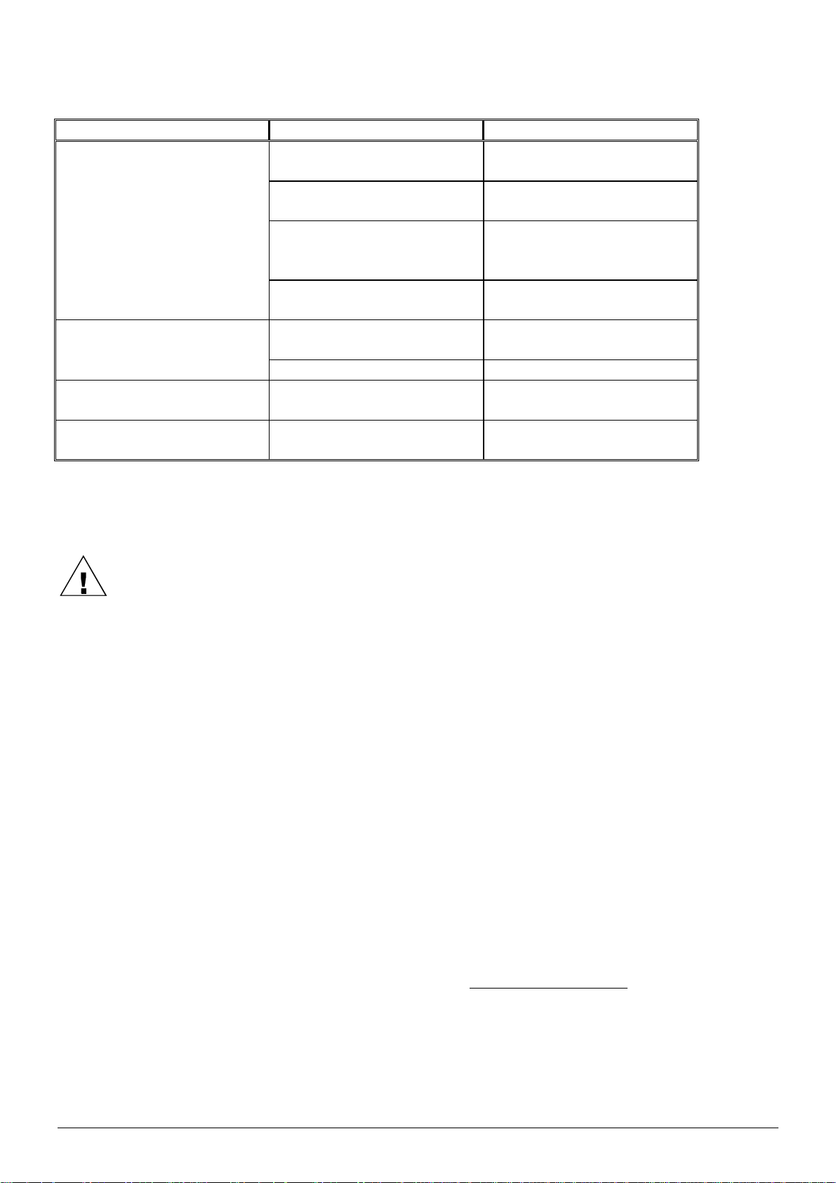
9.2. Cobra pistool
Probleem Oorzaak Oplossing
Pistool ioniseert niet of onvoldoende
Voedingsapparaat niet ingeschakeld
Voedingsapparaat inschakelen
Voedingsapparaat defect Zie handleiding voedings-
apparaat
HS kabel onderbroken HS kabel indien mogelijk
inkorten of pistool ter reparatie opsturen
Ionisatiedeel defect Pistool ter reparatie
opsturen
Geen perslucht uit het pi-
Perslucht niet aangesloten Perslucht aansluiten
stool
Ventiel defect Ventiel vervangen
Onvoldoende perslucht Druk perslucht te laag
ingesteld
Ventiel blijft hangen Ventiel ondervind bij in-
Druk perslucht juist instellen
Ventiel as smeren
drukken te veel weerstand
tabel 2 storingen
10. Reparatie
Waarschuwing:
Bij werkzaamheden aan de apparatuur: apparatuur spanningsloos maken
Reparatie dient te geschieden door een vakbekwaam persoon
10.1. Cobra pistool
Een beschadigde HS kabel kan eventueel worden ingekort.
1. Knip de kabel bij de beschadiging af
2. Mantel HS kabel 40 mm afstrippen
3. Aders 6 mm afstrippen
4. Aders voorzien van oogkabelschoen M3
Voor bestelling van onderdelen zie lijst reserveonderdelen.
10.2. Voedingsapparaat
Onderdelen van het voedingsapparaat kunnen niet worden gerepareerd. Voor bestelling van
onderdelen zie lijst reserveonderdelen.
Wanneer onderdelen naar SIMCO (Nederland) B.V. worden gezonden:
- Vraag hiervoor per e-mail een RMA-formulier aan via service@simco-ion.nl.
- Verpak deze deugdelijk en vermeld duidelijk de reden van retour.
Cobra_UM_9752050610_NL_D_GB_F_V2_1 6
Page 8
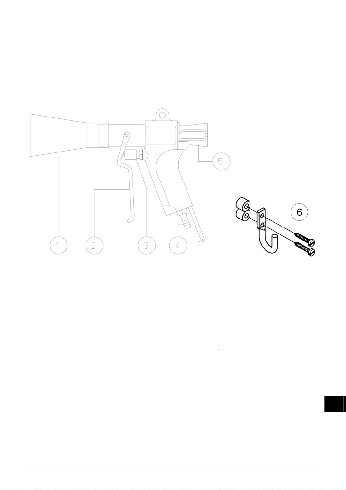
b
1
o
2
2
r
2
Ar
39393
8
3
k
e
v
d
A
e
d
0
1
0
2
0
G
n
d
b
m
c
e
e
Aa
a
p
l
s
e
e
a
a
a
n
g
m
j
v
p
o
o
A
e
t
e
0
0
a
k
s
1
. Afdan
V
lg voor h
1
. Reser
1
.1 Onder
en
t afdanke
eonder
elen Co
van het
elen
ra pistoo
roduct de
lokaal gel
dende (mi
lieu)regel
.
N
.
1
2
3
4
5
5
6
1
.2 Onder
tikel nr.
9
.60.25.21
.50.20.01
.90.60.10
3
.99.00.00
9
.30.93.22
rtik
65.06
65.06
65.00
92.90
65.06
65.06
65.06
lnummer
.50.3000
.90.1050
.50.3500
.00.1051
.50.1000
.50.1010
.50.0160
elen Voe
O
8 S
0 N
0 B
0
7 Tr
dingsapp
schrijvin
hakelaar
onlampje
schermka
nsluitblok
fo 230 V
Mond
Trekk
Venti
Lucht
Ionis
Ionis
Opha
Omschrij
tuk
l
ansluitni
tiedeel C
tiedeel C
gbeugel
raat A..
et lampj
HS Indica
pje schak
e HV
50 Hz 5,1
ing
pel 8 x ¼
bra met 2
bra met 4
5G
ie
laar/neon
kV
“ NPT
' (6 m) k
' (12 m)
lamp
bel
abel
NL
Co
ra_UM_97520
50610_NL_D_
B_F_V2_1
7
Page 9

INHALT
1. Einführung ................................................................................................................................ 9
2. Sicherheit ................................................................................................................................. 9
3. Einsatz und Funktionsweise ..................................................................................................... 9
4. Technische Daten .................................................................................................................. 10
5. Installation .............................................................................................................................. 10
5.1 Kontrolle ........................................................................................................................... 10
5.2. Installation ....................................................................................................................... 10
5.2.1. Montage des Netzteils .............................................................................................. 10
5.2.2. Montage der Pistole am Netzteil ............................................................................... 11
5.2.3. Druckluftschlauch anschließen ................................................................................. 11
6. Inbetriebnahme ...................................................................................................................... 11
7. Funktionsprüfung ................................................................................................................... 12
8. Wartung ................................................................................................................................. 12
8.1. Pistole .............................................................................................................................. 12
8.2. Netzteil ............................................................................................................................ 12
9. Störungen .............................................................................................................................. 12
9.1. Netzteil ............................................................................................................................ 12
9.2. Cobra Pistole ................................................................................................................... 13
10. Reparatur ............................................................................................................................. 13
10.1. Cobra Pistole ................................................................................................................. 13
10.2. Netzteil .......................................................................................................................... 13
11. Entsorgung ........................................................................................................................... 14
12. Ersatzteile ............................................................................................................................ 14
12.1. Ersatzteile Cobra Pistole ............................................................................................... 14
12.2. Ersatzteile Netzteil ......................................................................................................... 14
Cobra_UM_9752050610_NL_D_GB_F_V2_1 8
Page 10

BEDIENUNGSANLEITUNG FÜR DIE COBRA-IONENSPRÜHPISTOLE
1. Einführung
Lesen Sie diese Anleitung vor der Installation und/oder Inbetriebnahme dieses Produktes vollständig durch.
Befolgen Sie die Anweisungen in dieser Anleitung, um eine richtige Funktionsweise des Produktes sicherzustellen und irgendwelche Garantieansprüche geltend machen zu können.
Die Garantiebedingungen sind in den Allgemeinen Verkaufsbedingungen von SIMCO
(Nederland) B.V. festgelegt.
2. Sicherheit
Die Cobra-Ionensprühpistole wurde lediglich zum Sauberblasen und zur gleichzeitigen Neut-
ralisierung elektrostatisch geladener Flächen entwickelt.
Elektrische Anschluß- und Reparaturarbeiten sind von elektrotechnisch fachkundigem Per-
sonal durchzuführen.
Bei der Durchführung von Arbeiten am Gerät: das Gerät spannungslos machen.
Sorgen Sie für eine richtige Erdung des Netzteils.
Erdung ist für eine einwandfreie Funktionsweise erforderlich und verhindert Stromschläge bei
Berührung.
Bei regelmäßigem Gebrauch der Pistole ist die Anwendung von Gehörschutzmitteln zwin-
gend vorgeschrieben.
Wenn ohne vorhergehende schriftliche Genehmigung Änderungen, Anpassungen usw. vor-
genommen wurden, oder wenn bei Reparaturarbeiten andere als Originalteile verwendet
wurden, verliert das Gerät seine CE-Kennzeichnung und erlischt die Garantie.
3. Einsatz und Funktionsweise
Die Cobra-Ionensprühpistole wird zum Sauberblasen und zur gleichzeitigen Neutralisierung von
Teilen eingesetzt. Dank der großen Ausblaseluftmenge eignet sich die Pistole zum Sauberblasen größerer Flächen. Die Cobra-Ionensprühpistole ist eine Druckluftpistole mit einer Ionensprühspitze im Luftdurchgang. Die Pistole ist an ein Simco-Ion-Netzteil anzuschließen. Dieses
Netzteil liefert die für die Ionensprühspitze erforderliche Hochspannung. Die Cobra erzeugt einen Luftstrom mit viel positiven und negativen Ionen. Wenn dieser Luftstrom auf eine elektrostatisch geladene Fläche gerichtet wird, findet ein Elektronenaustausch statt, wodurch die Fläche
beim Sauberblasen neutralisiert wird. Hierdurch wird die Wiederanziehung der abgeblasenen
Teilchen verhindert.
Durch die Venturiwirkung der Pistole übersteigt die Ausblaseluftmenge die benutzte Druckluftmenge etwa um das 5,5 fache. Durch den Einsatz des Mundstücks wird ein breiter Luftstrom
erzeugt und kann in einer einzigen Bewegung eine große Fläche gereinigt werden.
Cobra_UM_9752050610_NL_D_GB_F_V2_1 9
D
Page 11
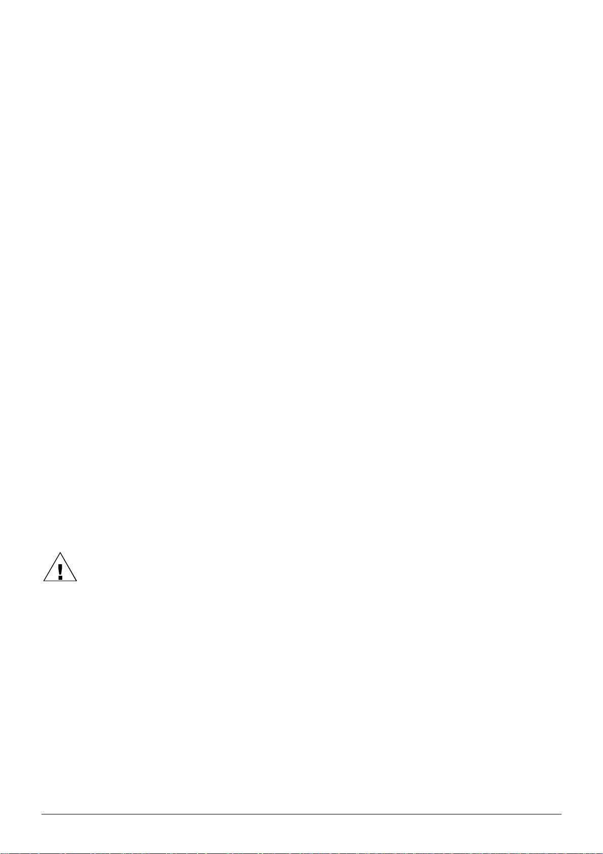
4. Technische Daten
Betriebsspannung: ca. 5,1 kV AC
Max. Stromstärke an der Spitze: 0,25 mA
Netzteil: A2A5G für 230 V Artikel-Nr. 08.05.25.5700
Druckmittel: Luft oder Stickstoff
Luftanschluß: ¼" BSP-Schlauch mit Innendurchmesser von
mindestens 9 mm
Luftverbrauch: 400 l/min bei 3,5 bar
625 l/min bei 7 bar
Luftleistung: 2250 l/min bei 3,5 bar
3700 l/min bei 7 bar
Schallpegel: 92 dB bei 2 bar
(in 30 cm Entfernung 96 dB bei 4 bar
von der Pistole gemessen) 101 dB bei 7 bar
5. Installation
5.1 Kontrolle
- Prüfen Sie, ob die Cobra-Pistole sowie das ggf. mitgelieferte Netzteil unbeschädigt sind und
ob Sie die richtige Ausführung erhalten haben.
- Prüfen Sie, ob die Angaben auf dem Packzettel mit den am Produkt angezeigten Daten
übereinstimmen.
- Prüfen Sie, ob die auf dem Typenschild angezeigte Spannung der Netzspannung entspricht.
Bei irgendwelchen Problemen und/oder Unklarheiten:
wenden Sie sich bitte an Simco-Ion oder Ihren Regionalagenten.
5.2. Installation
5.2.1. Montage des Netzteils
Warnung:
Elektrische Anschlußarbeiten sind von elektrotechnisch fachkundigem Personal
durchzuführen.
Bei der Durchführung von Arbeiten am Gerät: das Gerät spannungslos machen.
- Positionieren / montieren Sie das Netzteil dermaßen an der von Ihnen gewünschten Stelle,
daß der Schalter und die Neonlampe leicht zugänglich und gut sichtbar sind.
- Befestigen Sie das Netzteil mittels der Befestigungslöcher in der Bodenplatte.
- Verlegen Sie das Anschlußkabel zum Anschlußpunkt der (Netz)spannung.
- Schließen Sie das Anschlußkabel an oder montieren Sie einen Stecker.
Wichtig:
Sorgen Sie für eine richtige Geräte-Erdung. Erdung ist für eine einwandfreie Funkti-
onsweise erforderlich und verhindert Stromschläge bei Berührung.
Cobra_UM_9752050610_NL_D_GB_F_V2_1 10
Page 12
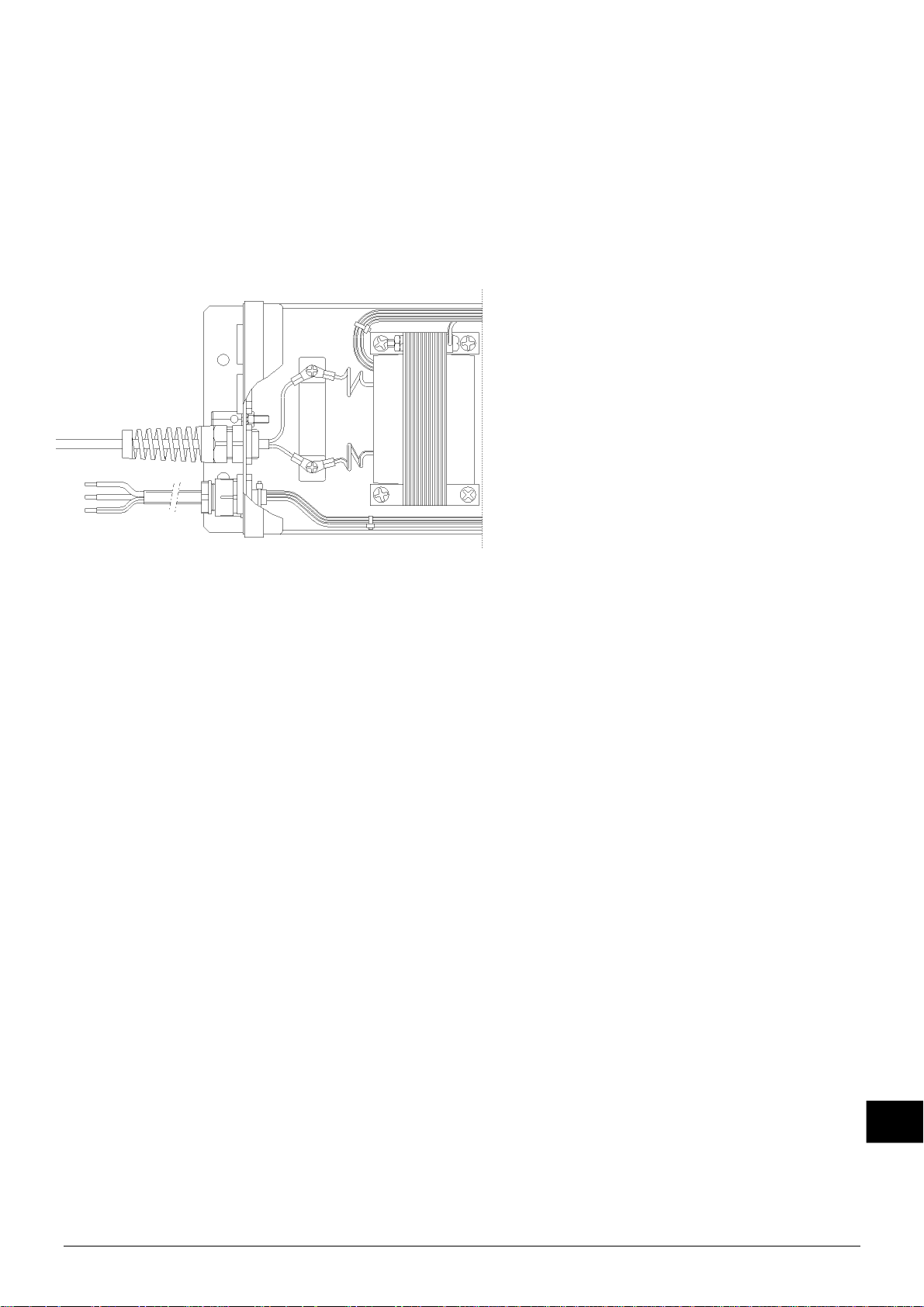
5.2.2. Montage der Pistole am Netzteil
1. Entfernen Sie den Deckel des Netzteils.
2. Entfernen Sie eine der mittleren Blindstopfbuchsen aus der Gehäuserückseite.
3. Bringen Sie an dieser Stelle die Stopfbuchse mit dem Pistolenkabel an.
4. Befestigen Sie die Verdrahtung der Pistole jeweils unter einer Anschlußschraube.
5. Ziehen Sie die Zugentlastung der Stopfbuchse fest.
6. Bringen Sie den Deckel wieder am Gehäuse an und ziehen Sie die vier Schrauben fest.
Anschluß der Cobra-Pistole
Wichtig:
HS-Kabel nicht mit einer Schlaufe im Gehäuse verlegen.
5.2.3. Druckluftschlauch anschließen
Wichtig:
Die zu verwendende Druckluft muß sauber, trocken und ölfrei sein.
Es empfiehlt sich, ein Luftfilter einzusetzen.
Verwenden Sie einen Druckregler zur Einstellung der Abblasekraft.
1. Nehmen Sie den Luftanschlußnippel aus der Pistole.
2. Wickeln Sie das Dichtungsklebeband um den Nippel herum.
3. Drehen Sie den Nippel in die Pistole.
4. Verbinden Sie den Luftschlauch mit dem Anschlußnippel.
5. Schließen Sie den Luftschlauch an Ihre Druckluftanlage an.
6. Inbetriebnahme
Sorgen Sie dafür, daß die Pistole mit Druckluft versorgt wird.
Schalten Sie das Netzteil ein.
Richten Sie die Pistole auf den sauberzublasenden Gegenstand.
Betätigen Sie den Abzug der Pistole.
D
Cobra_UM_9752050610_NL_D_GB_F_V2_1 11
Page 13
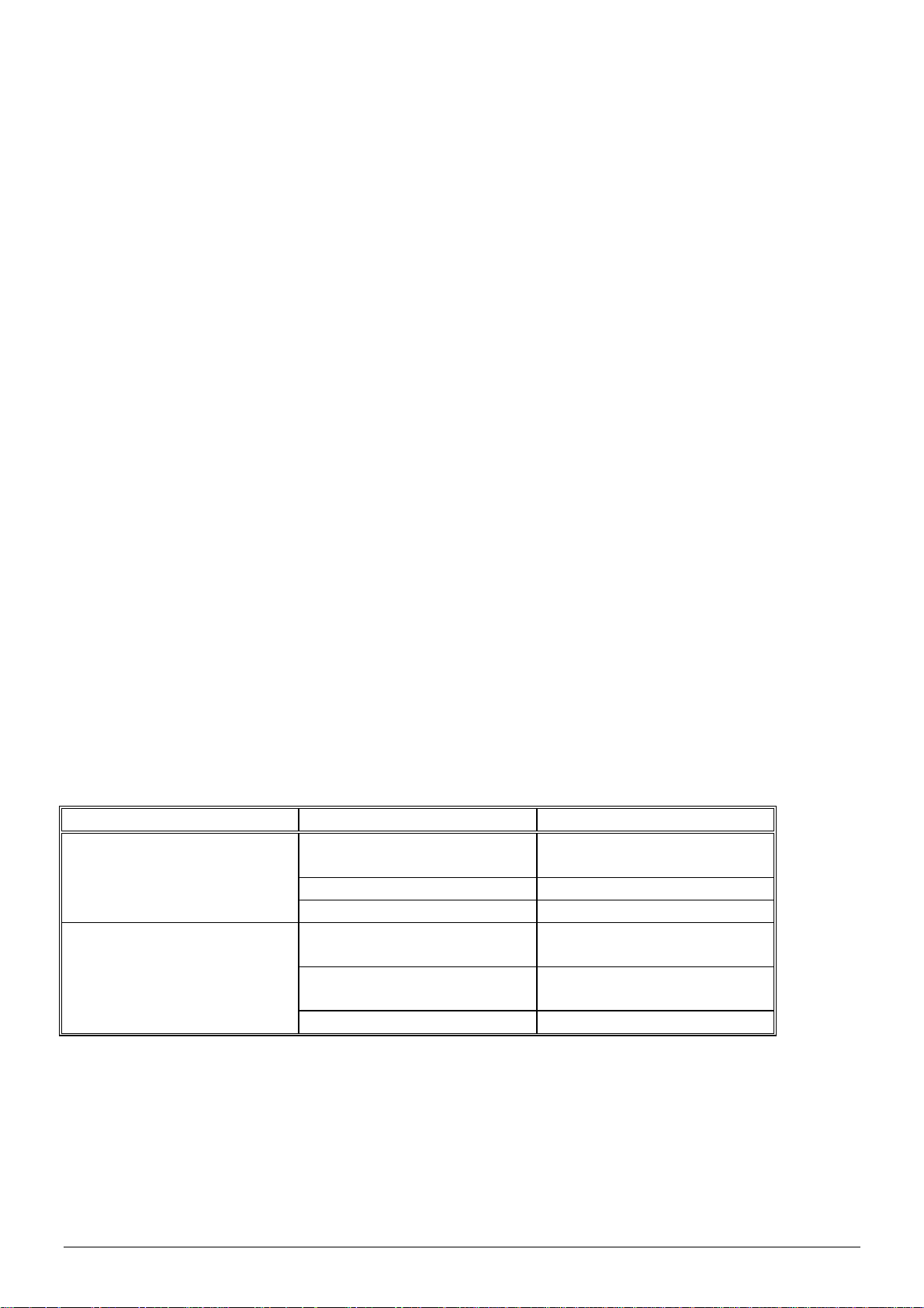
7. Funktionsprüfung
Die Anzeigelampe am Netzteil zeigt an, daß Hochspannung vorhanden ist.
Mit einem Ionensprühstabprüfer von Simco-Ion läßt sich feststellen, ob an der Ionensprühspitze
der Pistole Hochspannung anliegt.
Der Wirkungsgrad der Ionensprühpistole läßt sich mit einem Feldstärkemeßgerät ermitteln.
Messen Sie die statische Ladung am Material vor und nach dem Sauberblasen mit der Pistole.
Die gemessene Ladung sollte nach dem Sauberblasen verschwunden sein. Messen Sie die
statische Ladung am Material vor und nach dem Sauberblasen mit der Pistole.
8. Wartung
8.1. Pistole
- Halten Sie die Pistole sauber und trocken.
- Prüfen Sie die HS-Verkabelung regelmäßig auf Beschädigungen.
- Schmieren Sie die Ventilspindel hin und wieder mit einem Öltropfen ein.
Die Pistole fällt unter die europäische Arbeitsmittel-Richtlinie (89/655EWG und 95/63EWG) und
ist gemäß dieser Norm turnusmäßig zu überprüfen.
8.2. Netzteil
- Halten Sie das Netzteil sauber und trocken.
- Es enthält keine wartungsbedürftigen Einzelteile.
9. Störungen
9.1. Netzteil
Problem Ursache Abhilfe
Signalleuchtenschalter und
HS-Anzeige leuchten nicht
Netzteil ist ausgeschaltet Netzteil einschalten
Schalter defekt Schalter auswechseln
Neonlampe HS-Anzeige
leuchtet nicht. Leuchte
Schalter leuchtet Defekter Transformator Transformator auswech-
Defekte Neonlampe Neonlampe auswechseln
Tabelle 1 Störungen
Keine Netzspannung Netzspannung einschalten
Kurzschluß im angeschlossenen Gerät
Kurzschluß auffinden und
beseitigen
seln
Cobra_UM_9752050610_NL_D_GB_F_V2_1 12
Page 14
9.2. Cobra Pistole
Problem Ursache Abhilfe
Pistole ionisiert nicht oder
Netzteil nicht eingeschaltet Netzteil einschalten
unzureichend
Netzteil defekt Siehe Anleitung für das
Netzteil
HS-Verkabelung unterbro-
chen
HS-Verkabelung wenn
möglich abkürzen oder die
Pistole zur Reparatur einschicken
Ionisationsteil defekt Pistole zur Reparatur ein-
schicken
Keine Druckluft aus der
Pistole
Druckluftschlauch nicht
angeschlossen
Druckluftschlauch an-
schließen
Ventil defekt Ventil ersetzen
Zu wenig Druckluft Luftdruck zu niedrig einge-
Luftdruck richtig einstellen
stellt
Ventil bleibt hängen Zu viel Widerstand beim
Ventilspindel schmieren
Eindrücken des Ventils
Tabelle 2 Störungen
10. Reparatur
Warnung:
Bei der Durchführung von Arbeiten am Gerät: das Gerät spannungslos machen.
Reparaturarbeiten sind von fachkundigem Personal durchzuführen.
10.1. Cobra Pistole
Ein beschädigtes HS-Kabel kann ggf. abgekürzt werden.
1. Schneiden Sie das Kabel bei Beschädigung ab.
2. Legen Sie den Mantel des HS-Kabels 40 mm frei.
3. Legen Sie die Leiter 6 mm frei.
4. Versehen Sie die Leiter mit Kabelschuh M3.
Zur Bestellung von Einzelteilen verweisen wir Sie auf die Ersatzteilliste.
10.2. Netzteil
Einzelteile des Netzteils können nicht repariert werden. Zur Bestellung von Einzelteilen verweisen wir Sie auf die Ersatzteilliste.
Sie können das Gerät zur Durchführung von Reparaturarbeiten an SIMCO (Nederland) B.V.
schicken. Fordern Sie dazu per E-Mail ein Formular an: service@simco-ion.nl.
Verpacken Sie die Anlage sorgfältig und geben Sie den Grund der Rücksendung eindeutig an.
D
Cobra_UM_9752050610_NL_D_GB_F_V2_1 13
Page 15
b
1
1
a
2
2
Ar
2
Ar
393389393
r
t
z
z
z
0
1
2
0
0
G
ß
r
e
e
c
e
V
c
a
c
s
A
g
n
a
a
A
H
ß
c
o
e
C
C
g
o
a
l
“
2
4
f
n
k
u
a
K
. Entso
D
s Produk
1
. Ersat
1
.1. Ersat
gung
ist gemä
teile
teile Cob
den örtli
a Pistole
h geltend
n (Umwe
t)regeln z
entsorge
n.
tikel-Nr.
1
2
3
4
5
5
6
1
.2. Ersat
tikel-Nr.
9
.60.25.21
.50.20.01
.99.00.00
.90.60.10
.30.93.22
65.06
65.06
65.00
92.90
65.06
65.06
65.06
B
schreibun
.50.3000
.90.1050
.50.3500
.00.1051
.50.1000
.50.1010
.50.0160
teile Netz
B
8 S
0 N
0 H
0 S
7 Tr
teil
schreibun
halter mit
onlampe
-Anschlu
hutzabde
nsformat
Mund
bzu
Ventil
Lufta
Ionis
Ionis
ufhä
g
tück
schlußnip
tion Teil
tion Teil
ngebügel
g
Lampe
S-Anzei
teil mit K
kung Sch
r 230 V 5
pel 8 x ¼
obra mit
obra mit
e
ntaktstrei
alter/Neo
0 Hz 5,1
NPT
0 '(6 m) K
0' (12 m)
en
lampe
V
bel
abel
Co
ra_UM_97520
50610_NL_D_
B_F_V2_1
14
Page 16

CONTENTS
1. Introduction ............................................................................................................................ 16
2. Safety ..................................................................................................................................... 16
3. Use and operation .................................................................................................................. 16
4. Technical specifications ......................................................................................................... 17
5. Installation .............................................................................................................................. 17
5.1. Checks ............................................................................................................................ 17
5.2. Installation ....................................................................................................................... 17
5.2.1. Power unit mounting ................................................................................................. 17
5.2.2. Fitting the air gun ...................................................................................................... 18
5.2.3. Connecting compressed air hose .............................................................................. 18
6. Putting into use ...................................................................................................................... 18
7. Functional check .................................................................................................................... 19
8. Maintenance .......................................................................................................................... 19
8.1. Air Gun ............................................................................................................................ 19
8.2. Power unit ....................................................................................................................... 19
9. Faults ..................................................................................................................................... 19
9.1. Power Unit ....................................................................................................................... 19
9.2. Air Gun ............................................................................................................................ 20
10. Repair .................................................................................................................................. 20
10.1. Cobra Air Gun................................................................................................................ 20
10.2. Power Unit ..................................................................................................................... 20
11. Disposal ............................................................................................................................... 21
12. Spare parts .......................................................................................................................... 21
12.1. Spare parts Cobra Air Gun ............................................................................................ 21
12.2. Spare parts power unit .................................................................................................. 21
GB
Cobra_UM_9752050610_NL_D_GB_F_V2_1 15
Page 17

USER'S MANUAL FOR COBRA IONIZING AIR GUN
1. Introduction
Read this manual completely before you install and/or put this product into use.
Follow the instructions set out in this manual to ensure proper operation of the product and to be
able to invoke guarantee.
The guarantee terms are stated in the General Conditions for the Sale and Delivery of Products
and/or Performance of Activities by SIMCO (Nederland) B.V.
2. Safety
The Cobra ionizing air gun is only designed to simultaneously clean and neutralize electro-
statically charged surfaces.
Electrical installation and repairs shall be performed by a skilled electrical engineer.
When carrying out work on the equipment: de-energize the equipment.
Make sure that the power unit is properly earthed.
Earthing is needed to ensure proper operation and to avoid electrical shocks upon contact.
If the gun is used regularly, it is compulsory to wear ear protection.
If changes, adjustments, etc. have been made without prior consent in writing, or if non-
original parts have been used for repairs, CE approval for the equipment will be withdrawn
and the equipment will no longer be under guarantee.
3. Use and operation
The Cobra ionizing air gun is used to clean and simultaneously neutralize materials. Thanks to
the large quantity of air blown off, the gun is suited to clean large surfaces.
The Cobra ionizing air gun is a compressed air gun with an emitter point in the air passage. The
gun must be connected to a Simco-Ion power unit. This power unit supplies the high voltage for
the emitter point.
The Cobra produces an air flow which is rich in positive and negative ions. When this air flow is
pointed to an electrostatically charged area, electrons are exchanged as a result of which the
area is neutralized during cleaning. This prevents the blown-off particles from being re-attracted.
As a result of the venturi operating principle of the gun, the quantity of blown-off air is approximately 5.5 times larger than the quantity of compressed air used.
The use of a nozzle provides a wide air flow allowing a large area to be cleaned in one movement.
Cobra_UM_9752050610_NL_D_GB_F_V2_1 16
Page 18
4. Technical specifications
Operating voltage: approx. 5.1 kV AC
Max. intensity at emitter point: 0.25 mA
Power unit: A2A5G for 230 V art. No.: 08.05.25.5700
Medium: air or nitrogen
Air connection: ¼ “ BSP hose (min. inside diameter: 9 mm)
Air consumption: 400 l/min at 3.5 bar
625 l/min at 7 bar
Air displacement: 2250 l/min at 3.5 bar
3700 l/min at 7 bar
Noise level: 92 dB at 2 bar
(measured at 30cm 96 dB at 4 bar
distance from the gun) 101 dB at 7 bar
5. Installation
5.1. Checks
Check that the Cobra air gun and the power unit possibly included in the supply are
undamaged and that you have received the correct version.
Check that the data on the packing slip corresponds with the data shown on the product
received.
Check that the voltage shown on the rating plate corresponds with the mains voltage.
If you have any problems and/or in the case of ambiguity:
Please contact Simco-Ion or your regional agent.
5.2. Installation
5.2.1. Power unit mounting
Warning:
Electrical installation shall be carried out by a skilled electrical engineer.
When carrying out work on the equipment: de-energise the equipment.
- Position / fit the power unit in the position you like, provided the switch and neon lamp are
properly accessible and visible.
- Attach the power unit using the fixing holes in the base plate.
- Lay the connection cable to the (mains) voltage connection.
- Connect the connection cable or fit a plug.
Important:
Make sure that the equipment is properly earthed. Earthing is needed to ensure proper
operation and to avoid electrical shocks upon contact.
Cobra_UM_9752050610_NL_D_GB_F_V2_1 17
GB
Page 19
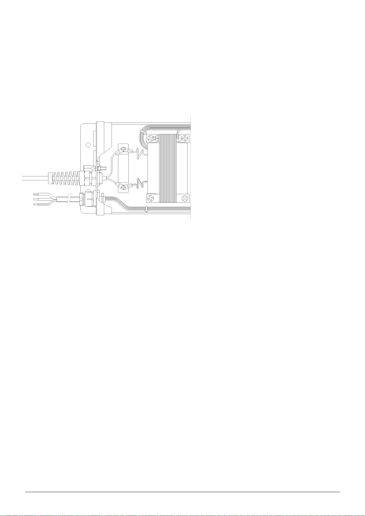
5.2.2. Fitting the air gun
1. Remove the lid from the power unit.
2. Remove one of the central blind glands from the rear of the box.
3. Fit the gland with the air gun cable into this opening.
4. Connect the wiring of the air gun, using the relevant screws.
5. Tighten the gland pull relief.
6. Place the cover onto the box and tighten it.
connection to Cobra
Important:
Make sure that the HV cable is not looped inside the housing.
5.2.3. Connecting compressed air hose
Important:
The compressed air to be used must be clean, dry and free of oil.
It is recommended to use an air filter.
Use a pressure regulator to adjust the blow-off power.
1. Remove the air connecting nipple from the gun.
2. Wrap sealing tape around the nipple.
3. Turn the nipple into the gun.
4. Connect the air hose to the connecting nipple.
5. Connect the air hose to your compressed air installation.
6. Putting into use
Make sure the gun is supplied with compressed air.
Switch on the power unit.
Point the air gun to the object to be cleaned.
Pull the trigger of the air gun.
Cobra_UM_9752050610_NL_D_GB_F_V2_1 18
Page 20
7. Functional check
The indicator lamp on the power unit is an indication of the available high voltage.
A Simco-Ion bar checker can be used to verify that the high voltage at the emitter point of the
gun is on.
An electrostatic fieldmeter must be used to measure the efficiency of the ionizing air gun.
Measure the charge on the material before and after the gun has been used for blowing off.
The charge measured should have disappeared after cleaning.
8. Maintenance
8.1. Air Gun
Keep the air gun clean and dry.
Periodically check the HV cable for damage.
Occasionally lubricate the valve spindle with a drop of oil.
The gun comes within the scope of the European Work Equipment Directive (89/655EEC and
95/63EEC) and shall be periodically checked according to this standard.
8.2. Power unit
Keep the power unit clean and dry.
It does not contain any parts that require maintenance.
9. Faults
9.1. Power Unit
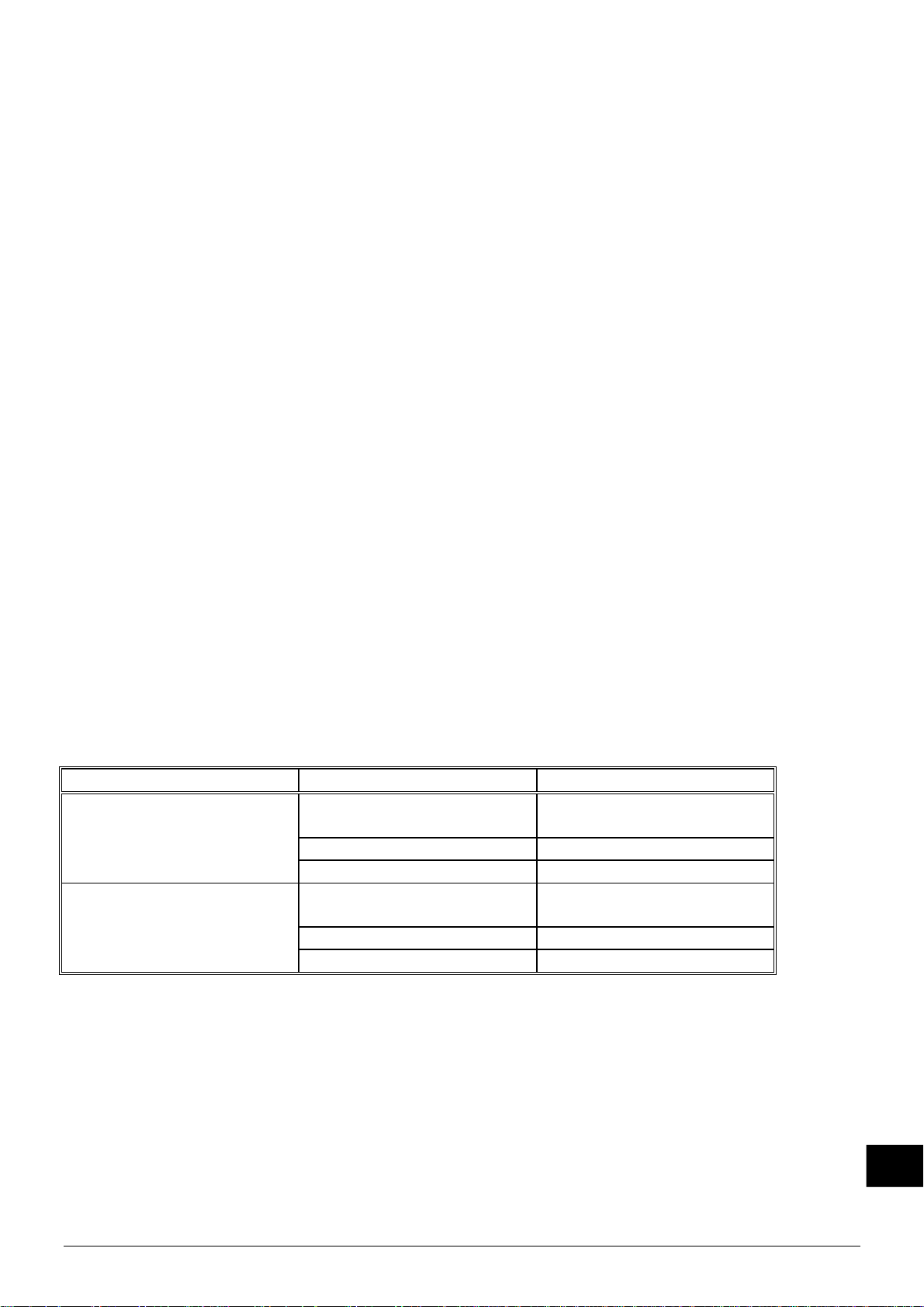
Problem Cause Remedy
Indicator lamps for switch
and HV indicator stay dark.
Power unit is switched off Switch on power unit
Faulty switch Replace switch
HV neon lamp stays dark.
Lamp of switch is lit.
Transformer is defective Replace transformer
Neon lamp is defective Replace neon lamp
table 1 faults
No mains voltage Switch on mains voltage
Short circuit in connected
equipment.
Locate short circuit and
remedy
GB
Cobra_UM_9752050610_NL_D_GB_F_V2_1 19
Page 21
9.2. Air Gun
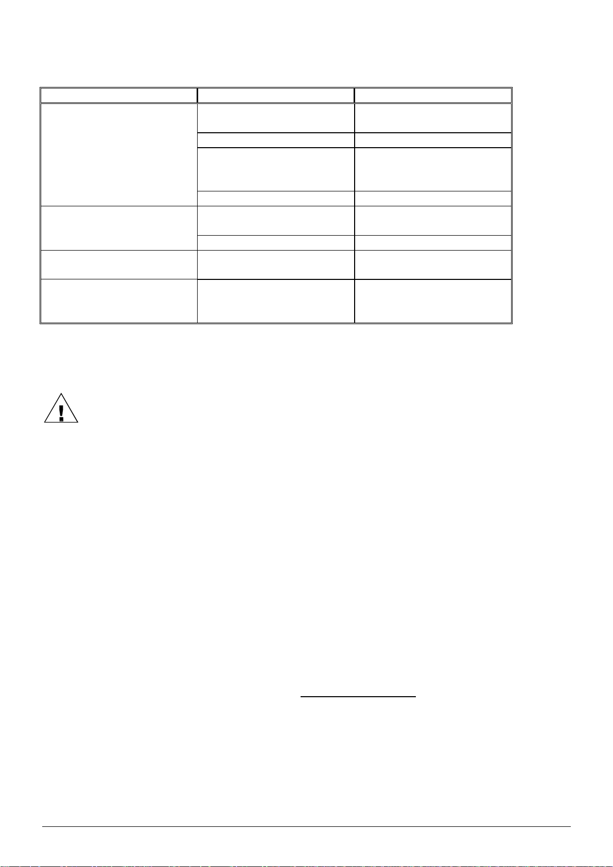
Problem Cause Remedy
Gun does not ionize or ion-
Power unit not switched on Switch on power unit
izes insufficiently
Power unit is defective See power unit manual
HV cable interrupted If possible, shorten HV ca-
ble or return air gun for
repair
Ionizing part is defective Return air gun for repair
No compressed air from
the gun
Compressed air hose not
connected
Connect compressed air
hose
Valve is defective Replace the valve
Insufficient compressed air Compressed air pressure
set too low
Valve remains stuck Valve is subject to exces-
Correctly set the com-
pressed air pressure
Lubricate valve spindle
sive resistance when being
activated
table 2 faults
10. Repair
Warning:
When carrying out work on the equipment: de-energise the equipment.
Repairs shall be made by a skilled engineer.
10.1. Cobra Air Gun
Damaged HV cables may be shortened.
1. Cut off the cable at the damaged spot.
2. Strip the HV cable sheath 40 mm off.
3. Strip the cores 6 mm off.
4. Provide the cores with M3 cable lug.
To order parts, see the spare parts list.
10.2. Power Unit
It is not possible to repair parts of the power unit. To order parts, see the spare parts list.
If the equipment is in need of repair, you may send it to SIMCO (Nederland) B.V.
Request an RMA form by sending an e-mail to service@simco-ion.nl.
Pack the equipment properly and clearly state the reason for return.
Cobra_UM_9752050610_NL_D_GB_F_V2_1 20
Page 22
b
1
Ad
2
2
2
e
393389393
s
N
0
1
2
0
0
G
b
b
w
e
w
V
V
o
a
n
u
r
e
e
a
a
e
a
t
n
C
C
c
p
c
¼
h
c
)
s
1
. Dispo
here to th
1
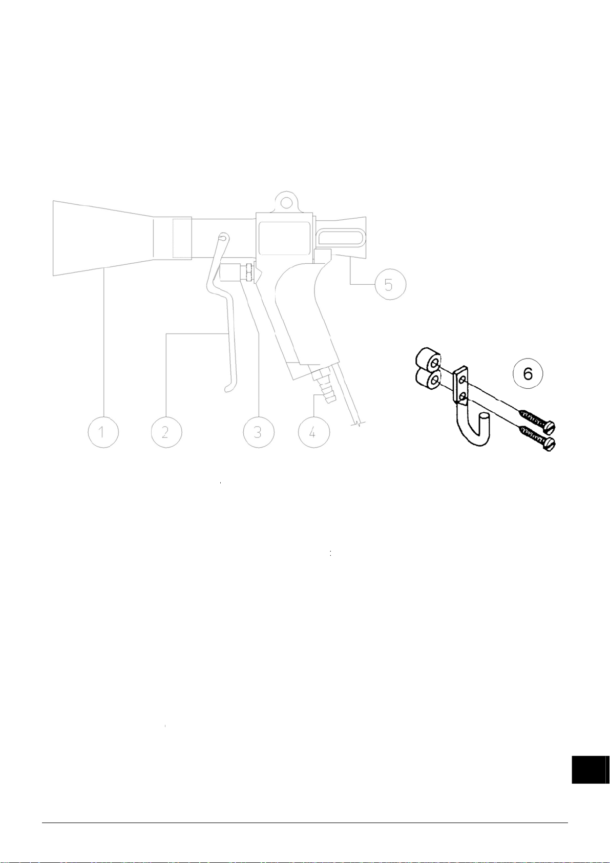
. Spare
1
.1. Spare
al
e applica
parts
parts Co
le local e
ra Air G
vironmen
n
al and oth
er rules w
en dispo
ing of the product.
1
2
3
4
5
5
6
1
.2. Spare
It
m No.
9
.60.25.21
.50.20.01
.99.00.00
.90.60.10
.30.93.22
Co
ra_UM_97520
Item
65.06
65.06
65.00
92.90
65.06
65.06
65.06
o.
.50.3000
.90.1050
.50.3500
.00.1051
.50.1000
.50.1010
.50.0160
parts po
D
8 S
0 H
0 H
0 Pr
7 Tr
50610_NL_D_
er unit
scription
itch with l
indicator
terminal
tection c
nsformer
B_F_V2_1
Desc
Nozzl
Trigg
Valve
Air co
Ioniz
Ioniz
Susp
iption
nnecting
tion part
tion part
nsion bra
mp
neon lam
block with
p for swit
230 V 50
ipple, 8 x
obra with
obra with
ket
contact st
h/neon la
Hz 5,1 kV
“ NPT
20' (6 m)
40' (12 m
rip
mp
able
cable
21
GB
Page 23

SOMMAIRE
1. Introduction ............................................................................................................................ 23
2. Sécurité .................................................................................................................................. 23
3. Application et fonctionnement ................................................................................................ 23
4. Spécifications techniques ....................................................................................................... 24
5. Installation .............................................................................................................................. 24
5.1. Contrôle ........................................................................................................................... 24
5.2. Installation ....................................................................................................................... 24
5.2.1. Montage de l’appareil d’alimentation ......................................................................... 24
5.2.2. Branchement du pistolet sur l’appareil d’alimentation ............................................... 25
5.2.3. Branchement de l’air comprimé ................................................................................ 25
6. Mise en service ...................................................................................................................... 25
7. Contrôle du fonctionnement ................................................................................................... 26
8. Entretien ................................................................................................................................. 26
8.1. Pistolet ............................................................................................................................. 26
8.2. Appareil d’alimentation .................................................................................................... 26
9. Pannes ................................................................................................................................... 26
9.1. Appareil d’alimentation .................................................................................................... 26
9.2. Pistolet ............................................................................................................................. 27
10. Réparation ........................................................................................................................... 27
10.1. Pistolet ........................................................................................................................... 27
10.2. Appareil d’alimentation .................................................................................................. 27
11. Mise au rebut ....................................................................................................................... 28
12. Pièces de rechange ............................................................................................................. 28
12.1. Pièces de rechange Pistole à air ionise Cobra .............................................................. 28
12.2. Pièces de rechange appareil d’alimentation .................................................................. 28
Cobra_UM_9752050610_NL_D_GB_F_V2_0 22
Page 24

NOTICE D'UTILISATION PISTOLET A AIR IONISE COBRA
1. Introduction
Lire attentivement les instructions qui suivent avant toute installation et/ou utilisation du
système. Ces instructions doivent être observées pour assurer le bon fonctionnement de
l’équipement et donner droit à sa garantie.
Les stipulations de garantie sont décrites dans les conditions générales de vente de SIMCO
(Nederland) B.V.
2. Sécurité
Le pistolet à air ionisé Cobra est exclusivement destiné à dépoussiérer et neutraliser
simultanément des surfaces chargées statiquement.
L’installation électrique et les réparations doivent être réalisées par un électricien qualifié.
En cas d’intervention sur l’équipement: mettre l’équipement hors tension.
Assurer une bonne mise à la terre de l’alimentation.
La mise à la terre est nécessaire pour assurer un bon fonctionnement et prévenir tout choc
électrique en cas de contact.
En cas d'utilisation fréquente du pistolet, il est obligatoire d'utiliser un protecteur antibruit.
L’homologation CE et la garantie de l’appareil sont annulées en cas de modification,
d’adaptation, etc. sans accord préalable écrit ou si des pièces qui ne sont pas d’origine sont
utilisées en cas de réparation.
3. Application et fonctionnement
Le pistolet à air ionisé Cobra s'utilise pour nettoyer des matériaux à jet d'air tout en les neutralisant. Grâce au grand débit d’air projeté, le pistolet convient au nettoyage à jet d’air des grandes
surfaces.
Le pistolet à air ionisé Cobra est un pistolet à air comprimé doté d’une pointe ionisante dans le
bec à air. Le pistolet doit être branché sur un appareil d'alimentation Simco-Ion. Cet appareil
d’alimentation génère la haute tension pour la pointe ionisante.
Le Cobra produit un courant d'air fortement chargé d'ions positifs et négatifs. Si ce courant d’air
est dirigé sur une surface présentant une charge électrostatique, un échange d'électrons se
produit et par conséquent une neutralisation de la surface qui est en même temps nettoyée.
Ceci élimine le risque d'un nouvel effet d'attraction des poussières chassées.
Grâce à l’effet de venturi du pistolet, le débit d’air projeté est d’environ 5,5 plus volumineux que
la quantité d’air comprimé utilisée.
Le modèle du bec permet de créer un large courant d'air, capable de nettoyer une grande surface en une seule passe.
Cobra_UM_9752050610_NL_D_GB_F_V2_1 23
F
Page 25
4. Spécifications techniques
Tension d’opération: env. 5,1 kV ca
intensité max. à la pointe 0,25 mA
Appareil d'alimentation : A2A5G pour 230 V réf. : 08.05.25.5700
Agent de pression : air ou azote
raccord à air : ¼ “ BSP, diamètre intérieur de tuyau 9 mm minimum
consommation d’air: 400 l/mn à 3,5 bars
625 l/mn à 7 bars
Déplacement d'air: 2250 l/mn à 3,5 bars
3700 l/mn à 7 bars
Niveau sonore: 92 dB à 2 bars
(mesuré à une distance 96 dB à 4 bars
de 30 cm du pistolet) 101 dB à 7 bars
5. Installation
5.1. Contrôle
- A la livraison, contrôler que le pistolet Cobra n'a pas été endommagé dans le transport et
que sa version est bien celle commandée.
- Vérifier que les données de la fiche de colisage correspondent aux caractéristiques du produit livré.
- Contrôlez si la tension indiquée sur la plaque signalétique correspond à la tension
d’alimentation.
En cas de problèmes et/ou de doute:
Contactez Simco-Ion ou son agent dans votre région.
5.2. Installation
5.2.1. Montage de l’appareil d’alimentation
Attention:
L’installation électrique doit être réalisée par un électricien qualifié.
En cas d’intervention sur l’équipement: mettre l’équipement hors tension.
- Installer / brancher l’appareil d’alimentation à l’endroit souhaité, de façon à ce que le
commutateur et le voyant néon soient bien accessible et visible.
- Fixer l’appareil d’alimentation moyennant les trous de fixation dans la plaque de fond.
- Poser le cordon de raccordement vers le point de branchement au réseau.
- Brancher le cordon de raccordement ou y prévoir une fiche.
Important:
Assurez une bonne mise à la terre de l’équipement. La mise à la terre est nécessaire
pour assurer un bon fonctionnement et prévenir tout choc électrique en cas de contact.
Cobra_UM_9752050610_NL_D_GB_F_V2_1 24
Page 26
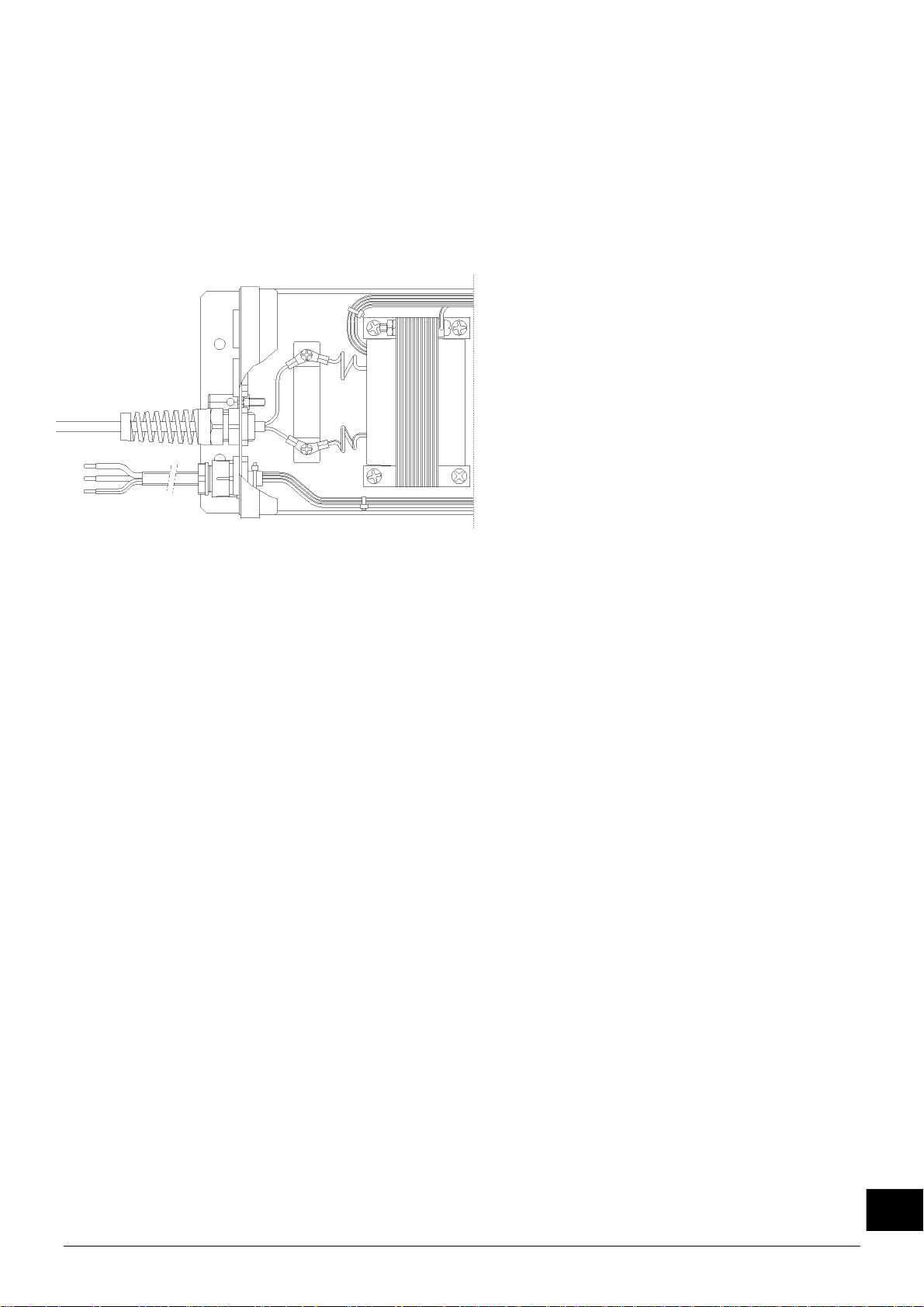
5.2.2. Branchement du pistolet sur l’appareil d’alimentation
1. Enlever le couvercle de l’appareil d’alimentation.
2. Enlever un des presse-étoupe borgnes centraux de la paroi arrière de l’armoire.
3. Y monter le presse-étoupe avec le câble du pistolet.
4. Fixer chacun des conducteurs du pistolet sous une vis de connexion.
5. Serrer l’allégement de traction du presse-étoupe.
6. Remettre le couvercle sur l’armoire et le visser.
branchement Cobra
Important:
Ne pas poser le câble HT dans l’armoire en boucle.
5.2.3. Branchement de l’air comprimé
Important:
L’air comprimé à utiliser doit être propre, sec et exempte d’huile.
L’emploi d’un filtre à air est préconisé.
Utiliser le régulateur de pression pour régler la force de soufflage.
1. Enlever le raccord à air du pistolet.
2. Envelopper du ruban d’étanchéité autour du raccord.
3. Visser le raccord dans le pistolet.
4. Brancher le tuyau à air flexible sur le raccord.
5. Brancher le tuyau à air flexible sur le groupe à air comprimé.
6. Mise en service
Veiller à ce que le pistolet soit alimenté en air comprimé.
Mettre l’appareil d’alimentation en circuit.
Diriger le pistolet sur l'objet à nettoyer.
Manipuler la gâchette du pistolet.
Cobra_UM_9752050610_NL_D_GB_F_V2_1 25
F
Page 27
7. Contrôle du fonctionnement
Le voyant sur l’appareil d’alimentation indique si la haute tension existe. La présence de haute
tension sur la pointe ionisante du pistolet peut être contrôlée au moyen d’un testeur à barre
Simco-Ion. L’efficacité d’un pistolet à air ionisé doit être établie avec un appareil de mesure de
champs électrostatiques. Mesurer la charge sur le matériau avant et après le passage du pistolet. La charge mesurée doit avoir disparue après le soufflage.
8. Entretien
8.1. Pistolet
Assurer que le pistolet reste propre et sec.
Contrôler le câble HT périodiquement pour des endommagements.
Mettre de temps en temps une gouttelette d’huile sur la tige de la soupape.
Le pistolet est régi par la Directive européenne ‘Equipements de travail’ (89/655CEE et
95/63CEE) et doit être contrôlé périodiquement en vertu de cette norme.
8.2. Appareil d’alimentation
- Assurer que l’appareil d’alimentation reste propre et sec.
- Il ne contient pas d’éléments demandant de l’entretien.
9. Pannes
9.1. Appareil d’alimentation
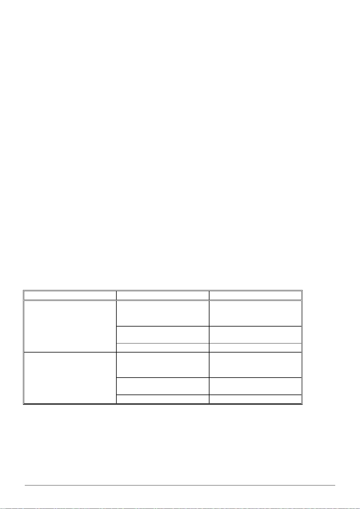
Problème Cause Solution
Voyants commutateur et
indication HT ne s’allument
pas
Appareil d’alimentation
Commutateur défectueux Remplacer le commutateur
Voyant néon (indication de
HT) n’est pas allumé.
Voyant commutateur est
allumé. Le transformateur est dé-
Voyant néon défectueux Remplacer le voyant néon
Tableau 1 Pannes
Pas de tension
d’alimentation
hors circuit
Court-circuit en équipe-
ment connecté
fectueux
Mettre la tension
d’alimentation en circuit
Mettre l’appareil
d’alimentation en circuit
Chercher et réparer le
court-circuit
Remplacer le transformateur
Cobra_UM_9752050610_NL_D_GB_F_V2_1 26
Page 28
9.2. Pistolet
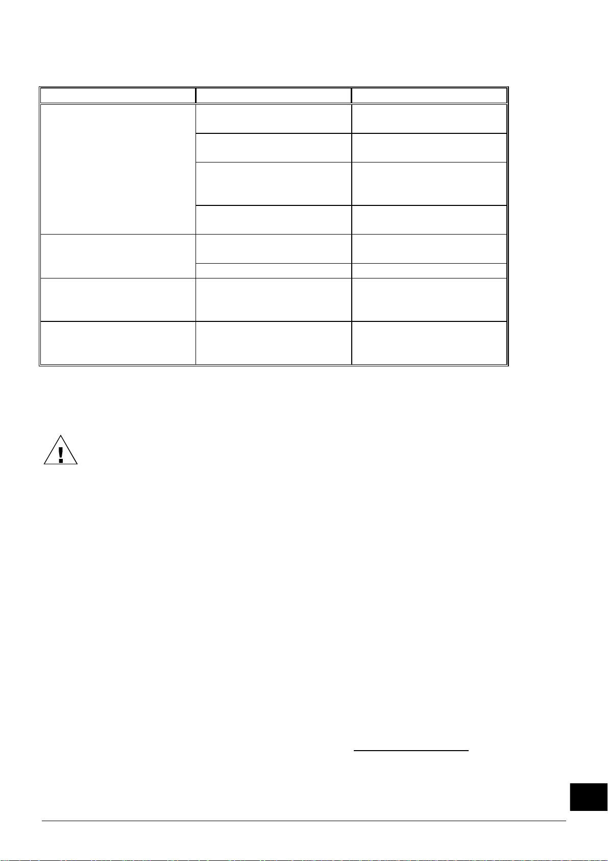
Problème Cause Solution
L’ionisation par le pistolet
est nulle ou insuffisante.
Appareil d’alimentation en
Appareil d’alimentation pas
en circuit
panne
Mettre l’appareil
d’alimentation en circuit
Voir la notice d’utilisation
de l’appareil d’alimentation.
Rupture du câble HT Raccourcir le câble HT si
possible ou retourner le
pistolet pour réparation.
Partie ionisante en panne Retourner le pistolet pour
réparation.
Le pistolet ne projette pas
Air comprimé pas branché Brancher l’air comprimé.
d’air comprimé.
Soupape défectueuse Remplacer la soupape.
Pression d’air insuffisante La pression d’air a été
ajustée à une pression trop
Ajuster la pression d’air à
la valeur correcte.
faible:
La soupape se grippe. La soupape rencontre trop
de résistance lorsqu’elle
Lubrifier la tige de la soupape.
est enfoncée.
Tableau 2 Pannes
10. Réparation
Attention:
En cas d’intervention sur l’équipement: mettre l’équipement hors tension.
La réparation doit être réalisée par un électricien qualifié.
10.1. Pistolet
Un câble HT endommagé peut être raccourci s’il y a lieu.
1. Couper le câble à l’endroit endommagé.
2. Dénuder la gaine de la câble HT sur 40 mm.
3. Dénuder les conducteurs sur 6 mm.
4. Munir les conducteurs d’une cosse de câble M3.
Pour la commande de pièces, voir la liste de pièces de rechange.
10.2. Appareil d’alimentation
L’appareil d’alimentation ne comporte pas d’éléments pouvant être réparés. Pour la commande
de pièces, voir la liste de pièces de rechange.
Si une réparation est nécessaire, renvoyez l'appareil à SIMCO (Nederland) B.V.
Pour ce faire, demandez un formulaire RMA par e-mail à service@simco-ion.nl.
Emballez-le solidement et indiquez clairement la raison du retour.
F
Cobra_UM_9752050610_NL_D_GB_F_V2_1 27
Page 29
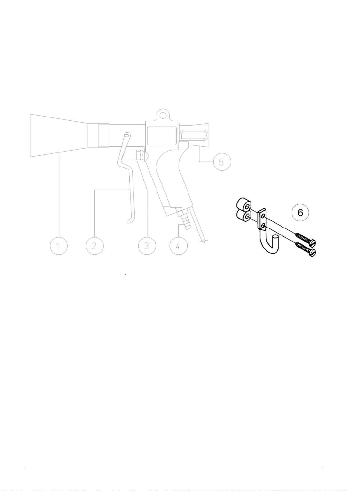
b
1
1
b
2
2
2
é
393389393
a
s
s
s
s
0
1
2
0
0
G
h
a
a
e
o
o
o
a
a
v
o
r
e
a
o
a
u
n
b
m
e
x
p
)
n
m
t
o
c
o
s
r
T
a
u
a
. Mise
O
server le
1
. Pièce
1
.1. Pièce
u rebut
lois natio
de rec
de rech
nales en
ange
nge Pist
igueur en
le à air io
cas de mi
nise Cob
e au reb
a
t de l’app
reil.
1
2
3
4
5
5
6
1
.2. Pièce
R
férence
9
.60.25.21
.50.20.01
.99.00.00
.90.60.10
.30.93.22
Co
ra_UM_97520
Référ
65.06
65.06
65.00
92.90
65.06
65.06
65.06
ence
.50.3000
.90.1050
.50.3500
.00.1051
.50.1000
.50.1010
.50.0160
de rech
D
8 C
0 V
0 B
0 C
7 Tr
50610_NL_D_
nge app
scription
mmutate
yant néo
rne HT à
pot com
nsformat
B_F_V2_1
Desc
Bec
Gâch
Soup
Racc
Câble
Câble
Etrier
iption
tte
pe
rd à air 8
20’ (6m)
40’ (12m
de suspe
reil d’ali
r à voyan
d’indicati
ande de
utateur/v
ur 230 V
x ¼ “ NP
our Cobr
pour Cob
sion
entation
n de HT
ontact
yant néon
50 Hz 5,1
ra
kV
28
 Loading...