

Page 1
IONIZATION SOLUTIONS
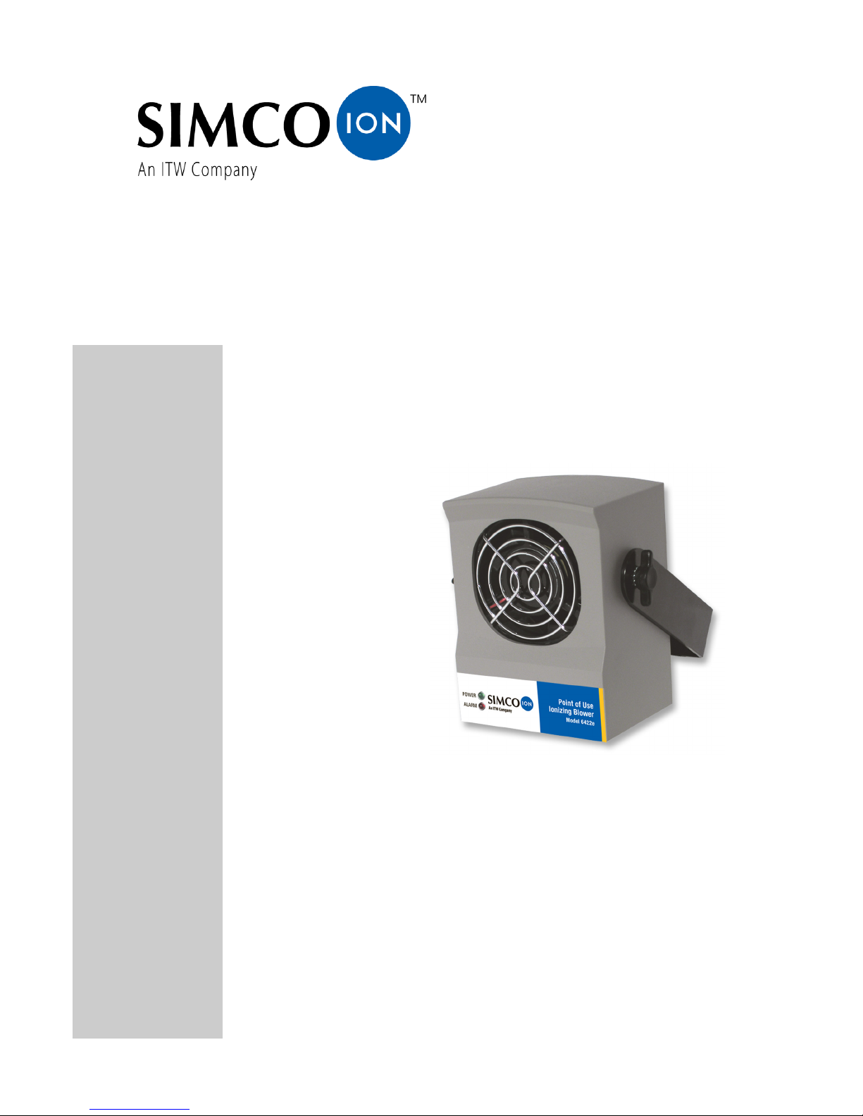
Point of Use
Ionizing Blower
Model 6422e/6422e-AC
User’s Manual
Page 2

19-6422-M-01 Rev 4
About Simco-Ion
Simco-Ion develops, manufactures, and markets system solutions
to manage electrostatic charge. As the world's largest provider of
electrostatics management products and services, Simco-Ion
improves its customers' business results by providing a total
solution to their electrostatic discharge and electromagnetic
interference challenges. Simco-Ion Technology Group is a division
of Illinois Tool Works (ITW), located in Alameda, California. For
more information about Simco-Ion visit www.simco-ion.com or call
800-367-2452. Simco-Ion is ISO 9001 and ANSI ESD S20.20
certified.
© 2013 Simco-Ion
Page 3

19-6422-M-01 Rev 4
Contents
1 Description .......................................................................... 1
1.1 Point of Use Ionizing Blower ................................................................... 2
1.2 IsoStat® Technology............................................................................... 3
1.3 Performance ........................................................................................... 4
1.4 Power Requirements .............................................................................. 5
2 Setup & Operation.............................................................. 7
2.1 Box Contents .......................................................................................... 8
2.2 Blower Placement ................................................................................... 9
2.3 Power Connections............................................................................... 12
2.4 FMS Connection ................................................................................... 15
2.5 Turning on the Blower........................................................................... 17
2.6 Alarms................................................................................................... 18
3 Maintenance ...................................................................... 19
3.1 Maintenance Requirements.................................................................. 20
3.2 Cleaning the Chassis............................................................................ 21
3.3 Cleaning the Emitter Points .................................................................. 22
3.4 Auto-Clean System................................................................................ 23
4 Specifications................................................................... 25
5 Warranty & Service .......................................................... 27
Page 4

19-6422-M-01 Rev 4 1
1
Description
1.1 Point of Use Ionizing Blower
1.2 IsoStat® Technology
1.3 Performance
1.4 Power Requirements
Page 5
19-6422-M-01 Rev 4 2
1.1 Point of Use Ionizing Blower
The Point of Use Ionizing Blower Model 6422e is a compact ionizing
Blower that controls static discharge in areas where static build-up
can cause contamination, ESD, material-handling problems, or
microprocessor lock-up. The internal emitter points are
electrostatically shielded to eliminate field-induced charging.
Steady-state DC ion emission provides fast discharge with low
airflow, allowing less disturbance of delicate product.
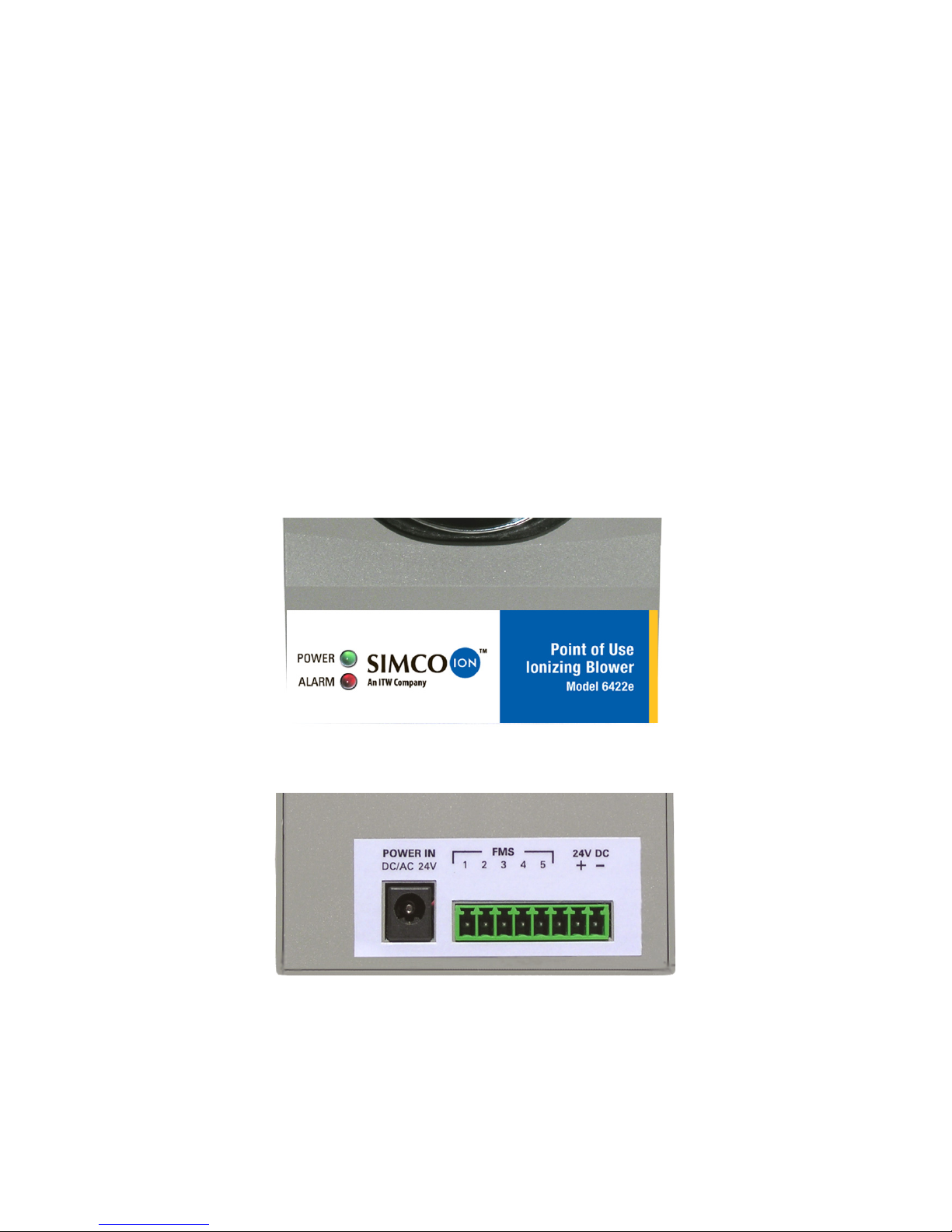
The Model 6422e has a red alarm indicator LED on the front of the
chassis. The eight-pin terminal strip on the back of the unit provides
a 4-20 mA current loop and relay output connection to your facility
monitoring system (FMS) in addition to the 24 VDC input
connection.
Figure 1. Front of the Model 6422e
Figure 2. Back of Model 6422e
The Model 6422e-AC is the same as the Model 6422e with the
addition of our Auto-Clean System as described in Section 3.4 on
page 23.
Page 6

19-6422-M-01 Rev 4 3
1.2 IsoStat® Technology
IsoStat technology makes Simco-Ion blowers the most reliable
ionizers available. IsoStat enables operation without grounding
wires or cables while still maintaining ionizer balance. The 6422e
Blower’s internal emitter points are electrostatically shielded to
eliminate field-induced charging. Steady-state DC ion emission
provides fast discharge with low airflow for less disturbance of
delicate product.
Ionizers incorporating IsoStat technology never need calibration
and require very little maintenance. IsoStat is based on a law of
physics, Conservation of Charge, which states that charge cannot
be created or destroyed in an isolated system. By isolating the
ionizer’s emitter points from ground, IsoStat ensures equal numbers
of positive and negative ions.
Page 7

19-6422-M-01 Rev 4 4
1.3 Performance
The 6422e Blower will reduce a static charge of ±1,000V down to
100V in approximately four seconds at a distance of 1 ft. (30.48
cm)1. See Table 1 for typical discharge times as determined by
distance. Distance is measured from the front center of the Blower.
Ionization balance is better than ±20V at 1 ft. (30.48 cm).
Table 1. Performance
* Testing was performed with a charge plate monitor in accordance
with ionization standard ANSI/ESD STM3.1-2006 of the ESD
Association.
1.
Four-second discharge at one foot distance is when operating Blower
with AC power. Discharge time at one foot when operating Blower with
DC power is five seconds.
Distance Discharge Time
1 ft (30.48 cm) 4 seconds
*
2 ft (61 cm) 10 seconds
3 ft (91.44 cm) 19 seconds
Page 8

19-6422-M-01 Rev 4 5
1.4 Power Requirements
The maximum power requirement for the Model 6422e is 6W. Three
different power supplies are available as options for the Blower,
providing 24 VDC or 24 VAC. The fourth power source is 24 VDC
from your process equipment using the terminal block and eight pin
connector on the rear of the Blower.
Simco-Ion offers three power supplies for use with this product:
• Transformer (p/n 14-1320-01) for use with 120 VAC/60 Hz
systems
• Transformer (p/n 14-1330) for use with 230 VAC/50 Hz systems
• Both 14-1320-01 and 14-1330 transformers provide the Blower
with appropriate 24 VAC
• AC/DC universal power supply (p/n 14-1322) for use with 120/
240 VAC 50/60 Hz provides the Blower with 24 VDC power.
Caution:
The use of improper input voltage may result in poor
performance or damage to the unit.
Damage caused to the power supply from operation in an
environment that exceeds the specified limits will void the
warranty.
Achtung:
Die Verwendung unzulässiger Eingangsspannung kann zu
schlechter Leistung und Beschädigung des Gerätes führen.
Schäden an der Stromversorgung, verursacht durch Betrieb
unter Bedingungen außerhalb der spezifizierten Grenzwerte,
fallen nicht unter die Garantiebestimmungen.
Page 9

19-6422-M-01 Rev 4 6
Page 10

19-6422-M-01 Rev 4 7
2
Setup & Operation
2.1 Box Contents
2.2 Blower Placement
2.3 Power Connections
2.4 FMS Connection
2.5 Turning on the Blower
2.6 Alarms
Page 11
19-6422-M-01 Rev 4 8
2.1 Box Contents
The Model 6422e Blower is supplied with:
• U-shaped mounting bracket (already installed on the blower)
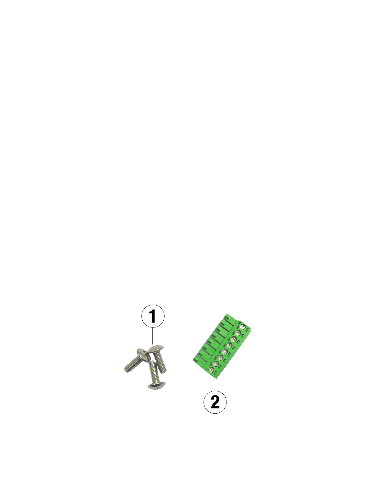
• Three truss-head screws for securing the bracket (Simco-Ion p/
n 28-3369), see item 1 below.
• One 8-pin terminal block plug for connecting to tool power
(Simco-Ion p/n 18-2308), see item 2 below.
• Certificate of Compliance
• This manual
• Power transformer, depending on order:
- 120 VAC transformer (#14-1320-01)
- 230 VAC transformer (#14-1330)
- AC/DC universal power supply (#14-1322)
If you ordered an AC/DC universal power supply (#14-1322), you
will have one of the following plug adapters:
• US wall outlet adapter (p/n 18-0285)
• UK wall outlet adapter (p/n 18-0286)
• Europe wall outlet adapter (p/n 18-0287)
• Australia/China wall outlet adapter (p/n 18-0288)
Figure 3. Mounting Screws and 8-pin Terminal Block
Page 12
19-6422-M-01 Rev 4 9
2.2 Blower Placement
The following points should be considered when positioning the
Model 6422e Blower:
• Keep at least 2 in. (5.1 cm) of free space at the rear of the unit
for unimpeded air intake.
• For fastest decay times, position the Blower close to the target
area where static removal is desired.
• Aim the Blower so that its airflow travels directly to your target.
See Table 1 Performance on page 4 for approximate decay
times versus distance.
• Keep grounded objects away from the ionized airstream to
avoid the possibility of increased offset voltages.
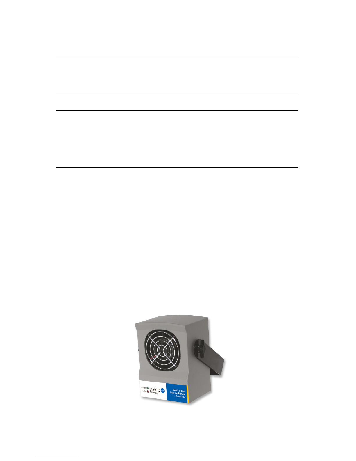
Figure 4. Model 6422e with U-bracket
Caution:
Do not use this Blower in an explosive environment. Poorly
maintained ionizers could produce electric arcs at the emitter
points and lead to detonation in an explosive environment.
Achtung:
Verwenden Sie dieses Gebläse nicht in
explosionsgefährdeten Bereichen. Schlecht gewartete
Ionisatoren können an den Emitter-Punkten Lichtbögen
erzeugen und in explosiver Umgebung eine Explosion
auslösen.
Page 13
19-6422-M-01 Rev 4 10
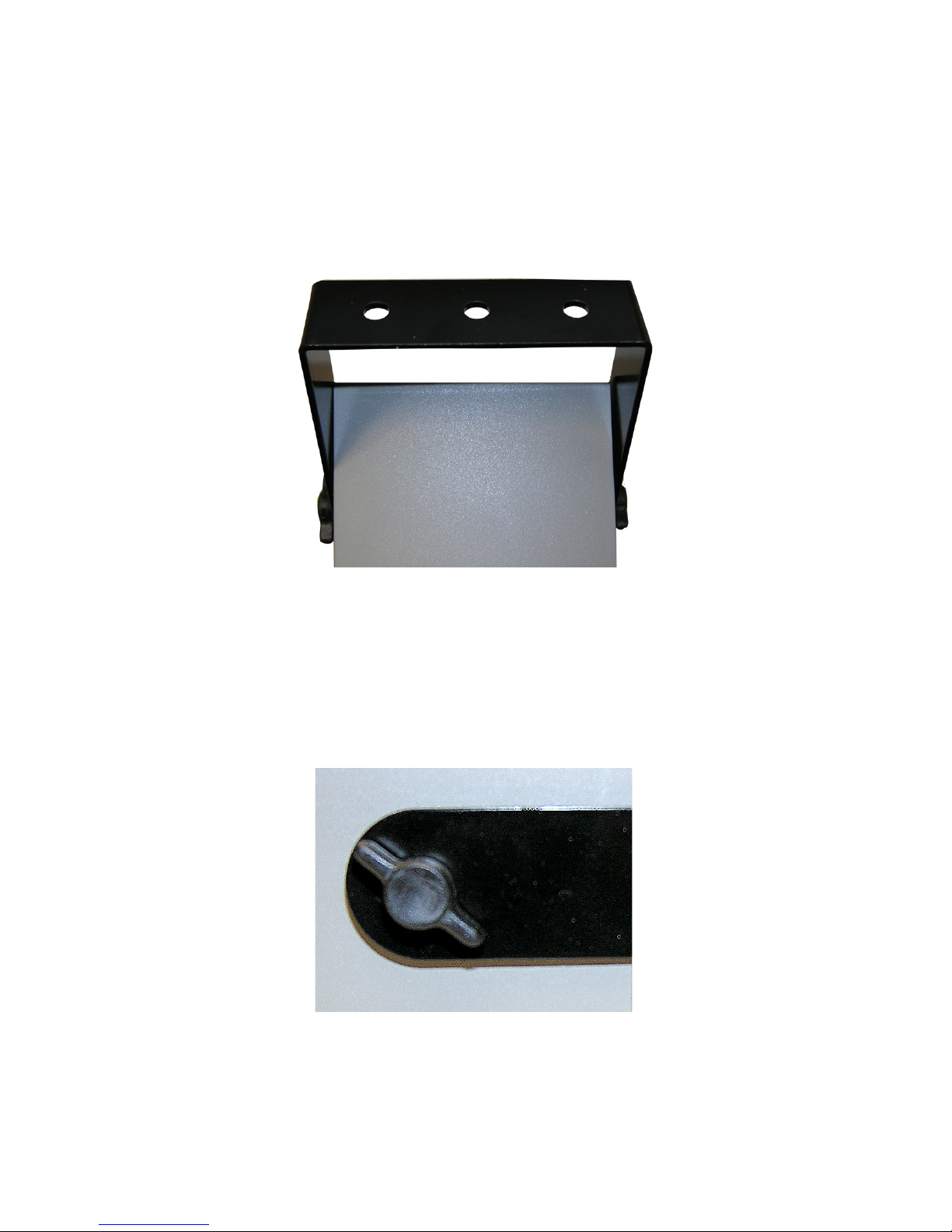
The Model 6422e Blower can be securely mounted using the
supplied U-bracket. It is recommended that the Blower be mounted
using the supplied truss-head screws through the 1/4 in. (6.3 mm)
diameter mounting holes on the bottom of the bracket. The
mounting holes are spaced 1 ft. (25.4 mm) apart on the centerline
of the bracket.
Figure 5. U-bracket Holes for Mounting
The tilt angle of the Blower can be adjusted using the T-knobs on
the sides of the unit. To securely lock the Blower at a desired angle,
replace the T-knobs with the supplied M4x12 mm stainless steel
truss head screws (p/n 28-3369) using a Phillips head screwdriver.
Figure 6. U-bracket Side T-knob for Tilt Adjustment
Page 14

19-6422-M-01 Rev 4 11
Caution:
Do not use screws longer than 12mm to attach brackets to the
threaded inserts in the sides of the Blower.
Achtung:
Verwenden Sie zum Anschrauben von Halterungen an den
seitlich am Gebläse (Blower) befindlichen Gewindeeinsätzen
keine Schrauben, die länger als 12mm sind.
Page 15
19-6422-M-01 Rev 4 12
2.3 Power Connections
The Blower may be powered by an optional 24 VAC 120V or 230V
transformer or a 24 VDC universal AC adapter, sold separately by
Simco-Ion. Plug the transformer or AC adapter into a properly
grounded VAC receptacle with the correct voltage for your power
supply.
Power Supply Connection
Insert the power cable from the transformer or power supply into the
Power In receptacle on the back of the Blower. See the 1.3
Performance and 1.4 Power Requirements sections for additional
information.
AC/DC Adapter Connection
The AC/DC adapter (Simco-Ion p/n 14-1322) output is 24 VDC at
400 mA, maximum.
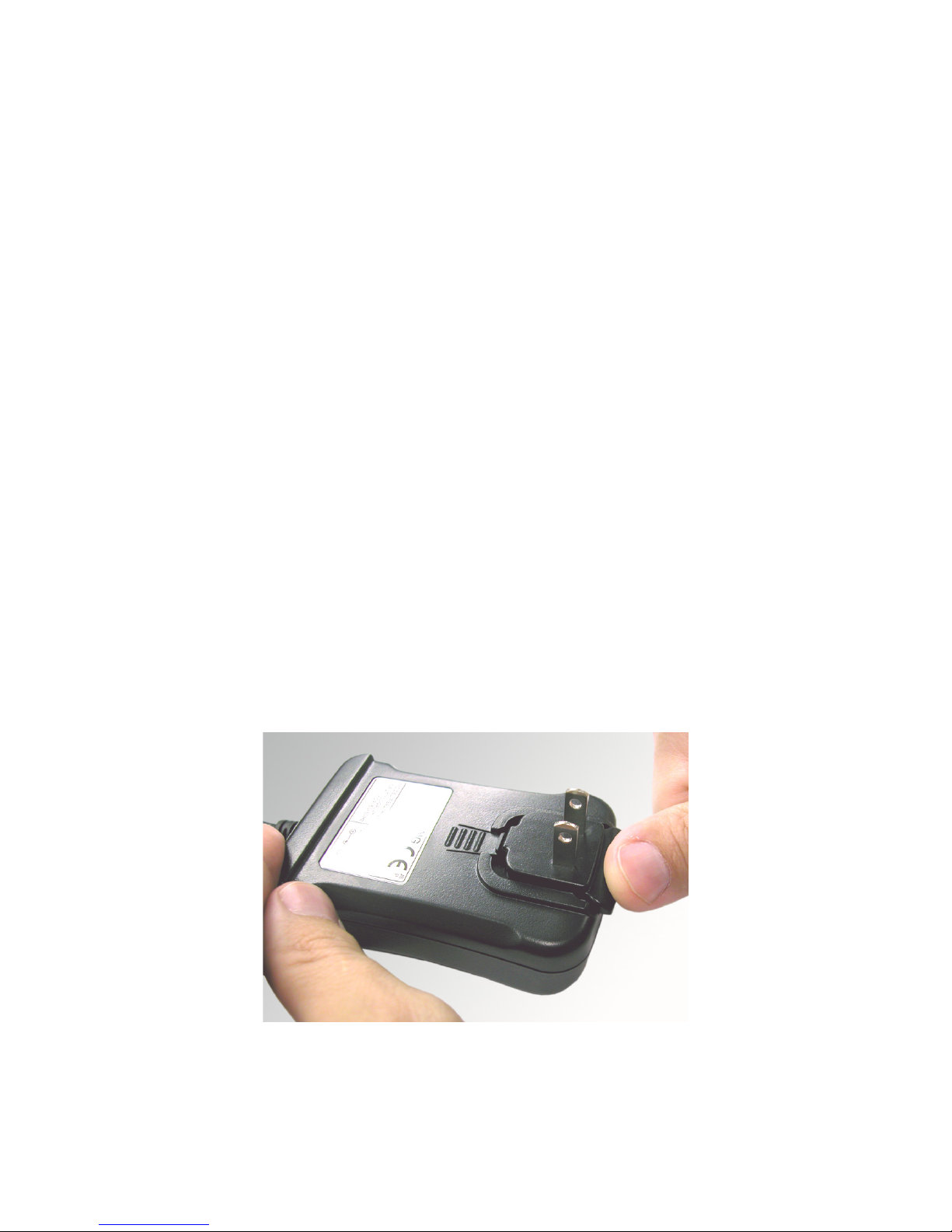
The AC/DC adapter is shipped with its plug adapter uninstalled. To
install the plug adapter, slide it into the bay on the AC/DC adapter.
Push it in until it clicks into place (see Figure 6. U-bracket Side T-
knob for Tilt Adjustment).
Figure 7. Push the Adapter into the AC/DC Power Supply
Page 16
19-6422-M-01 Rev 4 13
Connection to Process Equipment Power
Two active pins on the eight-pin terminal strip on the rear of the
Blower can receive 24 VDC power from your process equipment.
An included terminal block (Simco-Ion p/n 18-2308) is used to
connect 24 VDC power to the Blower from your process equipment.
The connectors are designed to accept wiring between 22 AWG
and 16 AWG.
When wiring the Blower directly to a 24 VDC source, observe the
maximum voltage and power requirements for the unit (24 VDC
[±10%], 400 mA DC maximum) and polarity.
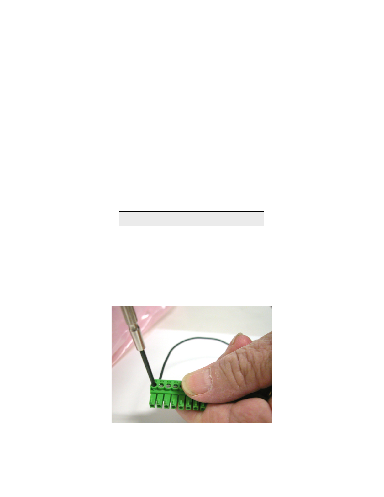
Use a small flatblade screwdriver to secure cables stripped 1/4 in.
(6.3 mm) into the terminal block. See
Figure 8. Flatblade
Screwdriver Securing Connecting Cables below.
Table 2. Model 6422e DC Power on Pins 7,8
Figure 8. Flatblade Screwdriver Securing Connecting Cables
Pins State
8 24 VDC return
7 +24V
6-1 Not used on Model 6422
Page 17
19-6422-M-01 Rev 4 14
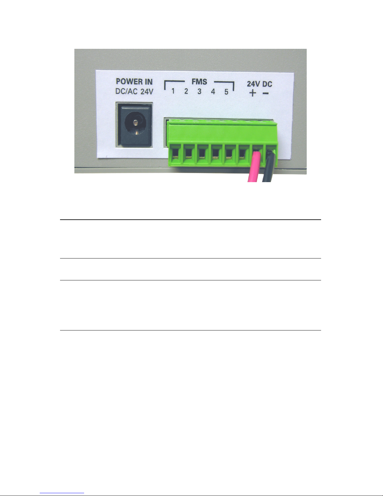
Figure 9. Terminal Block
Caution:
Damage to the product as a result of improper wiring
connections or failure to heed maximum voltage limits will not
be covered by the warranty.
Achtung:
Schäden am Produkt infolge unsachgemäßer Verdrahtung
oder wegen unterlassener Beachtung von maximal
zulässigen Spannungen werden nicht durch die Garantie
abgedeckt.
Page 18
19-6422-M-01 Rev 4 15
2.4 FMS Connection
The Model 6422e Blower provides a non-isolated 4-20 mA current
loop and relay closure output for indicating alarm status to your
process equipment’s facility monitoring system (FMS). In addition to
connecting 24 VDC power into the Blower, the included terminal
block (Simco-Ion p/n 18-2308) connects the Blower to the FMS
using pins 1-5.
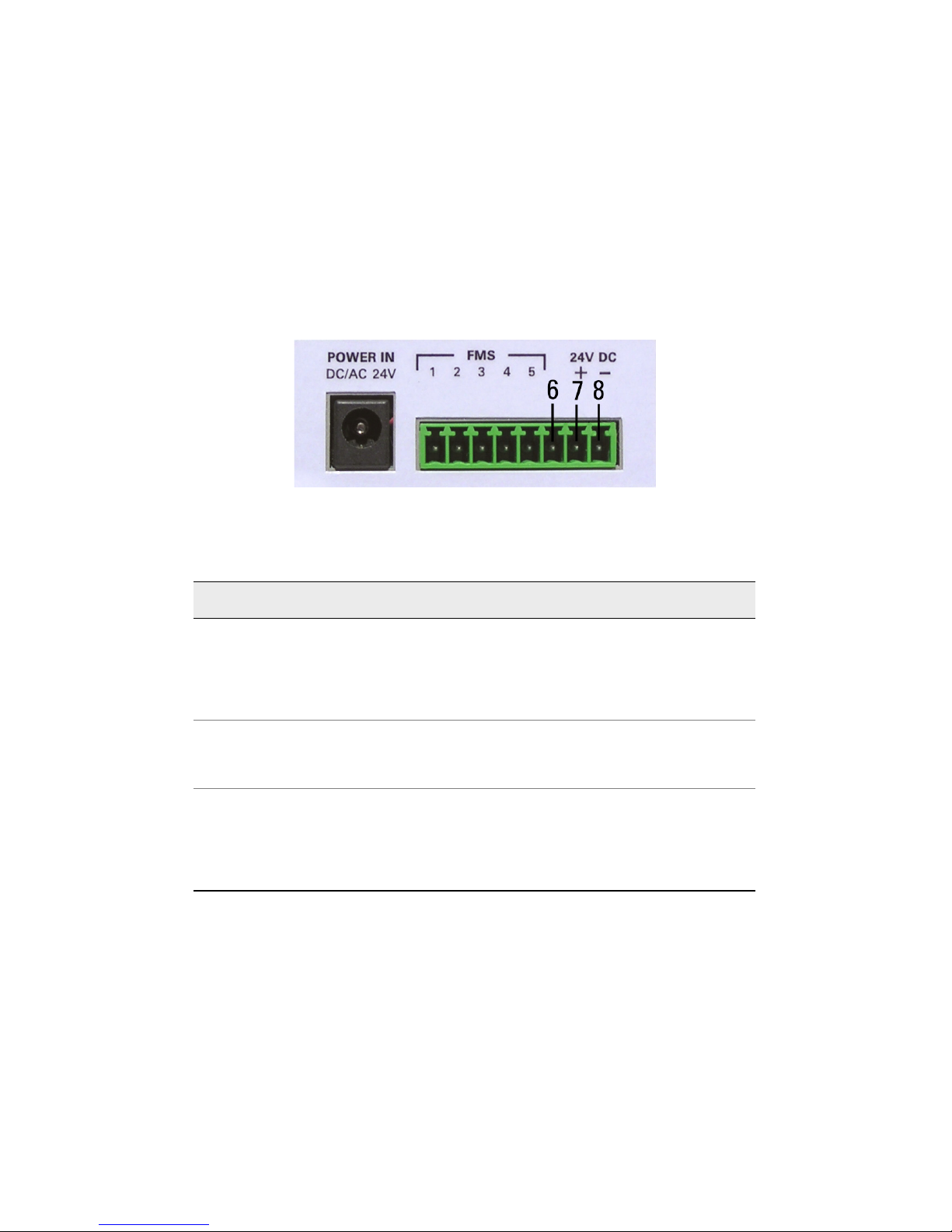
Figure 10. FMS and 24 VDC
Table 3. Descriptions of all 8 Terminal Block Pins
Pin Function(s) Pin Description
24 VDC process equipment
power
8 24 VDC return (Ground)
7 +24V
6 Do not use
4-20 mA current loop
5 - Current loop (Ground)
4 + Current loop
3 Open for active alarm
Relay connections 2 Relay common
1 Closed for active alarm
Page 19

19-6422-M-01 Rev 4 16
Table 4. FMS Output States
Pins Normal State Alarm State No Power
1-2 (relay) Contact open Contact closed Contact closed
2-3 (relay) Contact closed Contact open Contact open
4-5 (Current Loop) 4 mA (OK) 20 mA (Alarm) 0 mA (brownout)
Page 20

19-6422-M-01 Rev 4 17
2.5 Turning on the Blower
The Model 6422e Blower is on as soon as power is applied to the
unit.
Page 21

19-6422-M-01 Rev 4 18
2.6 Alarms
In the event of an alarm, the red LED on the front of the Blower will
light. An alarm indicates that the Blower’s internal high voltage
power circuitry that drives the emitter points is not functioning
correctly. Causes may include low or incorrect input voltage, or a
compromised internal part.
The Blower’s alarm is not a maintenance alert. In most cases,
factory service will be required.
Before contacting Simco-Ion for service, make sure that the Blower
is receiving proper input voltage per specifications.
Caution:
There are no user serviceable parts inside this Blower. Any
unauthorized service will void the warranty and may result in
additional repair charges.
Achtung:
Es gibt keine vom Anwender zu wartenden Teile in diesem
Blower. Nicht autorisierter Service führt zum Erlöschen der
Garantie und kann zu zusätzlichen Reparaturkosten führen.
Page 22

19-6422-M-01 Rev 4 19
3
Maintenance
3.1 Maintenance Requirements
3.2 Cleaning the Chassis
3.3 Cleaning the Emitter Points
3.4 Auto-Clean System
Page 23

19-6422-M-01 Rev 4 20
3.1 Maintenance Requirements
The performance of the Model 6422e Blower is designed to be
maintained primarily by the internal auto-balance circuitry.
Occasional cleaning of the case and emitter points is the only
routine maintenance required. No readjustment of the ionizer is
required after cleaning.
The Blower can be easily removed from the U-bracket by
unscrewing the side knobs.
Recommended Cleaning Materials:
• Cleanroom-compatible cleaning cloths (polyester cloth is
recommended).
• Cleanroom-compatible swabs.
• Cleaning solution of 50% IPA (electronic-grade isopropanol)/
50% de-ionized water.
Page 24

19-6422-M-01 Rev 4 21
3.2 Cleaning the Chassis
Moisten a cloth with the IPA solution. Wipe off any dirt that may
have accumulated on the unit.
Page 25

19-6422-M-01 Rev 4 22
3.3 Cleaning the Emitter Points
Remove power from the Blower. Normally, the emitter points can be
cleaned by using a jet of compressed air to blow off any dirt that may
have accumulated on them. A swab moistened with the IPA solution
may be used if required. If using a swab, gently wipe the tips of the
emitter points until all the dirt is removed.
Wire emitter points should not be bent or moved during cleaning.
After cleaning, make sure that the emitter wires point to the center
of the fan and are on the same horizontal plane.
The Blower uses internally-shielded emitter points that will not
normally require replacement during the normal service life of this
product. If you believe that the emitter points need to be replaced,
contact Simco-Ion Technical Support ([email protected]) for
information.
Caution:
Before performing any maintenance on emitter points, remove
power from the ionizer. Allow a minute for the high voltage
power supply to discharge.
Achtung:
Ziehen Sie vor der Durchführung von Wartungsarbeiten an
Emitter-Punkten den Netzstecker aus dem Ionisator. Lassen
Sie die Hochspannungs-Stromversorgung eine Minute
entladen.
Page 26
19-6422-M-01 Rev 4 23
3.4 Auto-Clean System
The Model 6422e-AC incorporates our Auto-Clean System, a
mechanical device that physically removes particles from emitter
points. Users should consider carefully the appropriateness of using
this device in an ultraclean environment.
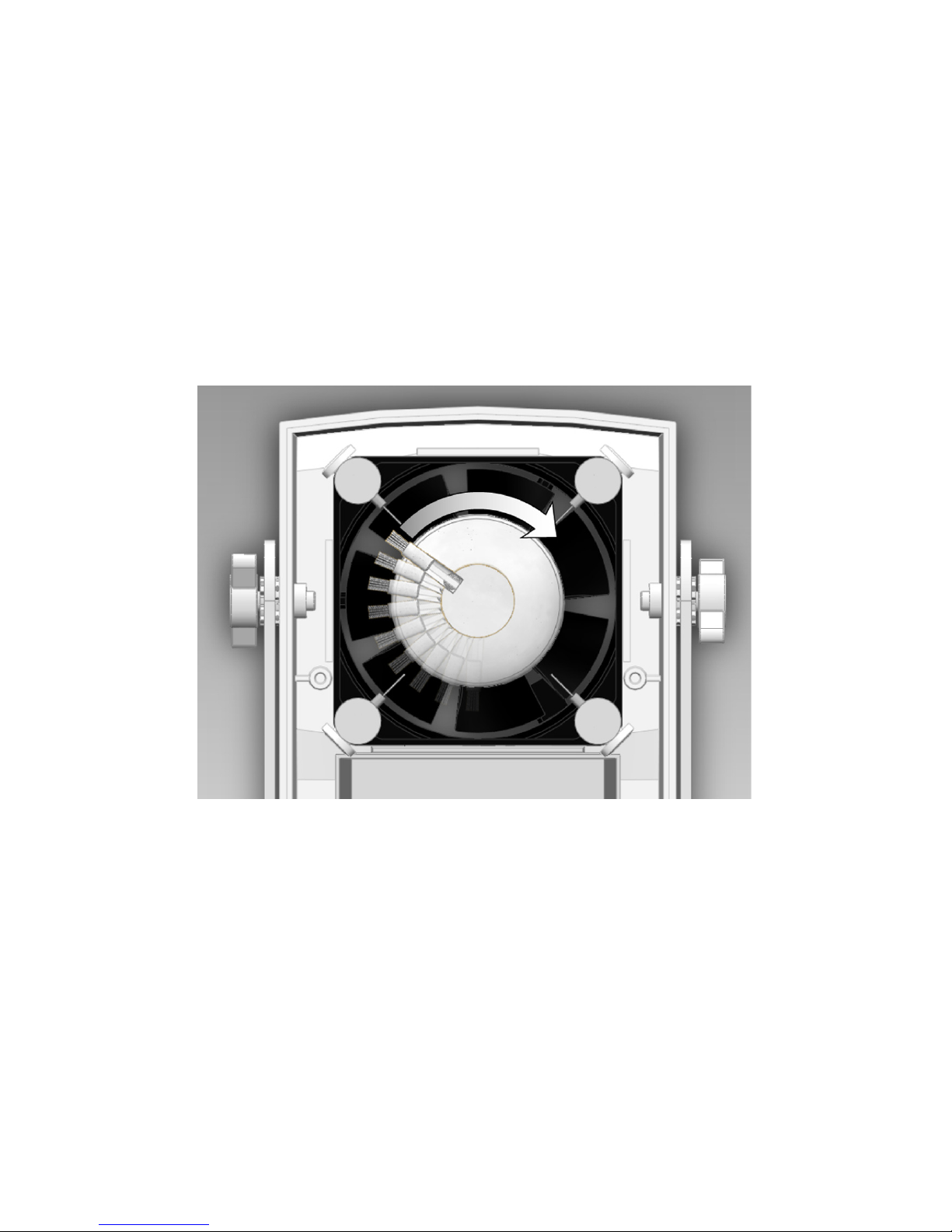
The Auto-Clean System features a brush mechanism that sweeps
the emitter points when the blower is turned off and on. During full
operation of the fan, the brush retracts to prevent emitter point wear.
Figure 11. Auto-Clean System
Remove any contamination-sensitive objects below the blower
before activating the Auto-Clean System. To operate the AutoClean System turn off the blower. The automatic Emitter Point
Cleaner brush will extend as the fan slows to a stop. Allow the fan
to come to a complete stop and then turn the blower back on. Wait
three minutes for any loose particles to be dispersed.
Page 27

19-6422-M-01 Rev 4 24
Activate the Auto-Clean System regularly to prevent excessive build
up of debris. Ion recommends activating the Auto-Clean System at
least once a week. Cleaning schedules will vary depending on
environmental conditions.
The automatic Emitter Point Cleaner can not be
temporarily or permanently removed or de-activated; it is
an integral part of the blower.
Page 28
19-6422-M-01 Rev 4 25
4
Specifications
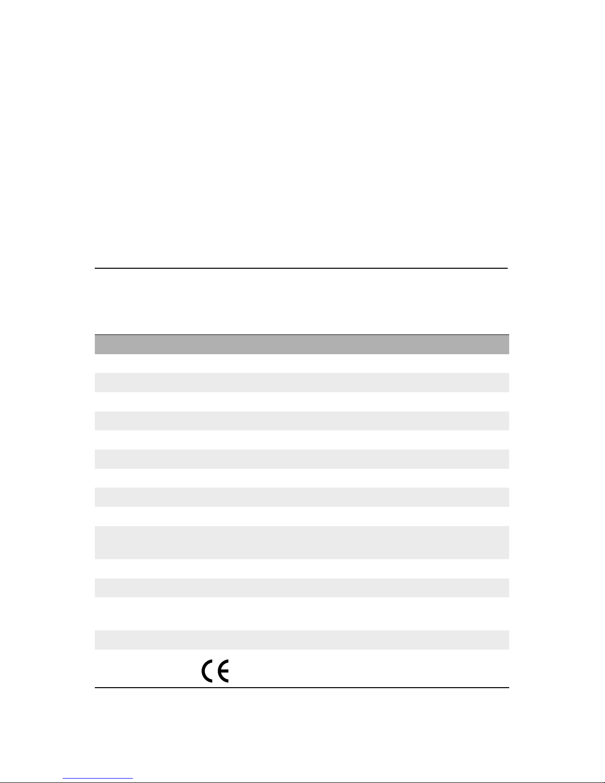
Model 6422 Blower
Input Voltage 24 VDC ±10%, 6W (max) or 24 VAC ±10%; 50/60 Hz, 6W (max)
Output Voltage 5-6 kV at emitter points
Discharge ±1000-100V <4 sec @ 1’, 24 VAC (<5 sec @ 1’, 24 VDC)
Balance ±20V @ 1’ away
Ion Emission Steady-state DC
Emitter Points Tungsten wire; internally shielded
Airflow 23 cfm (typ)
Ozone <0.004 ppm (typ), 24-hour accumulation
LED Indicators Green POWER; red ALARM
Connectors
24 VAC/VDC power input, 8-pin terminal block with 24 VDC input from
process equipment; 4-20 mA current loop FMS output/relay interface
Operating Env. Temperature 10-35°C (50-95°F); humidity 20-60% RH, non-condensing
Mounting U-bracket, factory-installed
Dimensions
With bracket 4.98H x 4.10W x 2.48D in. (126H x 104W x 63D mm); without
bracket 4.37H x 3.26W x 2.48D in. (111H x 83W x 63D mm)
Weight With bracket 12.8 oz (362.9g); without bracket 11.2 oz (317.5g)
Certifications RoHS Compliant
Page 29
19-6422-M-01 Rev 4 26
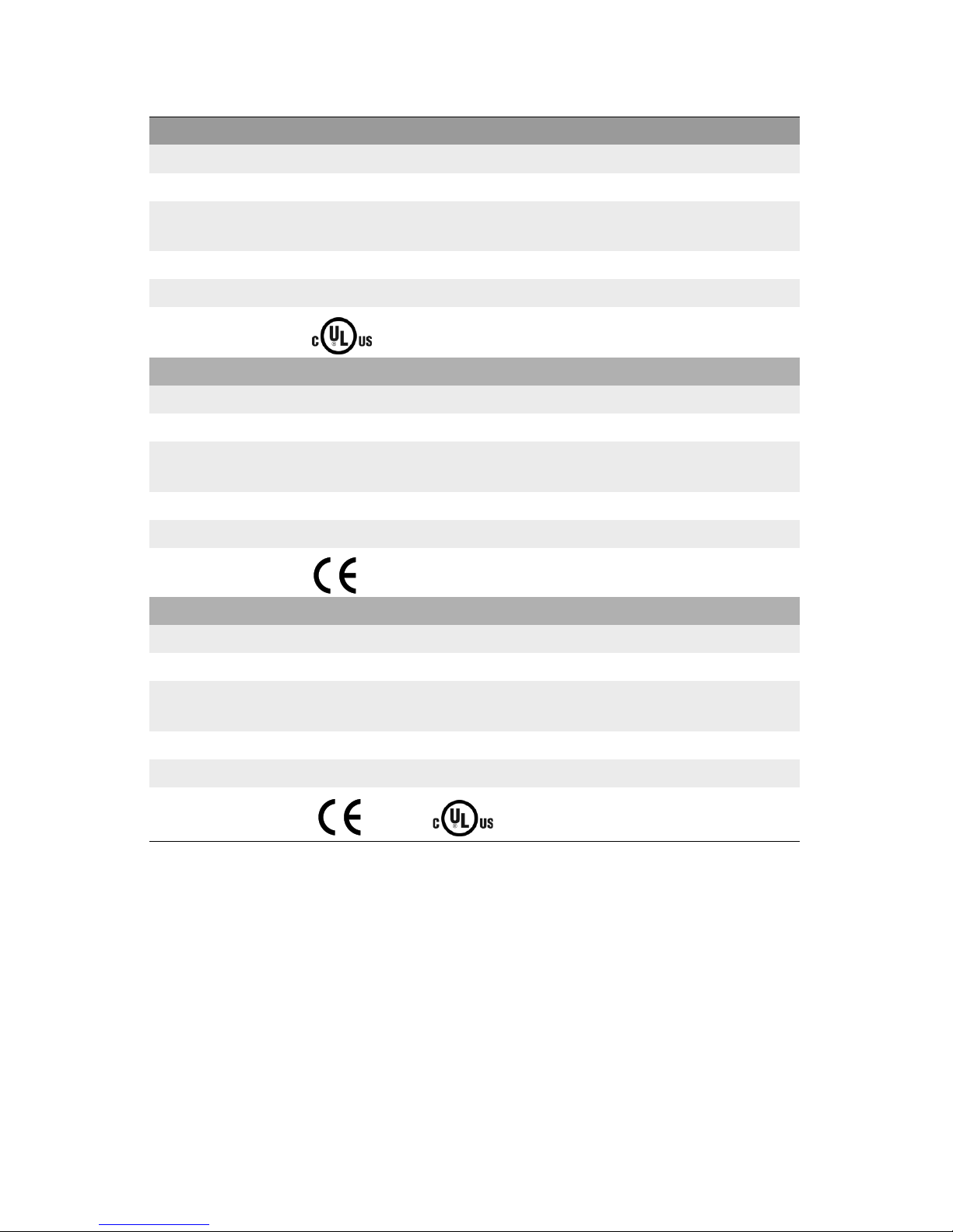
14-1320-01 Transformer
Input Voltage 120 VAC, 60 Hz
Output Voltage 24 VAC, 60 Hz @ 450 mA, ±5%
Short Circuit
Protection
The power supply is provided with protection against short circuit by means
of a primary thermal fuse.
Dimensions 3.4H x 2.3W x 1.9D (87 x 58.5 x 48 mm)
Weight 1 lb (0.45 kg)
Certifications RoHS Compliant
14-1330 Transformer
Input Voltage 230 VAC ±10%, 50 Hz
Output Voltge 24 VAC @ 750 mA, ±5%
Short Circuit
Protection
The power supply is provided with protection against short circuit by means
of a primary thermal fuse.
Dimensions 2.8H x 2.5W x 1.9D in. (72H x 63W x 49D mm)
Weight 0.8 oz (0.36 kg)
Certifications RoHS Compliant
14-1322 AC/DC Adapter
Input Voltage 100-240 VAC ±10%, 50/60 Hz
Output Voltge 24 VDC @ 400 mA
Short Circuit
Protection
The power supply is provided with protection against short circuit by means
of a primary thermal fuse.
Dimensions 1.4H x 2.1W x 3.4L in. (36H x 53W x 86L mm)
Weight 0.25 lb (0.11 kg)
Certifications
RoHS Compliant
Page 30

19-6422-M-01 Rev 4 27
5
Warranty & Service
Simco-Ion provides a limited warranty for the Point of Use Ionizing
Blower Model 6422e. New products manufactured or sold by
Simco-Ion are guaranteed to be free from defects in material or
workmanship for a period of two (2) years from date of initial
shipment. Simco-Ion liability under its new product warranty is
limited to servicing (evaluating, repairing, or replacing) any unit
returned to Simco-Ion that has not been subjected to misuse,
neglect, lack of routine maintenance, repair, alteration, or accident.
In no event shall Simco-Ion be liable for collateral or consequential
damages. Consumable items such as, but not exclusive to, emitter
points, emitter wires, batteries, filters, fuses or light bulbs are only
covered under this warranty if found defective as received with the
new product.
To obtain service under this warranty, please contact Simco-Ion
Technical Support at [email protected] or (510) 217-
0470.
Page 31

19-6422-M-01 Rev 4 28
Page 32

19-6422-M-01 Rev 4 29
Notes
Page 33

19-6422-M-01 Rev 4 30
Notes
Page 34
19-6422-M-01 Rev 4
Technology Group
1750 North Loop Rd., Ste 100
Alameda, CA USA 94502
Tel: 510-217-0600
Fax: 510-217-0484
Toll free:
800-367-2452
Sales services: 510-217-0460
Tech support: 510-217-0470
www.simco-ion.com
 Loading...