

SimAudio 240i Owner's Manual
MOON
240i
Integrated
Amplifier
Owner’s Manual


simaudio.com
Simaudio Ltd., 1345 Newton Road
Boucherville, Québec J4B 5H2 CANADA
Date Code: 03072017

Important Safety Instructions
1. Read these instructions.
2. Keep these instructions.
3. Heed all warnings.
4. Follow all instructions.
5. Do not use this apparatus near water.
6. Clean only with a dry cloth.
7. Do not block ventilation openings. Install in accordance
with the manufacturer’s instructions.
8. Do not install near any heat sources such as
radiators, heat registers, stoves or another apparatus that
produces heat.
9. Do not defeat the safety purpose of the polarized or
grounding type plug. A polarized plug has two blades
with one wider than the other. A grounding-type
plug has two blades and a third grounding prong.
The wide blade or the third prong is provided for safety.
If the provided plug does not fit into the outlet, consult
an electrician for replacement of the obsolete outlet.
10. Protect the power cord from being walked on
or pinched, particularly at plugs, convenience
receptacles, and the point where they exit from
the apparatus. Unplug mains cord during transportation.
11. Only use attachments and accessories specified by
the manufacturer.
12. Use only with the cart, stand, tripod, bracket,
or table specified by the manufacturer or sold with
the apparatus. When a cart is used,
use caution when moving the cart/apparatus
combination to avoid injury from tip over.
13. Unplug this apparatus during lightning storms
or when unused for long periods of time.
14. Refer all servicing to qualified service personnel.
Servicing is required when the apparatus has been
damaged in any way, such as when the power cord
or plug has been damaged; liquid has been spilled or
objects have fallen into the apparatus; or the apparatus
has been exposed to rain or moisture, does not operate
normally, or has been dropped.
15. No naked flame sources, such as candles, should
be placed on the apparatus
WARNING:
TO REDUCE THE RISK OF FIRE OR ELECTRIC SHOCK,
DO NOT EXPOSE THIS APPLIANCE TO RAIN OR MOISTURE.

Important Safety Instructions (continued)
The lightning flash with the arrowhead symbol, within an equilateral triangle, is intended to alert the user
to the presence of uninsulated “dangerous voltage” within the product’s enclosure that may be of sufficient
magnitude to constitute a risk of electric shock to persons.
The exclamation point within an equilateral triangle is intended to alert the user to the presence of important
operating and maintenance (servicing) instructions in the literature accompanying the appliance
Marking by the “CE” symbol (shown left) indicates compliance of this device with the EMC
(Electromagnetic Compatibility) and LVD (Low Voltage Directive) standards of the European Community
PLEASE READ ALL INSTRUCTIONS AND PRECAUTIONS CAREFULLY
AND COMPLETELY BEFORE OPERATING YOUR MOON 240i
1. ALWAYS disconnect your entire system from the AC mains
before connecting or disconnecting any cables, or when
cleaning any component. To completely disconnect this
apparatus from the AC mains, disconnect the power supply
cord plug from the AC receptacle.
2. The MOON 240i must be terminated with a threeconductor AC mains power cord which includes an earth
ground connection. To prevent shock hazard, all three
connections must ALWAYS be used. Connect the MOON
240i only to an AC source of the proper voltage; Both the
shipping box and rear panel serial number label will indicate
the correct voltage. Use of any other voltage will likely
damage the unit and void the warranty
3. AC extension cords are NOT recommended for use with
this product. The mains plug of the power supply cord shall
remain readily accessible.
4. NEVER use flammable or combustible chemicals for cleaning
audio components.
5. NEVER operate the MOON 240i with any covers
removed. There are no user-serviceable parts inside.
An open unit, especially if it is still connected to an AC source,
presents a potentially lethal shock hazard. Refer all questions
to authorized service personnel only.
6. NEVER wet the inside of the MOON 240i with any liquid. If a
liquid substance does enter your MOON 240i, immediately
disconnect it from the AC mains and take it to your MOON
dealer for a complete check-up.
7. NEVER spill or pour liquids directly onto the MOON 240i.
8. NEVER block air flow through ventilation slots or heatsinks.
9. NEVER bypass any fuse.
10. NEVER replace any fuse with a value or type other
than those specified
11. NEVER attempt to repair the MOON 240i. If a problem occurs
contact your MOON dealer.
12. NEVER expose the MOON 240i to extremely high
or low temperatures.
13. NEVER operate the MOON 240i in an explosive atmosphere.
14. ALWAYS keep electrical equipment out of reach of children.
15. ALWAYS unplug sensitive electronic equipment during
lightning storms.
16. WARNING: Do not expose batteries or battery pack
to excessive heat such as sunshine, or fire or the like.

Table of Contents
Introduction / Features 7
Unpacking 8
Installation & Placement 8
Front Panel Controls 9
Phono Input 10
Digital Inputs 10
Software Setup
Renaming an input
Adjusting an input’s oset volume
Disabling an unused input
Using the volume bypass feature
Setting up an input for a MOON CD player
Setting up an input for a MiND Streamer
Setting the power up volume level
Setting up a maximum volume (all inputs)
Setting up the display’s screen saver
Power settings
Blue LED settings
Displaying rmware version
Reset to factory defaults
Rear Panel Connections 20
SimLink
Operating the MOON 240i
Turning on the MOON 240i for the rst time
On and O sequence
Remote Control 22
Remote Control with other MOON components 23
Troubleshooting 23
Specications 24
Quick Reference: Setup Menus Appendix
TM
11
12
13
13
14
15
15
16
16
17
18
18
18
19
20
21
21
21

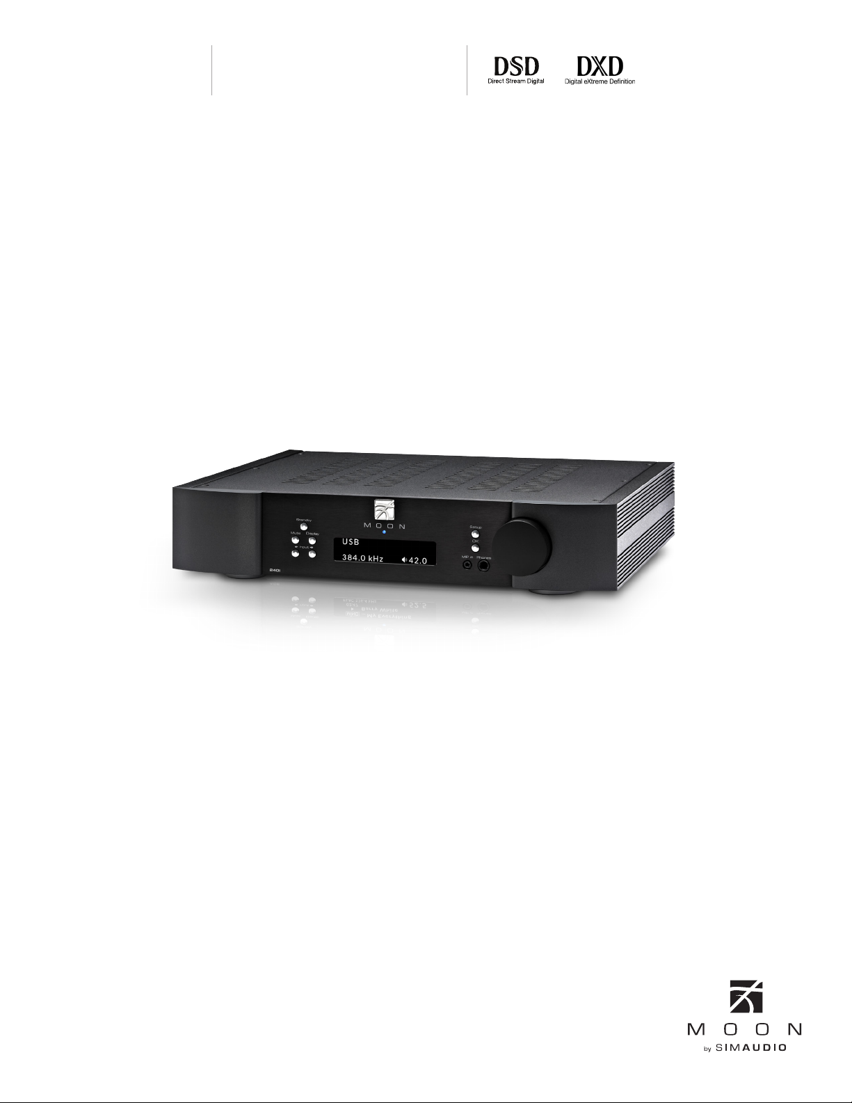
Introduction
Thank you for selecting the MOON 240i as a part
of your music/cinema system. This component has been
designed to offer state-of-the-art high-end performance in
an elegant package, while retaining all the sonic hallmarks
on which Simaudio has made its reputation. We have spared
no effort to ensure that it is amongst the finest in its class.
We have been building high-performance audio equipment
for over 35 years, and the know how gained through our
cumulative experience is an important reason why MOON
products are so musically satisfying.
The performance of your MOON 240i will continue to
improve during the first 400 hours of listening. This is the
result of a “break-in” period required for the numerous high
quality electronic parts used throughout this c omponent.
Before setting up your new 240i, we encourage you to please
read this manual thoroughly to properly acquaint yourself
with its features. We hope you enjoy listening to the MOON
240i as much as the pride we have taken in creating this fine
audio product. We understand the power and emotion
of music and build our products with the goal of faithfully
capturing these elusive qualities. Your MOON 240i
incorporates many significant design features to achieve its
“world class” level of performance.
Headphone output on 1/4” jack located on the front
panel.
OLED type screen (organic light-emitting diode)
Analog inputs are configurable to “HT BYPASS” mode
to accommodate components like a home-theater
processor, whose own volume control is used.
This is sometimes referred to as a “pass-through” input.
Configurable “Standby” modes that will reduce your
power consumption.
RS-232 port for (i) full unsolicited bidirectional feedback
and (ii) firmware updates; IR input for external control
with aftermarket infrared remote control receivers
and SimLink
communications between other MOON components.
Rigid chassis construction to minimize the effects of
external vibrations.
The information contained in this manual is
subject to change without notice. The most current
version of this manual is available on our official website at
http://www.simaudio.com/
TM
controller ports that allow for 2-way
Features
This is an abbreviated list of the more important features:
Fully asynchronous DAC supports native DSD64, DSD128
and DSD256 (USB only) and PCM up to 32-bit/384kHz
including DXD (USB only)
3 line-level inputs including a front-mounted 1/8” mini-
jack for personal media players.
Five(5) digital inputs includes USB (hi-res audio), SPDIF(2),
Optical(2),
Moving magnet phono input for a turntable.
7

Unpacking
The MOON 240i should be removed from its box with care.
The following accessories should be included inside the box with your integrated amplifier:
This owner’s manual
AC power cable
CRM-3 remote control with two CR-2032 batteries
1 spare fast-blow fuse
SimLinkTM / 12V trigger cable
Warranty and product registration information (USA and Canada only)
Once the 240i is unpacked, inspect it thoroughly and report any damage to your dealer immediately. We suggest
that you keep all of the original packaging, storing it in a safe, dry place in case you’re required to transport this
product. The packaging is specially designed to protect the 240i from any potential damage during transit.
Please write the serial number of your new MOON 240i in the space provided below for future reference.
Serial Number
Installation & Placement
The 240i requires reasonable ventilation to maintain an optimum and consistent operating temperature since
it will radiate heat. Consequently, it should be placed in a location with empty space around it for proper heat
dissipation. Maintain a minimum of 4 inches of free space on each side and back, and 9 inches on top. You should
never place another component on top of this unit nor block the vents. Air must be permitted to pass freely through.
You should never place another component on top of this integrated amplifier. As well, it should be placed on a solid level
surface. You should avoid placing it near a heat source or inside a closed cabinet that is not well ventilated as this could
compromise its performance and reliability. The 240i uses a toroidal transformer; even though it is well shielded, you should
not place it too close to source components sensitive to EMI, such as turntables.
If you intend to use the MOON 240i’s USB input connection (PCM or DSD) with a Windows-based computer, you will
need to install our USB HD DSD driver, which can be downloaded from the support section of our website.
MacOS-based computers don’t require any drivers.
8
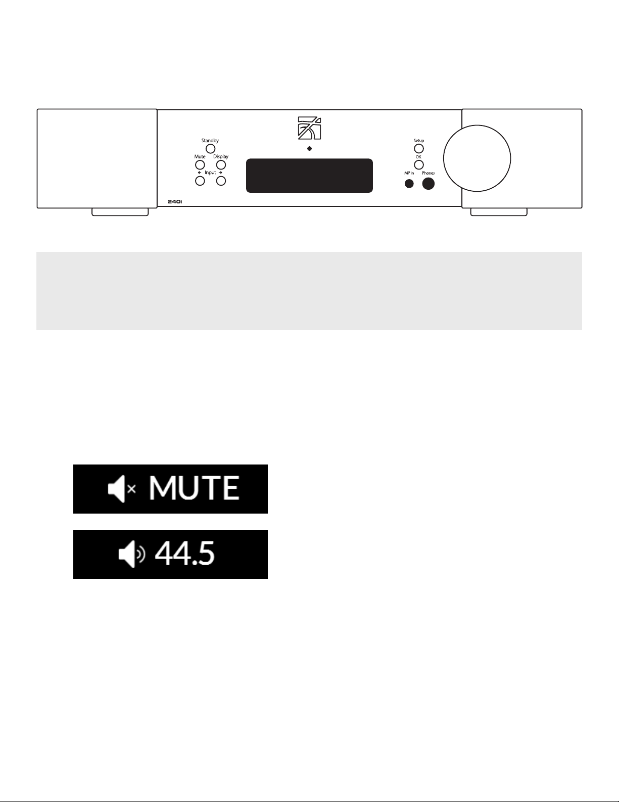
Front Panel Controls
Figure 1: Front panel of the MOON 240i
The front panel will look similar to Figure 1 (above). The “Standby” button places the unit into Standby mode; You can
configure this to your own preferences– refer to the “Power Settings” section of the “Software Setup”. When switching from
“Standby” to the “on” mode (i) Five (5) seconds of animation will appear in the display prior to the 240i being ready for use
and (ii) The blue indicator LED will illuminate unless you have programmed it differently using the “SETUP” software
The “Mute” button mutes the output signal to all outputs.
Pressing the “Mute” button a second time will reinstate the
volume back to its previous level. Below are two (2) screen
capture images that demonstrate what appears on the
display during muting and immediately after unmuting
the output signal:
The “Display” button allows you to adjust the
brightness of the large display window. It also
provides you with the option of turning o the
display. There are three (3) dierent levels of
brightness; The default is high. Pressing the
“Display” button once will decrease the level to the
low setting. Pressing the button again will increase
the brightness to the medium setting. Pressing the
“Display” button a third time returns the display to its
default setting of high. To turn the display o, press
and hold the “Display” button for 2 seconds. When the
display is turned o, it will still come back on briey
whenever you press any of the buttons located
on the front panel or the remote control, using the
previously set brightness level; the display will
automatically turn o again once you are done.
To turn the display back on, simply press and hold
the “Display” button for 2 seconds.
The two (2) buttons labeled “ Input ” allow
you to sequentially scroll, either forward “” or
backward “” through all nine (9) inputs. These inputs
are ordered as follows going forward (): “OPTICAL
1”, “OPTICAL 2”, “SPDIF 1”, “SPDIF 2”, “USB”, “ANALOG 1”,
“ANALOG 2”, “PHONO” and “MP IN”.
The display window will show the currently selected
input. Each type of input has a uniquely respresentative icon, located to the left of the input name, to
help clearly identify it. Here are examples of these
aforementioned inputs.
Note: The two (2) OPTICAL, two (2) SPDIF and two (2)
ANALOG inputs each use the same type of icons:
9
 Loading...