


Induction Heater IH 240
Bedienungsanleitung
Instruction for use
Mode d‘emploi
Manuale d‘instruzioni
Manual de instrucciones

© simatec ag Induktionsheizgerät IH 240 2

Table of contents
EU-Declaration of conformity 17
Safety recommendations 18
1 Introduction 19
1.1 Intended use 19
1.2 Principle of operation 19
2 Technical description 20
2.1 Components 20
2.2 Technical data 21
3 Installation of main plug 21
4 Preparation for use 22
5 Operation 23
5.1 Function of displays 23
5.2 Function of buttons 23
5.3 Temp Mode 24
5.4 Time Mode 25
5.5 Temperature measurement 25
5.6 Change of temperature unit 25
5.7 Demagnetisation 25
5.8 Power level selection 26
6 Safety features 26
7 Troubleshooting 27
8 Spare parts 27
© simatec ag Induction Heater IH 240 16

EU-Declaration of Conformity
We, simatec ag
Stadthof 2
CH-3380 Wangen a. Aare
declare that the
Induction Heater
simatherm IH 240
is designed and manufactured in accordance with
EUROPEAN LOW VOLTAGE DIRECTIVE 73/23/EEC
EMC NORM 89/336/EEC
English
The follwoing norms are used:
Harmonized Norms:
EN 60519-3 :1996
EN 55011
EN 61000-6-2
EN 61000-3-3/3
National Norms:
VDE 0721
Wangen a. Aare, 2005-02-01
Mischa Wyssmann
Managing Direktor / CEO
© simatec ag Induction Heater IH 240 17

Safety recommendations
• Because the IH 240 generates a magnetic field, people wearing a
pacemaker must not be within five meters of the IH 240 during ope ration. Electronic equipment, such as wristwatches, may also be affec ted.
• Follow the operating instructions at all times.
• Be certain that the voltage supply is correct.
• Electrical arcing may occur when a potential difference exists between
the IH 240 and the workpiece. This is not dangerous to human
beings and will not cause damage to the IH 240 or the workpiece.
However, the IH 240 must never be used in areas where there is a
risk of explosion.
• Do not expose the heater to high humidity.
• Never operate the IH 240 without a yoke in position.
• Do not modify the IH 240.
• Use proper handling equipment when lifting heavy workpieces.
• Avoid contact with hot workpieces. Wear the supplied heat resistant
gloves to handle hot workpieces.
© simatec ag Induction Heater IH 240 18

1 Introduction
The simatec IH 240 induction heater is designed to heat bearings that are
mounted with an interference fit onto a shaft. The heat causes the bearing
to expand, which eliminates the need to use force during installation.
A 90 °C temperature difference between the bearing and shaft is generally
sufficient to enable installation. At an ambient temperature of 20 °C,
the bearing must therefore be heated to 110 °C.
1.1 Intended use
The IH 240 has been designed to heat rolling bearings. However, other
metal workpieces that form a closed circuit can also be heated. Examples
of acceptable workpieces include bushings, shrink rings, pulleys, and
gears. All bearings that fit over the inductive coil and between the vertical
supports with the sliding yoke in place can be heated using the IH240.
In addition, smaller bearings can be placed over the sliding yoke. See the
illustration at the beginning of this manual for example.
English
1.2 Principle of operation
The IH 240 generates heat by
means of a large electrical current
that is magnetically induced in
the workpiece by a coil within the
heater. The high voltage, low
current electricity flowing through
the large number of windings in
the inductive coil induces low
voltage, high current electricity in
the workpiece. Because the
workpiece has the electrical
characteristics of a coil with a
single, short-circuited winding,
the high current generates heat
within the workpiece. Because
the heat is generated within the
workpiece, all of the heater
components remain cool.
© simatec ag Induction Heater IH 240 19

2 Description
The heating cycle is electronically controlled either in a TIME MODE,
where the heating time is selected, or in a TEMP MODE where the
desired temperature is selected.
The heater can further be run on 50% capacity when small yokes are used
or when there is a risk for too quick heating of sensitive workpieces (e.g.
bearings with C1 or C2 clearance).
2.1 Components
The induction heater consists of a U-shaped iron core with a large induction
coil on one of its legs. The control electronics sits in a separate control box
on top of the heater.
The temperature is controlled by means of a magnetic probe.
© simatec ag Induction Heater IH 240 20

2.2 Technical data
Voltage (± 9%) 400 V / 50 Hz
460 V / 60 Hz
575 V / 60 Hz
Recommended circuit protection 63 A circuit breaker
Power consumption (maximum) 24 kVA (400 V / 50 Hz)
24 kVA (460 V / 60 Hz)
24 kVA (575 V / 60 Hz)
Temperature control 0–250 °C, in steps of 1°
Probe maximum temperature 250 °C
Time mode 0–60 minutes, in steps of 0.1minute
Power reduction 50%
Demagnetisation, automatic Residual magnetism < 2 A/cm
Overall dimensions 750 x 400 x 935 mm
Area between supports 330 x 355 mm
Coil diameter 186 mm
Weight (with yokes) 300 kg
Workpiece maximum weight 1200 kg
Maximum heating temperature ca. 400 °C
Standard yoke dimensions 100 x 100 x 570 mm
Ø of 142 mm)
(for
English
3 Installation of main plug
Due to the many types of mains plugs, no mains plug is supplied with
the IH 240. A qualified electrician must install a suitable mains plug.
The correct supply voltage is shown in section 2.2. The wires should be
connected as follows:
Colour of IH 240 wire Mains supply terminal
yellow / green ground
brown phase 1
blue phase 2
Connect the IH 240 to only two of the three phases. Verify that the
correct cicuit breaker is installed. See section 2.2 for circuit breaker
specifications.
© simatec ag Induction Heater IH 240 21

4 Preparation for use
• Place the IH 240 in the horizontal position on a stable surface.
• Connect the mains plug to a suitable mains supply.
• For workpieces with an internal diameter large (>186mm) enough to fit
over the inductive coil, follow these steps:
- Place the workpiece over the inductive coil using appropriate
lifting equipment.
- For best performance, adjust the position of the workpiece so
that the inductive coil is in the centre.
- If the sliding yoke is not installed on the IH 240, follow the
steps shown in the illustrations at the beginning of this manual.
Remove the protective film from the bright underside of the
sliding yoke before the first use.
- Slide the sliding yoke to the right so that it completely covers the
top of both vertical supports.
• For workpieces that do not fit over the inductive coil, should be heated on
the horizontal yoke.
• If you will use TEMP MODE, plug the temperature probe into the
connector on the left side of the heater. Place the magnetic end of the
probe on the inner ring of the bearing or on the innermost surface of the
workpiece.
• Switch the IH 240 on using the power switch on the left side.
© simatec ag Induction Heater IH 240 22
5 Operation
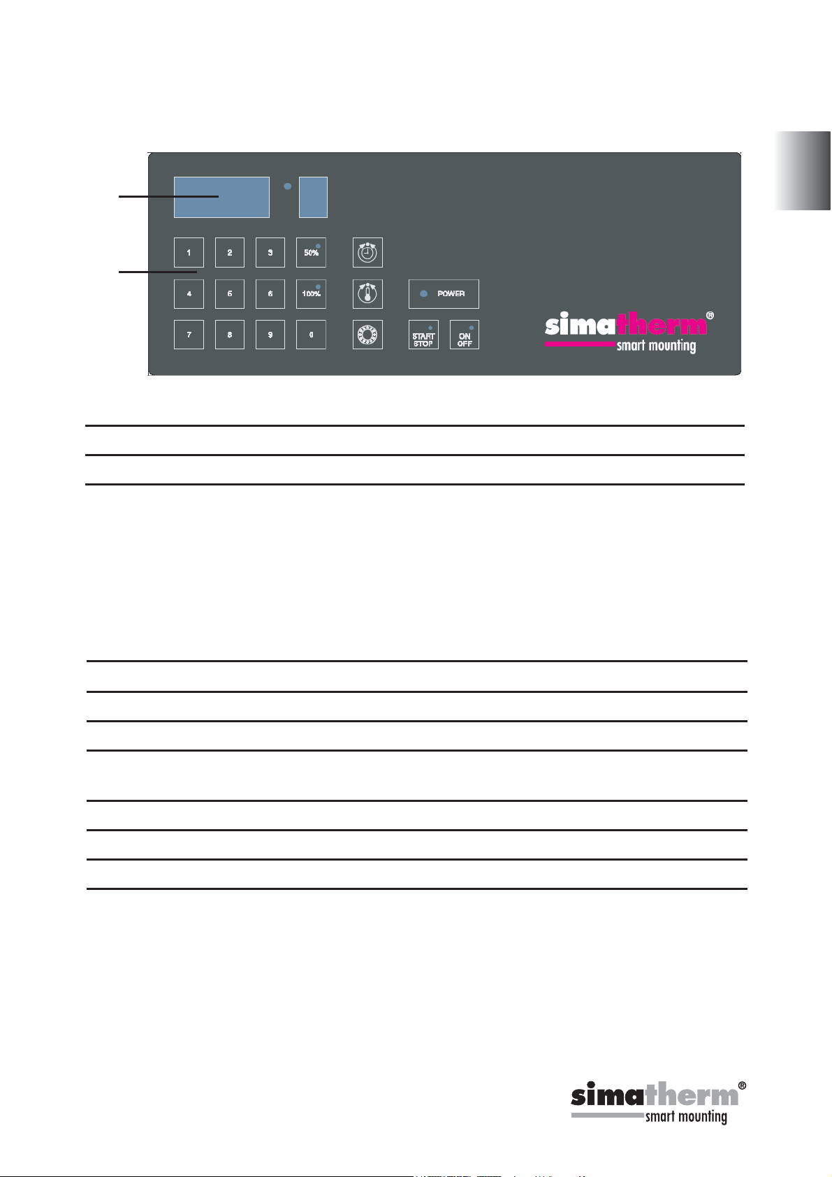
5.1 Function of displays
A
B
A) The main display shows the selected time or temperature for heating.
Display Indication
t time in minutes
°C temperature in degrees Celsius
°F temperature in degrees Fahrenheit
B) The power display shows the selected power setting.
5.2 Function of buttons
English
Button Function
POWER
TIME TIME MODE
TEMP TEMP MODE
BEARING BEARING MODE - recommended heating temperature for
START/STOP To start and stop heating.
ON/OFF Press to start or stop the heater.
50% Power reduced to 50%.
100% Full capacity.
control lamp for main switch on
bearings of 110°C (230°F) is automatically selected.
© simatec ag Induction Heater IH 240 23

5.3 Temp mode
• Select TIME MODE. The main display shows °C or °F in TEMP MODE.
• The selected temperature is shown on the main display. The default
temperature for bearings is 110 °C (230 °F).
If a different temperature is
desired, adjust the temperature on the main display.
• It may be desirable to heat bearings to temperatures above 110 °C
for increased mounting time. Consult the bearing specifications
to determine the maximum permitted temperature. Always ensure
the bearing doesn‘t lock due to an excessive expansion of the inner
ring compared to outer ring. See section 5.8.
• Spherical Roller Bearings (SRBs) are subjected to a special
heat treatment. These bearings can be operated at temperatures as
high as 200 °C. Heating these bearings above 110 °C will not cause
any damage as long as the bearing is still able to rotate. For other
bearings, a temperature of 125 °C must not be exceeded unless
otherwise specified.
Press the 50% key to reduce the POWER to 50%. Use the guidelines in
•
section 5.8 to determine the correct power setting.
• Press START/STOP to start the heater. The main display shows the
current temperature of the workpiece.
• When the selected temperature has been reached, the heater
demagnetises the workpiece, switches off, and generates an
acoustic signal for 10 seconds or until START/STOP is pressed.
• Press START/STOP to stop the heater.
• Remove the workpiece with proper handling equipment.
• If the workpiece remains on the heater, the heater will start again
when the temperature of the workpiece drops 10 °C (18 °F). Press
START/STOP to stop the heater and demagnetise the workpiece.
• The IH 240 is now ready to heat another workpiece with the
same settings.
© simatec ag Induction Heater IH 240 24

5.4 Time mode
• Select TIME MODE. The main display shows ‘t’ in TIME MODE.
•
Set desired heating time by adjusting on the main display.
• Press 50% to reduce the POWER to 50%. Use the guidelines in
section 5.8 to determine the correct power setting.
• Press START/STOP to start the heater. The main display shows the
time that remains.
• When the time has elapsed, the heater demagnetises the workpiece,
switches off, and generates an acoustic signal for 10 seconds.
• Press START/STOP to cancel the acoustic signal and stop the heater.
• Remove the workpiece with proper handling equipment.
• The IH 240 is now ready to heat another workpiece with the
same settings.
English
5.5 Temperature measurement
When the heater is not operating, the temperature of the workpiece can
be measured by pressing 0 and TEMP at the same time.
The LED on the START/STOP button flashes during temperature measurement. Press START/STOP to cancel temperature measurement.
5.6 Change of temperature unit
Press 0 and BEARING at the same time to switch between °C and °F.
The temperature unit setting remains the same even after disconnection
from mains power.
5.7 Demagnetisation
The workpiece is automatically demagnetised when heating is complete.
Demagnetisation will not occur if the power is interrupted or the main
switch is switched off. To use the IH 240 for demagnetisation only,
select TIME MODE and set the time to 0.1 minute (6 seconds).
© simatec ag Induction Heater IH 240 25

5.8 Power level selection
When heating bearings with an induction heater, most of the heat will be
generated in the inner bearing race. The heat will then be transferred
through the bearing. It is therefore important that bearings with small internal clearance or slight preload are heated slowly. Slow heating ensures that
the bearing expands evenly, thereby preventing damage to the bearing.
The shape, weight, size, and internal clearances all affect the amount of
time required to heat a bearing. The large variety of bearing types
precludes the possibility of providing a specific power level setting for
each type. Instead, the following guidelines are provided:
For sensitive bearings (including bearings with C1 or C2 internal
•
clearance) or bearings with brass cages and when using the small yoke,
reduce the power to 50%.
6 Safety features
The IH 240 is equipped with the following safety features:
• Main switch with overcurrent circuit breaker
• Automatic overheating protection
• Automatic current control
• In the TEMP MODE the heater will switch off if the temperature probe
does not register a temperature increase of 1° every 30 seconds.
To increase the interval to 60 seconds, press MODE and DOWN at
the same time.
© simatec ag Induction Heater IH 240 26

7 Troubleshooting
A system fault will be indicated by an acoustic signal and one of the following fault codes on the main display:
Display Fault Action
E00 E Electronic failure Return heater for repair
E01 E Electronic failure Return heater for repair
E02 E Electronic failure
E03 E Overheated coil Wait until the inductive coil cools
E04 E Selected time/temperature
out of range
E05 E Temperature increases
of less than 1° every 30
seconds (or 1° every 60
seconds)
E06 E Temperature probe not con-
nected (or defective)
E07 E Failure during current
measurement
Re-program
Check the temperature probe connection. If the connection is OK, select
the 60 second interval as described in
section 6 or operate the heater in TIME
MODE.
Check the temperature probe
Return heater for repair
English
8 Spare parts
IH 240-1 Printed circuit board
IH 240-2 Yoke 100 x 100 x 570 mm
IH 240-3 Yoke 65 x 65 x 570 mm
IH 240-5 Thyristor
IH 240-6 Thyristor protection board IH 240
IH 240-7 Main switch IH 240
IH 240-10 Set support yoke 100 x 100 x 150 mm
IH 240-11 Set support yoke 100 x 100 x 370 mm
IH P1 Temperature probe
© simatec ag Induction Heater IH 240 27

Nederland B.V.
Wagenmakerij 11
4762 AV Zevenbergen
T: 0168 371 538
F: 0168 338 329
E: info@beka.nl
I: www.beka.nl
www.simalube.nl
 Loading...