

Page 1
SCQ25
1
EN
DE
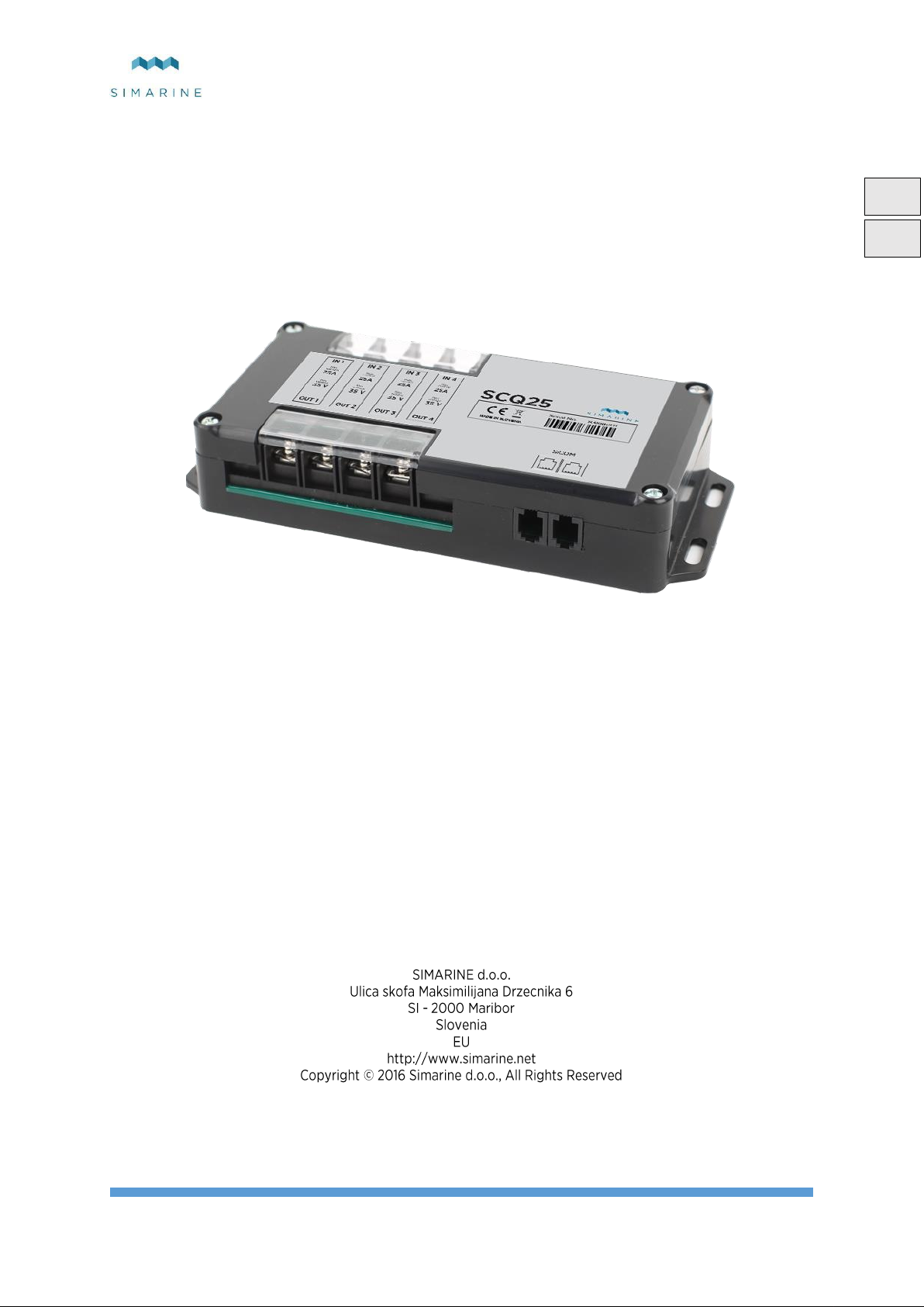
SIMARINE SCQ25
Quadro digital shunt module
USERS MANUAL
Revision 1.0
Page 2

SCQ25
2
Page 3

SCQ25
3
EN
Table of Contents
1 Introduction ...................................................................................................................................................................... 4
2 Safety ................................................................................................................................................................................ 4
3 Overview .......................................................................................................................................................................... 4
4 Installation ........................................................................................................................................................................ 4
4.1 Mounting ................................................................................................................................................................. 4
4.2 Cables ..................................................................................................................................................................... 4
4.2.1 SiCOM data cable .............................................................................................................................................. 4
4.3 Connecting .............................................................................................................................................................. 5
4.3.1 SCQ25 ................................................................................................................................................................ 5
5 Technical specifications .................................................................................................................................................... 6
6 Trouble shooting ............................................................................................................................................................... 6
6.1 Negative current values ........................................................................................................................................... 6
6.2 Shunt sensor is not visible on pico .......................................................................................................................... 6
7 Appendix .......................................................................................................................................................................... 7
Page 4
SCQ25
4
EN
Cable length
Cable type
< 5m
No limitations
>= 5m
2x2x0.25 mm2 Twisted pair (recommended)
1 Introduction
SCQ25 digital shunt module is Simarine’s most versatile module. It can be used to measure voltage, current.
SCQ25 has 4x 25 A integrated shunts capable of measuring voltage up to 35 V DC and continuous current up to 25 A on each
shunt.
2 Safety
Installation of Simarine electronics should be made by electrical specialists with proper safety equipment. When working with
batteries you should wear protective clothing and eye protection.
CAUTION: Batteries contain acid, a corrosive, colorless liquid that will burn your eyes, skin and clothing. Should the acid
come in contact with eyes, skin or clothing, wash it immediately with soap under fresh water for at least 15 minutes, and seek
medical support immediately.
CAUTION: Do NOT connect anything to a damaged battery. It could heat up, catch fire or explode.
CAUTION: Lead-acid Batteries can generate explosive gases during operation. Never smoke, allow flames or sparks near the
battery. Make sure to keep sufficient ventilation around the battery.
CAUTION: When working with a battery remove all personal metal items like watches, rings, necklaces and bracelets. Metal
items in contact with the battery terminals might cause a short circuit with a very high electric current, which may heat up and
melt nearby objects and cause severe burns.
3 Overview
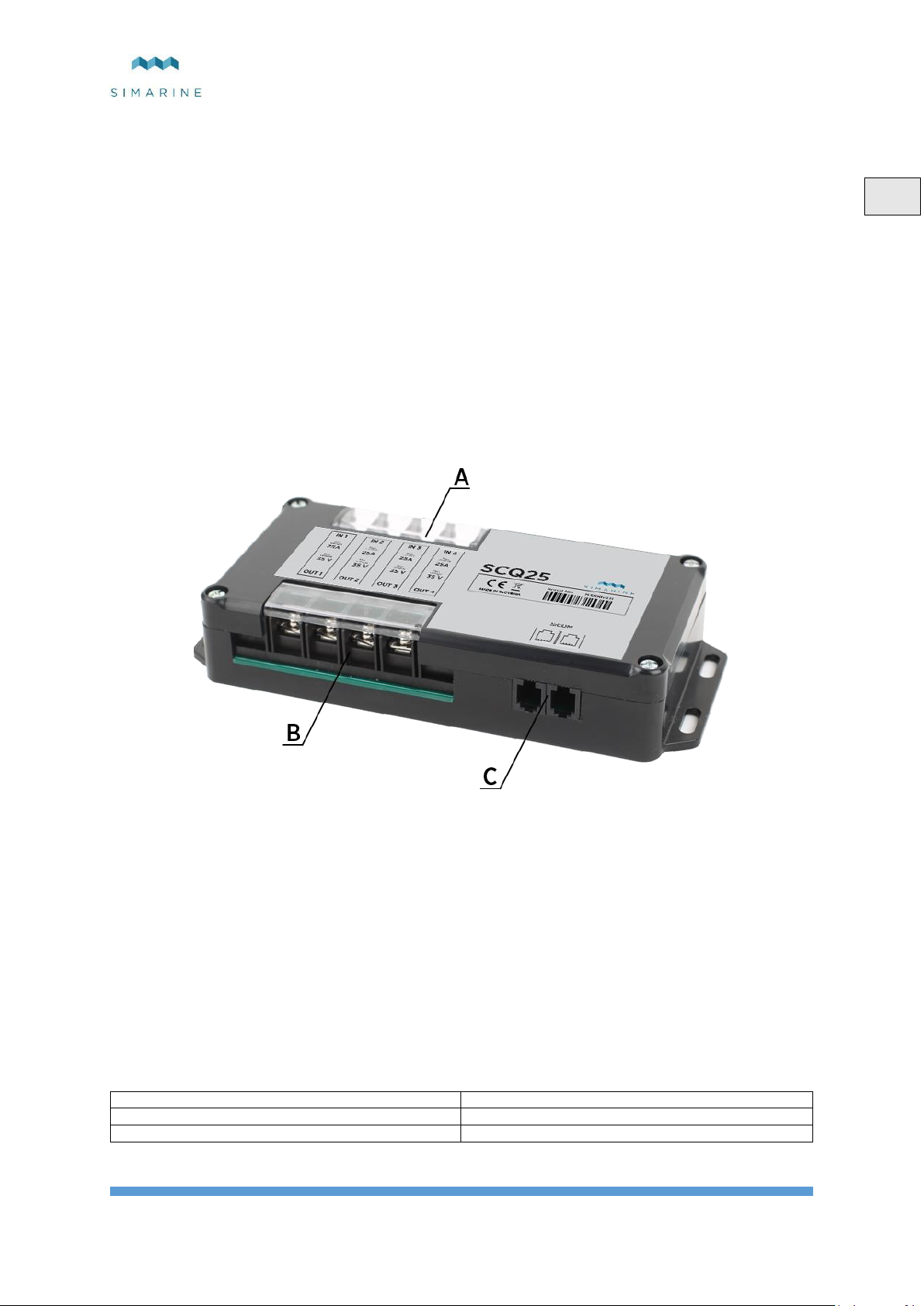
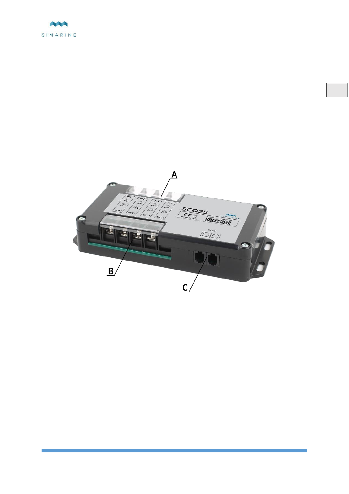
Picture 1 SCQ25
A – 4x shunt input
B – 4x shunt output
C – 2x SiCOM port
4 Installation
4.1 Mounting
CAUTION: install the shunt module in a clean dry place, protected from accidental spilling of liquids.
- You can fix the shunt module with the supplied screws using four holes on both sides of the module.
- Connect all cables (see section 4.3 Connecting).
4.2 Cables
4.2.1 SiCOM data cable
For the SiCOM connection use the supplied cable. If not possible, use the following table to determinate the right cable type.
Page 5
SCQ25
5
EN
4.3 Connecting
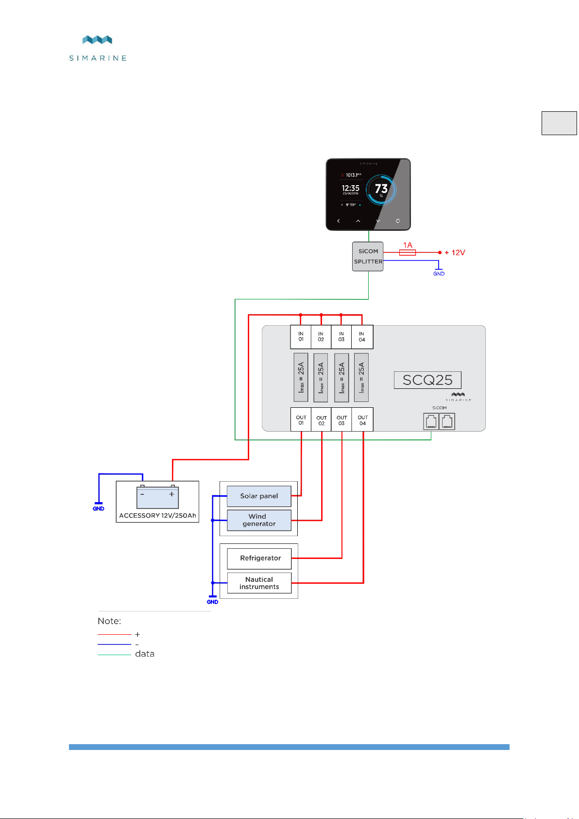
For proper function of Simarine SCQ25 digital shunt module it is necessary to:
1. Connect SCQ25 to Simarine PICO via the SICOM port.
2. Connect consumers/generators minus or plus terminal through one SCQ25 shunt. *
* Each correctly connected shunt needs to be configured. This is done via PICO in an easy way. The configuration process is
described in PICO’s manual.
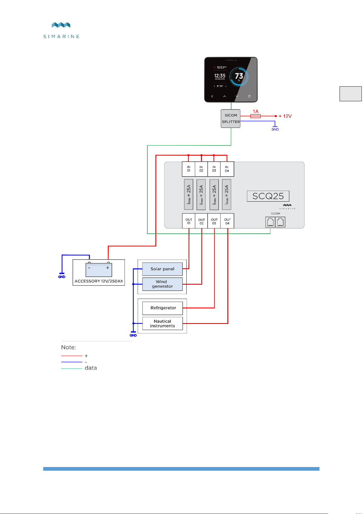
4.3.1 SCQ25
Picture 2SCQ25 (POS)
Page 6

SCQ25
6
EN
Operating
Voltage range
6 - 35 V
Temperature range
-20 – 70 °C (-4 – 158 °F)
Power consumption at 12V
Operating
2.5 mA
Current Measuring ( per channel )
Range
0.01 – 25 A
Accuracy
0.6 %
Resolution
0.01 A
Sampling rate
100 ms
Maximal current
Continuous
25 A
Peak current ( <1min )
35 A
Dimensions
183x91x34 mm
Connectivity
Up to
Shunt
4
SICOM port
2
5 Technical specifications
Table 1Technical specification
6 Trouble shooting
6.1 Negative current values
If PICO is showing wrong sign for current value. Check if the shunt is correctly installed. This means the consumers/generators
minus (optionally plus) terminal is connected to the IN terminal on the shunt. If this is not the case, you can reinstall the shunt
or simply switch the IN and OUT terminal via the shunt configuration on PICO.
6.2 Shunt sensor is not visible on pico
If the shunt sensor is not visible in PICO’s menu, check the following:
Is the SCQ25 properly connected via the SiCOM port to the PICO.
If you are using your own SiCOM cable make sure it has the right square and is twisted.
Page 7
SCQ25
7
EN
7 Appendix
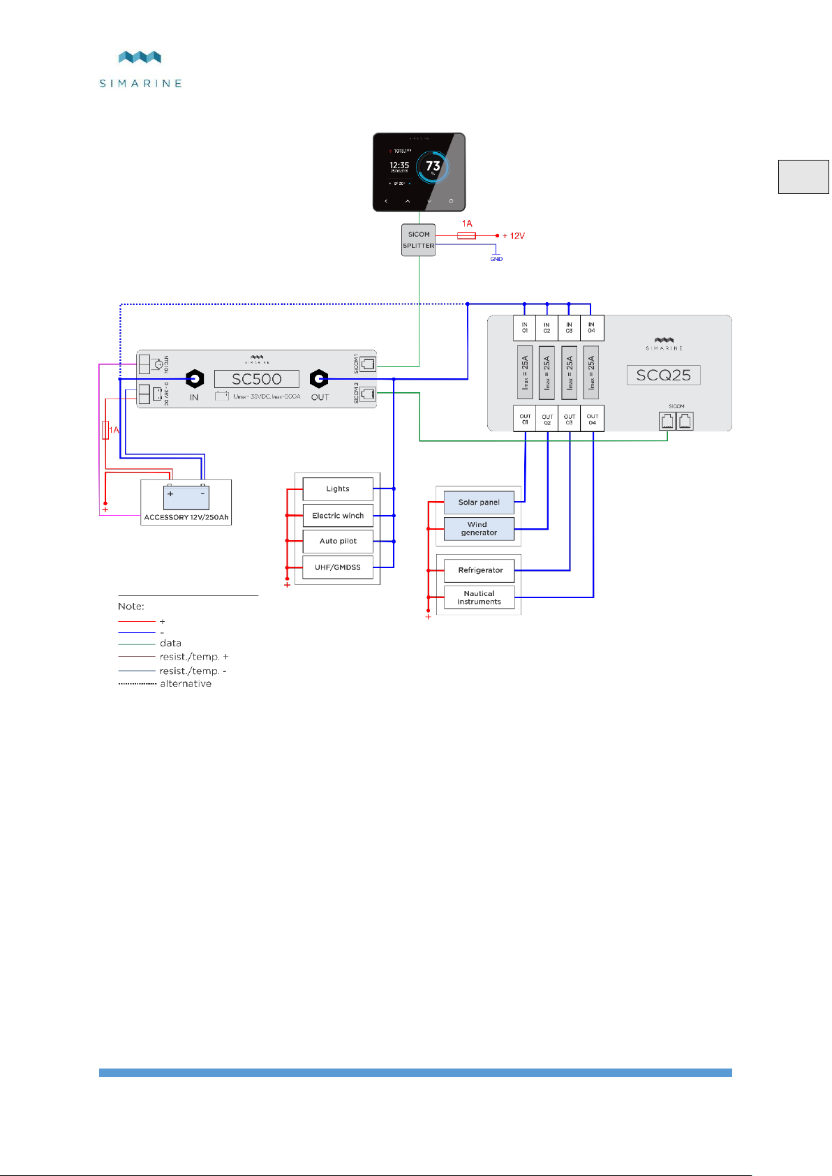
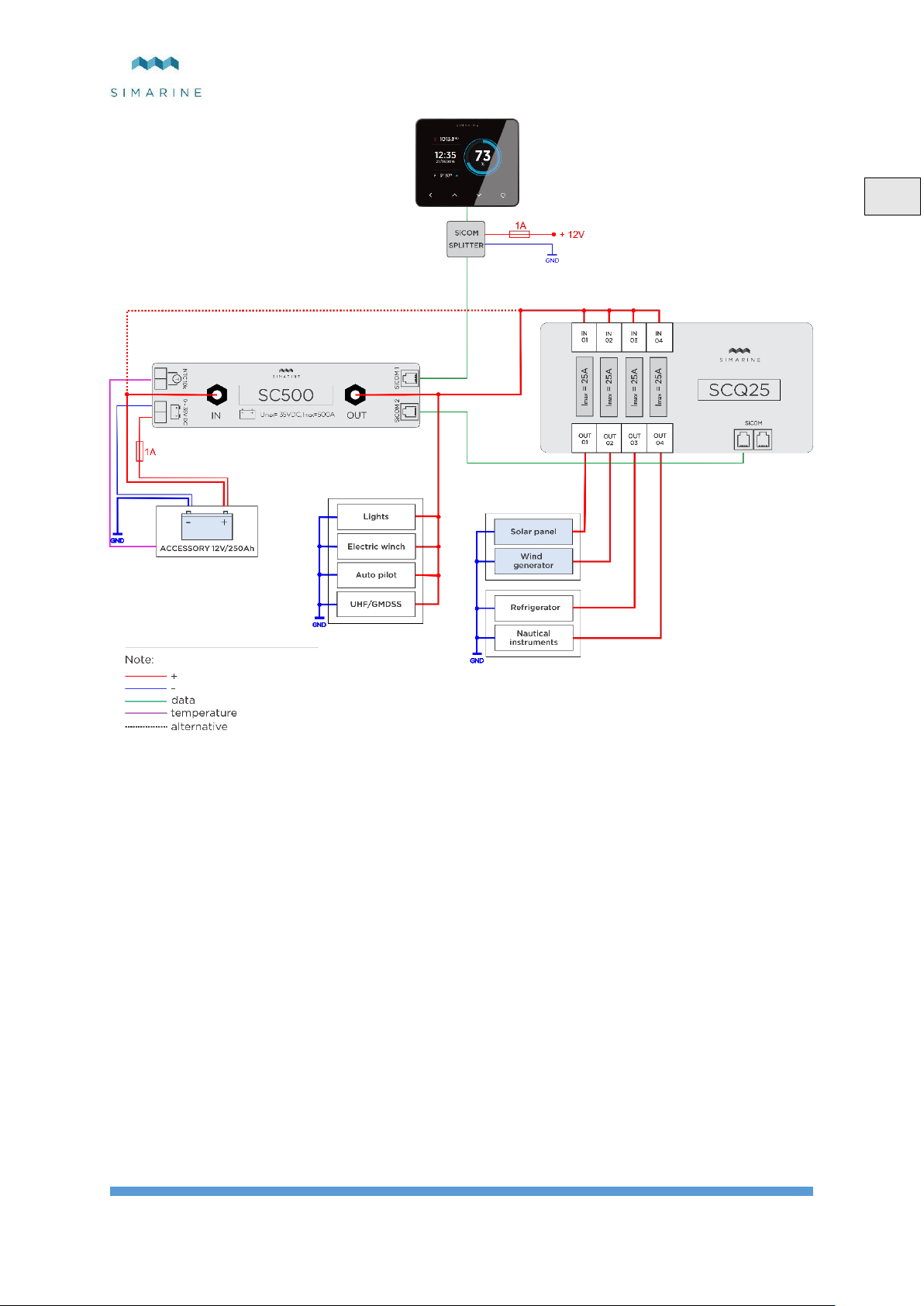
Picture 3SCQ25(NEG) and SC500(NEG)
Page 8
SCQ25
8
EN
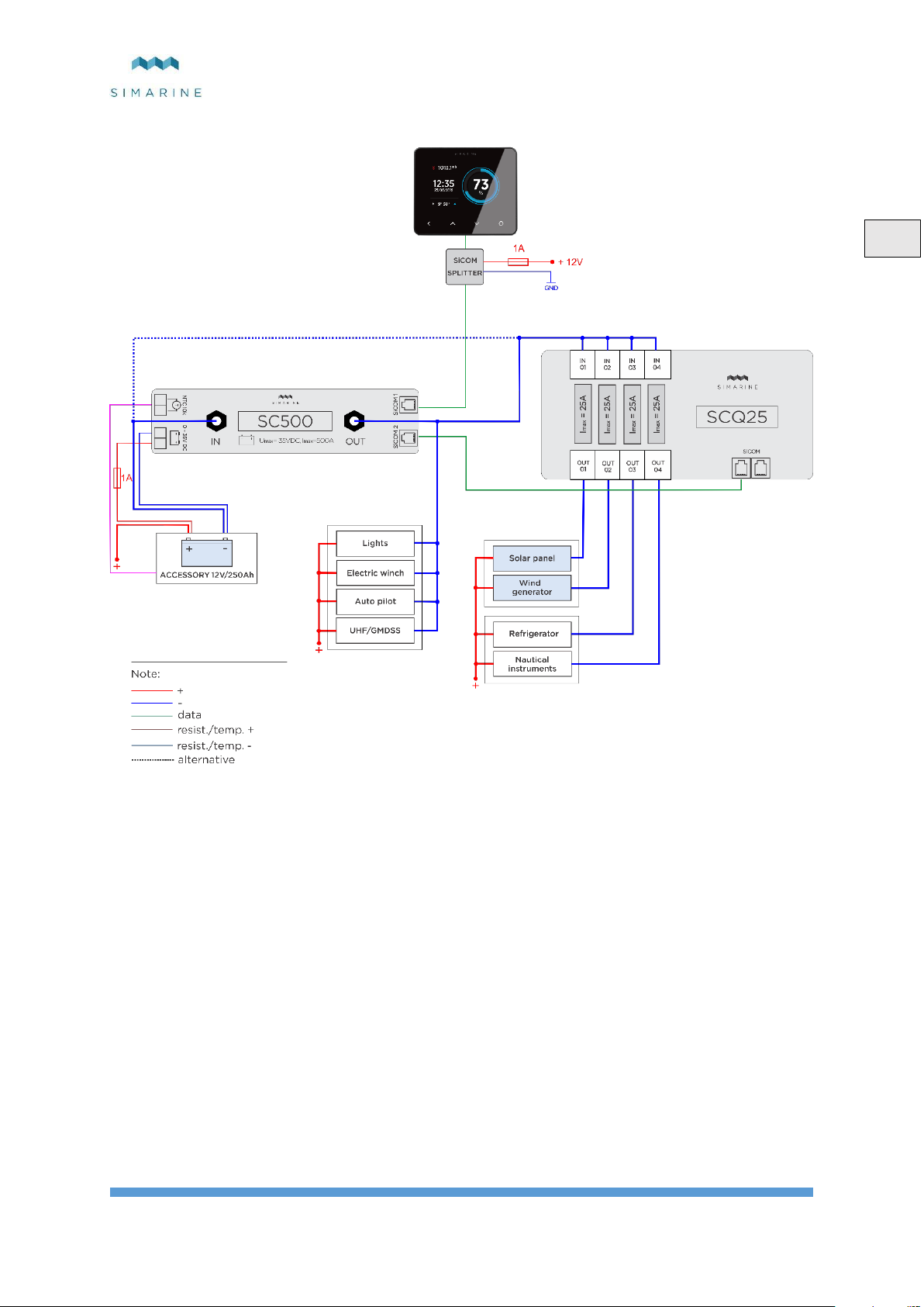
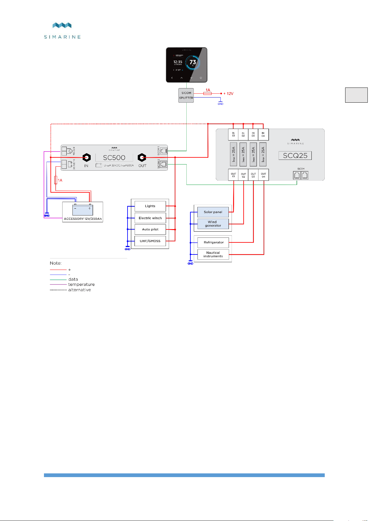
Picture 4SCQ25(POS) and SC500(POS)
Page 9

SCQ25
9
DE
Tabelleninhalt
1 Einleitung ....................................................................................................................................................................... 10
2 Sicherheit ........................................................................................................................................................................ 10
3 Überblick ........................................................................................................................................................................ 10
4 Einrichtung ..................................................................................................................................................................... 10
4.1 Befestigung ........................................................................................................................................................... 10
4.2 Verdrahtung .......................................................................................................................................................... 10
4.3 Verdrahtungsdiagramm ......................................................................................................................................... 11
5 Technische Einzelheiten ................................................................................................................................................. 12
6 Fehler Beseitigung .......................................................................................................................................................... 12
6.1 Negative stromwerte ............................................................................................................................................. 12
6.2 Shunt Sensor ist nicht sichtbar auf dem PICO ...................................................................................................... 12
7 Appendix ........................................................................................................................................................................ 13
Page 10
SCQ25
10
DE
1 Einleitung
SCQ25 digital Shunt Module ist Simarines vielseitigster Module. Er kann als Spannung und Strom Messgerate benutzt Verden.
SCQ25 hat je 4x25 A integrierten Shunt und ist in der Lage, Spannung und Dauerstrom bis zu 25 A auf jedem Shunt zu messen.
2 Sicherheit
Die Installation der Simarine-Elektronik sollte von Elektrofachkräften durchgeführt werden. Wenn Sie mit Batterien arbeiten,
sollten Sie Schutzkleidung und Augenschutz tragen.
VORSICHT: Die Batterien enthalten Säure, eine korrosive, farblose Flüssigkeit, die Augen, Haut und Kleidung verbrennen
wird. Falls Säure in Kontakt mit Augen, Haut oder Kleidung kommt, waschen Sie sie sofort mit Seife unter Süßwasser für
mindestens 15 Minuten und sofort medizinische Unterstützung suchen.
VORSICHT: Schließen Sie NICHTS an eine beschädigte Batterie an. Sie könnte aufheizen, Feuer fangen oder explodieren.
VORSICHT: Blei-Säure-Batterien können während des Betriebs explosive Gase erzeugen. Rauchen Sie niemals in der Nähe
der Batterie. Achten Sie darauf, dass eine ausreichende Belüftung um die Batterie gegeben ist.
VORSICHT: Beim Arbeiten mit einer Batterie alle persönlichen Metallgegenstände wie Uhren, Ringe, Halsketten und
Armbänder entfernen. Wenn Metallgegenstände die Batterieklemmen berühren, kann der daraus resultierende Kurzschluss
Gegenstände schmelzen und schwere Verbrennungen verursachen.
3 Überblick
Bild 1 SCQ25 Überblick
A - 4x Shunt Eingang
B - 4x Shunt Ausgang
C - 2x SiCOM-Anschluss
4 Einrichtung
4.1 Befestigung
VORSICHT: Installieren Sie den Shunt Module an einem sauberen, trockenen Ort, geschützt vor versehentlichem Verschütten
von Flüssigkeiten.
Sie können den Shunt Modul mit den mitgelieferten Schrauben mit fier Löchern auf beiden Seiten des Moduls
befestigen.
Schließen Sie alle Kabel an (siehe Abschnitt 4.2 Verdrahtung).
4.2 Verdrahtung
Für die ordnungsgemäße Funktion des Simarine SCQ25 Digital-Shunts sind Folgende Schritte notwendig:
Verbinden Sie SCQ25 über den SICOM-Anschluss mit Simarine PICO.
Verbinden Sie die Verbraucher/Generatoren mit einem der Vier SCQ25 Shunts.
Jeder korrekt angeschlossene Shunt muss konfiguriert werden. Dies geschieht über den PICO auf eine einfache Weise. Die
Konfiguration ist im PICO Handbuch beschrieben.
Page 11
SCQ25
11
DE
4.3 Verdrahtungsdiagramm
Bild 2SCQ25 angeschlossen an den Plus pol
Page 12

SCQ25
12
DE
In Betrieb
Spannungsbereich
6 - 35 V
Temperaturbereich
-20 - +70 °C
Stromverbrauch bei 12V
In Betrieb
2,5 mA
Strom Messung ( Pro Kanal )
Bereich
0,01 – 25 A
Genauigkeit
0,6 %
Auflösung
0,01 A
Abtastgeschwindigkeit
100 ms
Maximal Strom
Durchgehend
25 A
Stromspitze ( <1min )
35 A
Dimensionen
183x91x34 mm
Anschlussmöglichkeiten
Bis zu
Shunt
4
SICOM Anschluss
2
5 Technische Einzelheiten
Tabelle 1Technische Einzelheiten
6 Fehler Beseitigung
6.1 Negative stromwerte
Wenn PICO das falsche Zeichen für den aktuellen Strom Wert anzeigt. Überprüfen Sie, ob der Shunt richtig installiert ist. Das
bedeutet, dass der Minus (optional Plus) terminal des Verbrauchers/Generator mit dem IN-Anschluss des Shunts verbunden
ist. Wenn dies nicht der Fall ist, können Sie den Shunt neu installieren oder einfach den IN und OUT Anschluss über die Shunt
Konfiguration auf dem PICO umschalten.
6.2 Shunt Sensor ist nicht sichtbar auf dem PICO
Ist kein Shunt / Tank Sensor sichtbar auf dem PICO, überprüfen Sie Folgendes:
Ist der SCQ25 ordnungsgemäß über den SICOM-Anschluss mit dem PICO verbunden.
Wenn Sie Ihr eigenes Kabel für den SICOM Daten Transfer benutzen, Stelen sie sicher, dass sie den Richtigen Kabel
typ benutzen.
Page 13
SCQ25
13
DE
7 Appendix
Bild 3SCQ25(NEG) und SC500(NEG)
Page 14
SCQ25
14
DE
Bild 4SCQ25(POS) und SC500(POS)
 Loading...