

SIMARINE PICO, PICOone User Manuals
EN
PICO and PICOone
Battery and Tank Monitoring System
USER MANUALS
Revision 1.3
SIMARINE d.o.o. | Ulica skofa Maksimilijana Drzecnika 6 | SI - 2000 Maribor | Slovenia | EU
www.simarine.net | Copyright © 2017 SIMARINE d.o.o. | All Rights Reserved.

PICO
2
EN
Table of contents
1 Introduction ...................................................................................................... 6
2 Accessories ...................................................................................................... 6
3 Safety ............................................................................................................... 6
4 Declaration of conformity ................................................................................ 7
5 Installation ....................................................................................................... 7
5.1 PICO mounting ....................................................................................... 7
5.2 PICO standalone ..................................................................................... 8
5.3 PICO panel-mount .................................................................................. 9
5.4 Connecting ............................................................................................ 11
5.4.1 Power cable ....................................................................................... 11
5.4.2 SiCOM data cable ............................................................................. 11
5.4.3 How to connect a SC300/SC302T/SC500 Shunt .............................. 12
5.4.4 How to connect a SCQ25 Quadro Digital Shunt module ................. 12
5.4.5 How to connect a Shunt SCQ25T Quadro Digital Shunt ant Tank
module 12
5.4.6 How to connect a ST107 Tank module ............................................. 12
6 Basic setup ..................................................................................................... 13
6.1 Start screen after first connection .......................................................... 14
6.2 Language settings .................................................................................. 14
6.3 Units ...................................................................................................... 14
6.4 Battery configuration ............................................................................ 15
6.4.1 Add new battery ................................................................................ 15
6.5 Tank configuration ................................................................................ 16
6.5.1 Add new Tank................................................................................... 16
7 Displaying battery, tank, temperature and air pressure measurements .......... 17
7.1 BATTERIES SCREEN ......................................................................... 18

PICO
3
EN
7.2 TANKS SCREEN ................................................................................. 18
7.3 TEMPERATURES SCREEN ............................................................... 19
7.4 BAROGRAPH SCREEN ...................................................................... 19
8 Device configuration ...................................................................................... 20
8.1 GENERAL SETTINGS ........................................................................ 20
8.1.1 SCREEN ........................................................................................... 20
8.1.1.1 AUTO BRIGHTNESS ............................................................. 20
8.1.1.2 BACKLIGHT .......................................................................... 20
8.1.1.3 MIN. BRIGHTNESS ............................................................... 20
8.1.2 DEVICE............................................................................................ 21
8.1.2.1 AUTO STANDBY ................................................................... 21
8.1.2.2 STANDBY AFTER ................................................................. 21
8.1.2.3 SLEEP SCREEN ..................................................................... 21
8.1.3 LANGUAGE .................................................................................... 22
8.1.4 UNITS .............................................................................................. 22
8.2 DATA MANAGEMENT ...................................................................... 22
8.3 DEVICES .............................................................................................. 22
8.3.1 BATTERIES ..................................................................................... 23
8.3.1.1 NAME ...................................................................................... 23
8.3.1.2 TYPE ....................................................................................... 23
8.3.1.3 CAPACITY ............................................................................. 23
8.3.1.4 VOLTMETER ......................................................................... 23
8.3.1.5 AMMETERS ........................................................................... 24
8.3.1.6 TEMPERATURE SENSORS .................................................. 24
8.3.2 TANKS ............................................................................................. 24
8.3.2.1 NAME ...................................................................................... 24
8.3.2.2 TYPE ....................................................................................... 24
8.3.2.3 SENSOR TYPE ....................................................................... 25

PICO
4
EN
8.3.2.4 SENSOR .................................................................................. 25
8.3.2.5 CAPACITY ............................................................................. 25
8.3.2.6 CALIBRATION POINTS ........................................................ 25
8.3.2.7 DISPLAY PRIORITY ............................................................. 25
8.3.2.8 DELETE .................................................................................. 26
8.3.3 TEMPERATURE SENSORS ........................................................... 26
8.3.3.1 NAME ...................................................................................... 26
8.3.3.2 TYPE ....................................................................................... 26
8.3.3.3 DEVICE ................................................................................... 27
8.3.3.4 DISPLAY PRIORITY ............................................................. 27
8.3.3.5 RANGE MIN ........................................................................... 27
8.3.3.6 RANGE MAX ......................................................................... 27
8.3.3.7 CALIBRATION ...................................................................... 27
8.3.3.8 DELETE .................................................................................. 27
8.3.4 CURRENT SENSORS ..................................................................... 28
8.3.4.1 NAME ...................................................................................... 28
8.3.4.2 RANGE .................................................................................... 28
8.3.4.3 REVERSE CURRENT ............................................................ 28
8.3.4.4 ADD CURRENT ..................................................................... 28
8.3.4.5 BATTERY ............................................................................... 29
8.3.4.6 DISPLAY PRIORITY ............................................................. 29
8.3.5 VOLTMETERS ................................................................................ 30
8.3.6 OHMMETERS ................................................................................. 30
8.3.7 COULOMB COUNTER................................................................... 30
8.4 WI-FI..................................................................................................... 31
8.4.1 OPERATION .................................................................................... 31
8.4.2 AUTO OFF ....................................................................................... 31
8.4.3 MODE .............................................................................................. 31

PICO
5
EN
8.4.4 SSID ................................................................................................. 31
8.4.5 TCP IP .............................................................................................. 32
8.4.6 TCP PORT ........................................................................................ 32
8.4.7 UDP IP .............................................................................................. 32
8.4.8 UDP PORT ....................................................................................... 32
8.4.9 PASSWORD .................................................................................... 32
8.4.10 WI-FI RESET ............................................................................... 32
8.5 DATE & TIME ..................................................................................... 32
8.5.1 TIME ................................................................................................ 33
8.5.2 DATE................................................................................................ 33
8.5.3 TIME ZONE ..................................................................................... 33
8.5.4 TIME FORMAT ............................................................................... 33
8.5.5 DATE FORMAT .............................................................................. 33
8.6 BAROGRAPH ...................................................................................... 33
8.6.1 ALTITUDE ...................................................................................... 33
8.6.2 TIME INTERVAL ............................................................................ 33
8.7 SYSTEM ............................................................................................... 33
8.7.1 COMMUNICATION DEVICES ...................................................... 33
8.7.2 SYSTEM INFO ................................................................................ 34
8.7.3 SYSTEM RESET ............................................................................. 34
9 Mobile App .................................................................................................... 34
10 Firmware Upgrade ......................................................................................... 35
11 Technical Specifications ................................................................................ 36

PICO
6
EN
1 Introduction
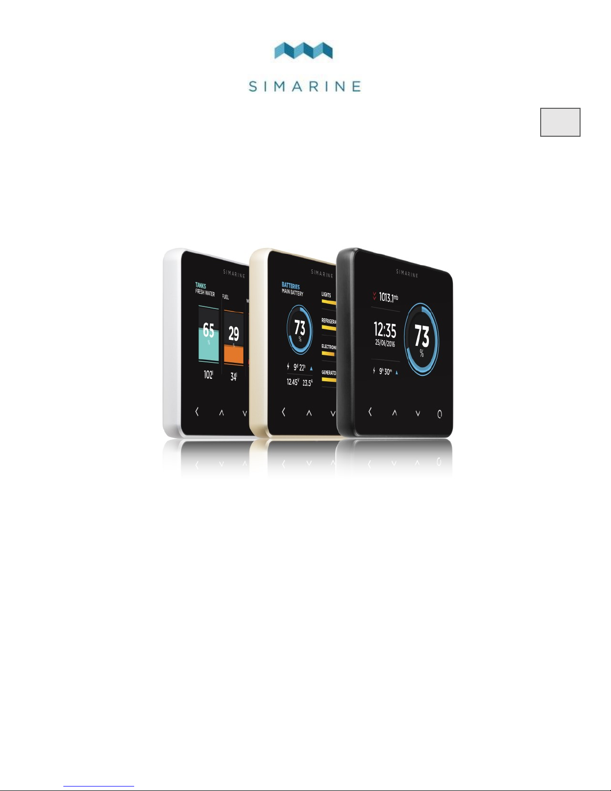
Congratulations on your purchase of the Simarine PICO Battery Monitor. Simarine
developed a state of the art DC Battery monitor.
Simarine’s PICO is a water and dust resistant device used to monitor DC power
sources as batteries and solar panels. The information is displayed on a large 3,5”
high resolution IPS display with Gorilla Glass and anti-reflective coating to ensure
superior visibility.
PICO is capable of monitoring up to 6 batteries, 14 tanks, 14 temperatures and 20
independent current sensors (Shunts).
PICOone is capable of monitoring up to 2 batteries, 2 tanks, 2 temperatures and 20
independent current sensors (Shunts).
PICO and PICOone are equipped with a Wi-Fi module to communicate with the
PICO application available for Android and iPhone smartphones. The application
allows accessing live data, analyzing history data, configuring PICO and perform a
firmware upgrade of PICO.
2 Accessories
SC300 Digital Shunt – SIMARINE High Precision 300A Shunt
SC500 Digital Shunt – SIMARINE High Precision 500A Shunt
SC302T Digital Shunt – SIMARINE High Precision 300A Shunt with 2
resistance inputs for tank level measurement and 2 voltage inputs for measuring
voltages of two batteries.
SCQ25 Quadro Digital Shunt Module – SIMARINE High Precision 4x25A
Shunt
SCQ25T Quadro Digital Shunt and Tank Module – SIMARINE High Precision
4x25A Shunt and Tank Interface Module with 4 resistance and 3 voltage inputs.
ST107 Digital tank interface module with 4 resistance and 3 voltage Inputs
3 Safety
Installation of Simarine electronics should be made by electrical specialists with
proper safety equipment. When working with batteries you should wear protective
clothing and eye protection.

PICO
7
EN
CAUTION: Batteries contain acid, a corrosive, colorless liquid that will burn your
eyes, skin and clothing. Should the acid come in contact with eyes, skin or
clothing, wash it immediately with soap under fresh water for at least 15 minutes,
and seek medical support immediately.
CAUTION: Do NOT connect anything to a damaged battery. It could heat up,
catch fire or explode.
CAUTION: Lead-acid batteries can generate explosive gases during operation.
Never smoke, allow flames or sparks near the battery. Make sure to keep sufficient
ventilation around the battery.
CAUTION: When working with a battery, remove all personal metal items like
watches, rings, necklaces and bracelets. Metal items in contact with the battery
terminals might cause a short circuit with a very high electric current, which may
heat up and melt nearby objects and cause severe burns.
4 Declaration of conformity
MANUFACTURER:
SIMARINE d.o.o.
ADDRESS:
Ulica skofa Maksimilijana
Drzecnika 6,
SI-2000 Maribor, Slovenia, EU
Declares that the following product:
PRODUCT TYPE:
PICO
Conforms to the requirements of the following Directives of the European Union:
EMC Directive 2014/30EU, RoHS Directive 2002/95/EC
The above product is in conformity with the following harmonized standards:
EN61000-6-3: 2001 EMC - Generic Emissions Standard, EN61000-6-2: 2005
EMC - Generic Immunity Standard
5 Installation
5.1 PICO mounting
SIMARINE PICO should be installed in a visible place to provide good
readability. Please note that ONLY the PICO/PICOone display unit is water
and dust resistant! Any other modules including splitter should not be exposed to
PICO
8
EN
high humidity or liquids in any case. The mounting process and installation cutouts
depend on the model, as described in following sections.
5.2 PICO standalone
PICO Standalone version has dimensions of 98 x 84 x 10mm and needs NO
installation cutout. The mounting process requires drilling of 5 (PICOone) or 6
(PICO) mounting holes and access to the rear of the mounting surface. In case you
have NO rear access, you can bond it using supplied double sided tape.
Step to be taken for proper mounting:
1. Before the drilling, check if there is enough space to mount your PICO.
2. Mark mounting holes using the supplied installation template.
3. Drill all holes.
4. Connect the connector on the back side of PICO to the splitter cable (be
sure to align the pins correctly) and fasten it by turning the safety ring
clockwise.
5. Finish mounting PICO from the back side with the supplied threaded rod
and nuts. Screws, rods and nuts MUST be fastened by hand. Excessive
force may damage the threads on PICO.
97,50
8
3
,
0
0
77,30
77,30
6
2
,
8
0
6
2
,
8
0
1
1
,
4
0
10,00
11,00
38,6538,65
1
,
2
5
1
0
,
1
0
10,10
Unit: mm
1
8
,
5
0
Waterproof air pressure vent
WARRANTY VOID IF SEAL BROKEN!
PICO
9
EN
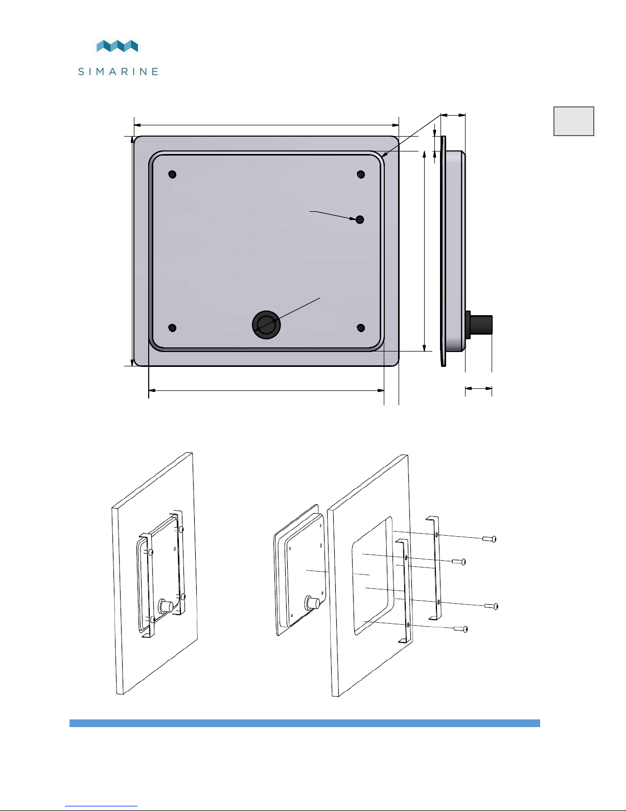
5.3 PICO panel-mount
PICO Panel-mount version dimensions are 108.5 x 94 x 10mm. It needs an
installation cutout of 98 x 83mm. It can be mounted with supplied threaded rods
and brackets or bonded with adhesive if there is no rear access to the mounting
surface.
Steps to be taken for proper mounting:
1. Before cutting out, check if there is enough space for your PICO.
2. Mark the cutout line with the supplied installation template.
3. Using a saw, carefully cut out the marked area.
4. Connect the connector on the back side of PICO to the splitter cable (be
sure to align the pins correctly) and fasten it by turning the safety ring
clockwise.
5. Finish mounting PICO from the back side with the supplied threaded rod
and nuts. Screws, rods and nuts MUST be fastened by hand. Excessive
force may damage the threads on PICO.
PICO
10
EN
108,50
9
4
,
0
0
R
6
,
0
0
96,50
8
2
,
0
0
11,00
10,00
6
,
0
0
6,00
Unit: mm
1
1
,
4
0
Waterproof air pressure vent
WARRANTY VOID IF SEAL BROKEN!

PICO
11
EN
5.4 Connecting
5.4.1 Power cable
Minimum power cable cross-section requirement at maximal temperature of
insulation: 70 °C (160 °F).
Continuous current
Cable cross-
sectional area
500 A
220 mm2
400 A
150 mm2
300 A
95 mm2
200 A
50 mm2
100 A
25 mm2
CAUTION: Failure to observe the required cable cross-sections can damage the
shunt, wiring, or cause fire.
5.4.2 SiCOM data cable
For the SiCOM connection use the supplied cable. If not possible, use the
following table to determinate the right cable type.
Cable length
Cable type
< 5m
No limitations
>= 5m
2x2x0.25 mm2 Twisted pair
(recommended)
Pico is connected to the SiCOM bus via attached Splitter, which is an entry point
for other devices and for the power connection. Splitter must be connected to the
power (6-35V) with red/black cable. It is recommended that the power cable is
connected behind the main switch, so you can power off the complete system,
although the total power consumption of the system is very low (usually <100mA
at normal operation).

PICO
12
EN
5.4.3 How to connect a SC300/SC302T/SC500 Shunt
You can find the latest SC300/SC500 Digital shunt manual on this link (or visit our
website: https://www.simarine.net).
5.4.4 How to connect a SCQ25 Quadro Digital Shunt module
You can find the latest SCQ25 QUADRO DIGITAL SHUNT MODULE on this
link (or visit our website: https://www.simarine.net).
5.4.5 How to connect a Shunt SCQ25T Quadro Digital Shunt ant
Tank module
You can find the latest SCQ25 QUADRO DIGITAL SHUNT AND TANK
MODULE manual on this link (or visit our website: https://www.simarine.net).
5.4.6 How to connect a ST107 Tank module
You can find the latest ST107 TANK MODULE manual on this link (or visit our
website: https://www.simarine.net).
PICO
13
EN
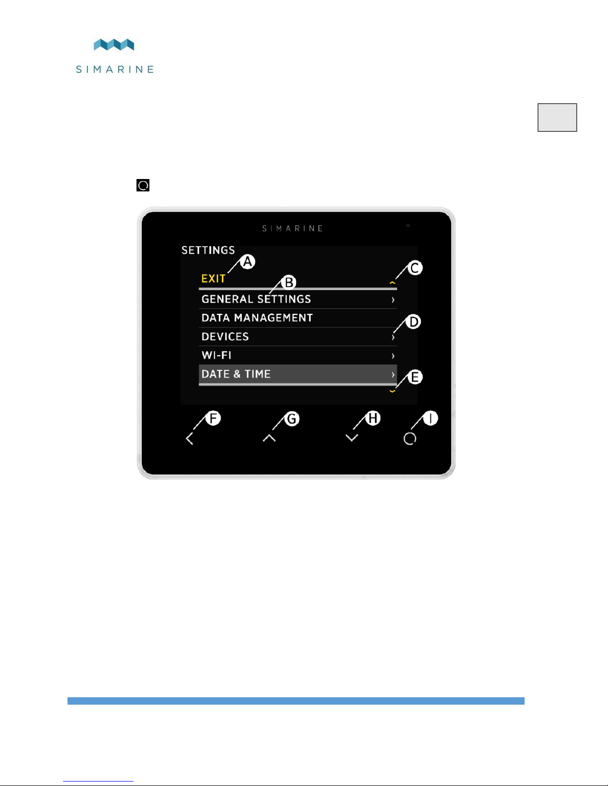
6 Basic setup
PICO’s menu management is transparent and easy to use. All changes can be done
using four touch buttons below the screen. Menus and settings on the picture below
can differ from the menus and settings on your device, since future firmware
upgrades might cause some minor changes in the menus and settings.
Long press button to enter the settings menu.
A – Label indicates current position in the menu
B – Currently selected item
C – Arrow indicates there is at least one more menu item in arrow direction
D – Arrow indicates there is a sub menu
E – Arrow indicates there is at least one more menu item in arrow direction
F – BACK BUTTON, is used to navigate one level back or leave the settings
menu.
G – UP BUTTON is used to navigate up in the menu, or changing value or
switching screens in live view.
H – DOWN BUTTON is used to navigate down in the menu, or changing value or
switching screens in live view.
I – ENTER BUTTON, long press activates settings, short press commits changes
or enters selected submenu.
 Loading...