

Page 1

3
ENGLISH
ÍNDICE
1. GENERA L INF OR MATION ................................................................................. 4
2. GENERAL DESCRIPTION OF THE MACHINE ................................................. 4
3. PARTS OF THE MACHINE. ........................................................................... 5
4. TRANSPORT ............................................................................................... 6
5. PICTOGRAMS. ............................................................................................ 6
6. SUPPLIED WITH MACHINE. ........................................................................ 7
6.1 ASSEMBLY ACCESORIES. .................................................................................................. 7
6.2 PARTS OF THE BENDING PLATE.
........................................................................................ 8
6.3 INVERSION PIN TO CONTROL THE BENDING ANGLE.
............................................................ 9
7. GETTING STARTE D ................................................................................... 10
7.1 CONNECTING TO THE SUPPLY ......................................................................................... 10
7.2 CONNECTING TO ELECTRICITY SOUR CE.
........................................................................... 11
7.3 CIRCUIT DIAGRAMS
....................................................................................................... 12
7.4 CHANGING PHASES TO ESTABLISH CORRECT BENDING DIRECTION.
................................... 15
8. MAKING A BEND ....................................................................................... 16
9. MAINTENANCE. ........................................................................................ 18
10. TROUBLE SHOOTING .............................................................................. 19
11. DATA SHEET ........................................................................................... 19
12. BENDING CAPACITY. .............................................................................. 19
13. SAFETY RECOMMEND ATIONS ................................................................. 20
14. WARRANTY ............................................................................................ 21
15. SPARE PARTS ......................................................................................... 21
16. ENVIRONMENT PROTECTION ................................................................. 21
17. DECALARATIONS ON NOISE ................................................................... 21
18. DECLARATIONS ON MECHANIAL VIBRATIONS ....................................... 21
Page 2

4
ENGLISH
1. GENERAL INFORMATION
WARNING: Please read and understand perfectly the present instruction before using the machine.
SIMA S.A. thanks you for your trust in our products and for purchasing the B ENDIN G OR COMBINED
ELECTRICAL CUTTING/BENDING MACHINE.
This manual provides you with the necessary instructions to start, use, maintain and in your case, repair of
the present machine. All aspects as far as the safety and health of the users is concerned have been stated.
Respecting all instructions and recomme ndations guarantees safety and low maintenance.
As such, reading this manual carefully is compulsor y for any person responsible for the use, maintenance or repair of
this machine.
It is recommended to have always this manual in an easily accessible place where the machine is being
2. GENERAL DESCRIPTION OF THE MACHINE
• The STAR 20 bending machines have been manufactured to bend flat and reinforced steel bars used for
construction and passive steel armatures for str uc tural concrete. The bending operation is done in cold using
mandrels to guarantee the bending interior diame te r is confor ming to the Euro p e a n norms.
• The combined machines bending/cutting models COMBI are des igned to bend as well as cut steel bars. The
cutting tools are two blades, one fixed and one moving. The cutting op e ration is done manually by pushing
the bar on the roller, dropping the bar into the cutting throat, low er ing the pro te c tio n guard and pres s ing the
pedal.
Any other use of this machine is considered inadequate and can be dangerous. Thus, this is completely
prohibited.
• The gear box is the main element of the machine . It is r espons i b le for tr ans m itting the needed energy to carry
out the steel bars bending.
• The machine is operated by an electrical motor that passes the movem e nt, by a transmis s ion to the bending
mechanism in which the different mandrills are mo unte d .
• The bending plate can be selected to work in two differe nt direc tio ns , lef t or right, by changing the direction of
rotation in the electrical control p ane l.
• The bending angle can be decided by inserting the pivot in the be nding plate . For a more prec is e bendi ng , the
ruler can be accurately adjusted by its handle.
• The commands panel is endowed with polyester, electrica l knobs eas ily id e ntified by pictograms.
• The machine is equipped with shutdown and backward moveme nt butto ns to facili tate its manoe uv re . The
emergency knobs on both sides of the machine can be used in case of danger or incor r ect m ano e uvres.
• The general bars bending manoeuvre is performed in low-voltag e (24V ) accor ding to the European standards.
• The original equipment (bolts, mandrels bend ing square) are heat-treated to withstand the tough type of work
the machine performs.
• The machine is furnished with a pedal to confirm and execute the manoeuvre, thus avo iding the upp er par ts to
be trapped while the machine is running.
• The work area is protected by a safety guard to limit possible accidents. This guard is transparent to allow
observation of the material being bent, avoiding getting to the upper p arts of the bend i ng ar e a.
• The machine is painted in oven with a highly resistance, anti-corrosion epoxy polyester paint.
• The original, electrical equipment is in confo rmi ty with the EC saf e ty nor ms.
Any use of the machine for applications other than those stated above is dangerous and therefore
strictly prohibited.
Page 3
5
ENGLISH
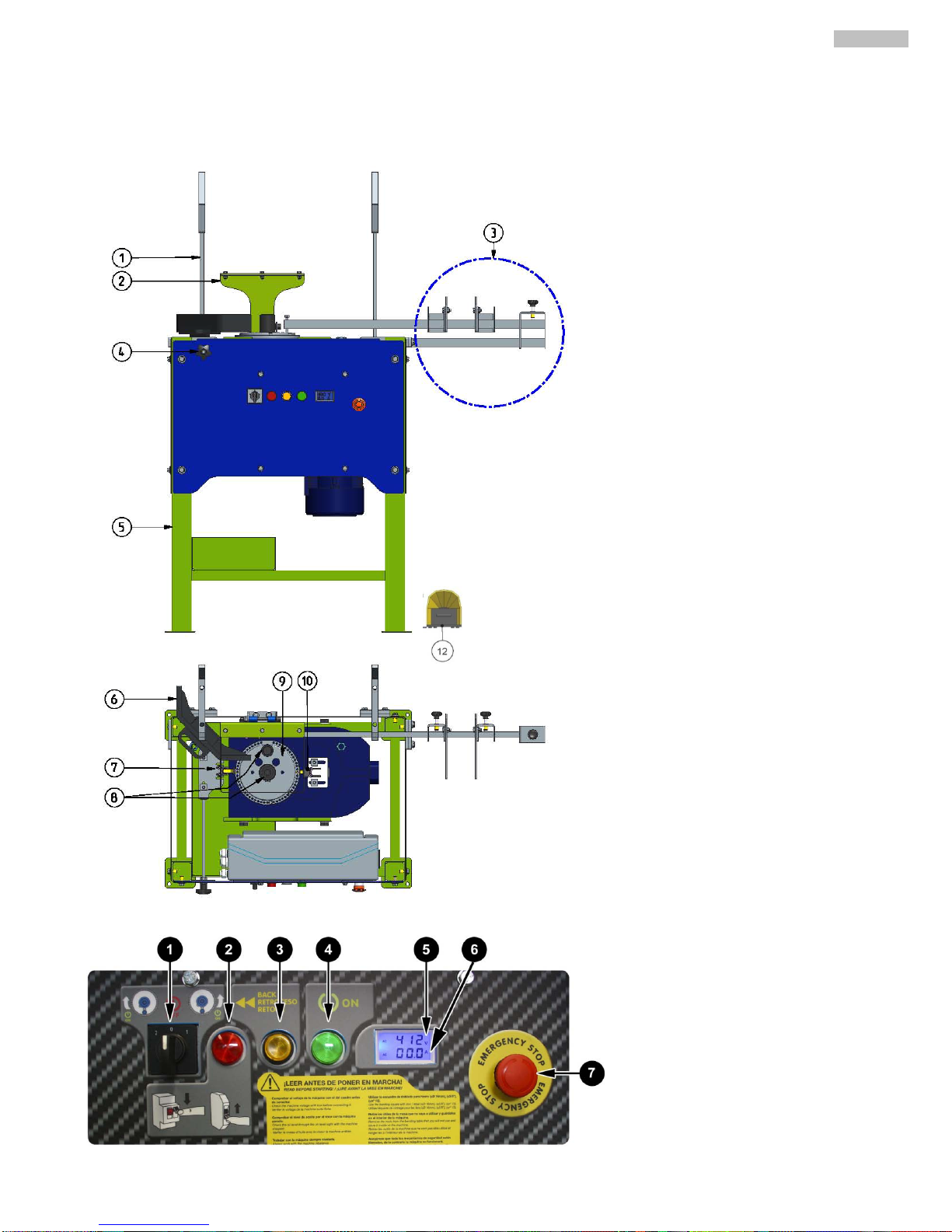
3. PARTS OF THE MACHINE.
1.
BENDING DIRECTION INVERTER
SWITCH.
2. OVERLOAD LIGH T.
3. FORCE RETURN SWITCH.
4. ON LIG HT
5. VOLTOMETER.
6. AMPERE METER.
7. EMERGENCY STOP BUTTON.
1. BAR SUPPORT.
2. BENDING BLADE PROTECTION.
3. BAR LENGTH MEASURER.
4. PRECISION ANGLE ADJUST.
5. CHASIS.
6. BENDING SUPPORT.
7. END OF BEND SENSOR.
8. BENDING MANDRELS.
9. BENDING PLATE.
10. END OF BEND SENSOR.
11.
Page 4
6
ENGLISH
4. TRANSPORT
The machine has been packed on a pallet that ma kes its trans port with trucks or manual pallets trans porters
easy. Its weight and other dimensions (See the table of technical characteristics on the present manual) make it
possible to transport the machine in light vehicl e s .
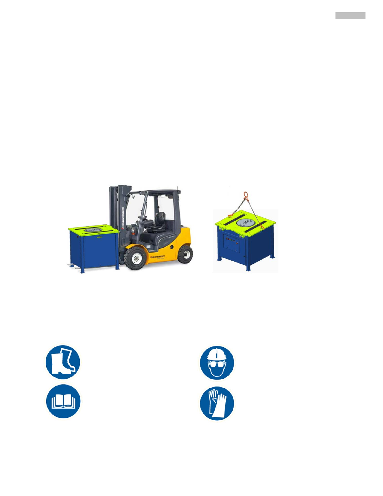
When it is needed to transport the machine for long di s tances by ve hic le s , cra nes or other m e ans of elev a tio n,
the latter should be safe.
By lifting the machine with cranes or hoists, nor malised slings must be used. These are chos en en function of
the required work load limit, the w ay of use and the nature of the load . The choice is correct if special norms of use
are respected. Fig. A
WARNING: To avo id any possible danger, s tay away from elevated lo ads and be careful with their possible
displacement during transpor t, whether during lifting or moor ing. Therefore , it is esse ntial to choose the corr ect slings
and remain particularly vigilant in sens iti v e ope r a tio ns (ele vatio n, coupling, mooring or discharging).
IMPORTANT
: During the transpor t of the machine, the latter should never be rever sed nor be put on either
side. The machine is only to rest on its four feet.
5. PICTOGRAMS.
Pictograms included in the machine entail the follo w ing :
:
READ INSTRUCTION
MANUAL
ITS IS ESSENTIAL
TO WEAR GLOVES
ITS IS ESSENTIA L TO WEAR
SAFETY HELMET AND GOGGLES
MUST USE SAFETY BOOTS
Page 5
7
ENGLISH
6. SUPPLIED WITH MACHINE.
6.1 ASSEMBLY ACCESORIES.
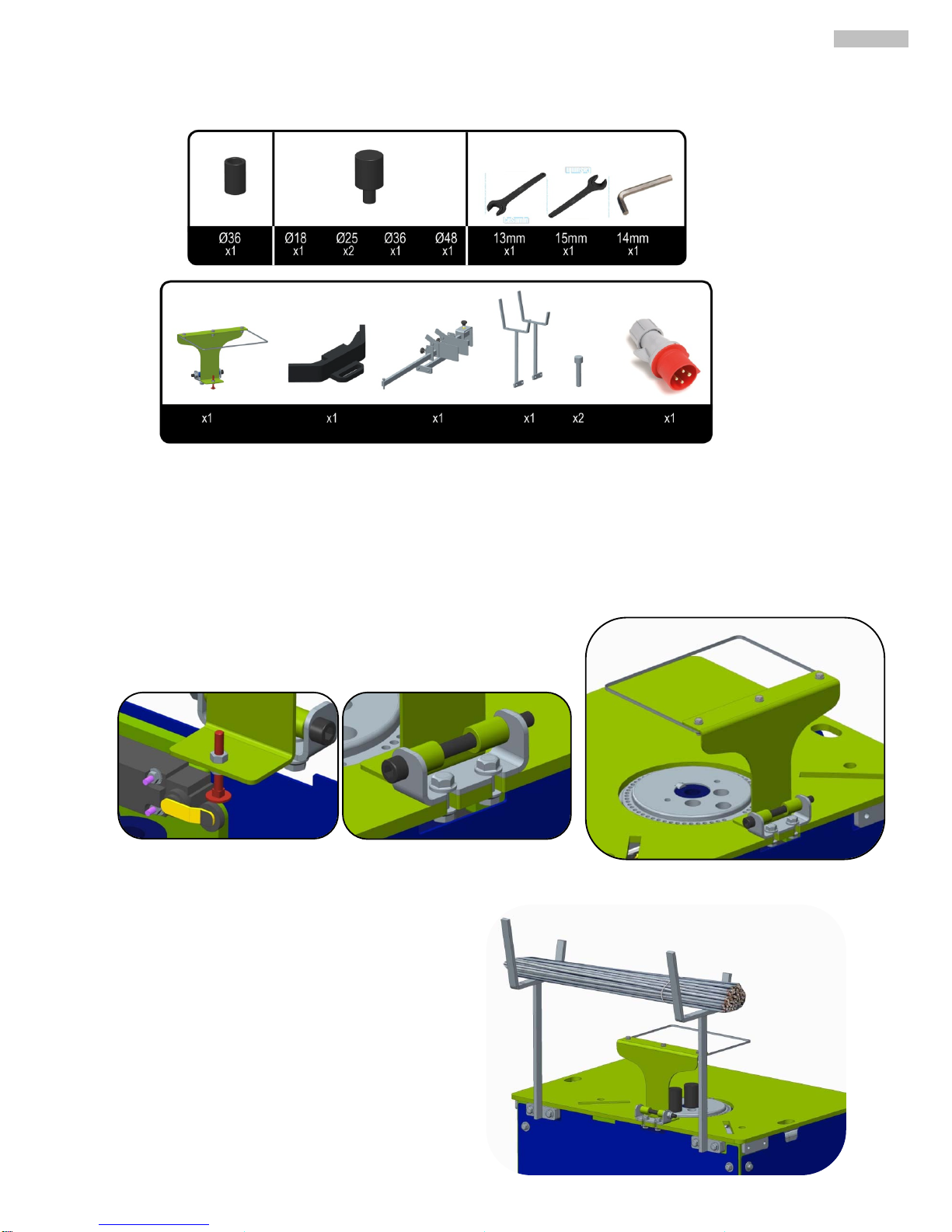
For transport reasons the mac hines is sent with the accessories uninstalled. I nstall the accessories as in the
pictures.
BENDING PLATE PROTECTION: This ne eds to be mounted for the
machine to work. The pro tection presses a micro switch which needs to be
pressed for the machine to work correctly.
BAR SUPPORT: This is for convenience and speed of
productivity
Page 6
8
ENGLISH
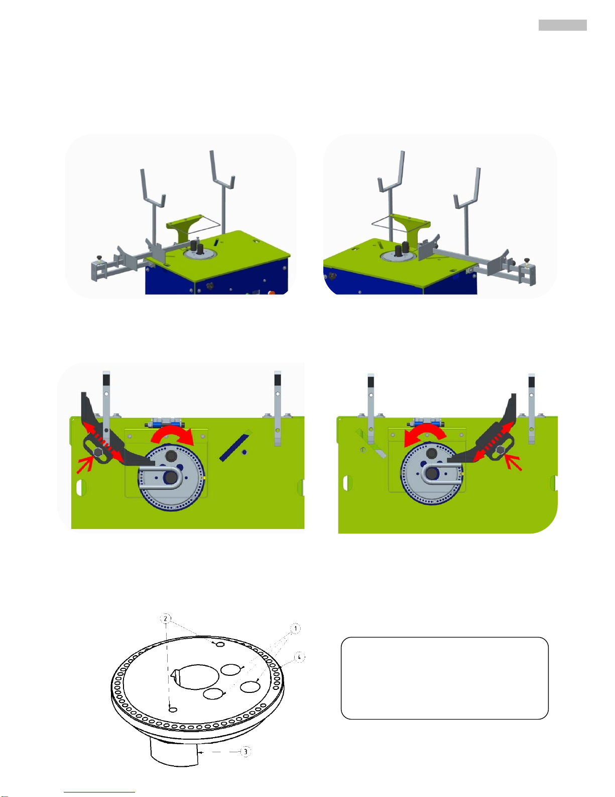
BEND LENGTH MEASURER: The bar length measurer can be mounted on the left or right of the machine. There are
two measuring plates for adjusting length of be nd.
BENDING SUPPORT: The bending support is used for supporting mu ltiple bars for the be nd. The bend ing support
can be mounted on the right or left side. To reposition the bend ing support loosen the screw and slide the sup port
along.
6.2 PARTS OF THE BENDING PLATE.
The plate has many holes for different
purposes.
1. Holes for pushing mandrel. Dep ending on the
size of bar the mandrel can be put in
different positions.
2. Screw holes for extracting the bending plate.
3. Micro plate for stopping.
4. Holes for the pivot bending pin.
Page 7
9
ENGLISH
6.3 INVERSION PIN TO CONTR O L THE BENDING ANGLE.
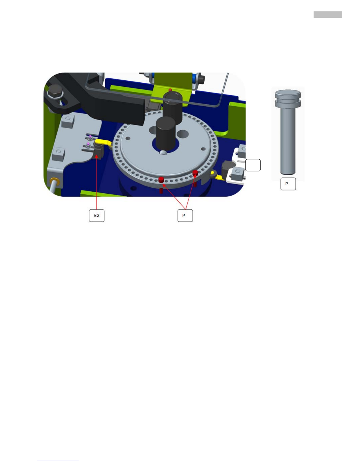
The inversion pin “P” is how we selec t the bending angle of the plate. Depending on if the plate is moving
clockwise or counter clockwise, we have to put the pin on the left or the right of “S2”.
Sensor S2, it to stop the plate turning when the inversion pin P touches it.
Sensor S1, is for stopping the plate when it retur ns to it´s origina l po s itio n.
S1
Page 8
10
ENGLISH
7. GETTING STARTED
WARNING: All safety recommendations must be followed, either the ones mentioned in the present user
manual or those complying with all labour risks prevention norms in every location.
WHEELWORK: SIMA bending and combined machines do not need any wheelwork operations as they are
specially designed to obtain the maximum perform anc e from s tart.
NORMAL USE OF THE MACHINE:
The bending machines have been designed for bending flat and r einforced steel b ars for use in the str ucture
and other construction components
. Each other use that has not been expressively indicated is considered abnor mal.
Any tool or accessory added or amended without written authorization from the manufacturer is considered
inappropriate and dangerous. I f any damage or injury is caused as a result there of or by misuse of the machine , SIMA
S.A. exempts all responsibility as manuf actur er. The m achine mus t be ins talled on a plane, fir m and hor izonta l surface
and the ground should not be soft.
7.1 CONNECTING TO THE SUPPLY
The extension cable used to feed the machine needs to have a minimum section of 4x2.5 mm2 up to 25
meters long. For a superior distance 4x4 mm2 can be used. In one of its ends, it is needed to connect a base
normalized aerial of 3P+T or 3P+N+T compatib le with the machi ne switch and in the other end, one normalize d aerial
pin of 3P+T ó 3P+N+T compatible with switchboard exit.
Machines with electrical motor should always be connected to a normalized switchboard that
disposes of a magneto-thermal switch and a differential in accordance with the characteristics of the
motor:
The machine electrical tension is v isible on the voltage indication ne xt to the top of engine terminals and on
the machine characteristics plate.
WARNING: Do not plug the machine to the electricity if you are not sure of the available electrical
tension. If the tension is n ot cor re c t, the en gine wil l unde rgo irreparable harm or out of service.
TRANSFORMADOR
MOTOR
Don´t connect the machine unless you are sure of the stability of the elec tricity supply
This machine MUST NOT BE USED IN THE RAIN . Cover with waterproof materials. If the machine
has been exposed in the rai n check before connecting the electri c a l pa rt s are not wet. Always work
with good lighting conditions.
Page 9
11
ENGLISH
7.2 CONNECTING TO ELECTRICITY SOURCE.
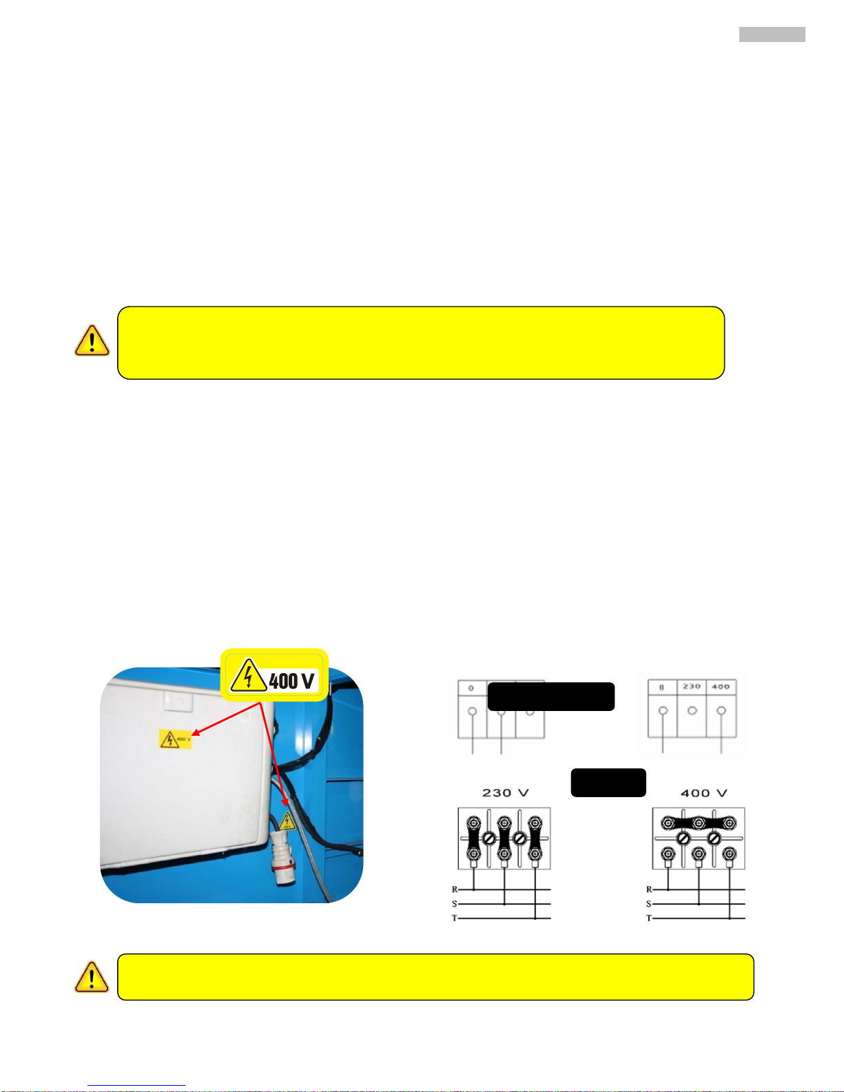
The machine has a display s o that the user can see the voltaje s upplied to the machine before the voltaj e
reached the electrical components and causes any damage.
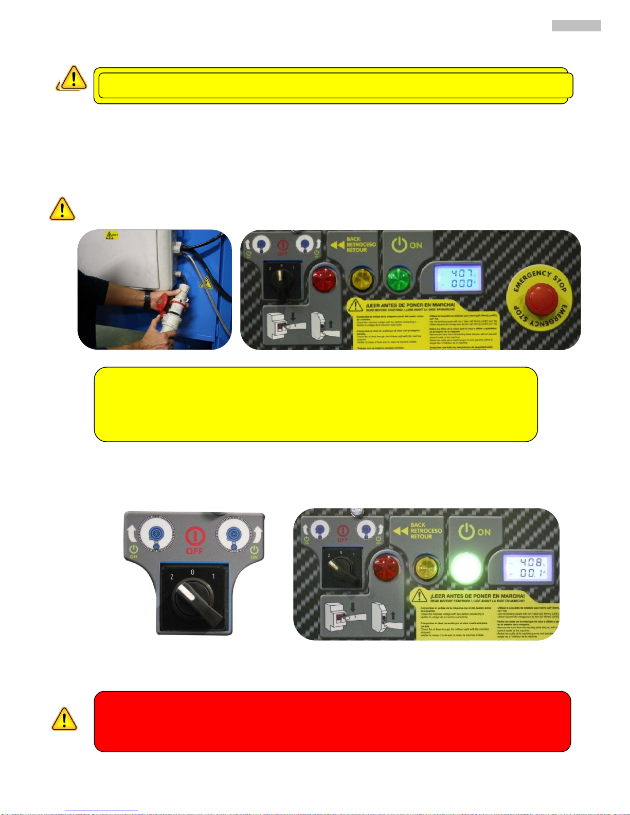
To connect the machine do the following
1. Open the door and connect the socket to the electric al box socket .This way the electri city will not reac h
the motor and you can see the voltage coming into the machine.
2. Turn the black switch to chose the bending dir ection and the green light will shine.
3. Step on the ped al to check which way the plate is t urning. MAKE SURE THERE ARE NO MANDRELS OR
ACCESSORIES ON TOP OF THE MACHINE.
Do not change any elec trical configuration in the machine as this may result in irrep arable damage
When connecting the machine, make sure the machine is turning in the way the sticker indicates, this
will avoid accidents with the accessories on the bending plate.
If it doesn´t turn the right way please change the phases.
VERY IMPORTANT, make sure earth is connected before connected
WARNING: the transformer has a tolerance of
±10%
over and below the specified tension
requirement. If these limits are passed then yo u will bre ak the transf or mer
Machine 400V = 360V min / Max 440V max
Machine 23 0V = 207V min / M ax 253V max
Page 10
12
ENGLISH
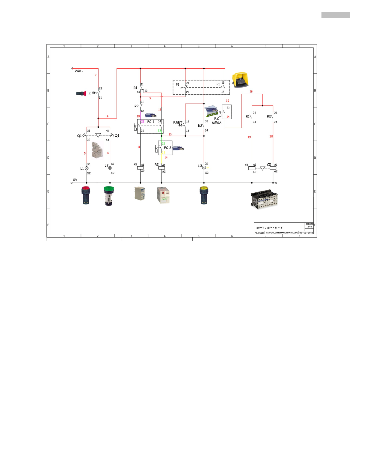
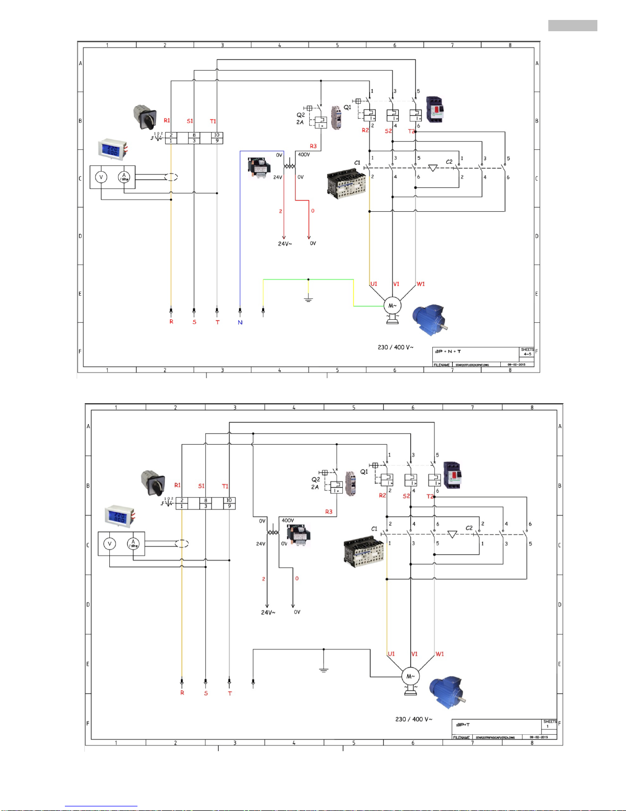
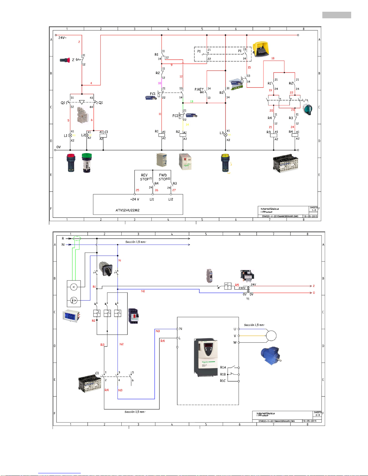
7.3 CIRCUIT DIAGRAMS
Page 11
13
ENGLISH
Page 12
14
ENGLISH
Page 13
15
ENGLISH
MANUAL EMERGENCY RETU RN OF BENDING PLATE
If during the bend yo u want to stop the proc ess press the RETURN butto n and use the pedal to r eturn to a previous
position or to the start.
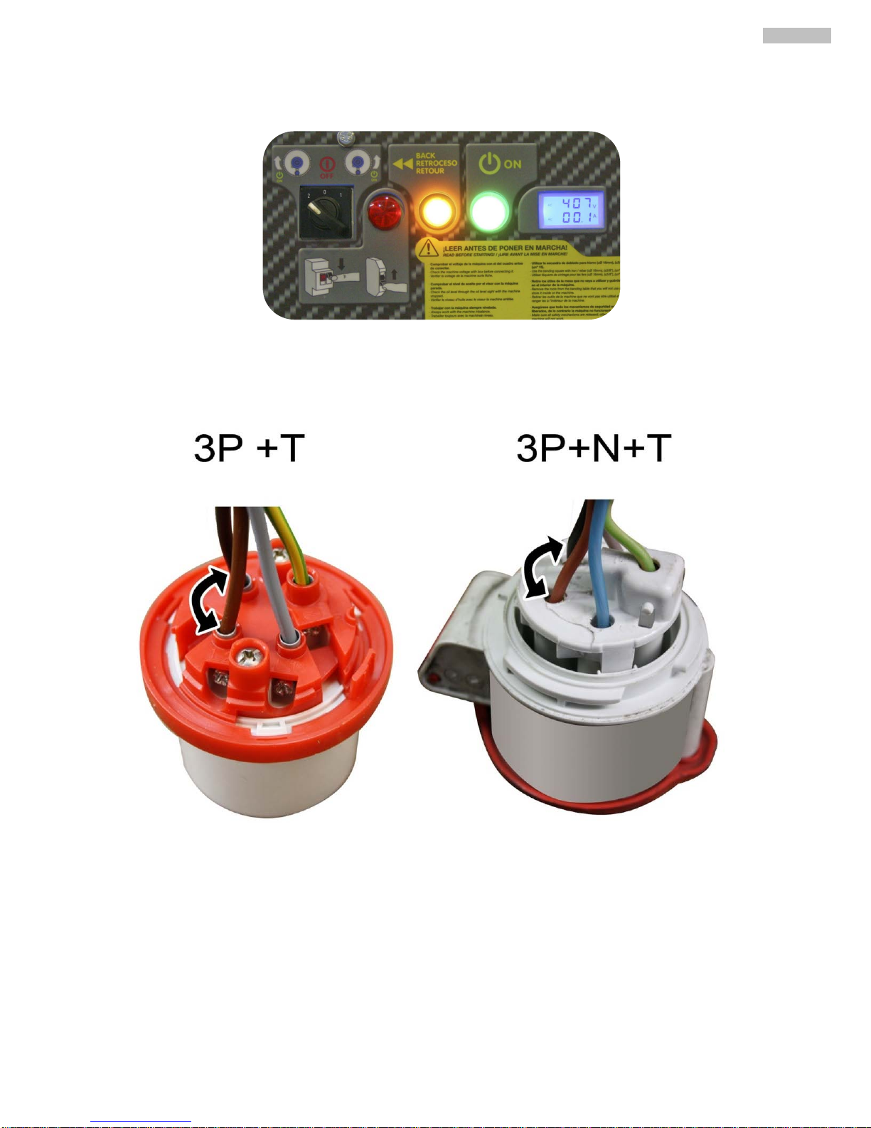
7.4 CHANGING PHASES TO ESTA BL I S H CO RRECT BENDING DIRECTION.
To change the direction of the bend you will ha v e to op e n the co nnecting socket and interchange the wires as show n in
the image.
Page 14
16
ENGLISH
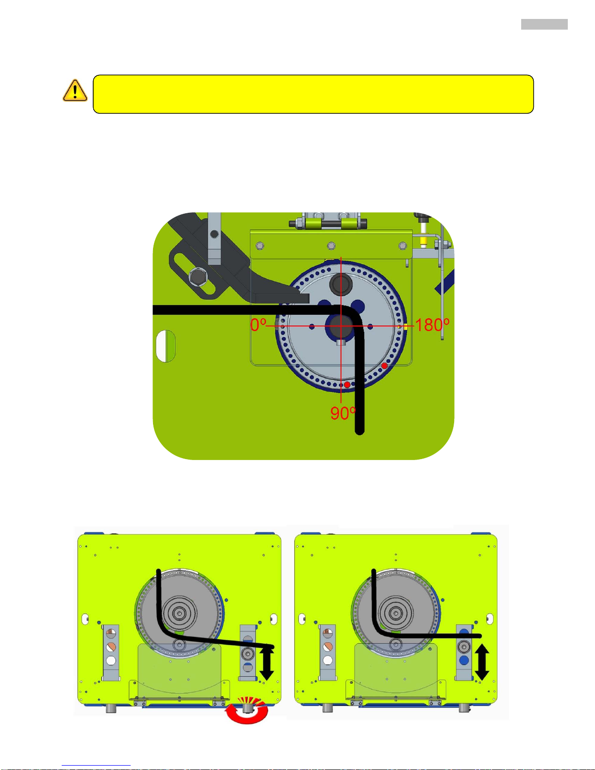
8. MAKING A BEND
1. Divide the bending plate into 4 imaginary 90degree se c tio ns.
2. Select bending direction with the control panel button.
3. Insert the plate pin to the left of 0 degrees so achieve an angle of 90.
4. Step on the pedal and don´ t lift off. The bending plate will move until the pin reaches the inversion
switch.
5. To make the plate return lift your foot off the pedal and press again and the plate will r e turn.
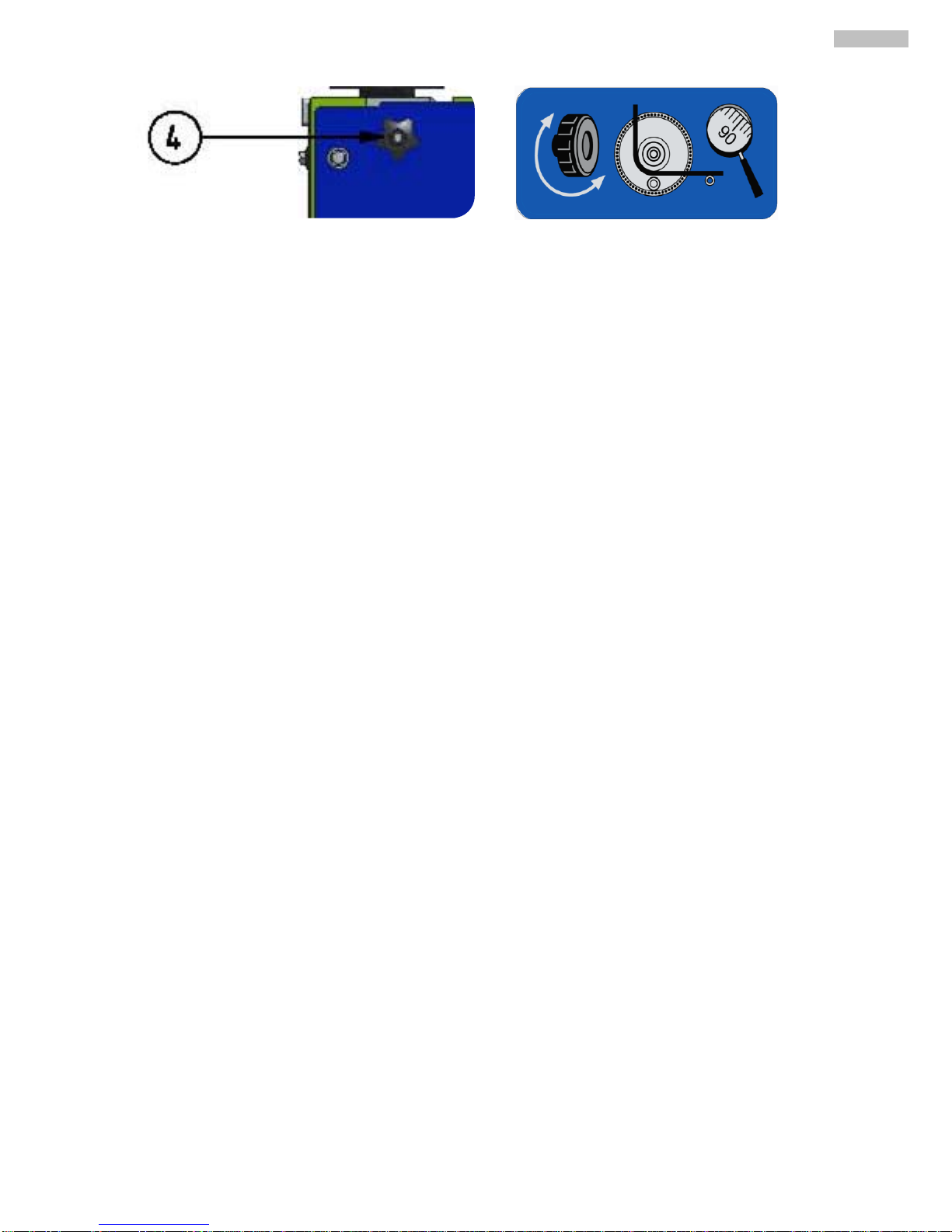
If you haven´t achieved the bend ing angle you require with the pin and y ou need to make a small adjustme nt you can
use the black metal handle s on the side of the machine to move the support ma ndr e ls .
Turn the handle to push the mandrel further away to make a tighter angle and bring it towa rd s to make a
Before starting to bend a rebar make some bends without any acessories on the machine until you are
comfortable with the movement.
Page 15
17
ENGLISH
Page 16
18
ENGLISH
9. MAINTENANCE.
1 Firs t oil c hange a fter 1000 hours of use if mine ral o il is use d and then aga in after 3 000/400 0 hour s if the oil
used is synthetic or a fter 3 years of use if these ho urs aren´t reached. If synthetic o il is used change oil after
20,000 hours.
2 Grease the holes where the pins and mandrels go and als o the bottom of the pins and mandrels , this will
also help avoid build up of rust.
3 At the end of the day disconnect the machine .
4 Cover the m achine at night to protect from rain.
5 When poss i ble remove d ebris form the inside of the machine.
6 Clean the ex terior and grease pins and mandrels frequently..
7 Check the blades on the cutter (every 8 days of use) to see if they need changing.
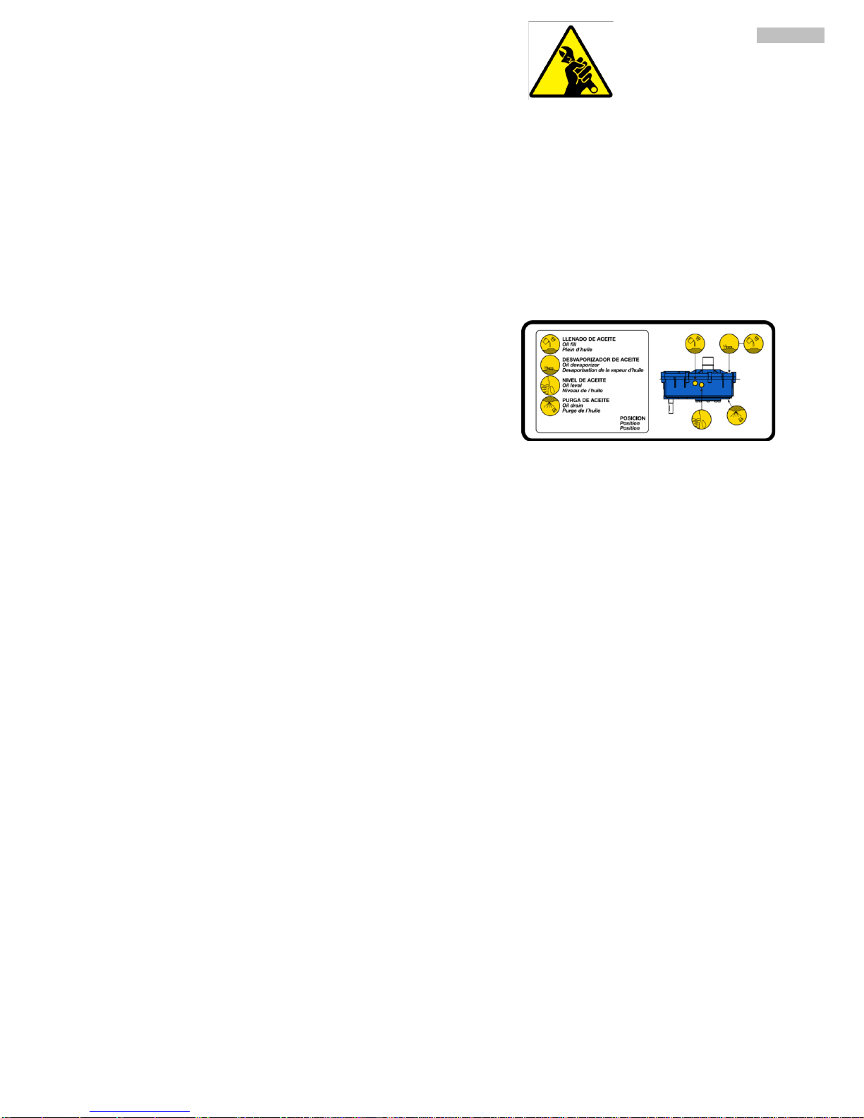
8 Check oil level in the gear box (every m onth) if the level has
gone down be sure to fill up.
Page 17
19
ENGLISH
10. TROUBLE SHOOTING
PROBLEM POSSIBLE CAUSE SOLUTION
Machine won´t bend the bar
Not enough voltage Check supply
Not enough motor power. Check motor is not burnt.
The plate bends but doesn’t return to
its position
The end of bend sensor
Check the end of bend se nsor
The green on light doesn’t switch on
Check cables to the machine, check
supply
Check cables to the mac
hine, check
supply
Pilot light is on but machine doesn’t
work
Machine is not well connected
Machine is only connected in
a single
phase, make sure it is correctly
connected
Connection is correct at 230 or 400
but the machine isn´t moving
Unstable supply
Check the supply, try t
o use a
stabiliser
11. DATA SHEET
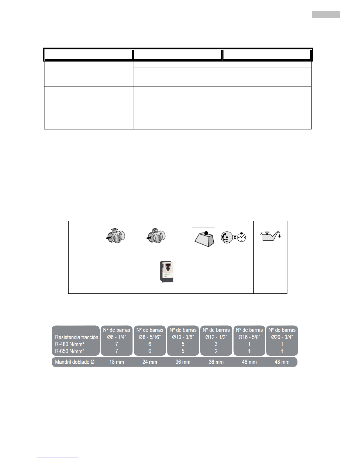
12. BENDING CAPACITY.
STAR-20 1,5Kw Single.
230v
216 Kg. 17 7,5
STAR-20 1,5KwThree. 400v 214 Kg. 17 7,5
Page 18

20
ENGLISH
13. SAFETY RECOMMENDATI O NS
Bending and combined (bending/cutting) machines should b e used by trained people or people familiarized
with their operation.
• Before starting up the machine ple as e read the ins tructions and make sure safety norms are respec ted . Le arn how to
stop the machine in a fast and safe way.
• Place the machine on a plane surface. Connect the machine to the electrici ty only when you are sure of its stab il ity .
• Start the machine only when you have mounted the safety guards that come with the machine.
• It is recommended to use safety glasses, safety boots, gloves etc. Please always use approved materials.
• Always use Individual Protection Equipme nt (IPE) in ac co rd anc e with the typ e of work you are effe c tuating.
Prohibit strangers to acces s the p la ce of work of the machine.
Work clothes are not supposed to hav e loos e ar tic le s that can cling into mov able par ts of the machi ne .
When you have to move the machine, unplug the electricity cables and block the moving parts of the
machine.
Always keep protection e lements and the safety guards in their correct positions.
Attention: Before placing the bolts, mandrills and the bending squares, check the direc tion of rotatio n of the
bending plate. You can then install the suitable ac c ess or ie s for the type of work you wa nt to make.
The damaged electrical cable s sho uld b e urge ntly repla c e d .
Unplug the machine fr om the electricity and never manipulate nor operate o n the mechanical nor electrical
elements of the machine while the engine is on.
Never use the machine for purposes other than thos e it has been des igned for.
• VERY IMPORTANT: Earth should always be connected before switching on the machine.
• Use correct connection cable
• Check the electricity supply to the mac hine and make sure it is the same as indicated on the serial number
plaque or sticker.
• Make sure the cable is secure from direct hear, oil, footfall.
• Don´t use pressurised water to clean the machine as this may get into the elec tric al com po ne nts .
ATTENTION: You are to follow all safety recommendations mentioned in the present user manual
and comply with all labo ur r isks pr e vention norms in ever y loca ti o n.
SIMA, S.A. is not responsible for the consequences possibly generated but the inadequate use of
the bending or the combined (bending/cutting) machine.
Page 19

21
ENGLISH
14. WARRANTY
SIMA, S.A. the manufacturer of lig ht machine ry for constructio n po ssesses a ne t of technic al ser vi ces “S ERVI-
SIMA”.
Repairs under warranty made by SERVÍ-SIMA are subject to some strict condition to guaranty a high q uality
and service.
SIMA S. A. guarantees all its products against any manuf actur ing defect; to take into account the conditions stated in
the attached document “WARRANTY CONDITIONS”. T he latter wo uld ce a se in case of failur e to comp ly with the
established payment terms. SIMA S.A. reserves its rig ht to br ing modifications and changes to its products without
prior notice.
15. SPARE PARTS
The spare parts for the bending and combined machines, manufactur e d by SIMA , S.A. are to be found in the
spare parts plan, attached to this manual.
To order any spare part, please contact our alter-sales service clearly indicating the serial number of the
machine, model, manufacturing number and year of manufacturing that show on the serial number plaque
or sticker.
16. ENVIRONMENT PROTECTION
Raw materials have to be collected instead of throwing away resid uals. Instruments, acces sories, fluids and
packages have to be sent into specific places for ecological reuse. Plastic components are marked for
selective recycling.
R.A.E.E. Residuals arising of electrical and electronic instruments have to be stored into specific
places for selective collection.
17. DECALARATIONS ON NOISE
The acoustic levels emitted by the MACHINE are inferior to 70 dB (A)
18. DECLARATIONS ON MECHANIAL VIBRATIONS
The machine does not pre sent any source of mec hanical vibratio ns that cause r isks to the health o r safety of
the operator.
Page 20

22
ENGLISH
 Loading...