

Sima Safety Kit User manual
STS Titanium Power Inverters
Inverter Installation Safety Kit
for 1000 – 1500 – 2500 Watt Inverters
General: The Inverter Installation Safety Kit is designed for installation of DC to AC power inverters up to 2500 watts. The wires and
connectors included with this kit will improve the performance and extend the useful life of the DC to AC p ower system which
includes the vehicle’s batteries and charging system, the cable connectors, the power inverter and the load (TV’s. VCR’s, microwaves
etc.). Using the proper fuse inside the fuseholder will protect the vehicle and contents from damage caused by shorted wirin g.
Caution: If you are not familiar with 12V high currency wiring, please contact a
professional inst alle r for assi st ance
Required tools: Crimping tool or soldering iron for soldering Drill and drill bits
Adjustable wrench with insulated handle Knife or wire stripper
Phillips and slotted screwdrivers 4 mounting screws for power inverter
Black electrical tape 2 mounting bolts and nuts for fuse holder
Hacksaw
Explanation:
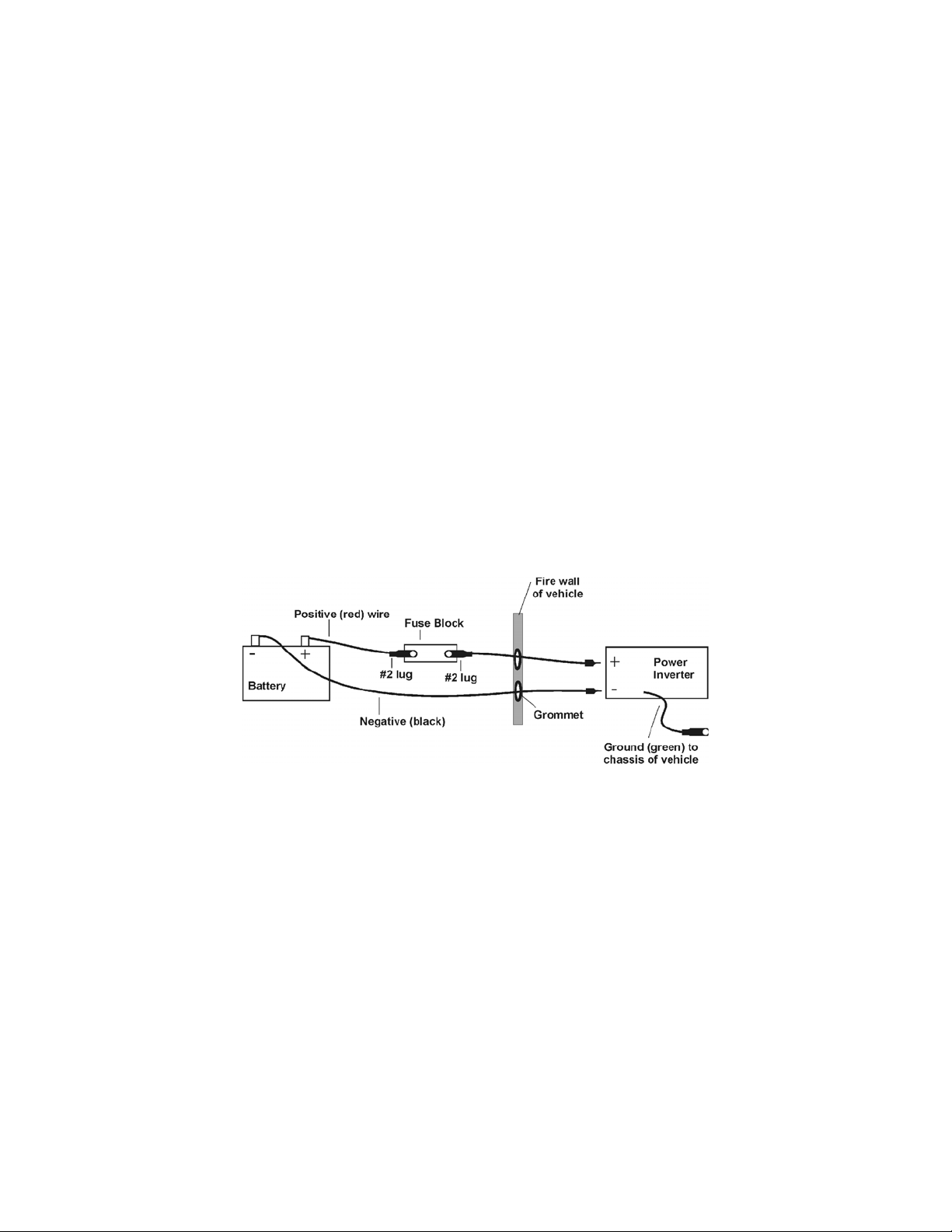
a. The short red wire is to go from the positive terminal of the battery to one side of the fuseholder.
b. The fuse inside the fuseholder protects your vehicle from damage caused by accidental shorting of the long red wire to
ground. (Use 150 amp fuse for 1000 and 1500 watt inverters. Use 200 amp fuse for inverters up to 2500 watts.)
c. The long red wire is to go from the other side of the fuseholder to the positive terminal of the power inverter.
d. The black wire is to go from the negative terminal of the battery to the negative terminal of the power inverter.
e. The green wire is to go from the chassis ground of the vehicle to the ground terminal of the power inverter.
Connectors:
• All of the connectors are made from high quality copper and covered with anti-corrosion coating.
• Two of the connectors have larger holes (3/8”) for connection to the battery.
• Two of the connectors are wedge shaped. These are to be used if your power inverter has the screw-down terminals.
Instead of tightening directly to the wires, using these connectors will prevent loosening over time.
Grommets: The grommets are very important. Make sure to use the grommets to protect the red and black wires when going through
holes drilled in metal.
Preparation: Find a location for fuseholder near the battery.
Find a location for the power inverter inside the vehicle.
Drill holes for routing the red (+) wire and black (-) wires from the battery into the vehicle. Make sure to use black
rubber grommets to protect the wires from rough metal edges which could strip or cut the wires and cause a short
circuit. The green wire is the ground and no grommet is needed.
Use a hacksaw to cut wires to required lengths. Remember: Too long is much better tha n t oo short.
Strip back insulation 5/8” on ends of wires.
Common sense: Never work on electrical wiring in the rain or while drinking or under medication.
Never work on electrical wiring while connected to the battery.
The last connection is always the connection to the positive terminal of the battery.
Warranty: The components of the safety kit – excluding the fuses - are warranted for one year to date from the date of purchase.

Before Starting Installation, Turn Power Inverter Off!
Disconnect red positive (+) cable from Battery
THESE INSTRUCTIONS ARE FOR NEGATIVE GROUND 12 VOLT ELECTRICAL SYSTEMS
(The negative terminal of the battery is connected to the chassis or engine housing)
1. Crimp or solder connectors to both ends of short red wire and one end of long red wire and one end
of black and green wires.
2. Mount fuseholder to secure place near battery.
3. Mount Power Inverter inside vehicle. Most Power Inverters can be mounted horizontally, vertically
or upside down.
4. Remove fuseholder cover. Remove top nut and top washer on fuse posts. Use 150-amp fuse for Power
Inverters up to 1500 watts. Use 200-amp fuse for Power Inverters up to 2500 watts. Place fuse on top
of bottom washer on both posts. Place connector on short red wire on fuse end on post nearest
battery. Place washer on top of connector and tighten nut. Place connector on long red wire on fuse
end of remaining post. Place washer on top of connector and tighten nut. Replace fuseholder cover
and secure cover with cable ties or electrical tape.
5. Connect the black wire connector to the negative terminal (-) of the battery.
6. Connect the green wire connector to the chassis ground of the truck. The chassis ground is the point
where the wire from the negative terminal of your battery is connected to the metal frame or engine.
7. Route the long red, black and green wires to the Power Inverter. Crimp or solder the connectors on
all wires.
8. Connect the red wire connector to the red terminal of the Power Inverter. Tighten securely.
9. Connect the black wire connector to the black terminal of the power inverter. Tighten securely.
10. Connect the green wire connector tot he ground (copper) connection on the power inverter.
11. RECHECK CONNECTION AND MAKE SURE THE RED WIRE OR ITS CONNECTORS ARE
NOT TOUCHING ANY METAL PARTS OF TH E VEHICLE OR THE BLACK WIRE
CONNECTORS.
12. Make sure the power inverter is OFF. Connect the end of the short red wire to the battery. BE
CAREFUL! There is normally a spark at this time.
13. Turn the Power Inverter ON.
Please note that this Safety Kit is a patent pending de sign and is an exclusive product of
SPC Subsidiary Corporation
140 Pennsylvania Ave.
Bldg. #5
Oakmont, PA 15139
1-800-391-3650
 Loading...