

Page 1
SIM-04
DIGITAL DUAL DETECTOR
PIR AND MICROWAVE
INSTALLATION INSTRUCTIONS
P/N 7106762 Rev A
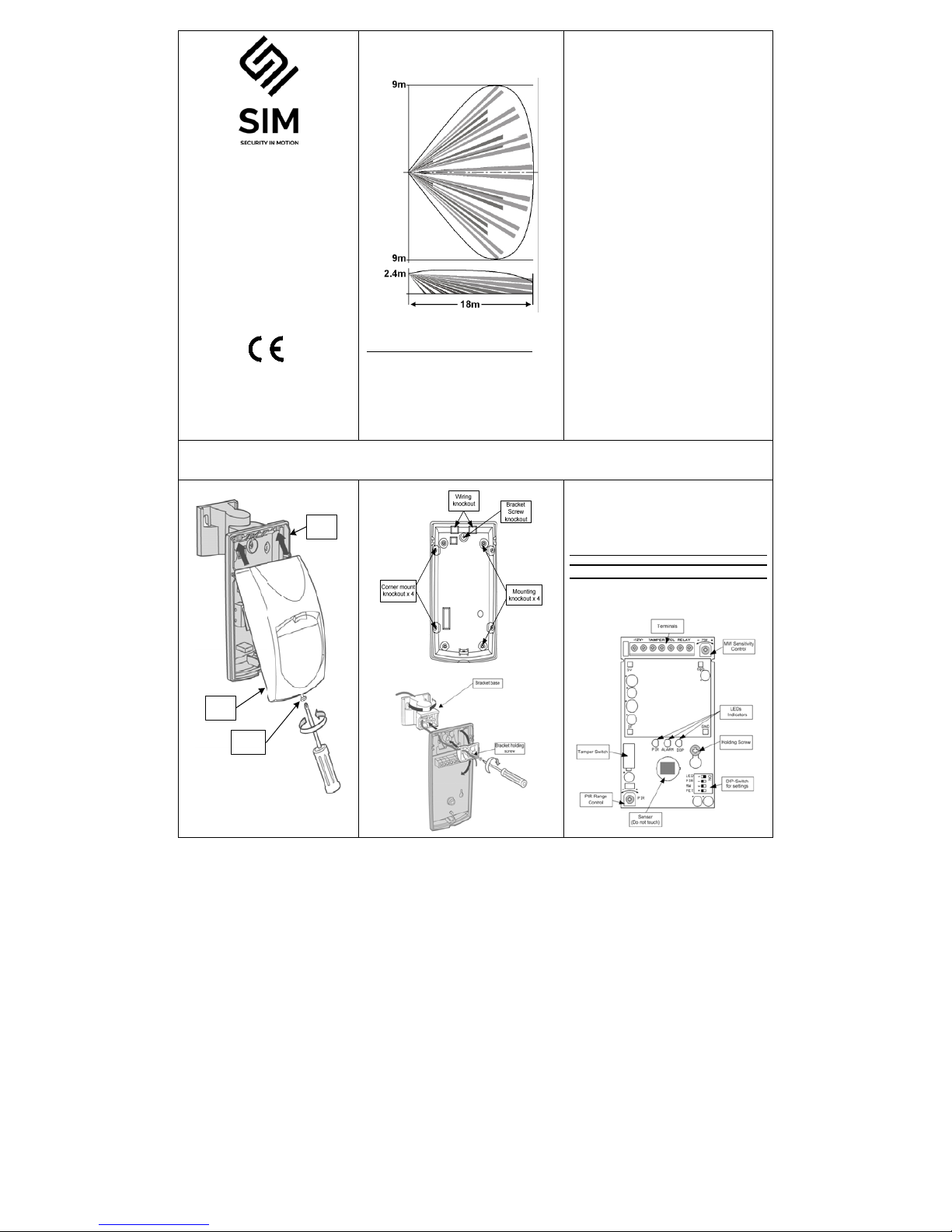
Wide Angle Lens
AVOID THE FOLLOWING LOCATIONS:
Facing direct sunlight.
Facing areas that may change temperature rapidly.
Areas where there are air ducts or substantial
airflows.
Avoid screen, curtain that may block detection area.
Do not install outdoors.
SPECIFICATION
Detection Method PIR element &
microwave pulse
Doppler
Power Input 8.2 to 16 Vdc
Current Draw Active : 25.5 mA
Standby: 16.5 mA
Temperature
Compensation YES
Alarm Period 2 +/- 1 sec
Alarm Output N.C 28Vdc 0.1 A
with 10 Ohm series
protection resistors
Tamper Switch N.C 28Vdc 0.1A
with10 Ohm series protection
resistor - open when cover is
removed
Warm Up Period 1 min
LED Indications
Yellow blinking during warm up period and self
testing
Red LED: ON during alarm
Green LED: PIR CHANNEL
Yellow LED: MW CHANNEL
Dimensions 115mm x 61mm x
37.5mm
Weight 120g
INSTALLING THE DETECTOR
Holding
Screw
Cover
Base
WIRE REQUIREMENTS
Use #22 AWG (0.5mm) or wires with a larger
diameter. Use the following table to determine
required wire gauge (diameter) and length of wire
between the detector and the control panel.
Wire Length m 200 300 400 800
Wire Diameter mm .5 .75 1.0 1.5
Wire Length ft 800 1200 2000 3400
Wire Gauge # 22 20 18 16
PCB LAYOUT
Page 2
WIRE CONNECTIONS DETECTOR SETTINGS
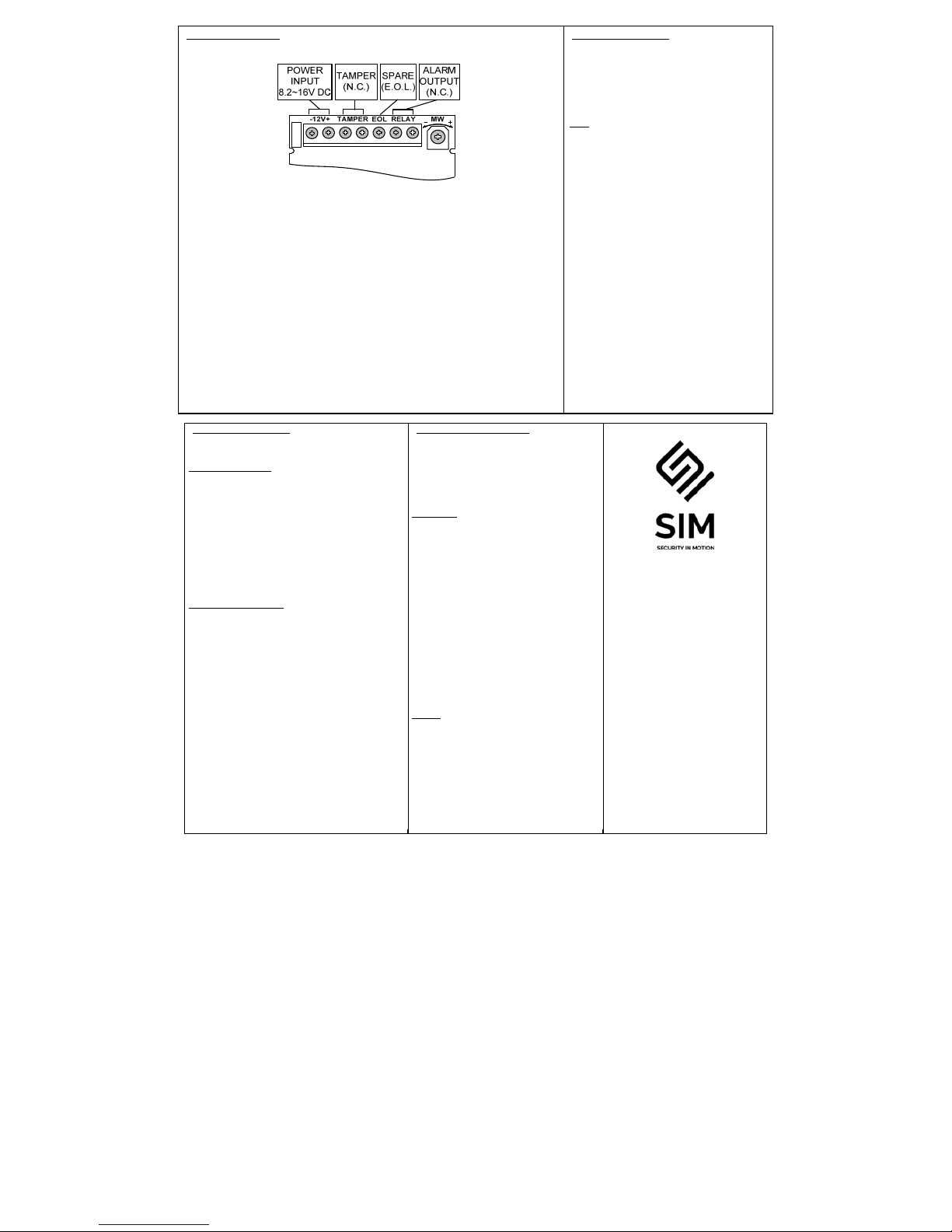
Terminal 1 - Marked - (GND)
Connect to ground of the control panel.
Terminal 2 - Marked + (+12V )
Connect to the positive Voltage output of 8.2 ~ 16Vdc source.
Terminals 3 & 4 - Marked TAMPER
Connect these terminals to a 24hour normally closed protective zone in the panel.
Terminal 5 - Marked EOL
End of line option.
Terminals 6 & 7 - Marked RELAY
These are the output relay contacts of the detector.
Connect to the control at zone input.
Switch 1: LED Control
Position Right – ON - LEDs ENABLE
The RED LED will activate when the detector
is in alarm condition.
Position Left – OFF - LEDs DISABLE
Note: the state of the switch “LED” does not
affect the operation of the relay.
Switch 2: PULSE count for PIR.
Position Left – OFF. High sensitivity
2 PULSES - for normal stable environment.
Position Right – ON. Low sensitivity
3 PULSES - for harsh environments.
Switch 3: MW range control according to the
room size.
Position Left – OFF – Long
For room size 10m – 18m.
Position Right – ON – Short
For room size 5m – 9m.
Switch 4: the PET Immune function
Position Right - ON - Immunity up to 15 kg
Position Left - OFF - Immunity up to 25 kg
RANGE ADJUSTMENT
PIR SENSITIVITY
Use the Potentiometer marked “PIR” to adjust
the detection sensitivity between 15% and
100%, according to walk test in the protected
area.
Factory setting is 57%.
MW SENSITIVITY
The “MW” potentiometer adjusts the detection
sensitivity of Doppler between 40% and 100%
(factory set to 65%).
Rotate the potentiometer clockwise to
increase sensitivity.
Rotate the potentiometer counter- clockwise
to decrease sensitivity.
TESTING THE DETECTOR
Apply 12 Vdc power to the detector,
wait 2 minutes to finish the detector
warm up time. Conduct testing with the
protected area cleared of all people.
Walk test
1. Remove front cover.
2. Make sure that PULSE switch is in
position 1.
3. Make sure that LED switch is ON.
4. Replace the front cover.
5. Start walking slowly across the
detection zone.
6. Observe that the detector’s LED
lights whenever motion is detected.
7. Allow 5 sec. between each test.
8. After the walk test is completed, the
LED and PULSE jumpers may be
changed.
NOTE: Walk tests should be
conducted, at least once a year, to
confirm proper operation and coverage
of the detector.
www.sim-security.net
 Loading...