

SIM INSPIRE-32W Installation Manual
INSPIRE-32W
QUICK INSTALLATION GUIDE
This manual is a part of manuals set.
Read carefully all manuals before install the product.
This product is designed for indoor use only.
01 BOX CONTENT
1 x INSPIRE-32W Panel
1 x AC Cable
(already plugged)
1 x RJ45 Ethernet Cable
1 x Battery backup
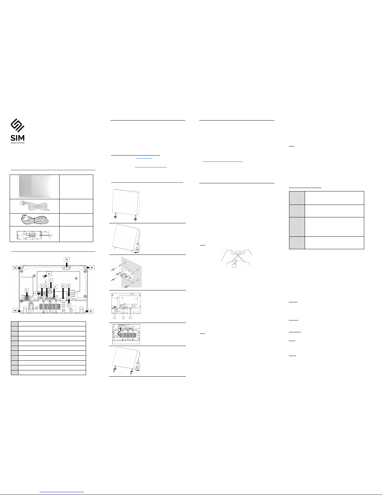
03 PANEL OVERVIEW
Rear View
1
Power AC connection
2
Water Level indicator for wall mounting
3
Battery connector
4
SIM Card slot for Micro SIM Card
5
SD Card Memory slot (Not available)
6
RJ45 Ethernet connector (connect to router)
7
Tamper Switch for cover removal protection
8
Learn Device button (not enabled)
9
WPS
10
Hole for screw wall mounting
11
LED Indicators (see Installation Manual on page 5)
02 BEFORE THE INSTALLATION
INSPIRE-32W must be installed close to a power socket and
connected to an Internet connection through Ethernet RJ45 cable,
Wi-Fi or GPRS.
If you wish to use GSM/GPRS feature please install a micro SIM
card (not supplied) into your panel and make sure that the quality of
reception is sufficient.
The internet connection allows the installer to configure and the
end-user to remotely monitor and control the INSPIRE-32W panel.
The connection to the panel can be done via:
Web Personal page at www.XXX.com
Smartphone Android or Ios ("XXX" mobile application)
Tablet Android App ("Inspire keypad").
Installer Web page at www.stage-installer.XXX.xyz
03 INSTALLATION AND CONNECTION
Unscrew the holding screws
Tilt Out the panel cover
Place the unit on the wall and use
the water level indicator to position
it straight.
Mark the holding holes on the wall
and drill the wall.
Mount the unit on the wall with
screws
Ethernet – Connect the Ethernet
cable to a router or an internet
outlet
GSM – Insert micro-SIM card into
the SIM card slot
AC – Plug into a power outlet
Connect the backup battery
Insert back the front cover by tilting
it inside
Close the 2 holding screws
Connect the panel to AC Power
04 PANEL CONFIGURATION
After mounting the INSPIRE-32W panel, connect it to the AC and
to the internet via the Ethernet cable plugged into the router.
The panel is configured to automatically connect and register on
the cloud.
The configuration of the INSPIRE-32W panel has to be performed
through the web installer interface.
Please refer to your local distributor for information and credentials
to https://stage-installer.xxx.xyz/#!/login
Please unscrew the mounting bracket from the panel. Then lift the
two notches located on the both sides of the bracket
05 QUICK PROGRAMMING
Enter the installer code (by default the code is 000000).
Installer code
For security reasons, it is highly recommended to change the
installer code.
Go to "Miscellaneous" and change the installer code in Panel
Options and submit.
Users codes and names ________________________________
Inspire panel can manage up to 16 users.
Click on User to change its code and name
Learn remote pendant by inserting its unique ID number
Click "Submit" to save changes and activate users and pendants
Note: to activate pendants, press on the two lower buttons.
Areas Names _________________________________________
INSPIRE-32W panel offers up to 4 areas (partitions)
Select the Area to change its name (Ex: Home)
Zones _______________________________________________
INSPIRE-32W panel offers up to 64 wireless zones (32 ISM and 32
DECT ULE)
Click on required zone to display its options.
Insert unique ID number of the device and give it a name.
Set up working mode of the zone (Stay mode, 24-hour…)
Specify Area activation assignment
Note:
The pairing of DECT ULE device must be preliminarily performed
from "Communication" → "DECT" → "Learn DECT Device".
When the DECT device pairing is done, then you can go to "Radio
Zones" and assign the DECT device ID to a zone between zones
33 to 64.
Click "Submit" to save changes and activate learned zones.
Outputs ______________________________________________
INSPIRE-32W panel offers up to 32 wireless outputs
(16 ISM and 16 DECT ULE AC Smart Plugs)
Click on required output to display its options.
Insert unique ID number of the device and give it a name.
Note:
The pairing of DECT ULE device must be preliminarily performed
from "Communication" → "DECT" → "Learn DECT Device".
When the DECT device pairing is done, then you can go to "Outputs"
and assign the DECT ID to an output between 17 to 32.
Report Channels _______________________________________
INSPIRE-32W panel offers 4 reports channels types for events
communication.
Click on a report channel to display its options.
Select channel type as follow:
TCP / IP
Set channel type as TCP/IP
Need to set Ethernet enabled to use this type of
channel
Wi-Fi
Set channel type as Wi-Fi.
Need to set Wi-Fi enabled to use this type of
channel
GPRS
Set channel type as GPRS 3G
Need to set 3G IP enabled to use this type of
channel in setting "Communication" → "GSM"
(see below in para "Communication")
SMS
Set channel type as SMS Text Messages
Active the channel and destination address or phone number
Select the operated protocol ("Crow" by default. Change it if
needed for connection to monitoring station)
If the selected channel is a backup of another channel, you can edit
it.
Communication _______________________________________
Default remote access password is "12345678", we recommend
modifying it.
Activate communication paths configured in "Report Channels".
TCP/IP:
By default, the DHCP is active; the router will assign the internal IP
of the INSPIRE-32W. You can assign a dedicated IP address to the
panel by filling its static IP, Subnet mask and its Gateway (address
of the router).
GSM IP:
This option activates the GPRS. Fill the APN received of your
provider.
GSM SMS:
This option activates SMS features if enabled in "Report Channels".
Wi-Fi:
The Inspire™ panel can connect to the router in Wi-Fi.
Fill the network SSID (name of the wireless network), Security type
and network password.
DECT:
Learn DECT devices and go to "Zones" or "Outputs" to assign
paired devices.
RF Repeater:
The Inspire™ panel can support up to 4 wireless repeaters. Insert
the ID number of repeater. In case of jamming, you can adjust the
RF Channel frequency range between 1 to 5.
Diagnostic __________________________________________________
After submitting the configuration, check connections status of the panel:
Battery Status
Ethernet network status with internal connection status.
Wi-Fi connection status
GSM and GPRS status with RSSI level
ISM 2-Way Wireless Radio information
Walk Test ___________________________________________________
Check Zones connection status, device type and RSSI signal of each ISM
detectors.
Click on "Start Walk Test" to start the test.
By cross-walking all of the detectors connected to the system and
activating them, the associated zone will latch up to allow verification that
all zones are working properly.
Press "Exit & Stop Walk Test" button, the walk-test mode will be terminated
The results of the walk-test will be displayed on the screen to verify which
detectors were triggered during walk-test mode
06 WEB SERVICES
End User Personal Web Page
Your INSPIRE panel is configured by default for direct communication to
Cloud.
After configuration of your panel, go to http://xxx .com and proceed with the
user registration to your Inspire™ panel.
The Cloud personal user webpage give to the end user direct
access to all of its registered control panels.
This personal webpage offers to the end user possibility to:
Connect to its registered control panel
Monitor and Control panel and connected devices
Browse alarm pictures and request for immediate take picture
Get panel connection info
Manage cloud users
Login:
If you already have an account on Cloud, fill these form
Sign up:
Click this link to start registration of new user
Forgot Password:
Click this link to retrieve your password
Language:
Select your preferred language
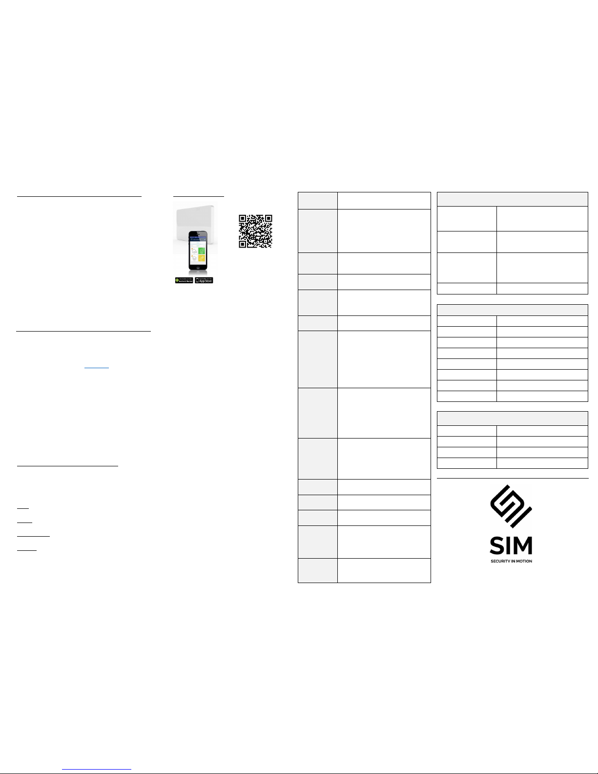
Mobile Applications
Smartphone iOS and Android
Install the Mobile application on
your smartphone
(iOS / Android)
Features ____________________________________________________
Users
Up to 16 users
Codes and/or pendants
Zones
Up to 64 2 Way Wireless Zones
Up to 32 ISM (RF) zones
Up to 32 DECT zones
Working modes (normal, 24H, Chime…..)
Remotely zone configuration
Zone supervision
Areas
Up to 4 Partitions (areas)
With Area Name customization
Arming Modes
Total, Stay, Latchkey, Duress, Bypass
Outputs
Up to 32 Two Way Wireless Outputs
Up to 16 ISM (RF) outputs
Up to 16 DECT outputs
Visual verification
Up to 8 indoor or outdoor PIRCAM detectors
Communication
GSM / GPRS 3G
Ethernet
WI-FI
SMS Control Commands
Report Channels
Up To 8 report channels
TCP/IP channel
Wi-Fi channel
GSM/GPRS channel
Backup between communication methods
SMS
Full Duplex voice call (with DECT Panic devices)
Protocols
Multi-protocol support to CMS
CROW
Contact ID
SIA DC09 – SIA DCS (03)
SIA-09 (ADM-CID)
programmable reporting options
Mobile Apps
iOS / Android / Web
Programming
Via Web browser interface
Log Events
2000 events
Time Zones
Up To 8 Time Zones
Time zone for Area - Arm/Disarm
Time zone for an output
Time zone for user
Mounting
Desk / Wall mount
With Front & Back tamper protection
Technical Specification _________________________________________________
WIRELESS CAPABILITIES
Communication Protocol
Two Way ISM
GFSK with 5 frequencies & LBT
DECT ULE
ISM Frequency Bands
868MHz
DECT Frequency Band
Europe: 1880-1900 MHz
Operating Range
Up to 600 meters open space
ELECTRICAL
Power Input
110V÷230V AC 50/60Hz
Power Supply Type
Internal AC/DC Adaptor 6V/2A
Low Battery Threshold
3.6V (±0.1V) DC
Backup Battery Type
Battery Pack 3.7V/2600mAh
Time to Charge
24 hours
Battery Autonomy
More than 12 Hours ( w/o DECT active)
Battery Charge Max current
Approx. 500mA
Current Consumption
Average: 120mA (with DECT active 230mA)
PHYSICAL PROPERTIES
Dimensions
233.8 x 165.8 x 31.6 mm
Weight
1.40Kg including battery
Operating Temperature
-10° C to 55 °C
Storage Temperature Range
-20 °C to 60 °C
www.sim-security.net
 Loading...