

SIM 2W-SIROUT-S Installation Manual
i
2W-SIROUT-S
Two Way Outdoor Sounder With Battery
INSTALLATION MANUAL
P/N 7106663 Rev A

i
Contents
INTRODUCTION ...................................................................................................................... 2
GENERAL DESCRIPTION........................................................................................ 2
2W-SIROUT-S INTRODUCTION TO RUNNER 2
........................................................... 2
SIREN UNIT DESCRIPTION.................................................................................... 3
SETTING THE 2W-SIROUT-S FOR RUNNER 2
CONFIGURATION
...................................... 3
STEP 1: FW2-TRANSCEIVER – LEARNING & OPERATING MODE FOR
RUNNER 2 ONLY ............................................................................................ 3
PHYSICAL DESCRIPTION ........................................................................................................ 4
STEP 2: SETTING THE SIREN CONFIGURATION MODE ............................................... 4
STEP 3 : LEARNING THE SIRENS ........................................................................... 6
FUNCTION TESTING AFTER LEARNING. .................................................................... 6
SETTING THE 2W-SIROUT-S FOR SERENITY
CONFIGURATION
...................................... 7
SETTING THE 2W-SIROUT-S CONFIGURATION
............................................................. 7
LEARN THE 2W-SIROUT-S WITH SERENITY C.P
........................................................ 8
FUNCTION TESTING AFTER 2W-SIROUT-S
LEARNING
.
.................................................
10
INSTALLATION INSTRUCTIONS ........................................................................................... 11
INSTALLING THE T
RANSCEIVER
............................................................................ 11
INSTALLING THE SIREN UNITS ............................................................................ 12
MAINTENANCE14
LOW BATTERY INDICATION................................................................................. 14
CHANGING THE SIREN BATTERY........................................................................... 14
ERASING THE SIREN
M
EMORY
.
............................................................................ 14
ERASING THE TRANSCEIVER M
EMORY
. .................................................................. 14
SPECIFICATION: SIREN UNIT .............................................................................................. 16
SPECIFICATION: TRANSCEIVER UNIT.................................................................................. 17
2
Introduction
General Description
The 2W-SIROUT-S can be assigned SIM control panels.
it requires the SIM TX/RX-PB-S installed in the SIM.
The 2W-SIROUT-S unit can be powered by Lithium Battery 3.6V/14Ah or by external
power supply 12V/0.8A or both.
SIM TX/RX-PB-S Introduction into the SIM Panel
SIM TX/RX-PB-S can be installed in selected SIM panel or in an external box while protected
by the on boards tamper
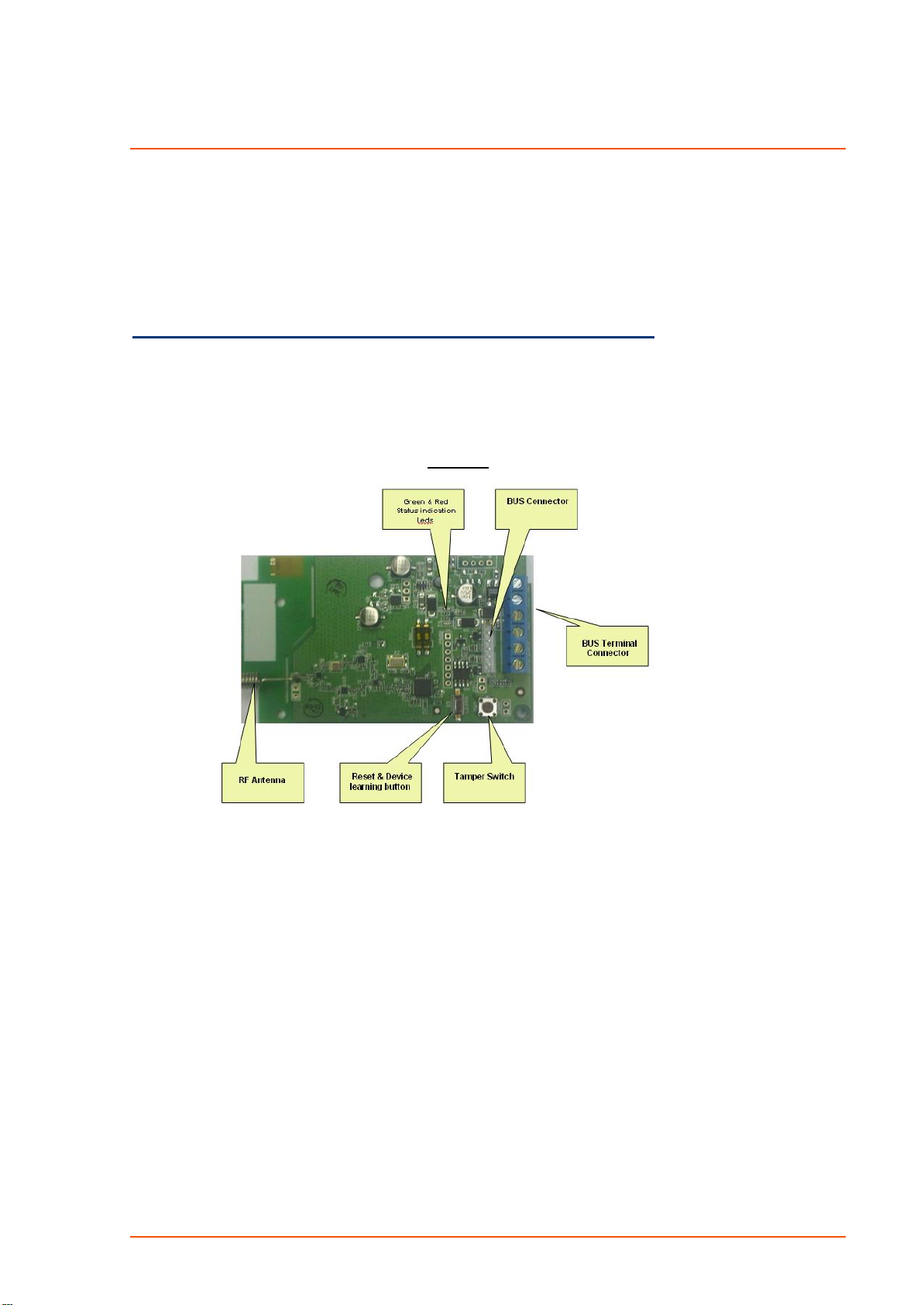
Figure
1

3
Siren Unit Description
Powered by non rechargeable battery Lithium 3.6V/14Ah or 12V DC or both ,in
this case the Battery use as backup.
Alarm signal will activate the Piezo Siren and the Power LED.
The Alarm can be reset by the user by using the Control Panel keypads in case
that itʹs not reset the time out 2min/15min according Jumper D selection –see
Table 1.
Arm/Disarm Indication by Beeps/ Flash (Jumper selection)‐See Table 1
Battery test generates every 4 hours.
Low Battery Indication by Beeps/Flash (Depends on Jumper Selection of B&C) ‐
See Table 1.
Tamper protected (Cover and Back tamper).
The signal transmitted to Transceiver: Synchronization, Acknowledge, Tamper
and
Low battery.
The Siren can be assigned to Area A or Area B by jumper selection –See Table 1
Setting the 2W-SIROUT-S for SIM Panels configuration
STEP 1: SIM TX/RX-PB-S – Learning & Operating Mode for
SIM Panels
It is most recommended to perform a factory default before the first
operation;
Press and Hold the reset push button (see button location in Figure 1).
Connect the bus cable while pressing and holding the reset button.
Continue to hold the reset button for several seconds till ledʹs will finish to flash red &
green alternately.
Wait until the ledʹs stops flashing and then remove your finger from the reset button.
Then slide the device into the socket.
For installation of External Transceiver Box and receiving indications from wireless Siren ‐
the
TX/RX-PB-S should be learned as well, please see and perform the following steps:
Remove the jumper.
Login to the runner programming mode and use the ZONE level to define the TX/RX-
PB-S
as wireless device (e.g. P122E 1‐16E options 1‐‐‐5‐‐‐ must be ON.
Enter to P164E (learn the radio device) 16E (e.g. Zone 16) and start the learning process.
While the Runner beeps for indicating learning process begin, press and release the
ʺLearn/resetʺ button for one second and notice the changes over the runner system
(Learning mode finish).
Make sure to close the tamper switch on the transceiver (in a case of external device
only) after the learning process ends.
Notice: zone (16) in the Runner will be used also by the wireless Sirens to display
an indication of (Low Battery, tamper, and supervision).
Note: The "learn/reset" push button used also for registered Siren inside the transceiver.
4
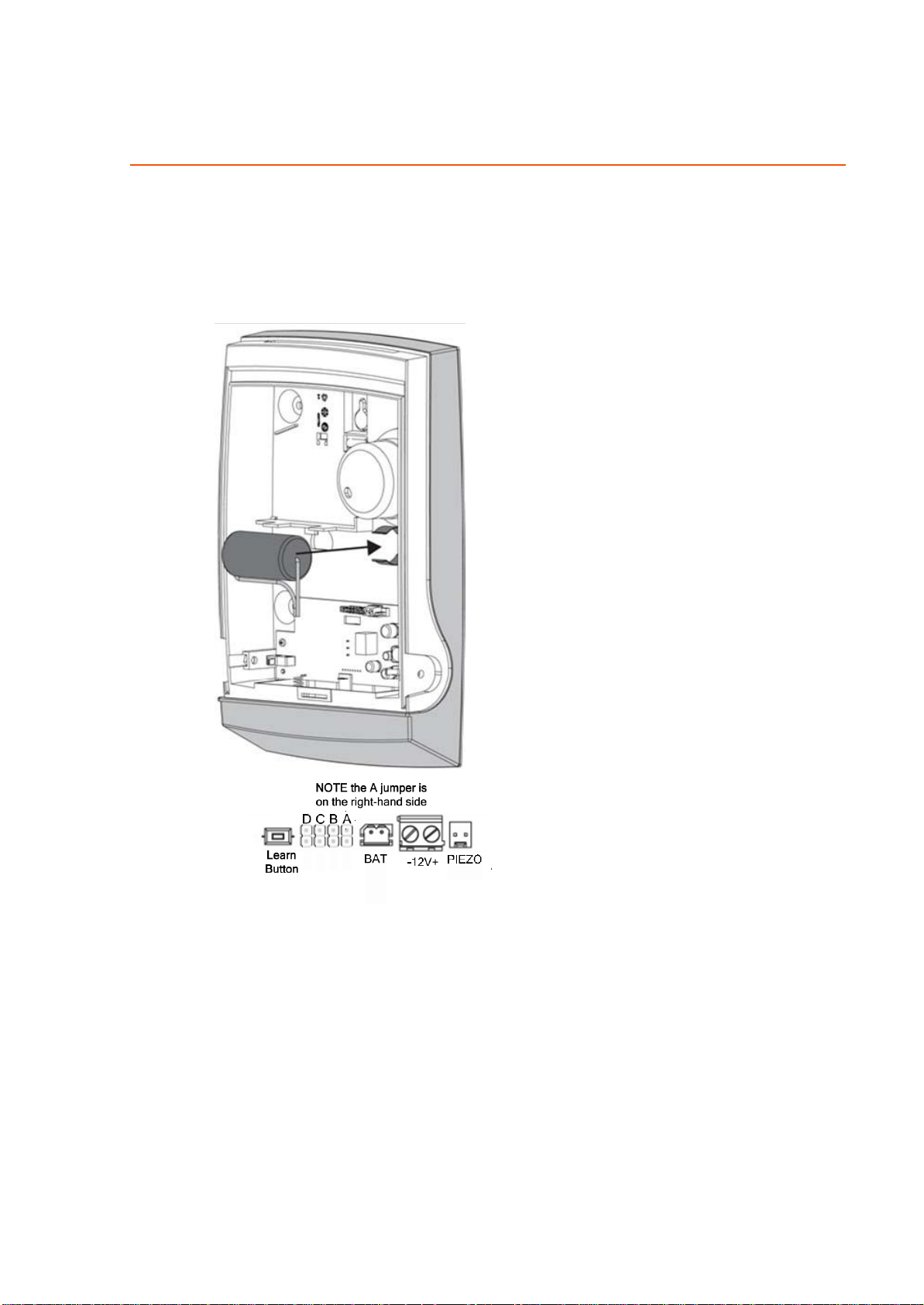
Physical Description
STEP 2: Setting the Siren Configuration Mode
Figure 2: Siren Description Diagram
The Siren unit can be powered by Lithium Battery 3.6V/14Ah or by external power
supply 12V/0.8A or both, in case of both the battery use as backup.
NOTE: refer to table 1 for Jumpers set-up on the next page
 Loading...