

Page 1

Document Number
10017C000
Version
3.9
Date
3/17/2015
Silvus Technologies, Inc.
10990 Wilshire Blvd, #1500
Los Angeles, CA 90024
StreamCaster MIMO Radio
User Manual
Page 2
StreamCaster MIMO Radio User Manual 3/17/15
Version
Date
Changes
1.0
September, 2012
Original
1.1
October 9, 2012
Minor Fixes
2.0
January 9, 2012
Updated for StreamScape 2.0
2.1
March 15, 2012
Updated Sensitivity Values. Added cable pinouts
2.2
May 23, 2013
Updated cable pinouts section
2.3
June 5, 2013
Added Tri-Color LED info
3.0
July 1, 2013
Updated for StreamScape 3.0
3.1
July 23, 2013
Minor Fixes
3.2
September 3, 2013
Added Link Characteristics
3.3
January 17, 2014
Updated Throughput in Tables 6 and 7
3.4
February 24, 2014
Updated through release SS3vb9.17
3.5
April 1, 2014
Updated to include SC3822
3.6
August 18, 2014
Updated for SS3.11.2.5
3.7
August 20, 2014
Added Safety Disclaimer
3.7.1
September 13, 2014
Updated FCC Clause
3.8
October 23, 2014
Added 10MHz data, added 3822 mechanicals, etc.
3.8.1
October 28, 2014
Added EXT PA related information
3.8.2
November 24, 2014
Added EXT PA Connector Diagram
3.9
March 17, 2015
Updated for SS3.11.3.13
Notice
Silvus Technologies reserves the right to make changes to its products or discontinue any of its products or offerings
without notice.
Silvus warrants the performance of its products to the specifications applicable at the time of sale in accordance with
Silvus’ standard warranty.
Revision History
10017C000 Silvus Technologies Confidential Page i
Copyright © 2013, Silvus Technologies
Page 3

StreamCaster MIMO Radio User Manual 3/17/15
1
Contents
1. General Safety Information ................................................................................................................... 5
1.1 Health & Safety .......................................................................................................................... 6
1.2 Maximum RF Power Density Limits .......................................................................................... 7
2. Introduction ........................................................................................................................................... 8
3. StreamCaster Network .......................................................................................................................... 8
4. Hardware Overview .............................................................................................................................. 9
4.1 StreamCaster Hardware Interface ............................................................................................... 9
SC3822: ...................................................................................................................................... 9
SC3500/SC3800: ...................................................................................................................... 10
SC3500/SC3800 with EXT Connector (PA Faceplate Option): ............................................... 11
4.1 Connector Pinouts ..................................................................................................................... 12
4.1.1 SC3822 Pinouts ........................................................................................................... 12
4.1.2 SC3500/SC3800 Pinouts ............................................................................................. 15
4.2 Mechanical and Operating Specifications ................................................................................ 19
4.2.1 SC3822 Enclosure Mechanical Drawing ..................................................................... 21
4.2.2 SC3500/SC3800 Phase II Enclosure Mounting Pattern .............................................. 22
4.2.3 SC3500/ SC3800 Phase III Enclosure Mounting Pattern ............................................ 23
4.3 SC3822 Specifications .............................................................................................................. 24
4.4 SC3500 Specifications .............................................................................................................. 25
4.5 SC3800 Specifications .............................................................................................................. 26
5. Web Interface ...................................................................................................................................... 27
5.1 Getting Started .......................................................................................................................... 27
5.1.1 Basic Configuration ..................................................................................................... 27
5.1.2 Advanced Configuration .............................................................................................. 29
5.1.3 Quality of Service (QoS) ............................................................................................. 34
5.1.4 Serial Port Setup .......................................................................................................... 35
5.1.5 Node Diagnostics ......................................................................................................... 36
5.1.6 BDA Support ............................................................................................................... 37
5.1.7 Build Information ........................................................................................................ 38
5.1.8 Security ........................................................................................................................ 39
5.1.9 Reset Password ............................................................................................................ 42
10017C000 Silvus Technologies Confidential Page
Page 4

StreamCaster MIMO Radio User Manual 3/17/15
2
5.2 StreamScape Network Manager ............................................................................................... 43
5.2.1 Network Topology ....................................................................................................... 43
5.2.2 Network-wide Setup and Multicast ............................................................................. 48
5.2.3 Per-Node Setup ............................................................................................................ 50
5.2.4 Map Overlay ................................................................................................................ 51
6. Wired Backbone .................................................................................................................................. 56
6.1 LAN Backbone ......................................................................................................................... 56
6.1.1 Implementation ............................................................................................................ 56
6.1.2 Use Case ...................................................................................................................... 56
6.2 WAN Backbone with Roaming ................................................................................................ 58
6.2.1 Implementation ............................................................................................................ 58
6.2.2 Use Case ...................................................................................................................... 58
7. Streaming Response ............................................................................................................................ 60
7.1 RSSI and Noise Floor Reporting .............................................................................................. 60
7.2 Temperature Reporting ............................................................................................................. 62
8. Setting up an Iperf Test ....................................................................................................................... 64
8.1 Required Equipment ................................................................................................................. 64
8.2 Running Iperf Test .................................................................................................................... 64
9. Precautions and Recommendations ..................................................................................................... 65
9.1 Saving the Radio Configuration ............................................................................................... 65
10. Troubleshooting .................................................................................................................................. 66
10.1 LED Issues ................................................................................................................................ 66
10.2 Intermittent Link ....................................................................................................................... 66
11. FCC Notice (SC3500-243541 Only) ................................................................................................... 67
10017C000 Silvus Technologies Confidential Page
Page 5

StreamCaster MIMO Radio User Manual 3/17/15
3
List of Figures
Figure 1 StreamCaster 3822 Ruggedized Enclosure................................................................................ 9
Figure 2 StreamCaster 3500/3800 Ruggedized Enclosure .................................................................... 10
Figure 3 StreamCaster 3500/3800 Ruggedized Enclosure .................................................................... 11
Figure 4 SC3822 Power/Serial/Ethernet Pinout Diagram (Cable Side) ............................................... 14
Figure 5 SC3500/SC3800 Power/Serial Pinout Diagram (Cable Side) for GPS (Top) and RS-232
(Bottom) ................................................................................................................................... 17
Figure 6 SC3500/SC3800 Ethernet Pinout Diagram (Cable Side) ........................................................ 18
Figure 7 SC3500/SC3800 EXT Pinout Diagram (Cable Side) .............................................................. 18
Figure 8 SC3822 Mechanical Drawing (top) and Mounting Pattern (bottom) ................................... 21
Figure 9 SC3500/SC3800 Phase II Enclosure Mounting Pattern for Back of Enclosure (top) and
Bottom of Enclosure (bottom) ............................................................................................... 22
Figure 10 SC3500/SC3800 Phase III Enclosure Mounting Pattern for Back of Enclosure (top) and
Bottom of Enclosure (bottom) ............................................................................................... 23
Figure 11 Basic Configuration Page ........................................................................................................ 27
Figure 12 Advanced Configuration Page ................................................................................................ 29
Figure 13 Quality of Service (QoS) Configuration Page ....................................................................... 34
Figure 14 Serial Port Setup Configuration Page (GPS Configuration) ............................................... 35
Figure 15 Node Diagnostics Configuration Page ................................................................................... 36
Figure 16 BDA (Bi-Directional Amplifier) Support Configuration Page ............................................ 37
Figure 17 Build Information .................................................................................................................... 38
Figure 18 Security (Encryption) .............................................................................................................. 39
Figure 19 Security (Admin) ...................................................................................................................... 39
Figure 20 Security (Upgrade)................................................................................................................... 40
Figure 21 Security (License)..................................................................................................................... 40
Figure 22 Security (Factory Reset) .......................................................................................................... 41
Figure 23 Security (Reset Password) ....................................................................................................... 42
Figure 24 Silvus StreamScapeNetwork Manager .................................................................................. 43
Figure 25 Example Network Topology ................................................................................................... 44
Figure 26 Routing Path ............................................................................................................................ 45
Figure 27 Custom Node Naming.............................................................................................................. 45
Figure 28 Individual Node Characteristics (Left), Link Characteristics (Right) ................................ 47
Figure 29 Network-wide Setup ................................................................................................................ 48
10017C000 Silvus Technologies Confidential Page
Page 6

StreamCaster MIMO Radio User Manual 3/17/15
4
Figure 30 Per-Node Setup ........................................................................................................................ 50
Figure 31 Map Overlay ............................................................................................................................ 51
Figure 32 Google Maps ............................................................................................................................. 52
Figure 33 Offline Map Image ................................................................................................................... 53
Figure 34 Placing Nodes on the Map ....................................................................................................... 55
Figure 35 LAN Backbone Example ......................................................................................................... 57
Figure 36 WAN Backbone Example........................................................................................................ 59
List of Tables
Table 1 Safe Working Distances ................................................................................................................ 6
Table 2 SC3822 Power/Ethernet/Serial Connector Pinout ................................................................... 12
Table 3 SC3822 Serial and GPS Pinout .................................................................................................. 12
Table 4 SC3822 USB/GPIO Connector Pinout ...................................................................................... 13
Table 5 SC3822 Extension Connector Pinout ......................................................................................... 13
Table 6 SC3500/SC3800 Power Connector Pinout ................................................................................ 15
Table 7 SC3500/SC3800 Ethernet Connector Pinout ............................................................................ 15
Table 8 SC3500/SC3800 EXT Connector Pinout ................................................................................... 16
Table 9 SC3500/SC3800 Serial and GPS Pinout .................................................................................... 16
Table 10 MCS vs. Sensitivity Chart (5MHz Bandwidth) ...................................................................... 32
Table 11 MCS vs. Sensitivity Chart (10MHz Bandwidth) .................................................................... 33
Table 12 MCS vs. Sensitivity Chart (20MHz Bandwidth) .................................................................... 33
Table 13 RSSI Reporting Format ............................................................................................................ 61
Table 14 Sample RSSI Report ................................................................................................................. 62
Table 15 Temperature Reporting Format .............................................................................................. 63
10017C000 Silvus Technologies Confidential Page
Page 7

StreamCaster MIMO Radio User Manual 3/17/15
5
1. General Safety Information
The information that follows, together with local site regulations, should be studied by
personnel concerned with the operation or maintenance of the equipment, to ensure
awareness of potential hazards.
Switch off supplies before removing covers or disconnecting any RF cables, and before
inspecting damaged cables or antennas.
Avoid standing in front of high gain antennas (such as a dish) and never look into the open end
of a waveguide or cable where strong RF power may be present.
Users are strongly recommended to return any equipment that requires RF servicing to Silvus
Technologies.
CAUTION: This system contains MOS devices. Electro-Static Discharge (ESD) precautions
should be employed to prevent accidental damage.
10017C000 Silvus Technologies Confidential Page
Page 8
StreamCaster MIMO Radio User Manual 3/17/15
6
Antenna
Transmitter Power
Type
Gain (dBi)
Gain Ratio (GR)
1W
2W
4W
10W
30W
Omni
3 2 0.4
0.6
0.8
1.3
2.2
Sector
20
100
2.9 4 5.6 9 15.5
Parabolic Dish
35
3162
16
22.5
32
50
87 Minimum Safe Distance (Meters)
1.1 Health & Safety
Exposure to Non-Ionizing (RF) Radiation/Safe Working Distances
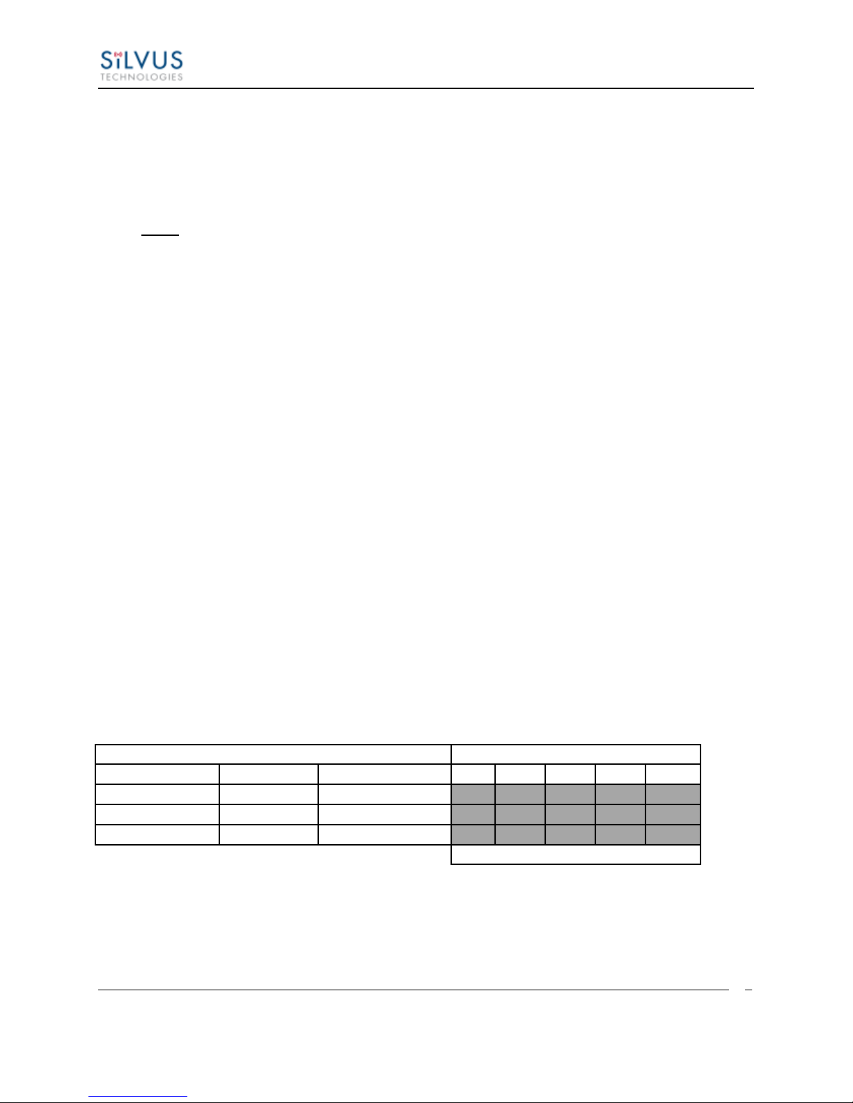
The safe working distance from a transmitting antenna may be calculated from the relationship:
D =
In which D = safe working distance (meters)
PT = transmitter or combiner power output (watts)
GR = antenna gain ratio = anti log (gain dBi ÷10)
w = power density (watts/square meter)
The RF power density value is determined by reference to safety guidelines for exposure of the
human body to non-ionizing radiation. It is important to note that the guidelines adopted differ
throughout the world and are from time-to-time re-issued with revised guidelines. For Silvus use,
a maximum power density limit of 1w/m² is to be applied when calculating minimum safe
working distances.
Important Note: It must be remembered that any transmitting equipment radiating power at
frequencies of 100 KHz and higher, has the potential to produce thermal and a-thermal effects
upon the human body.
To be safe:
a) Operators should not stand or walk in front of any high gain antenna such as dish antennas,
nor should they allow anyone else to do so.
b) Operators should not operate any RF transmitter or power amplifier with any of its covers
removed, nor should they allow anyone else to do so.
Table 1 Safe Working Distances
10017C000 Silvus Technologies Confidential Page
Page 9

StreamCaster MIMO Radio User Manual 3/17/15
7
1.2 Maximum RF Power Density Limits
The RF Radiation Power Density limit figure recommended by Silvus is based upon guideline
levels published in:
a. IEEE standard C95.1 1999 - IEEE Standard for Safety Levels with respect to Human Exposure
to Radio Frequency Electromagnetic Fields, 3 kHz to 300 GHz.
b. Guidelines for Limiting Exposure to Time-varying Electric, Magnetic & Electromagnetic
Fields (up to 300 GHz) published in 1998 by the Secretariat of the International Commission on
Non-Ionizing Radiation Protection (ICNIRP).
Both documents define guideline RF power density limits for "Controlled" and "Uncontrolled"
environments. An uncontrolled environment is defined as one in which the person subjected to
the RF radiation may be unaware of and has no control over the radiation energy received. The
uncontrolled environment conditions can arise, even in the best regulated operations and for this
reason the limits defined for the uncontrolled environment have been assumed for the RF Central
recommended limit.
Documents a) and b) also show the RF power density guidelines to be frequency dependent.
Different power density / frequency characteristics are presented in the two documents. To avoid
complexity and to avoid areas of uncertainty, Silvus recommends the use of a single power
density limit across the frequency range 100 kHz to 300 GHz. The 1w/m² power density limit we
recommend satisfies the most stringent of the guidelines published to date.
Footnote: The IICNIRP document may be freely downloaded from the internet at
www.icnirp.de/documents/emfgdl.pdf (PDF file).
10017C000 Silvus Technologies Confidential Page
Page 10

StreamCaster MIMO Radio User Manual 3/17/15
8
2. Introduction
The StreamCaster family of MIMO radios was designed with operator ease of use in mind. Each
radio is capable of operating in a multitude of configurations that are accessed via simple web
pages within the radio. Settings such as transmit power, frequency, channel bandwidth, link
adaptation and range control can be accessed by simply using a web browser to log into any
radio within the network. This quick start user guide contains all essential information for the
user to configure the StreamCaster radio and to also run an iperf network test.
3. StreamCaster Network
Each StreamCaster MIMO radio has a fixed static IP address in the 172.20.xx.yy network. The
radio operates as a network switch; the user equipment does not need to be on the same subnet as
the radio during operation. It is possible to setup a secondary IP address on the radio if the user
finds this feature convenient. Setting up a secondary IP address is useful if the user wishes to
access the radio’s web interface in their network.
10017C000 Silvus Technologies Confidential Page
Page 11
StreamCaster MIMO Radio User Manual 3/17/15
9
1 2 3
4
2 1 3
4
4. Hardware Overview
4.1 StreamCaster Hardware Interface
SC3822:
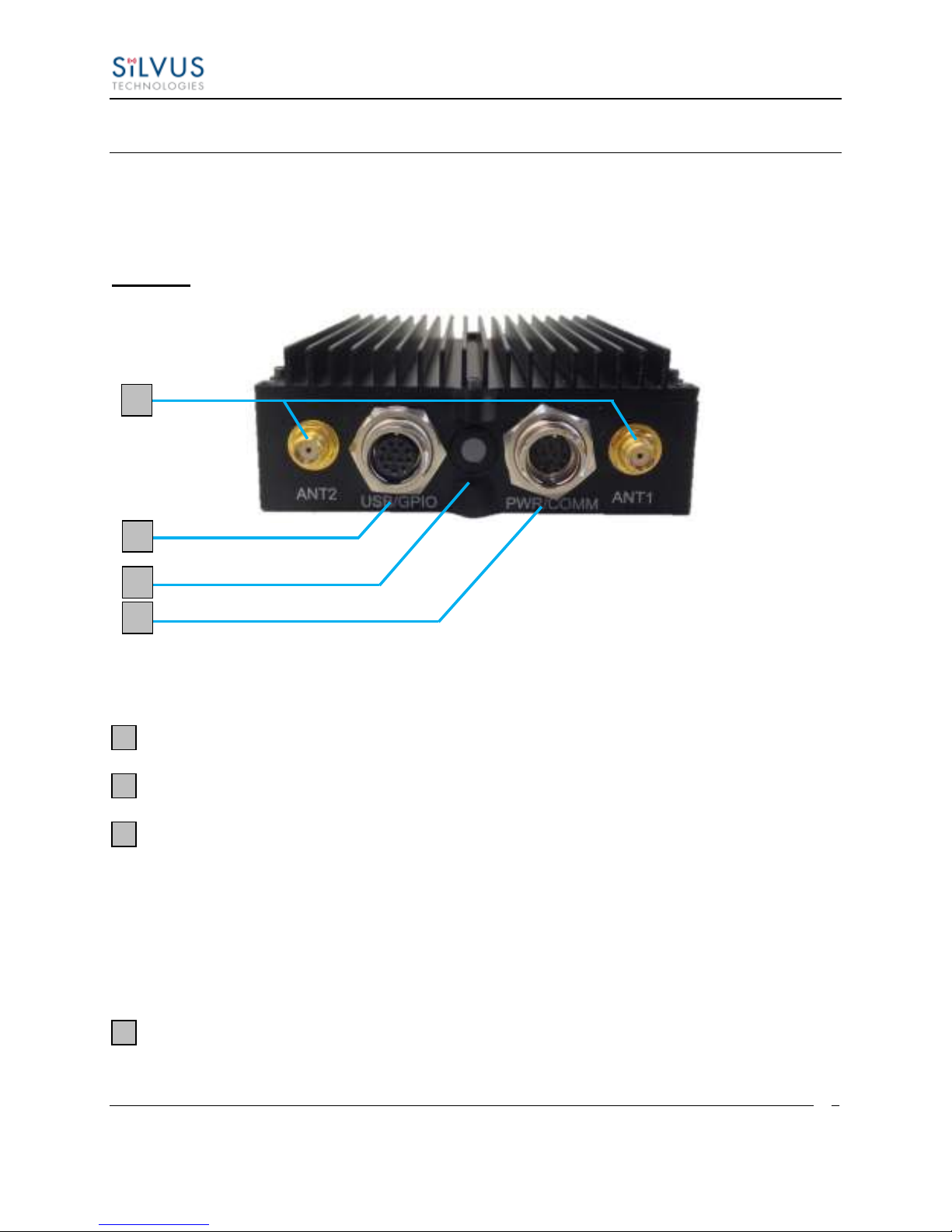
Figure 1 StreamCaster 3822 Ruggedized Enclosure
RF channels 1-2 connectors [SMA Female]
USB/GPIO connector [Hirose LF10WBRB-12SD]
Tri-Color Status LED (See Section 10.1 for Troubleshooting Information)
Red – Radio is in the process of booting up
Orange – Radio is fully booted but not wirelessly connected to any other radio
Green – Radio is wirelessly connected to at least one other radio
Flashing Red – Radio has recovered from a bad state and has reverted to factory
default settings.
Power (9-32 VDC), Ethernet, and Serial Port connector [Hirose LF10WBRB-12PD]
10017C000 Silvus Technologies Confidential Page
Page 12
StreamCaster MIMO Radio User Manual 3/17/15
10
1
2
3
4
5
2
3
4
1
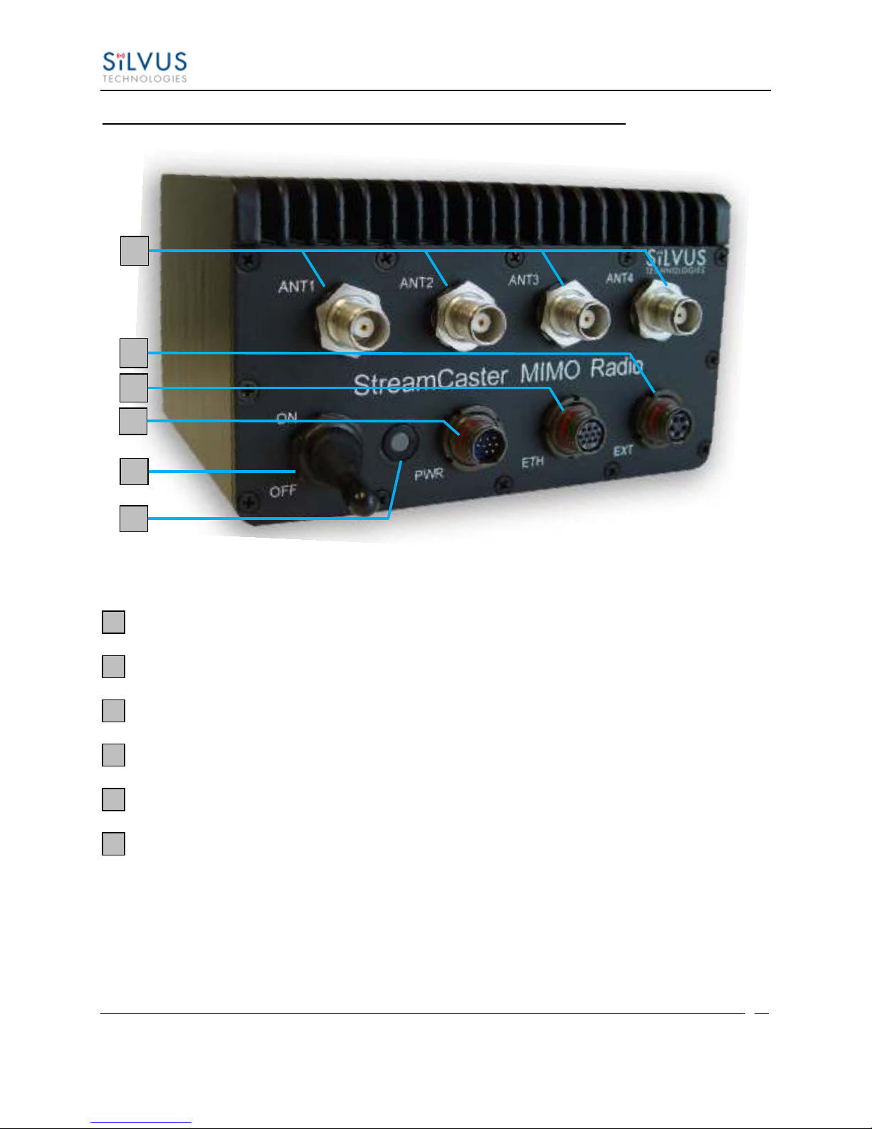
SC3500/SC3800:
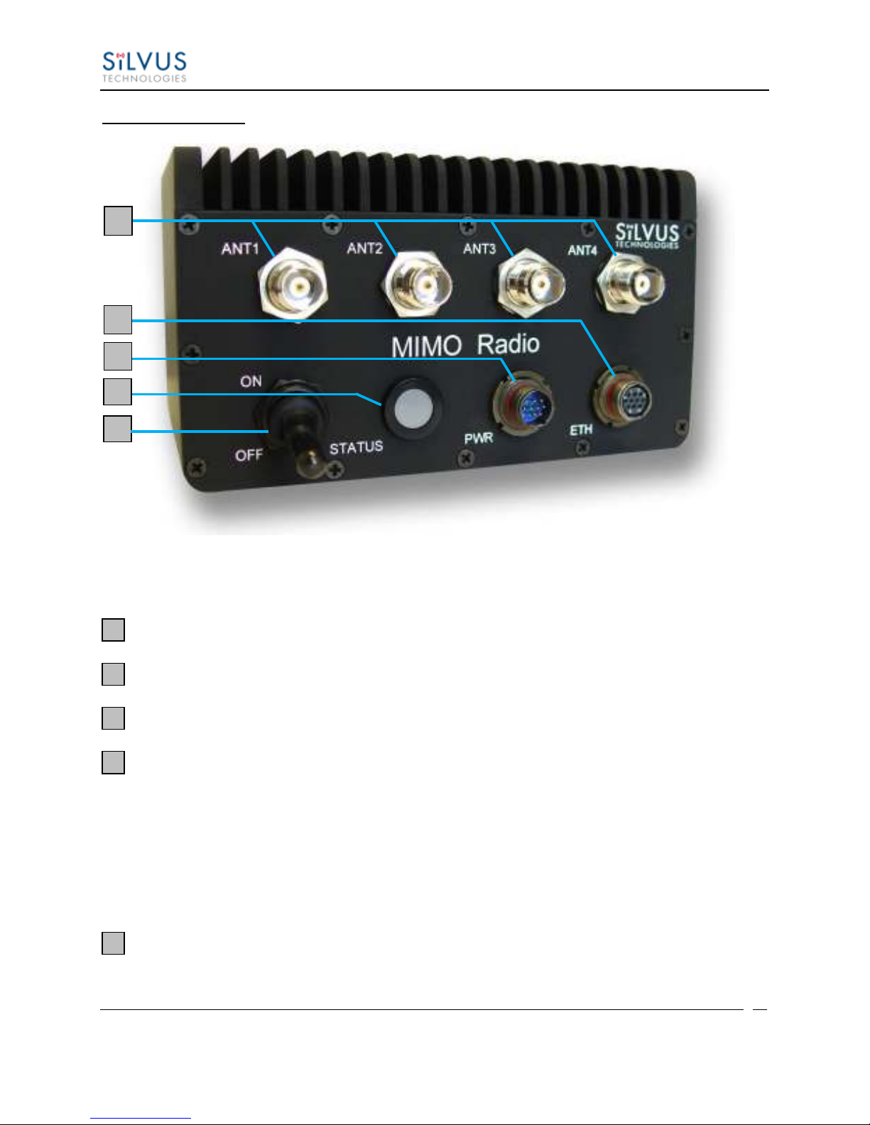
Figure 2 StreamCaster 3500/3800 Ruggedized Enclosure
RF channels 1-4 connectors [TNC Female]
Ethernet connector [Mighty-Mouse 801-010-07NF7-10SA]
Power (9-20 VDC) and Serial Port connector [Mighty-Mouse 801-010-07NF7-10PA]
Tri-Color Status LED (See Section 10.1 for Troubleshooting Information)
Red – Radio is in the process of booting up
Orange – Radio is fully booted but not wirelessly connected to any other radio
Green – Radio is wirelessly connected to at least one other radio
Flashing Red – Radio has recovered from a bad state and has reverted to factory
default settings
Power Switch
10017C000 Silvus Technologies Confidential Page
Page 13
StreamCaster MIMO Radio User Manual 3/17/15
11
1
2
3 4 5
6
2
3
4
1
6
5
SC3500/SC3800 with EXT Connector (PA Faceplate Option):
Figure 3 StreamCaster 3500/3800 Ruggedized Enclosure
RF channels 1-4 connectors [TNC Female]
EXT PA Connector [Mighty-Mouse 801-010-07NF7-25SA]
Ethernet connector [Mighty-Mouse 801-010-07NF7-10SA]
Power (9-20 VDC) and Serial Port connector [Mighty-Mouse 801-010-07NF7-10PA]
Power Switch
Tri-Color Status LED (See Section 10.1 for Troubleshooting Information)
Red – Radio is in the process of booting up
Orange – Radio is fully booted but not wirelessly connected to any other radio
Green – Radio is wirelessly connected to at least one other radio
Flashing Red – Radio has recovered from a bad state and has reverted to factory
default settings
10017C000 Silvus Technologies Confidential Page
Page 14

StreamCaster MIMO Radio User Manual 3/17/15
12
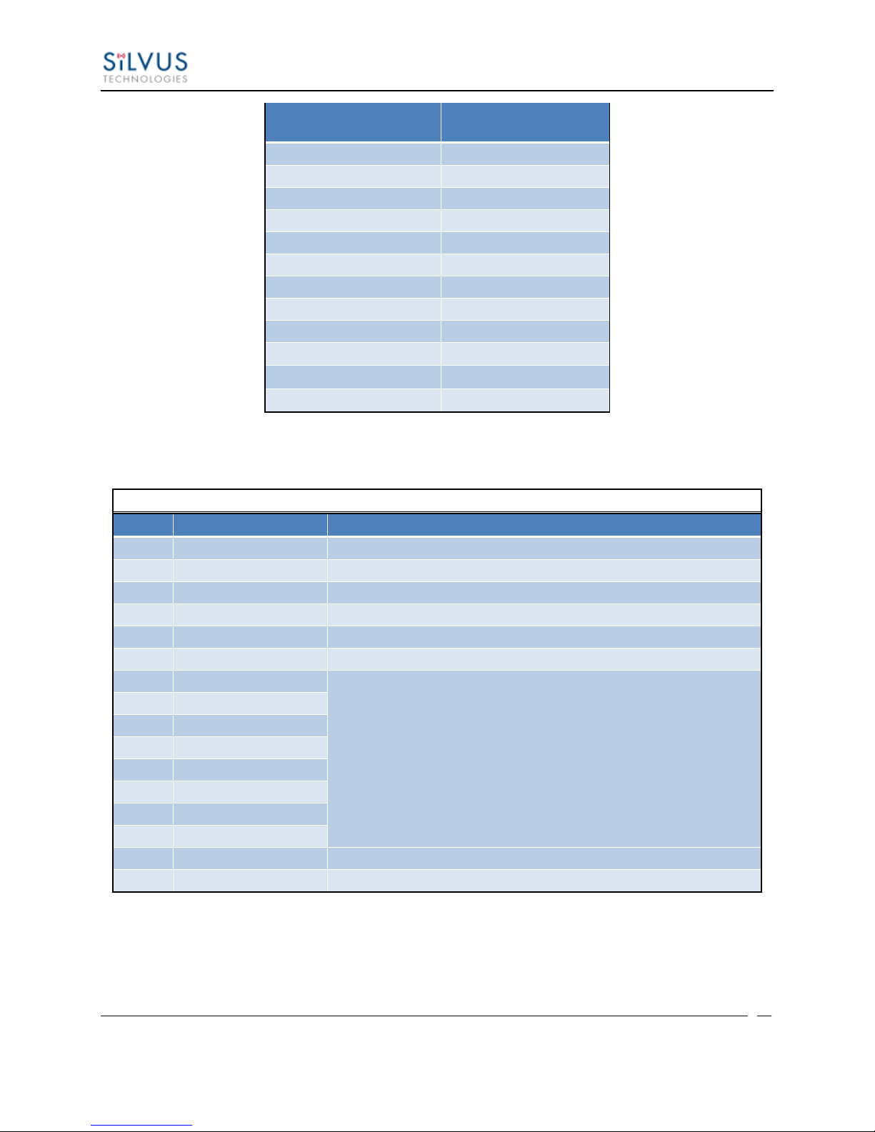
SC3822 Power/Ethernet/Serial Connector Pinout
Enclosure PWR/COMM
(LF10WBRB-12PD)
Signal
Switchcraft Pinout
(EN3C2F16X)
1
3.3V OUT
NC 2 GND IN
2
3
GND IN
2
4
VCC IN 1 5
VCC IN
1
6
100-Base T ETH0 M2N
NC
7
100-Base T ETH0 M2P
NC
8
100-Base T ETH0 M1P
NC
9
RS232_RXD
NC
10
RS232_TXD
NC
11
RS232_GND
NC
12
100-Base T ETH0 M1N
NC
SC3822 RS-232 and PS/2 (GPS) Pinout
RS-232
PS/2 (GPS)
Signal
Switchcraft Pinout
3 4 TxD 2 2 5 RxD
1
7
NC
RTS 4 NC
2
3.3V Out
6
8
NC
CTS
5
5 1 Ground
3
SC3822 USB/GPIO Connector Pinout
4.1 Connector Pinouts
4.1.1 SC3822 Pinouts
Table 2 SC3822 Power/Ethernet/Serial Connector Pinout
Table 3 SC3822 Serial and GPS Pinout
10017C000 Silvus Technologies Confidential Page
Page 15
StreamCaster MIMO Radio User Manual 3/17/15
13
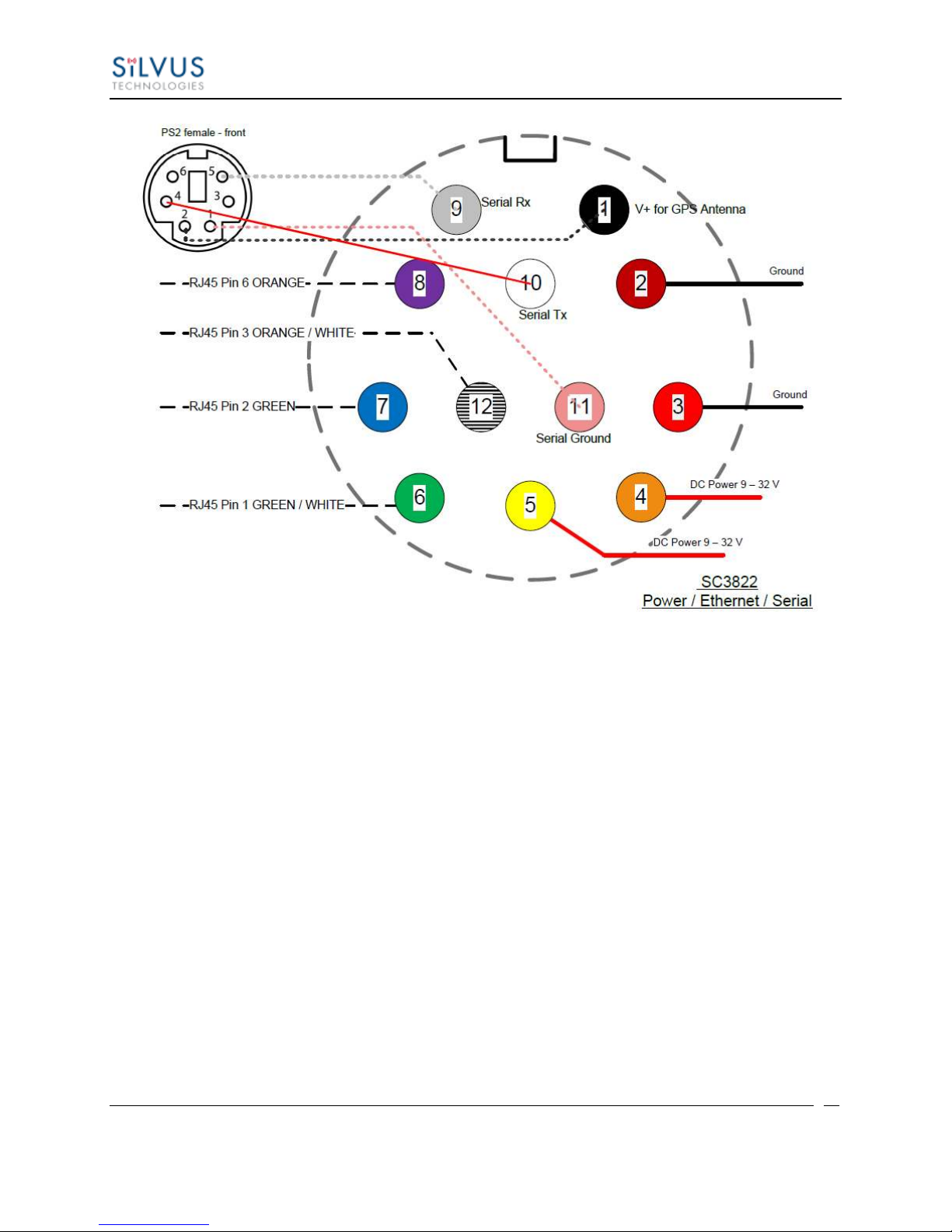
Enclosure USP/GPIO
(LF10WBRB-12PD)
Signal
1
USB_GND
2
USB_D-
3
USB_5V
4
NC
5
GPIO1 (PA Enable 3.3V)
6
GPIO2
7
GPIO3
8
3.3V
9
GND
10
USB_Sense
11
USB_D+
12
GPIO4
SC3822 Extension Connector Pinout
Pin #
Signal
Notes
1-6
VCC_IN
9V - 36V. These pins are directly wired to the VCC_IN on FPC 1.
7-10
GPIO1 – GPIO4
These GPIOs are directly wired to the GPIOs on FPC connector 2.
11-19
Reserved for Testing
Do Not Connect
20
CPU Reset (3.3V)
Wired to PS_SRST_EXT signal on FPC 1
21-54
Reserved for Testing
Do Not Connect
55
GND
56
ETH1_MX4N
Second Gigabit Ethernet Interface
57
ETH1_MX4P
58
ETH1_MX3N
59
ETH1_MX3P
60
ETH1_MX2N
61
ETH1_MX2P
62
ETH1_MX1N
63
ETH1_MX1P
64
GND
65-68
Reserved for Testing
Do Not Connect
Table 4 SC3822 USB/GPIO Connector Pinout
Table 5 SC3822 Extension Connector Pinout
10017C000 Silvus Technologies Confidential Page
Page 16
StreamCaster MIMO Radio User Manual 3/17/15
14
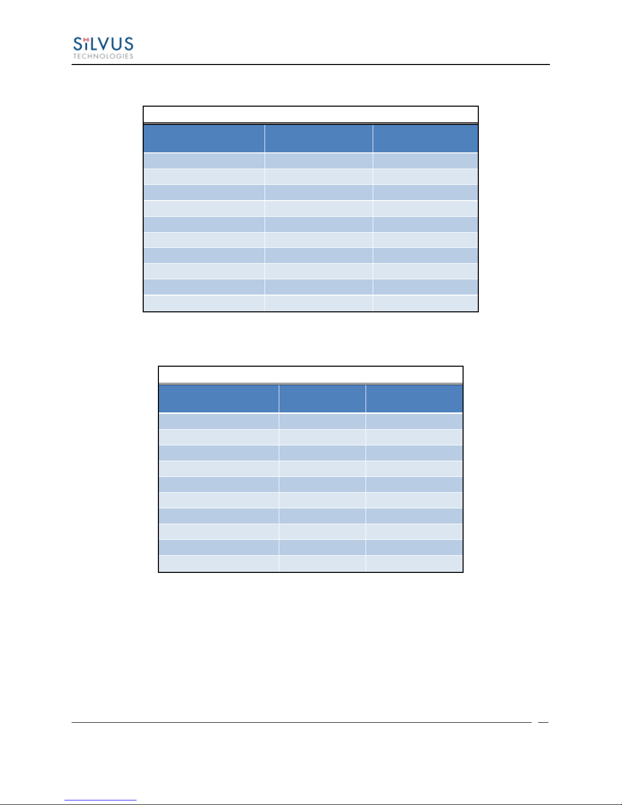
Figure 4 SC3822 Power/Serial/Ethernet Pinout Diagram (Cable Side)
10017C000 Silvus Technologies Confidential Page
Page 17
StreamCaster MIMO Radio User Manual 3/17/15
15
SC3500/3800 Power Connector Pinout
Enclosure Pinout
(801-010-07NF7-10PA)
Signal
Switchcraft Pinout
(EN3C2F16X)
1
12V Power Return
2
2
12V Power Return
2
3
12V Power
1
4
12V Power
1 5 TxD
For Serial Comm.
6
RxD
For Serial Comm.
7
RTS
For Serial Comm.
8
CTS
For Serial Comm.
9
Ground
For Serial Comm.
10
3.3VDC Out
3.3VDC for GPS
SC3500/3800 Ethernet Connector Pinout
Enclosure Pinout
(801-010-07NF7-10SA)
Signal
RJ45 Pinout
1
WHT/BLU 5 2
WHT/BRN
7
3
BRN 8 4
ORG 2 5
WHT/GRN
3
6
WHT/ORG 1 7
BLU 4 8
GRN
6
9
NC
NC
10
NC
NC
4.1.2 SC3500/SC3800 Pinouts
Table 6 SC3500/SC3800 Power Connector Pinout
Table 7 SC3500/SC3800 Ethernet Connector Pinout
10017C000 Silvus Technologies Confidential Page
Page 18
StreamCaster MIMO Radio User Manual 3/17/15
16
SC3500/3800 EXT Connector Pinout (PA Faceplate Option Only)
Enclosure Pinout
(801-010-07NF7-25SA)
Signal
1
PA On (+3.3V)
2
Ground
3
LED1 (Black)
4
LED2 (Green)
5
LED3 (Red)
SC3500/3800 RS-232 and PS/2 (GPS) Pinout
RS-232
PS/2 (GPS)
Signal
Switchcraft Pinout
3 4 TxD
2
2 5 RxD
1
7
NC
RTS 4 NC
2
VCC (3.3V)
6
8
NC
CTS
5
5 1 Ground
3
NA
NA
LED Ground
NA
NA
NA
Green
NA
NA
NA
Red
NA
Table 8 SC3500/SC3800 EXT Connector Pinout
Table 9 SC3500/SC3800 Serial and GPS Pinout
10017C000 Silvus Technologies Confidential Page
Page 19
StreamCaster MIMO Radio User Manual 3/17/15
17
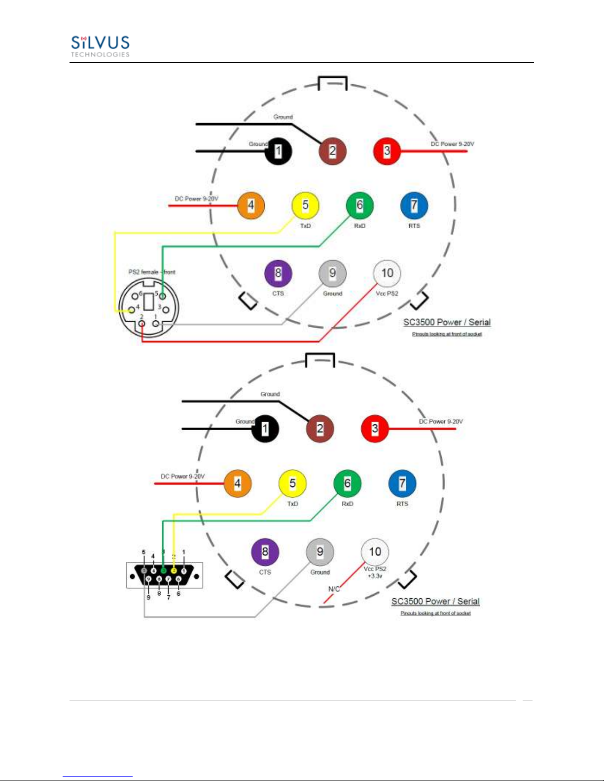
Figure 5 SC3500/SC3800 Power/Serial Pinout Diagram (Cable Side) for GPS (Top) and RS-232 (Bottom)
10017C000 Silvus Technologies Confidential Page
Page 20
StreamCaster MIMO Radio User Manual 3/17/15
18
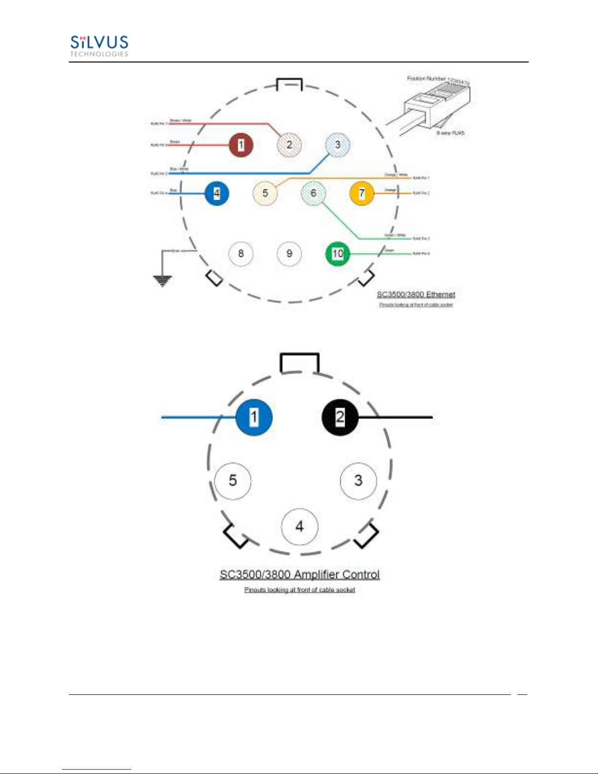
Figure 6 SC3500/SC3800 Ethernet Pinout Diagram (Cable Side)
Figure 7 SC3500/SC3800 EXT Pinout Diagram (Cable Side)
10017C000 Silvus Technologies Confidential Page
Page 21
StreamCaster MIMO Radio User Manual 3/17/15
19
Environmental
Standard Temperature
Extended Temperature
Operating Temp.
-40° - +55° C
-40° - +65° C
IP Rating
(Ingress Protection)
IP-67 (Dust / Immersion in water up to 1m)*
*Must have all connectors mated and use IP67 or better cables/antennas
Mechanical – Chassis
Standard
Extended Temperature
Dimensions
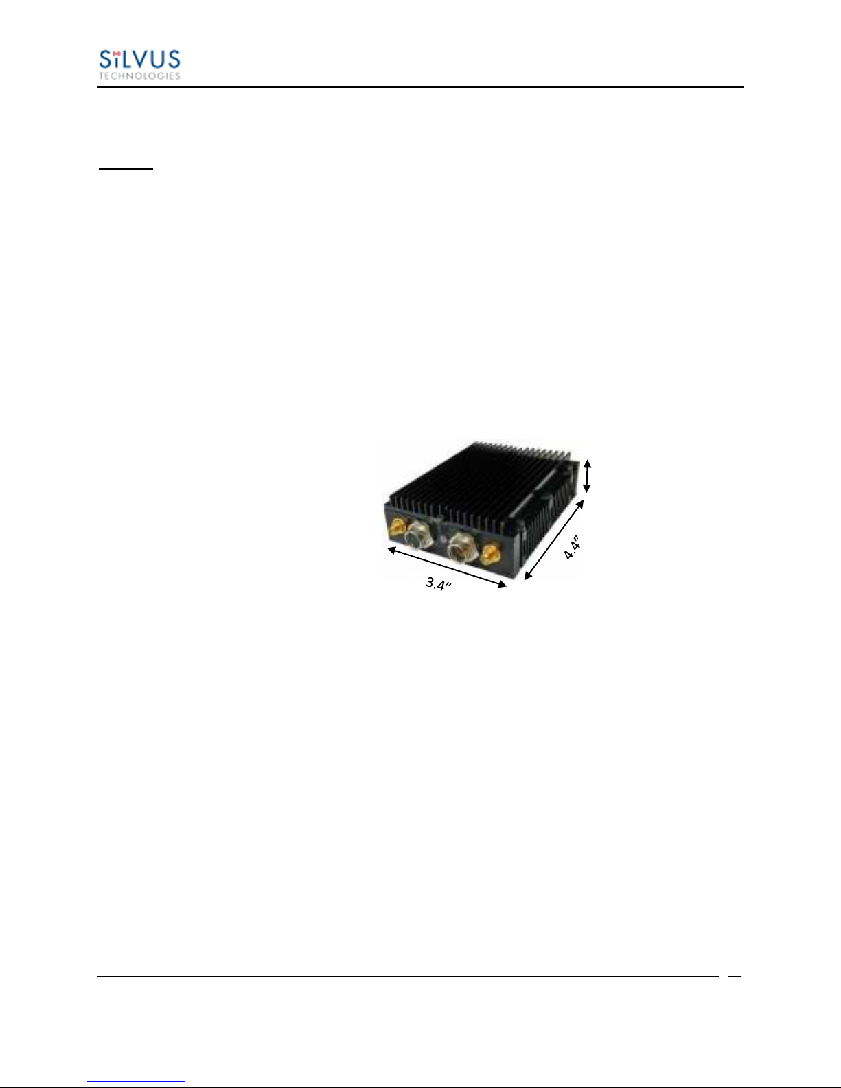
4.4” x 3.4” x 1.3”
4.4” x 3.4” x 2.0”
Weight
1.0 Pounds
1.2 Pounds
Color
a. Black anodized
b. FED-STD-595B-34094 (green 383)
Mounting
4-hole mounting patterns (Through-hole)
Connectors
RF
SMA (f) (2 each)
Data / Control
Ethernet (Gigabit for OEM, 100 Base-T for Enclosed), RS232, USB
Power
Hirose LF Series Circular Connector (Front Panel)
Samtec QSH (Expansion)
Controls and Indicators
Status Indicator
Tri-Color LED
Power Requirements
Voltage
9 – 32 VDC
Consumption
6W – 16W (Duty Cycle and Frequency Dependent)
Mechanical – OEM Board Stack
Dimensions
3.3” x 2.9” x 0.5” L x W x H
Weight
3 oz
RF Connector
SMP (m)
*Standard Temperature enclosure shown.
Exteded Tep has height of ”.
.”
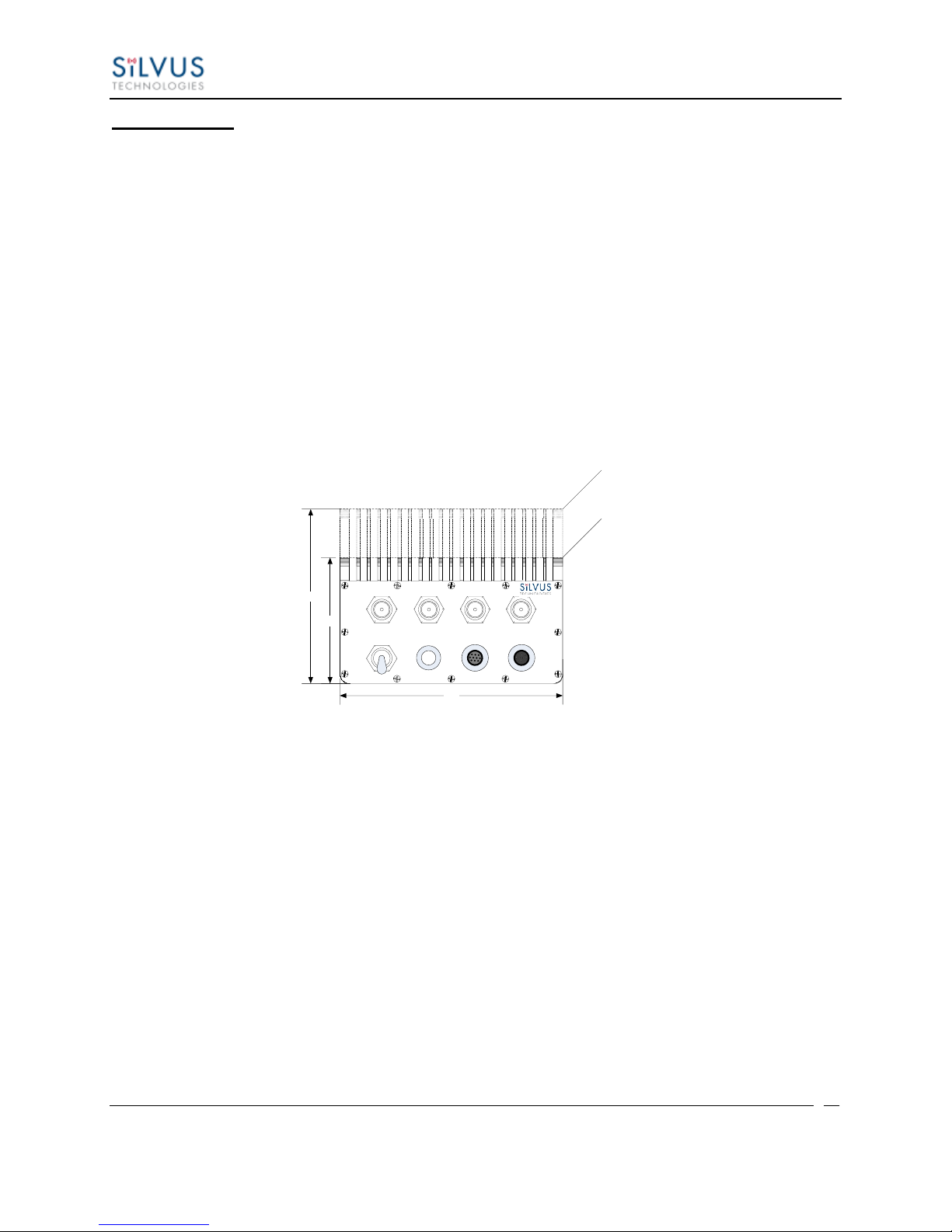
4.2 Mechanical and Operating Specifications
SC3822:
10017C000 Silvus Technologies Confidential Page
Page 22
StreamCaster MIMO Radio User Manual 3/17/15
20
Environmental
Standard
Extended Temperature
Operating Temp.
-40° - +55° C
-40° - +65° C
IP Rating
IP-67 (Dust / Immersion in water up to 1m)*
(Ingress Protection)
*Must have all connectors mated and use IP67 or better cables/antennas
Mechanical – Chassis
Standard
Extended Temperature
Dimensions
3.25” x 5.75” x 4”
4.5” x 5.75” x 4”
Weight
3.7 Pounds
4.0 Pounds
Color
c. FED-STD-595B-34094 (green 383)
d. Black anodized
e. CARC (Chemical Agent Resistant Coating)
Mounting
4-hole mounting patterns (non-penetrating)
located on both rear and bottom sides
Connectors
RF
TNC (f) (4 each)
Data / Control
Ethernet cable, Mighty-Mouse 801 Heavy-Duty, Double-Start 10
Power
Mighty-Mouse 801 Heavy-Duty, Double-Start 10 conductor (m)
(RS232 / GPS Support)
Controls and Indicators
Power
On / Off Toggle with detent
Status Indicator
Tri-Color LED
Power Requirements
Voltage
9 – 20 VDC
Consumption
12W – 22.5W (Duty Cycle and Frequency Dependent)
Mechanical – OEM Board Stack
Dimensions
1.9” x 5.25” x 2.9” H x L x W
Weight
8 oz
RF Connector
SMP (m)
Data Connector
Harwin M80 8-pin (m), (RS232/GPS optional)
Power Connector
Harwin M80 8-pin
5.75
4.50
3.25
Extended Temperature Variant
Standard Temperature Variant
ANT1 ANT4ANT3ANT2
STATUS PWROFF ETH
ON
SC3500/SC3800:
10017C000 Silvus Technologies Confidential Page
Page 23
StreamCaster MIMO Radio User Manual 3/17/15
21
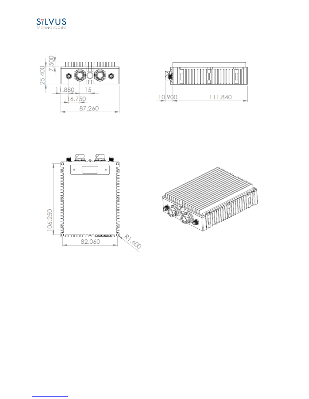
4.2.1 SC3822 Enclosure Mechanical Drawing
Figure 8 SC3822 Mechanical Drawing (top) and Mounting Pattern (bottom)
10017C000 Silvus Technologies Confidential Page
Page 24
StreamCaster MIMO Radio User Manual 3/17/15
22
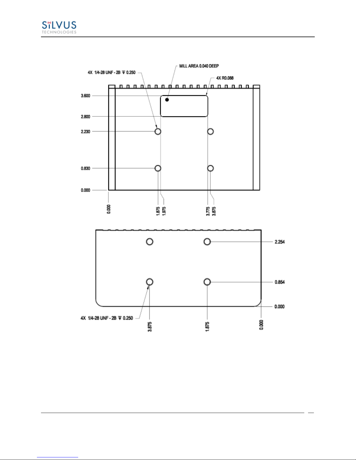
4.2.2 SC3500/SC3800 Phase II Enclosure Mounting Pattern
Figure 9 SC3500/SC3800 Phase II Enclosure Mounting Pattern for Back of Enclosure (top) and Bottom of Enclosure
(bottom)
10017C000 Silvus Technologies Confidential Page
Page 25
StreamCaster MIMO Radio User Manual 3/17/15
23
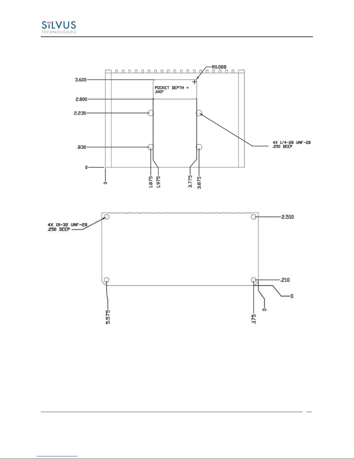
4.2.3 SC3500/ SC3800 Phase III Enclosure Mounting Pattern
Figure 10 SC3500/SC3800 Phase III Enclosure Mounting Pattern for Back of Enclosure (top) and Bottom of Enclosure
10017C000 Silvus Technologies Confidential Page
(bottom)
Page 26

StreamCaster MIMO Radio User Manual 3/17/15
24
General
Waveform
Mobile Networked MIMO (MN-MIMO™)
Modulation
BPSK, QPSK, 16-QAM, 64-QAM
Channel Bandwidth
5, 10 & 20 MHz (1.25*, 2.5*)
Encryption
DES Standard, AES 128/256 Optional (FIPS 140-2)
Frequency Stability
1 PPM over temp -40° - +85° C
Tuning Step Size
1 KHz
Data Rates
85 Mbps UDP & 70 Mbps TCP
MAC Protocols
(Medium Access Control)
CSMA, TDMA, TPMA
Error Correction
1/2, 2/3, 3/4, 5/6
Antenna Processing
Spatial Multiplexing, Space-Time Coding,
RX Eigen Beam Forming
No. of Spatial Streams
1-2
No. of Antennas
Total Power Output
2
10mW – 500mW (variable)
Performance
Latency
7 ms average
Sensitivity
Varies with MCS index
Maximum = -99 dBm (5MHz BW, MCS0)
Frequency Band Specifics
Please note, this table reflects standard frequency bands available, additional bands are frequently added as demands
dictate. If your band of interest is not listed, please contact your sales person. (All bands listed in MHz)
Low Band
High Band
UHF
400-450 *
C-1 Band
4400-4700
ISM 900
902-928 *
C-2 Band
4700-5000
L Band
1350-1390
C-3 Band
5727-5852
Broadcast A
1980-2200
UNII-1 Band
5150-5250
Broadcast B
2025-2110
Federal ‘S’
2200-2500
ISM2400
2400-2500
4.3 SC3822 Specifications
10017C000 Silvus Technologies Confidential Page
Page 27

StreamCaster MIMO Radio User Manual 3/17/15
25
General
Radio Type
MIMO Coded-OFDM
Subcarrier Modulation
BPSK, QPSK, 16-QAM, 64-QAM
Channel Bandwidth
5, 10 & 20 MHz
Encryption
DES Standard, AES 128/256 Optional
Frequency Stability
1 PPM over temp -40° - +85° C
Tuning Step Size
1 KHz
Data Rates
75 Mbps UDP & 60 Mbps TCP
MAC Protocols
(Medium Access Control)
Error Correction
CSMA, TDMA, TPMA
1/2, 2/3, 3/4, 5/6
Antenna Processing
Spatial Multiplexing, Space-Time Coding,
Eigen Beam Forming
No. of Spatial Streams
1-4
No. of Antennas
4
Total Power Output
10mW – 1W (variable)
Performance
Latency
7 ms average
Sensitivity
Varies with MCS index
Maximum = -102 dBm (5 MHz BW, MCS 0)
Frequency Band Specifics
S Band
C Band
Frequency Code ‘243541’
2.385 – 2.490 GHz
4.9425 – 5.875 GHz
Frequency Code ‘243578’
2.427 – 2.447 GHz
5.745 – 5.830 GHz
4.4 SC3500 Specifications
10017C000 Silvus Technologies Confidential Page
Page 28

StreamCaster MIMO Radio User Manual 3/17/15
26
General
Radio Type
MIMO Coded-OFDM
Subcarrier Modulation
BPSK, QPSK, 16-QAM, 64-QAM
Channel Bandwidth
5, 10 & 20 MHz (1.25*, 2.5*)
Encryption
DES Standard, AES 128/256 Optional
Frequency Stability
1 PPM over temp -40° - +85° C
Tuning Step Size
1 KHz
Data Rates
75 Mbps UDP & 60 Mbps TCP
MAC Protocols
(Medium Access Control)
CSMA, TDMA, TPMA
Error Correction
1/2, 2/3, 3/4, 5/6
Antenna Processing
Spatial Multiplexing, Space-Time Coding,
RX Eigen Beam Forming
No. of Spatial Streams
1-4
No. of Antennas
Total Power Output
4
10 mW – 1 W (variable)
Performance
Latency
7 ms average
Sensitivity
Varies with MCS index
Maximum = -102 dBm (5MHz BW, MCS 0)
Frequency Band Specifics
Please note, this table reflects standard frequency bands available, additional bands are frequently added as demands
dictate. If your band of interest is not listed, please contact your sales person. (All bands listed in MHz)
Low Band
High Band
UHF
400-450 *
C-1 Band
4400-4700
ISM 900
902-928 *
C-2 Band
4700-5000
L Band
1350-1390
C-3 Band
5727-5852
Broadcast A
1980-2200
UNII-1 Band
5150-5250
Broadcast B
2025-2110
Federal ‘S’
2200-2500
Footnote: (*) in development
4.5 SC3800 Specifications
10017C000 Silvus Technologies Confidential Page
Page 29
StreamCaster MIMO Radio User Manual 3/17/15
27
5. Web Interface
5.1 Getting Started
Connect a laptop to the StreamCaster radio using the supplied Ethernet cable and turn on the
radio. Users can type “ping <IPaddress>” in order to determine whether the radio is fully booted.
A web configuration will then be available by typing the radio IP address in a web browser.
Please ensure that your laptop is on the same subnet as the radio (172.20.xx.xx by default). Users
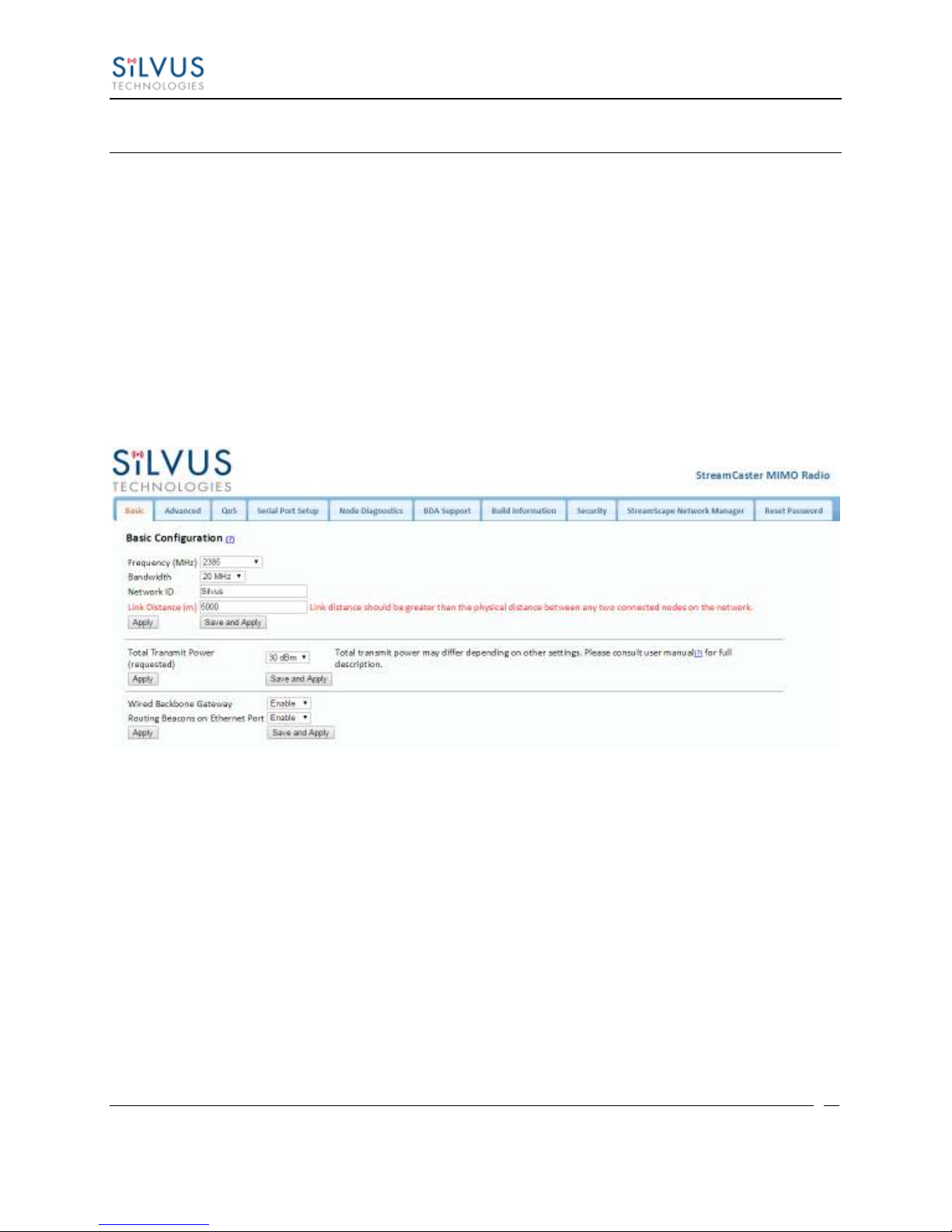
will be directed to the Basic Configuration page. (See Figure 11)
5.1.1 Basic Configuration
Figure 11 Basic Configuration Page
This page is used to set basic configurations. A brief description of each parameter is given
below.
Frequency: This defines the frequency of the signal. There is a drop-down menu for
frequency selection. The frequency choices will vary depending on the StreamCaster
variant you are using (SC3500 or SC3800).
Bandwidth: This defines the RF bandwidth of the signal.
Network ID: Network ID allows for clusters of radios to operate in the same channel,
but remain independent. A radio with a given Network ID will only communicate
with other radios with the same Network ID.
10017C000 Silvus Technologies Confidential Page
Page 30

StreamCaster MIMO Radio User Manual 3/17/15
28
Link Distance: Set to an approximate maximum distance between any two nodes in
meters, e.g., 5000 for 5km (default). It is important to set the link distance to allow
enough time for packets to propagate over the air. Failing to set the link distance to an
approximate maximum distance can result in over the air collisions and a degradation
of performance. It is recommended to set the link distance 10-15% greater than the
actual maximum distance.
Apply: Apply the new frequency and bandwidth values. Frequency and bandwidth
will change back to the default settings after a reboot.
Save and Apply: The new value for the frequency and bandwidth will be set as the
default value.
Total Transmit Power: This defines the total power of the signal (power is divided
equally between the radio antenna ports).
Apply: Apply the new transmit power value. Value will change back to the default
setting after reboot.
Save and Apply: Set the new transmit power as the default value.
Wired Backbone Gateway: This setting pertains to wired backbone functionality
(See Section 6: Wired Backbone) For normal operation, set Wired Backbone
Gateway to enable. If multiple radios will be connected to a wired backbone, only one
radio should be enabled as a Wired Backbone Gateway and all others on the wireline
should be disabled.
Routing Beacons on Ethernet Port: For radios to be able to communicate and
transfer data over a wired link, routing information needs to be sent over the wireline.
These packets are broadcast packets that are sent even if there is only one radio on the
network. If wired backbone is not being utilized, the user can disable these routing
beacons to prevent loading their local network with these routing packets.
Apply: Apply the new Gateway value. Value will change back to the default setting
after reboot.
Save and Apply: Set the new Gateway power as the default value.
10017C000 Silvus Technologies Confidential Page
Page 31
StreamCaster MIMO Radio User Manual 3/17/15
29
5.1.2 Advanced Configuration
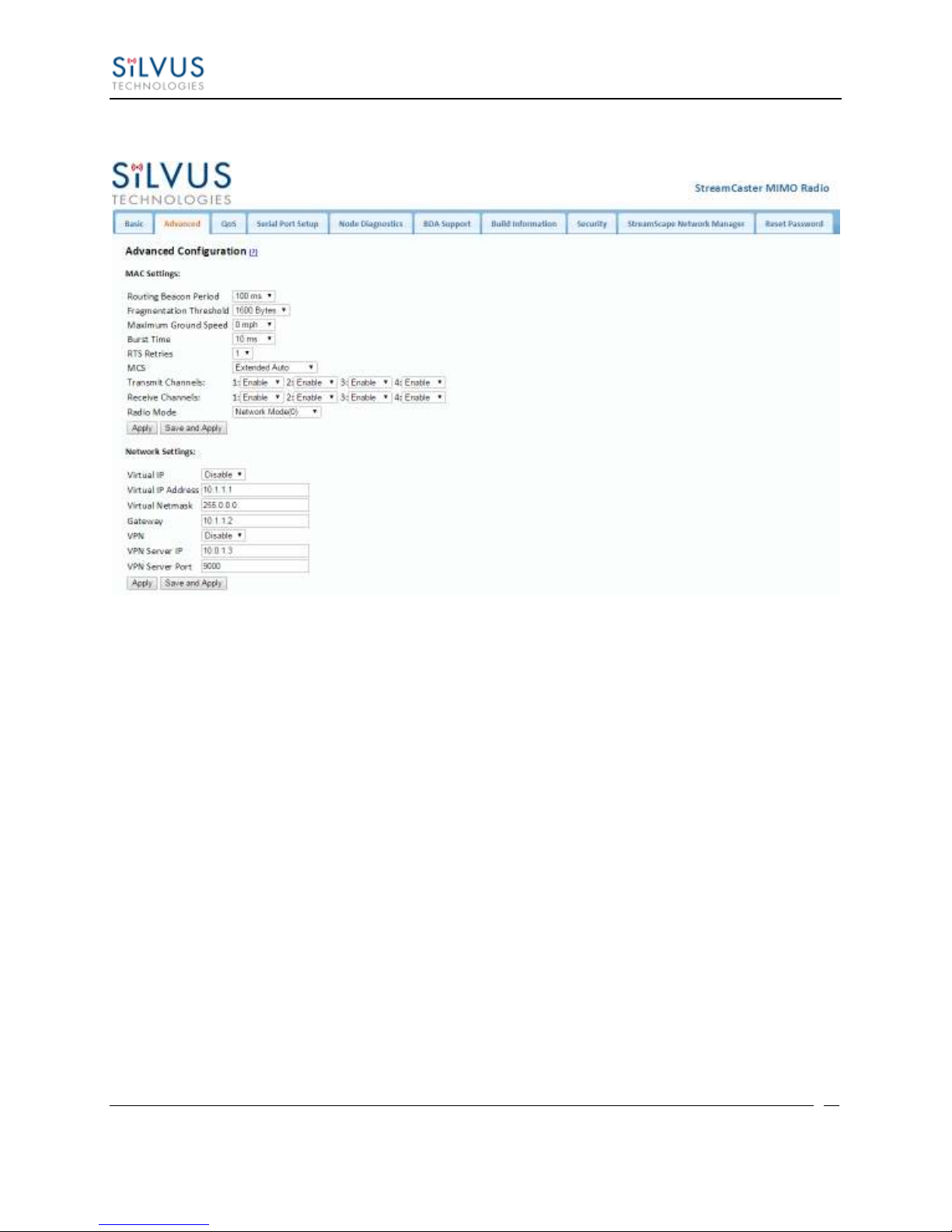
Figure 12 Advanced Configuration Page
This page is used to set advanced configurations. A brief description of each parameter is given
below.
MAC Settings:
Routing Beacon Period: Controls how often routing beacons are sent to other radios. A
lower Routing Beacon Period results in faster reaction to topology changes. A lower
Routing Beacon Period also adds more overhead to the network which scales with the
number of nodes in the network. For larger networks, a larger Routing Beacon Period is
recommended. Default value is 100ms.
Fragmentation Threshold: Allows user to determine the minimum over-the-air packet
size in bytes. Smaller packet size can improve performance in high mobility while a
larger packet size will allow for more throughput. (1600 bytes default).
Maximum Ground Speed: This setting improves performance in high mobility
scenarios where the wireless channel may change rapidly. Setting this value to an
unnecessarily high value may have an impact as high as 25 percent on overall achievable
throughput.
10017C000 Silvus Technologies Confidential Page
Page 32

StreamCaster MIMO Radio User Manual 3/17/15
30
Burst Time: The burst time determines the maximum amount of time each node is
allowed to transmit at once. A larger burst time will provide higher throughput at the cost
of higher latency. On the other hand, a smaller burst time will provide less latency at the
cost of less throughput. The throughput values shown in Table 10 and Table 12 assume
the minimum burst time.
RTS Retries: A node wishing to send data initiates the process by sending a request to
send message (RTS). The destination node replies with a clear to send (CTS) message.
Any other node that receives the RTS or CTS message will refrain from sending data for
a given time. In larger networks, there is a higher probability of collisions occurring when
an RTS is sent out. This field defines the number of retries before a packet is dropped. A
lower value will result in faster handoffs in mobile situations.
MCS: Choose the modulation and coding scheme (MCS). If this is set as AUTO, the
radio will dynamically cycle between a subset of the modes depending on the quality of
the link. This is the recommended setting for most users and will provide the maximum
data rate that the link can support. The EXTENDED AUTO mode includes 64QAM rate
modes on top of those included in the AUTO mode. Table 10 and Table 12 below show
the estimated UDP data rate and sensitivity for each MCS. This table assumes a 20MHz
bandwidth, 1000 meter link distance and 1600 byte fragmentation threshold.
Transmit Channels: Allows user to Enable or Disable each channel on the radio for TX.
Receiver Channels: Allows user to Enable or Disable each channel on the radio for RX.
Radio Mode: Switch between Network mode and PHY Diagnostics. If the value equals
0, it is in Network mode; if the value equals 1, it is in PHY Diagnostics. PHY Diagnostics
mode is only relevant for users who wish to run diagnostic tests on the radio.
Apply: Applies the new values but does not save them to flash.
Save and Apply: Save the new values to flash and apply.
Network Settings:
Virtual IP: Enable or Disable the Secondary IP address for the radio.
Virtual IP Address: Secondary IP address for the radio. The user may set this to be on
the user’s IP network, e.g., 192.168.2.10. Once this secondary IP address is set, the user
may access the radio web page using either the native IP address or the secondary IP
address. Please note that the secondary IP address should NOT be on the 172.20.xx.xx
subnet.
Virtual Netmask: Netmask for the Secondary IP address, e.g. 255.255.255.0.
10017C000 Silvus Technologies Confidential Page
Page 33

StreamCaster MIMO Radio User Manual 3/17/15
31
Gateway: Gateway for local network to allow radio to connect to the internet
VPN: For WAN wired backbone scenarios where radios from two different sites are
connected via the internet, a public N2N server is needed to route the data. Here is an
example of how to setup an N2N server on a server hosted by Amazon AWS running
Ubuntu 12.04:
Compile:
git clone https://github.com/lukablurr/n2n_v2_fork ### downloads the code
cd n2n_v2_fork
export N2N_OPTION_AES=no
make clean
make
Execute:
./supernode -l 9000 -v
Server will be running on port 9000.
VPN Server IP: IP Address of N2N VPN Server
VPN Server Port: Port that the N2N VPN server is configured to listen on.
Apply: Applies the new values but does not save them to flash.
Save and Apply: Save the new values to flash and apply.
10017C000 Silvus Technologies Confidential Page
Page 34
StreamCaster MIMO Radio User Manual 3/17/15
32
NSS
MCS
Coding Rate
PHY Throughput
(Mbps)
UDP User Throughput
(Mbps)
SC3500/SC3800
Sensitivity
SC3822
Sensitivity
1 0 BPSK 1/2
1.625
1.03
-102
-99
1 1 QPSK 1/2
3.25
2.06
-100
-97
1 2 QPSK 3/4
4.875
3.09
-97
-94 1 3
16-QAM 1/2
6.5
4.12
-95
-92
1 4 16-QAM 3/4
9.75
6.18
-92
-89
1 5 64 QAM 2/3
13
8.25
-87
-84 1 6
64 QAM 3/4
14.625
9.28
-85
-82
1 7 64 QAM 5/6
16.25
10.30
-80
-77
2 8 BPSK 1/2
3.25
2.06
-100
-97 2 9
QPSK 1/2
6.5
4.12
-97
-94 2 10
QPSK 3/4
9.75
6.18
-94
-91
2
11
16-QAM 1/2
13
8.25
-91
-89 2 12
16-QAM 3/4
19.5
12.38
-88
-85 2 13
64 QAM 2/3
26
16.21
-84
-81 2 14
64 QAM 3/4
29.25
17.62
-82
-79
2
15
64 QAM 5/6
32.5
18.94
-77
-74
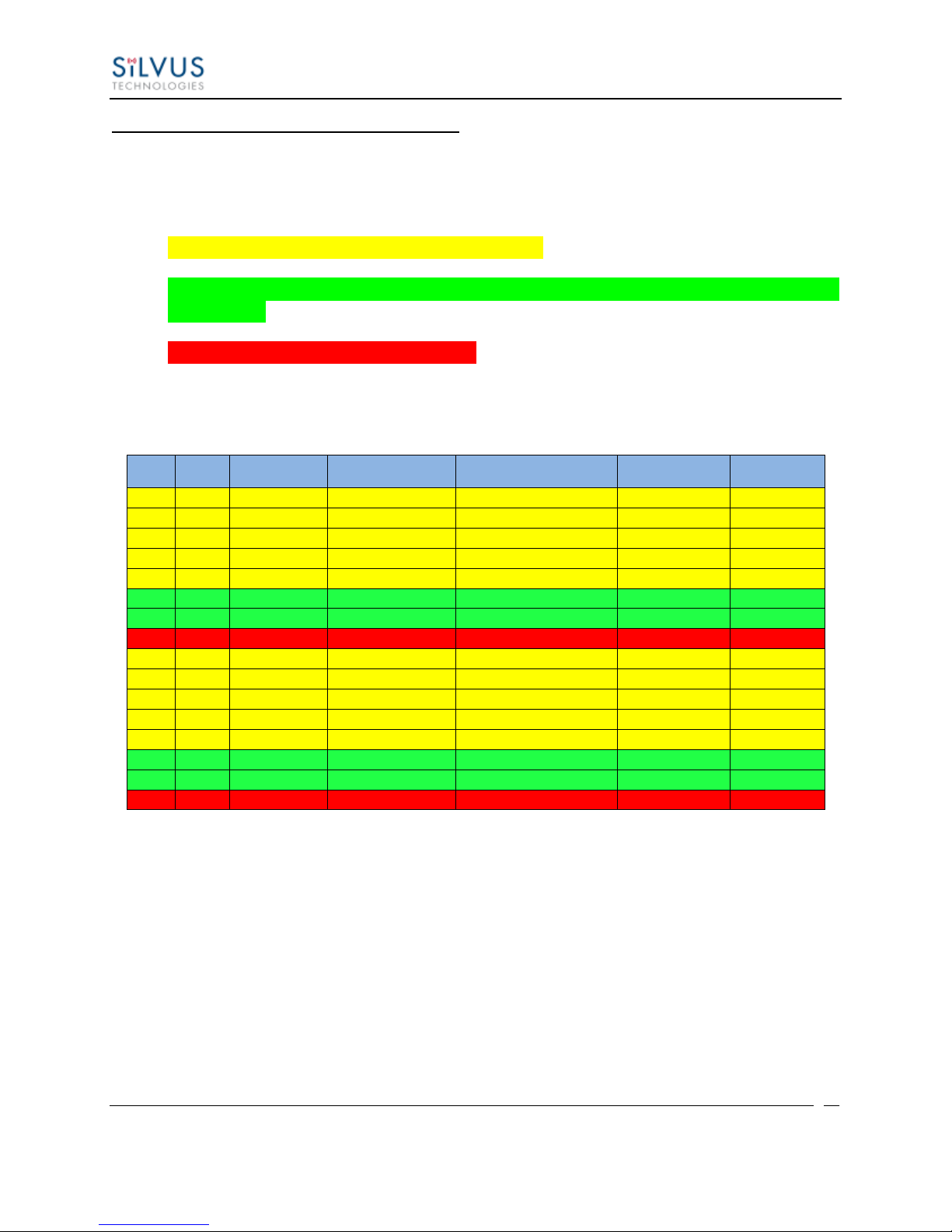
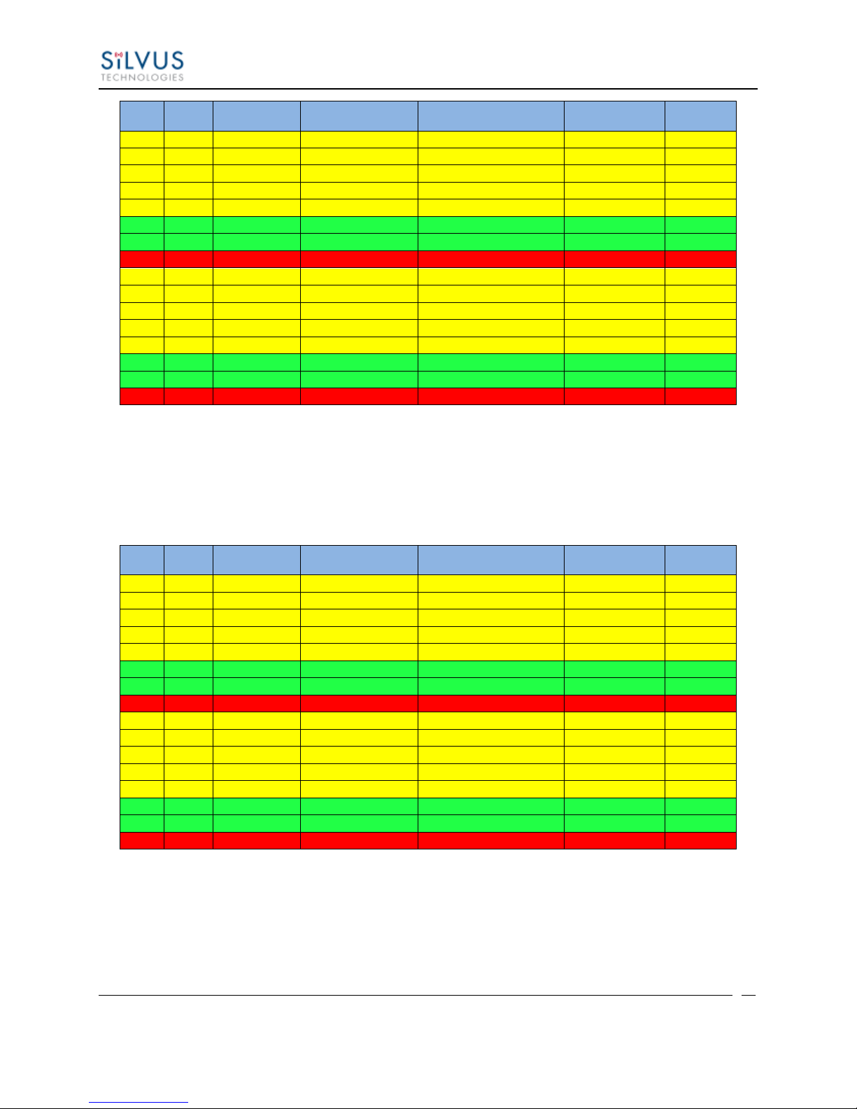
Modulation Modes and Receiver Sensitivity
Note that listed sensitivity values were measured using a controlled and cabled setup.
Actual results may vary by +/- 2dB. Table assumes link distance of 1000m, 10ms burst
time and 1600 byte Fragmentation Threshold.
* Modes supported under the AUTO MCS option.
* Modes supported under the EXTENDED AUTO MCS option in addition to AUTO
MCS modes.
* Modes that are not currently supported.
All other modes are supported as a fixed MCS option
Table 10 MCS vs. Sensitivity Chart (5MHz Bandwidth)
10017C000 Silvus Technologies Confidential Page
Page 35
StreamCaster MIMO Radio User Manual 3/17/15
33
NSS
MCS
Coding Rate
PHY Throughput
(Mbps)
UDP User Throughput
(Mbps)
SC3500/SC3800
Sensitivity
SC3822
Sensitivity
1 0 BPSK 1/2
3.25
2.48
-99
-96
1 1 QPSK 1/2
6.5
4.96
-97
-94
1 2 QPSK 3/4
9.75
7.40
-94
-91
1 3 16-QAM 1/2
13
9.90
-92
-89
1 4 16-QAM 3/4
19.5
14.80
-89
-86
1 5 64 QAM 2/3
26
19.90
-84
-82
1 6 64 QAM 3/4
29.25
22.40
-82
-80
1 7 64 QAM 5/6
32.5
24.0
-77
-78
2 8 BPSK 1/2
6.5
4.96
-97
-94
2 9 QPSK 1/2
13
9.90
-94
-91
2
10
QPSK 3/4
19.5
14.80
-91
-88
2
11
16-QAM 1/2
26
19.90
-89
-86
2
12
16-QAM 3/4
39
29.90
-85
-82
2
13
64 QAM 2/3
52
39.70
-81
-79
2
14
64 QAM 3/4
58.5
43.50
-79
-77
2
15
64 QAM 5/6
65
48.1
-74
-75
NSS
MCS
Coding Rate
PHY Throughput
(Mbps)
UDP User Throughput
(Mbps)
SC3500/SC3800
Sensitivity
SC3822
Sensitivity
1 0 BPSK 1/2
6.5
4.92
-96
-93
1 1 QPSK 1/2
13
9.82
-94
-91
1 2 QPSK 3/4
19.5
14.73
-91
-88
1 3 16-QAM 1/2
26
19.65
-89
-86
1 4 16-QAM 3/4
39
29.47
-86
-83
1 5 64 QAM 2/3
52
39.29
-82
-79
1 6 64 QAM 3/4
58.5
44.20
-80
-77
1 7 64 QAM 5/6
65
47.45
-78
-75
2 8 BPSK 1/2
13
9.82
-94
-91
2 9 QPSK 1/2
26
19.65
-91
-88
2
10
QPSK 3/4
39
29.47
-88
-85
2
11
16-QAM 1/2
52
39.29
-86
-83
2
12
16-QAM 3/4
78
57.04
-82
-79
2
13
64 QAM 2/3
104
75.00
-79
-76
2
14
64 QAM 3/4
117
75.00 (85.00 for SC3822)
-77
-74
2
15
64 QAM 5/6
130
75.00 (85.00 for SC3822)
-75
-72
Table 11 MCS vs. Sensitivity Chart (10MHz Bandwidth)
Table 12 MCS vs. Sensitivity Chart (20MHz Bandwidth)
10017C000 Silvus Technologies Confidential Page
Page 36
StreamCaster MIMO Radio User Manual 3/17/15
34
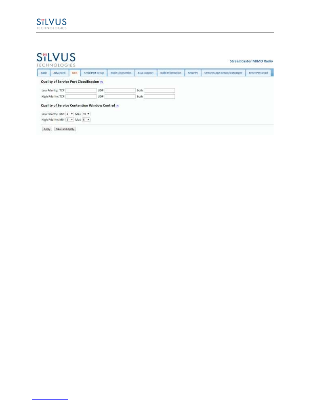
5.1.3 Quality of Service (QoS)
Figure 13 Quality of Service (QoS) Configuration Page
Quality of Service Port Classification:
The Quality of Service configuration page allows the user to make a distinction between low and
high priority traffic transmitted through each radio. High priority traffic will always jump to the
front of the queue and bypass any awaiting low priority traffic. In instances where the link
cannot support the amount of data trying to be transmitted, low priority traffic may be
completely shelved in order to ensure that the high priority traffic gets through.
To specify Low/High priority traffic, the user needs to simply input the port number that the
traffic will be arriving on. Multiple ports of the same priority can be separated by a comma (i.e.
5001, 6001, 6002). Alternatively, the user can specify a range of ports using a dash (i.e. 5001-
5006). Any combination of commas and dashes will work as well (i.e. 5001, 6001-6007, 8000).
Any field can be cleared by removing the text and clicking ‘Apply’ or ‘Save and Apply’. If
unspecified, traffic is treated as Low Priority.
Quality of Service Contention Window Control:
The Quality of Service Contention Window Control tunes the aggressiveness of CSMA backoffs
when collisions occur. The MAC takes random backoffs in the range [0, 2^cw_min]. Every time
there is a collision/noise it will increase this cw_min by 1, until it is capped by cw_max.
E.g. 4,10 translates to random backoffs in the range [0,16] in the beginning for a packet. If the
first try results in a collision, it will pick another backoff in the range [0,32], then [0,64], until
[0,1024]. After successful transmission, backoff is reset to [0,16]. The default is 4,10 for low
priority, and 3,6 for high priority. For larger networks, it is recommended to increase the Low
Priority minimum to reduce the chance of collisions occurring.
10017C000 Silvus Technologies Confidential Page
Page 37
StreamCaster MIMO Radio User Manual 3/17/15
35
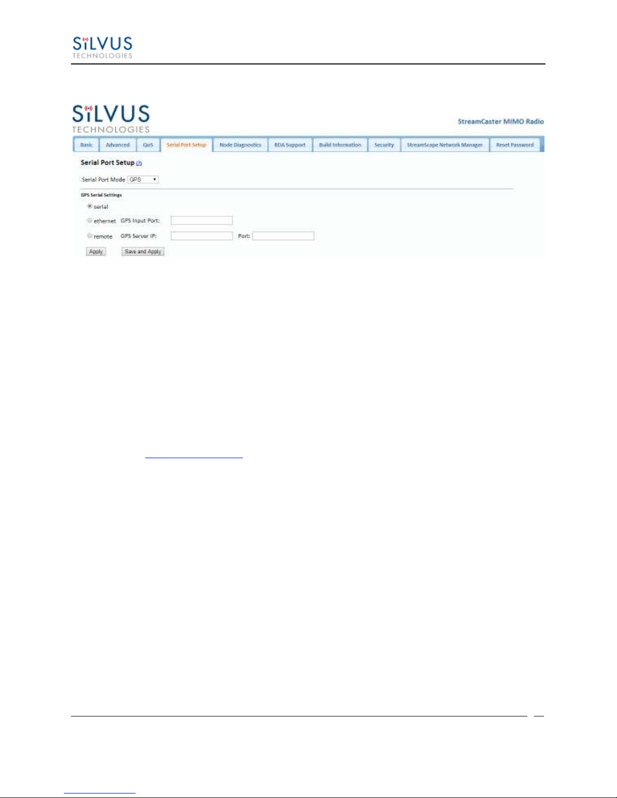
5.1.4 Serial Port Setup
Figure 14 Serial Port Setup Configuration Page (GPS Configuration)
Each StreamCaster is equipped with one user configurable serial port. A special power cable and
null modem cable are required for access to the radio’s serial port. A brief description of each
parameter is given below.
Serial Port Mode: The user can select one of four available modes for the serial port:
GPS, RS232, Console, and Disabled.
o GPS: In GPS mode, an external GPS module (MR-350 GPS Receiver) can be
connected to and powered from the serial port of the radio. A gpsd service
daemon running on the node will make the GPS information available to any user
on the network from TCP/IP port 2947. For more information on gpsd please see:
http://catb.org/gpsd/
In addition, GPS information can be fed in via the Ethernet port or pulled from a
remote device.
o RS-232: The RS-232 mode provides a wireless serial connection between any two
serial devices connected to StreamCaster nodes on the network. In this mode, the
user must configure the RS-232 protocol parameters shown in Figure 14 above.
The transport protocol for the serial data can be set as either TCP or UDP. For
data that is sensitive to latency such as command and control data, UDP is
recommended. For data that cannot tolerate any data loss, such as telemetry data,
TCP is recommended.
o Disabled: This mode completely disables the serial terminal of the radio.
Apply: Apply the new values but does not save them to flash.
Save and Apply: Save the new values to flash and apply.
10017C000 Silvus Technologies Confidential Page
Page 38
StreamCaster MIMO Radio User Manual 3/17/15
36
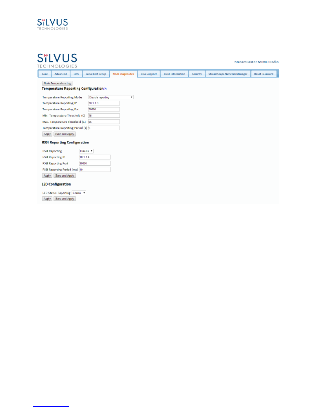
5.1.5 Node Diagnostics
Figure 15 Node Diagnostics Configuration Page
The Node Diagnostics page allows the user to specify an IP and Port number for Temperature
and RSSI (Receiver Signal Strength Indication) reports to be delivered to. This is useful for users
that intend to feed this information into some other platform for analysis and recording. Section 7
gives more information on the format of streaming reports.
Additionally, this page allows the user to disable or enable the LED on the faceplate of the radio.
Temperature Thresholds:
In addition to receiving temperature reports, this page can be used to set minimum and maximum
temperature thresholds for the radio. The StreamCaster™ family of radios is equipped with on
board temperature sensors which are monitored to prevent overheating. Once a radio reaches the
maximum temperature threshold, the radio will begin to reduce its transmission time until the
temperature falls below the minimum temperature threshold. By default, the min and max values
are 75C and 85C respectively.
10017C000 Silvus Technologies Confidential Page
Page 39
StreamCaster MIMO Radio User Manual 3/17/15
37
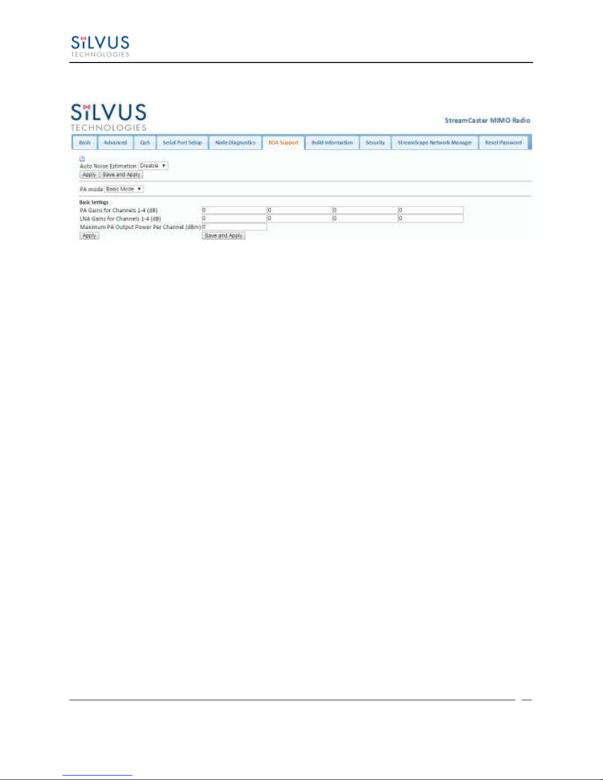
5.1.6 BDA Support
Figure 16 BDA (Bi-Directional Amplifier) Support Configuration Page
The BDA Support page is used to configure the radio to work with an external bi-directional
amplifier. These settings should be configured before connecting the amplifier to the radio.
Auto Noise Estimation: When enabled, the radio can automatically estimate the noise in
the channel, including any amplification due to the external amplifier. It is preferred that
this remain disabled and the LNA gain values be manually input further below, but if the
LNA gain values are not known, this can be used instead.
Apply: Apply the new values but does not save them to flash.
Save and Apply: Save the new values to flash and apply.
PA Mode: Either set to “No PA” when there is no amplifier present or “Basic Mode”
when using an external amplifier.
Basic Settings:
PA Gains for Channels 1-4: Enter the gain (dB) for the power amplifier connected to
each channel of the radio.
LNA Gains for Channels 1-4: Enter the gain (dB) for the LNA connected to each
channel of the radio.
Maximum PA Output Power Per Channel (dBm): Enter the maximum output power
for each PA.
10017C000 Silvus Technologies Confidential Page
Page 40
StreamCaster MIMO Radio User Manual 3/17/15
38
5.1.7 Build Information
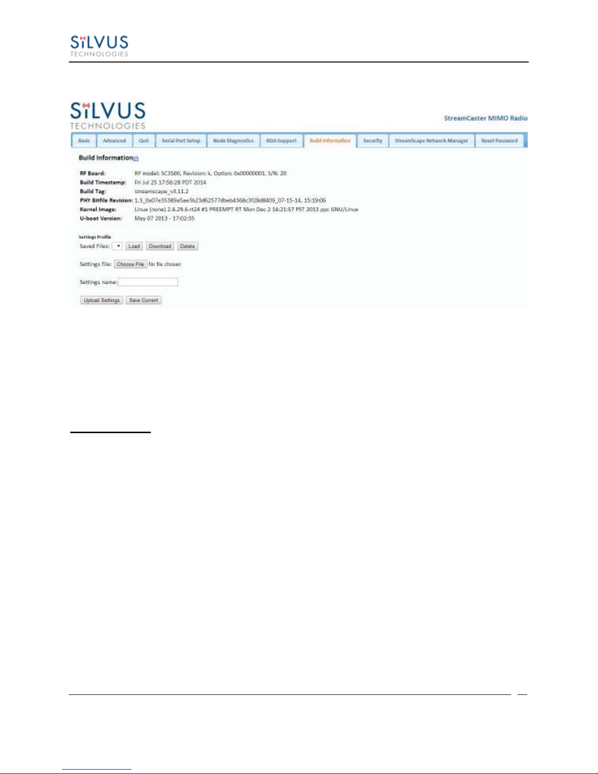
Figure 17 Build Information
On the Build Information page a user can see information about the hardware and firmware
loaded onto the radio. In addition, the user can save the current settings to a file for uploading to
other radios, or upload settings from a file to the radio.
Settings Profile:
To save the current settings to a file:
1. Type a filename into the “Settings Name” field and click “Save Current”.
2. The dropdown menu will now include this settings profile. You can choose it in the
dropdown menu and then click download to get a copy of the settings. You can also
delete it by clicking delete.
Saved profiles can be uploaded to other radios by clicking “Choose File”, browsing to the file,
and clicking “Upload Settings”.
Selecting a saved profile and clicking load will load it on the radio, so all settings will match the
profile selected.
10017C000 Silvus Technologies Confidential Page
Page 41
StreamCaster MIMO Radio User Manual 3/17/15
39
5.1.8 Security
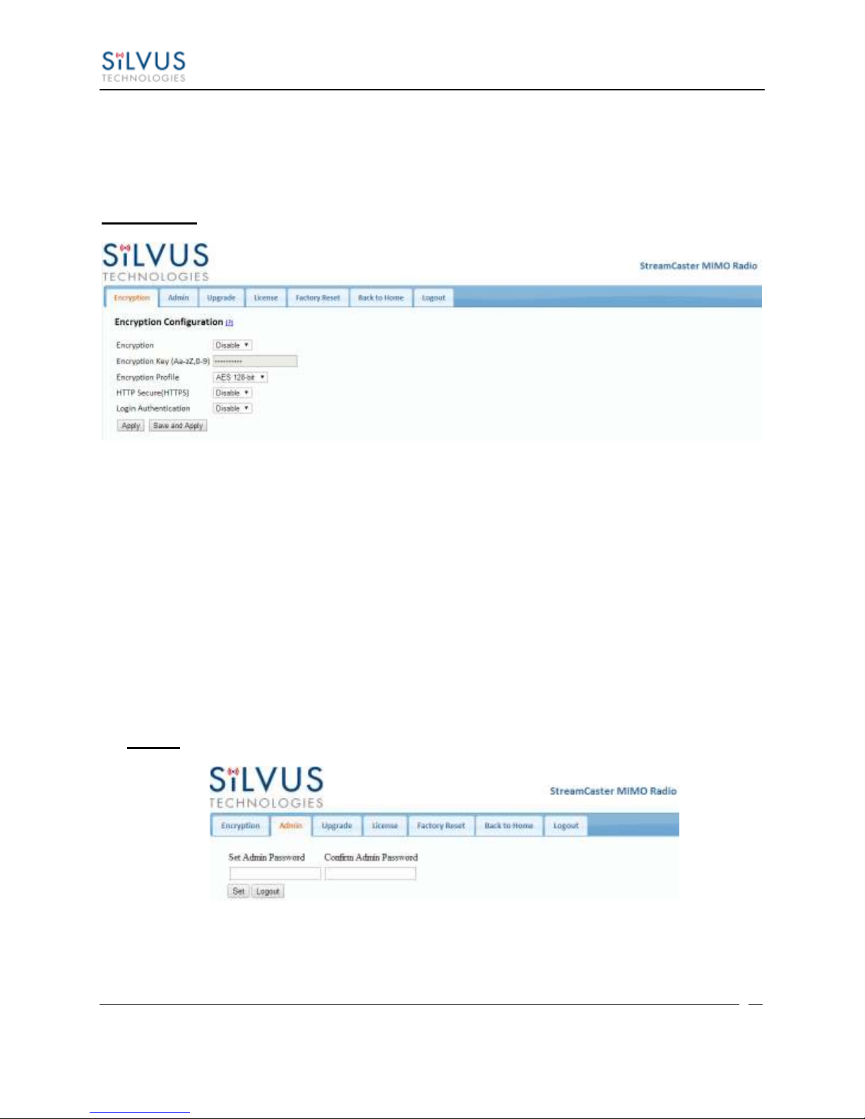
The Security section of StreamScape allows users to enable/disable encryption, upgrade radios,
and load license files for enabling features such as AES encryption.
Encryption:
Figure 18 Security (Encryption)
Encryption: Enable or disable AES encryption.
Encryption Key: Set an encryption key if encryption is enabled.
Encryption Profile: Choose between AES, DES and CCM encryption. Note that the
SC3500 and SC3800 currently only support AES and DES encryption.
HTTP Secure (HTTPS): Enable or disable HTTPS access to StreamScape.
Login Authentication: Enabling this will require the user to input login credentials
before accessing the Security section of StreamScape.
Admin:
This tab can be used to set or change the administrator password (SC3822 only).
10017C000 Silvus Technologies Confidential Page
Figure 19 Security (Admin)
Page 42
StreamCaster MIMO Radio User Manual 3/17/15
40
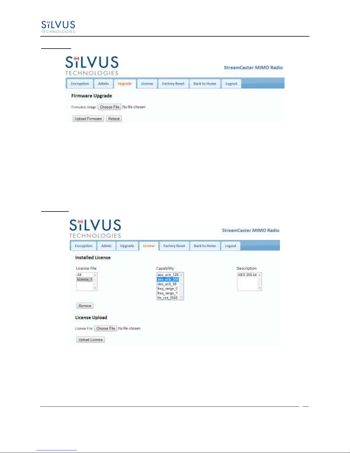
Upgrade:
Figure 20 Security (Upgrade)
The firmware can be upgraded by simply choosing the upgrade image from your desktop and
uploading it to the radio. This field can be used to upgrade the radio root file system, linux
kernel, or uboot. The upgrade system accepts the root file system image for upgrade or a tar file
containing up to 3 files (uboot, kernel, rootfs) for upgrade. A radio reboot will be required after
update before the changes take effect.
License:
Figure 21 Security (License)
Features such as encryption levels and frequency ranges can be enabled by license keys obtained
from Silvus. New license keys can be uploaded to the radio on this page.
10017C000 Silvus Technologies Confidential Page
Page 43
StreamCaster MIMO Radio User Manual 3/17/15
41
Factory Reset:
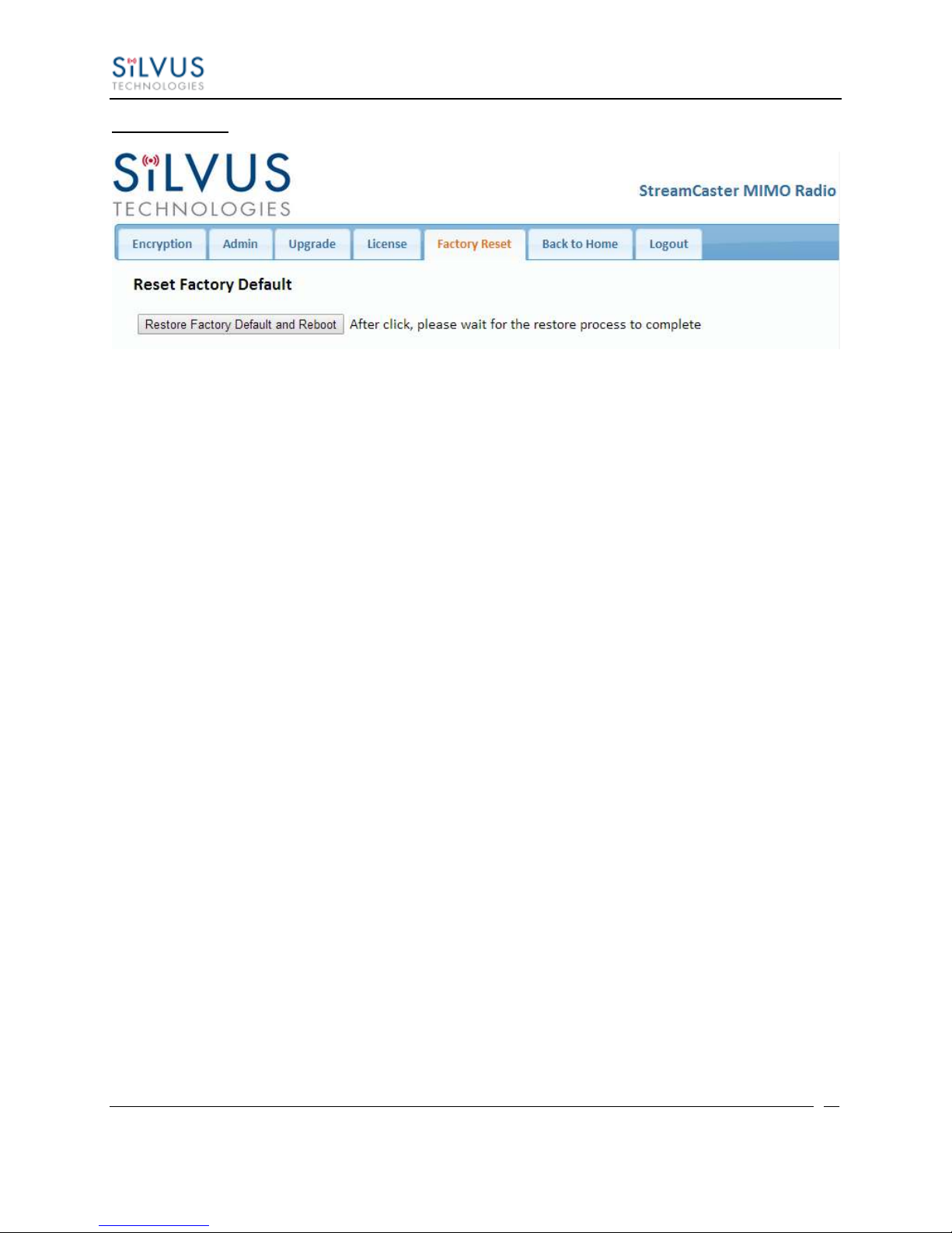
Figure 22 Security (Factory Reset)
This page allows the user to restore the settings in the radio to the factory default settings.
10017C000 Silvus Technologies Confidential Page
Page 44
StreamCaster MIMO Radio User Manual 3/17/15
42
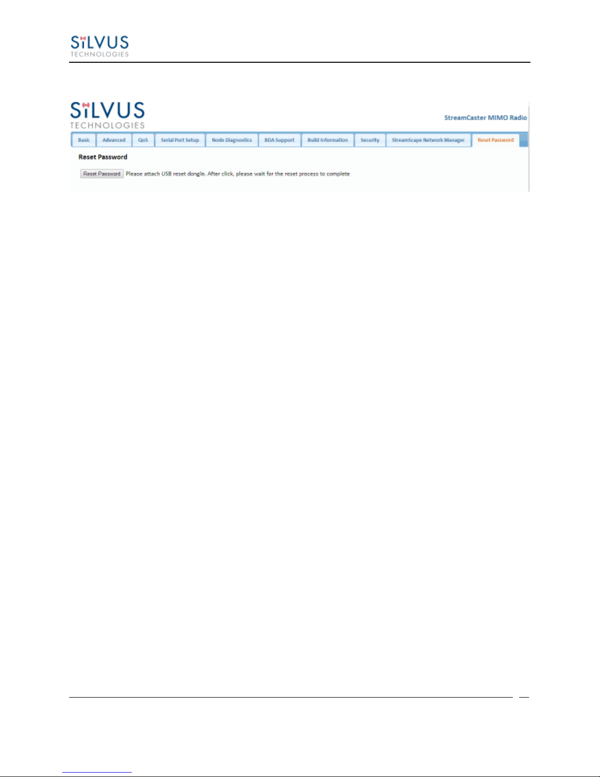
5.1.9 Reset Password
Figure 23 Security (Reset Password)
If a user forgets the password they set for the security page of StreamScape, they can reset the
password using a USB flash drive and a password reset key provided by Silvus. Note that since
the SC3500 and SC3800 do not have USB ports, you will not be able to set a password for this
section of the interface.
10017C000 Silvus Technologies Confidential Page
Page 45
StreamCaster MIMO Radio User Manual 3/17/15
43
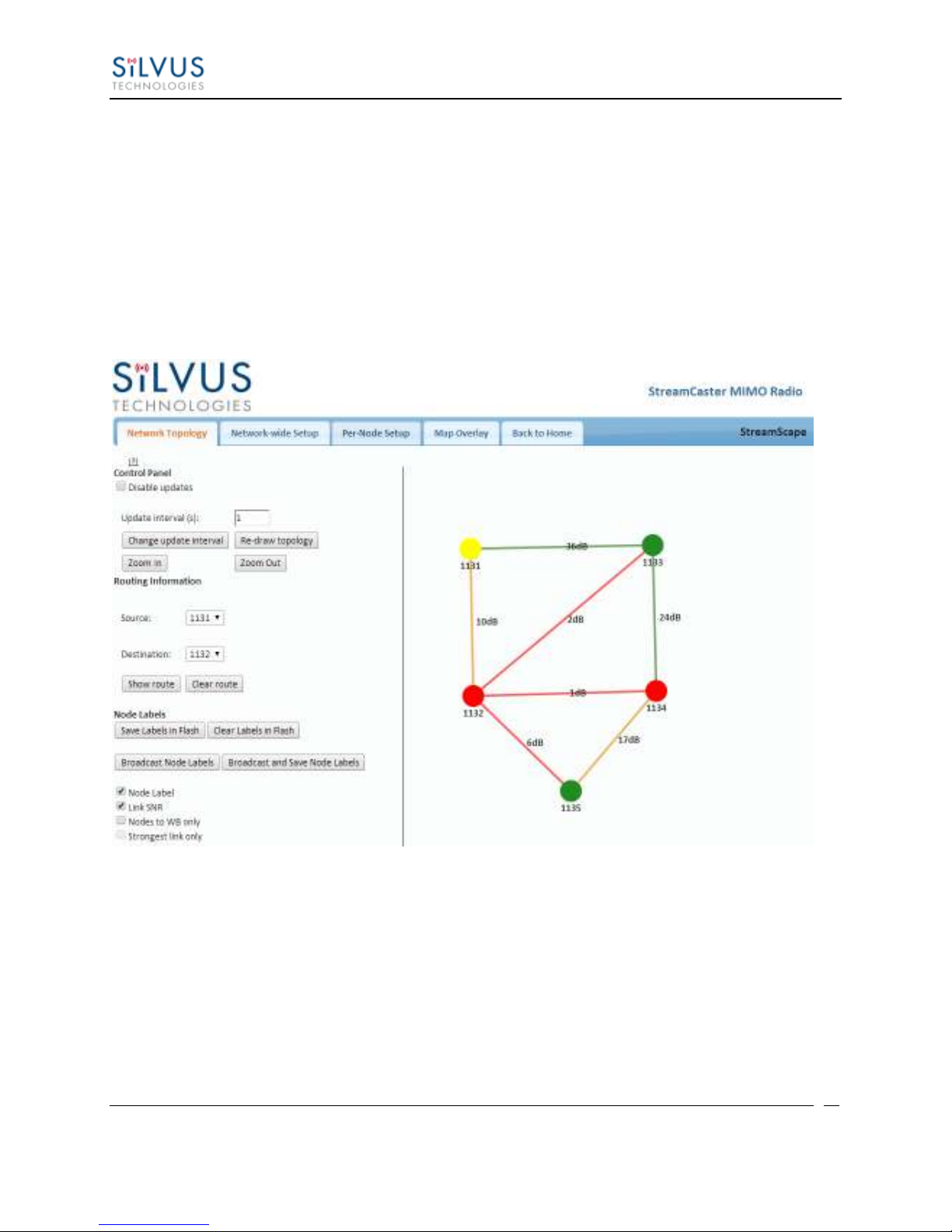
5.2 StreamScape Network Manager
Silvus’ StreamScape Network Management Utility was designed to monitor the status of a Silvus
mesh network in real-time. The graphical interface network map, shown in Figure 1, allows users
to quickly and effortlessly view the network topology and configure key parameters of the
network. For ease of use, the Silvus StreamScape utility is designed to be accessible from a
Firefox or Chrome web browser.
5.2.1 Network Topology
The network topology provides the user with real-time visual feedback of the network. Users
will be able to determine several network characteristics at a glance with the following features:
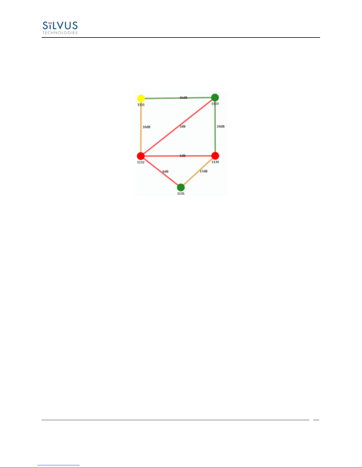
Color Coded Link Health – Color coding of each link in the network allows the user to
quickly identify the weak links within a network. A link between two nodes will
transition from green to yellow to red as the link weakens while also displaying the SNR
of the link. This can be seen in Figure 25.
10017C000 Silvus Technologies Confidential Page
Figure 24 Silvus StreamScapeNetwork Manager
Page 46
StreamCaster MIMO Radio User Manual 3/17/15
44
Route Health – The Silvus StreamScape Utility will alert the user when too many
packets are being routed through a single node. In such cases, a node will change from
green to yellow to red as the packet queue increases (see ‘1131’ and ‘1132’ in Figure
25). This will allow the user to recognize the issue and rearrange the network
accordingly.
Figure 25 Example Network Topology
Routing Information – The user can determine the routing path between any 2 nodes
within a network by simply specifying the source and destination node in the Control
Panel on the left hand side. The path will turn bold as shown in Figure 26 for the path
from ‘1131’ to ‘1135’.
10017C000 Silvus Technologies Confidential Page
Page 47

StreamCaster MIMO Radio User Manual 3/17/15
45
Figure 26 Routing Path
Custom Node Naming – Naming each node in the network is as simple as double-
clicking on the node name and typing in a new name as shown in Figure 27. This feature
enables quick identification of nodes in the field and is especially useful in mission
critical situations with many mobile assets. The user can click on the ‘Save Labels in
Flash’ button in the left pane to store the node names to the radio’s flash memory. This
will store the names on the radio even after the radio is powered off. The saved labels can
also be cleared back to the defaults by clicking ‘Clear Labels in Flash’.
Figure 27 Custom Node Naming
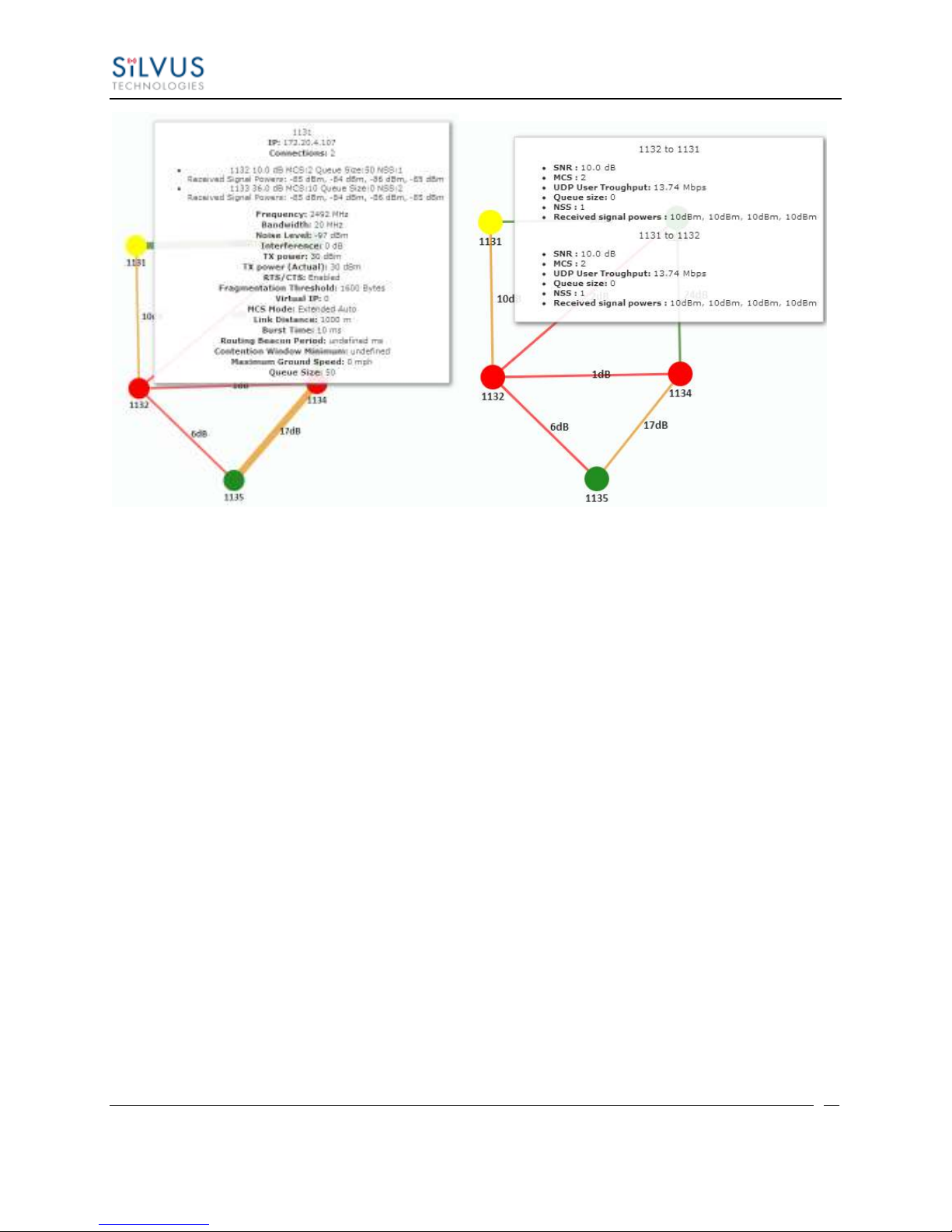
Individual Node Characteristics – By simply rolling the mouse over any node in the
network, users can view key operating characteristics of the node. Figure 28 shows an
example of this for node ‘1131’. The characteristics shown are:
10017C000 Silvus Technologies Confidential Page
Page 48

StreamCaster MIMO Radio User Manual 3/17/15
46
o Node ID: The unique node ID assigned to each node at time of manufacture. This
cannot be changed.
o IP: IP address of the node.
o Connections: Number of direct connections to node. Each directly connected
node is listed in the following format:
<Node Name> < RX SNR> <TX MCS> <Pkts in TX Queue> <Num. of Spatial Streams>
<RSSI Ch1> <RSSI Ch2> <RSSI Ch3> <RSSI Ch4>
o Frequency: RF center frequency of the node.
o Bandwidth: RF bandwidth of the node.
o Noise Level: Received noise level of the node.
o Interference: Approximate in-band interference level.
o TX Power: Total target transmit power of node.
o TX Power (Actual): Actual transmit power of node. This value may differ from
the target transmit due to temperature variation or inability to transmit a clean
signal with the selected MCS at the target power.
o Fragmentation Threshold: Chosen fragmentation threshold.
o Virtual IP: Secondary IP address of node (0 if none set).
o MCS Mode: Transmit MCS of node.
o Link Distance: Link distance setting of node.
o Burst Time: Burst time setting of node.
o Routing Beacon Period: Routing Beacon Period setting of node.
o Contention Window Minimum: Low Priority Contention Window Minimum
setting of node.
o Maximum Ground Speed: Maximum Ground Speed setting of node.
o Queue Size: Number of packets currently waiting to be transmitted.
10017C000 Silvus Technologies Confidential Page
Page 49
StreamCaster MIMO Radio User Manual 3/17/15
47
Figure 28 Individual Node Characteristics (Left), Link Characteristics (Right)
Link Characteristics – By simply rolling the mouse over any link in the network, users
can view key operating characteristics of that link. Figure 28 shows an example of this
for the link between node ‘1131’ and node ‘1132’. The characteristics shown are:
o SNR: The SNR of the link in each direction.
o MCS: The MCS used to transfer data in each direction.
o UDP User Throughput: The estimated UDP User Throughput available for each
direction of the link. This is estimated based on the current MCS used for
transmission.
o Queue Size: Number of packets in TX Queue in each direction.
o NSS: Number of Spatial Streams in each direction.
o Received Signal Powers: Received signal power for each antenna in each
direction.
10017C000 Silvus Technologies Confidential Page
Page 50
StreamCaster MIMO Radio User Manual 3/17/15
48
5.2.2 Network-wide Setup and Multicast
Using the network-wide setup users can configure key parameters of every node in the network
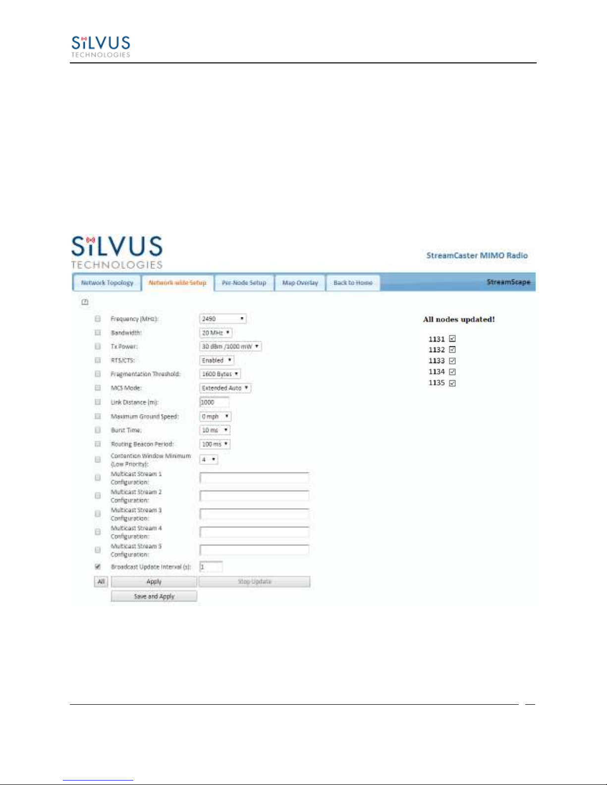
with just one click. Users simply need to check off the parameters they wish to be updated across
the network and click on Apply to apply but not write new values to flash or Save and Apply to
apply and save values to flash. The Broadcast Update Interval field determines how often, in
seconds, the new parameters will be broadcast to the entire network. A list of all nodes will
appear on the right with a check box next to each node. This box will be checked off as each
node receives the update. Once all nodes have been updated, the broadcast should be stopped by
clicking on Stop Update.
10017C000 Silvus Technologies Confidential Page
Figure 29 Network-wide Setup
Page 51

StreamCaster MIMO Radio User Manual 3/17/15
49
5.2.2.1 Multicast
The Network Wide Setup page is also used to configure up to 5 multicast streams. By default, all
multicast/broadcast flows will be sent to all radios. This configuration is only necessary if a user
wishes to send multicast streams to a subset of radios on the network. The configuration string
format is as follows:
Multicast_ip_address, receiver_id1, receiver_id2, … , receiver_idN
Multicast_ip_address is the multicast group address and receiver_idN are the node ids of the
radios that need to receive the multicast stream. If no receivers are indicated, multicast will be
sent to all radios. If there is only one receiver id = -1, the multicast stream will not be put on the
air and discarded at the transmitter. This allows a quick way for the user to turn off a multicast
stream from anywhere on the network.
Some Multicast examples:
Data for multicast group 224.50.50.51 will be received only by radios with node-ids 1131
and 1261:
224.50.50.51, 1131, 1261
Data for multicast group 224.50.50.51 will be received by all radios:
224.50.50.51,
Data for multicast group 224.50.50.51 will be discarded at the transmitter and not put on
the air:
224.50.50.51, -1
10017C000 Silvus Technologies Confidential Page
Page 52
StreamCaster MIMO Radio User Manual 3/17/15
50
5.2.3 Per-Node Setup
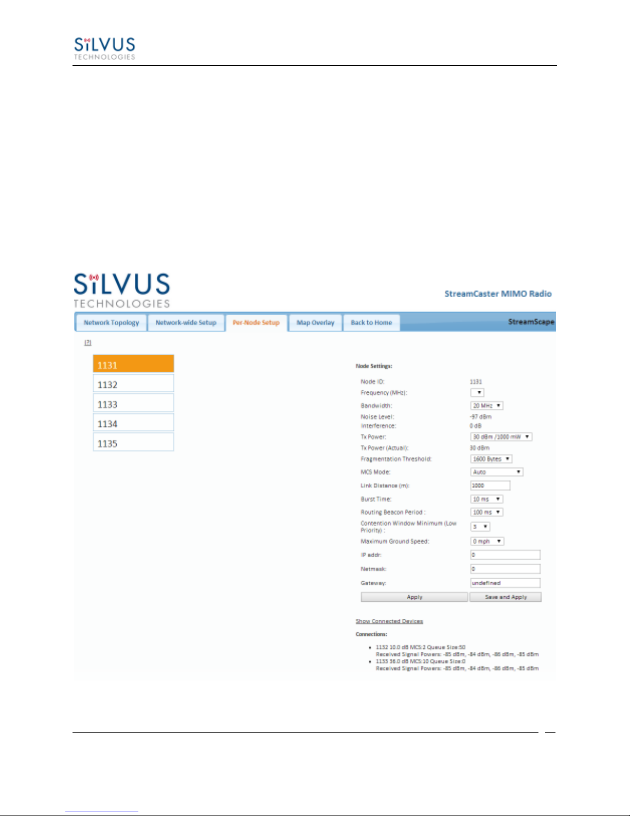
The per-node setup can be used to modify key parameters of individual nodes within the
network. As shown in Figure 30, users will see a list of all nodes available within the network.
The directly connected node is listed first with the rest ordered lexically. From here, users can
click on an individual node and modify its parameters. Any parameters changed from this
interface can either be applied or saved and applied.
In addition, this page can be used to upgrade a radio’s firmware by simply choosing the upgrade
image from your desktop and uploading it to the radio. This field can be used to upgrade the
radio root file system, linux kernel, or uboot. The upgrade system accepts the root file system
image for upgrade or a tar file containing up to 3 files (uboot, kernel, rootfs) for upgrade. A radio
reboot will be required after update before the changes take effect.
10017C000 Silvus Technologies Confidential Page
Figure 30 Per-Node Setup
Page 53
StreamCaster MIMO Radio User Manual 3/17/15
51
5.2.4 Map Overlay
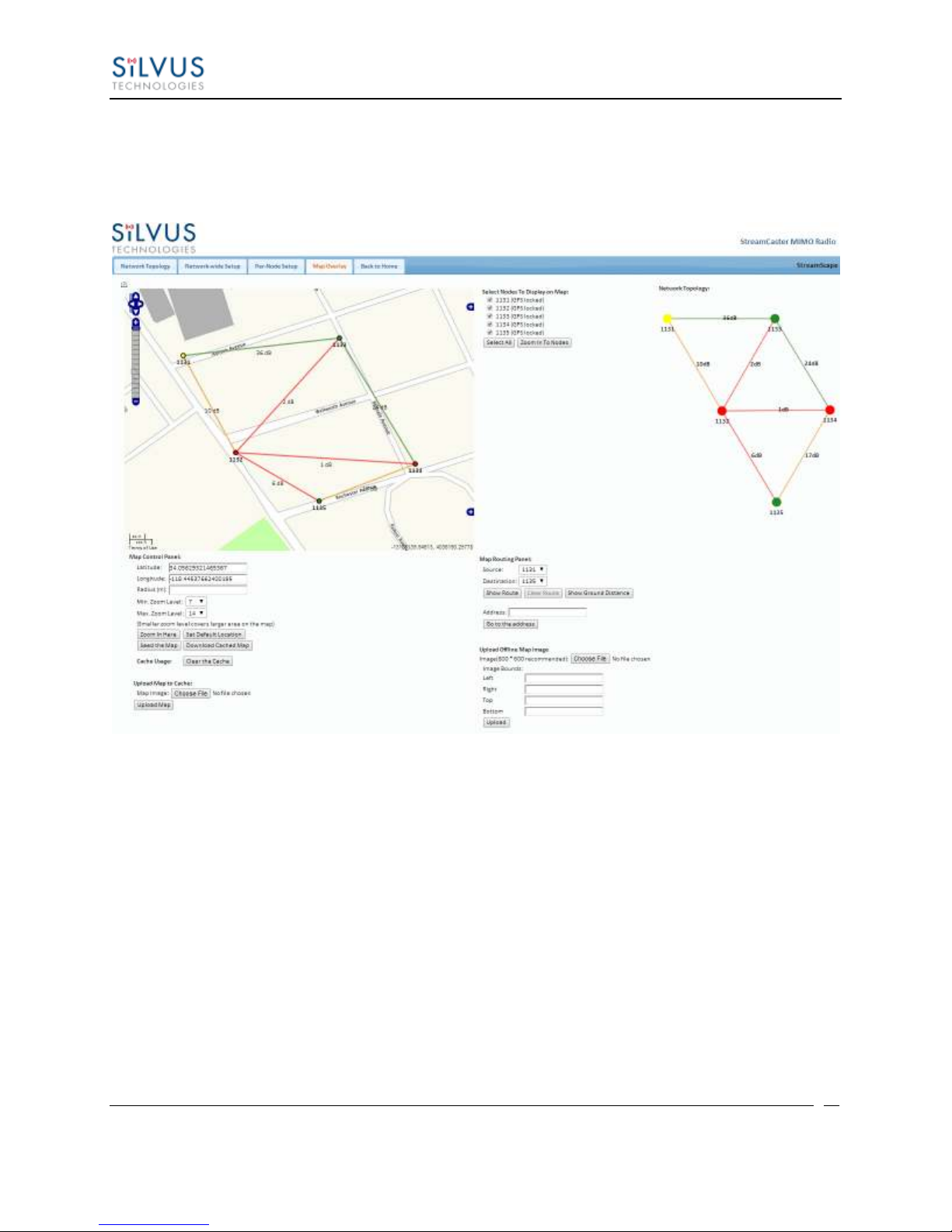
The Map Overlay page provides an easy to use method of tracking the location of nodes in realtime. Nodes with GPS modules attached will be placed on the map as shown in Figure 31.
Figure 31 Map Overlay
For convenience, a small copy of the network topology is displayed on the right hand side of the
page. This allows users to clearly view the network characteristics in instances where nodes are
physically close to one another and difficult to distinguish on the map overlay.
10017C000 Silvus Technologies Confidential Page
Page 54
StreamCaster MIMO Radio User Manual 3/17/15
52
5.2.4.1 Map Options
There are 3 map options currently available in the Map Overlay view. The default map is
OpenStreet Maps. These maps can be saved to the radio’s internal memory for offline use. For
instructions to Download OpenStreet Maps into the radio, see section 5.2.4.2.
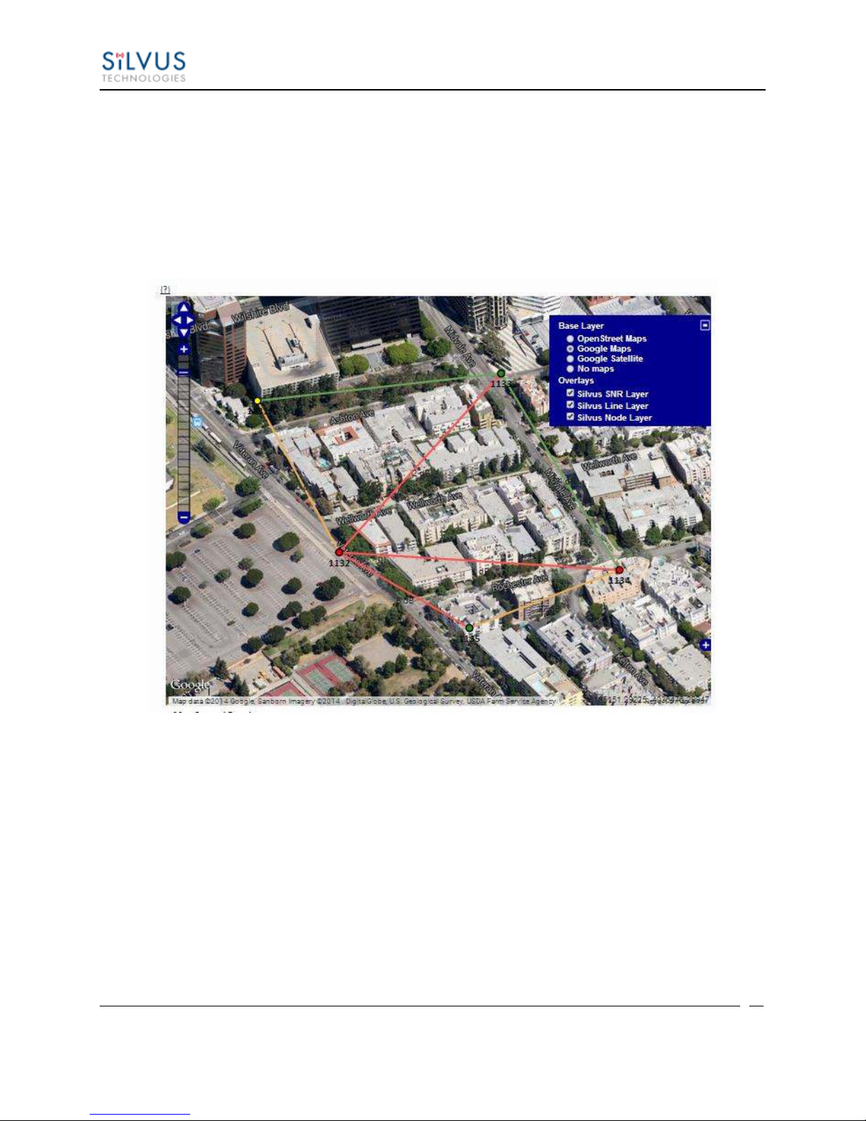
In Addition to OpenStreet Maps, Google Maps and Google Satellite are also available. This can
be changed by clicking the ‘+’ symbol at the top right of the map:
Note that Google Maps and Google Satellite require an active internet connection on the viewing
computer. These maps cannot be saved for offline use.
10017C000 Silvus Technologies Confidential Page
Figure 32 Google Maps
Page 55
StreamCaster MIMO Radio User Manual 3/17/15
53
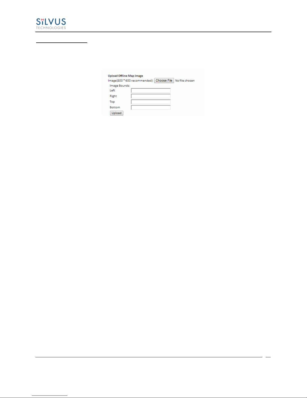
Offline Map Image:
In addition to the preset map options, the user can also upload a custom image or blueprint in
place of the map.
Figure 33 Offline Map Image
To upload a custom image (800 x 600 pixels recommended), first choose the file from your
desktop. You will then need to provide the image bounds. These bounds will be the latitude of
the left and right bounds of the image and longitude of the top and bottom bounds of the image.
Once entered, click upload and there will now be a 4th option when clicking the ‘+’ at the top left
of the map overlay.
10017C000 Silvus Technologies Confidential Page
Page 56

StreamCaster MIMO Radio User Manual 3/17/15
54
5.2.4.2 Downloading Maps
An internet connection is required to obtain map data, however, users can cache map data on a
node beforehand. For map caching follow these steps:
1. Attach the radio to a laptop and open the advanced tab.
2. Set the Virtual IP address, netmask and gateway to values appropriate for your local
network. Your local network should be able to access the internet.
3. Attach the radio to your local network and open the Map Overlay tab.
4. Input the address of the location you wish to download
5. You now have two options for caching map data:
a. Zoom/pan around the area you are interested in at the zoom level you will be
using. This will automatically cache the map data at this zoom level.
b. Fill in the radius field (in meters), set the Min/Max zoom levels and click on
‘Seed the Map’. This is a beta feature and will attempt to cache the entire area
for all appropriate zoom levels. Users should be careful in using this feature
since it may take some time and will use up the radio’s available memory. For
reference, a radius of ~3000m will use approximately 5 percent of the total
memory.
10017C000 Silvus Technologies Confidential Page
Page 57
StreamCaster MIMO Radio User Manual 3/17/15
55
5.2.4.3 Manual GPS for Nodes without GPS Module
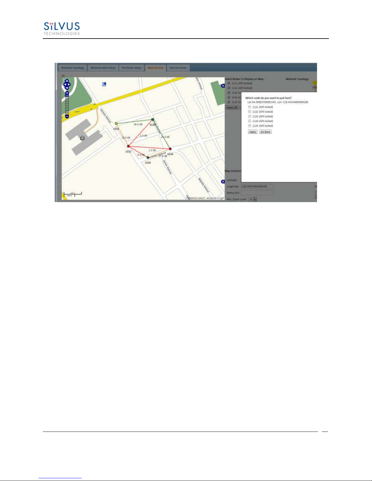
Figure 34 Placing Nodes on the Map
If there are nodes within the mesh that do not have a GPS module connected, or are located in an
area with no GPS connectivity, the user can easily place the node on the map by right clicking on
the desired location on the map and choosing which node to place there. These values will be
ignored if GPS coordinates are available via a GPS module.
10017C000 Silvus Technologies Confidential Page
Page 58

StreamCaster MIMO Radio User Manual 3/17/15
56
6. Wired Backbone
Wired Backbone extends the StreamCaster mesh functionality over LAN (Ethernet) and WAN
(Internet) links. This feature is transparent to end-users - they do not have to re-configure their
devices in any manner to use this feature.
The StreamCaster routing protocol will automatically detect and route data on wired links to
preserve air bandwidth.
6.1 LAN Backbone
The LAN backbone feature allows more than one radio to be connected to a LAN.
6.1.1 Implementation
One of these radios must be configured as a “gateway” radio. This radio then begins listening
promiscuously on its ethernet interface to “register” all devices on the LAN as being connected
to the gateway radio. At the same time it auto-detects other non-gateway radios connected to the
LAN and establishes “wired” links to them. StreamScape Web GUI will show LAN links with
SNR of 150 dB to differentiate from wireless links.
The non-gateway radios do not register any devices, they merely act as relays. The gateway radio
will forward traffic originating from the LAN, destined for a device attached to a wireless radio,
to the non-gateway radio that is closest to the destination. Similarly, any traffic originating from
a device attached to a remote wireless radio, destined to a device on the LAN will be forwarded
by non-gateway radios to the gateway radio. The gateway radio will then send it to the device.
Currently we support data rates of up to 65 Mbps on the LAN without encryption. Since all LAN
traffic goes via the gateway radio, this is the upper limit of all traffic that can enter or go out of
the LAN from/to devices connected to wireless radios. Of course, this limit does not affect the
throughput between two devices connected directly to the LAN backbone.
6.1.2 Use Case
Consider the following scenario. A business wants to do video monitoring of its grounds. High
speed LAN hookups are available only in the HQ building. They want to use the StreamCaster
radios on towers to provide complete coverage of the grounds. All video feeds are sent back and
displayed at the HQ. To conserve air bandwidth and possible interference to other users, we want
10017C000 Silvus Technologies Confidential Page
Page 59
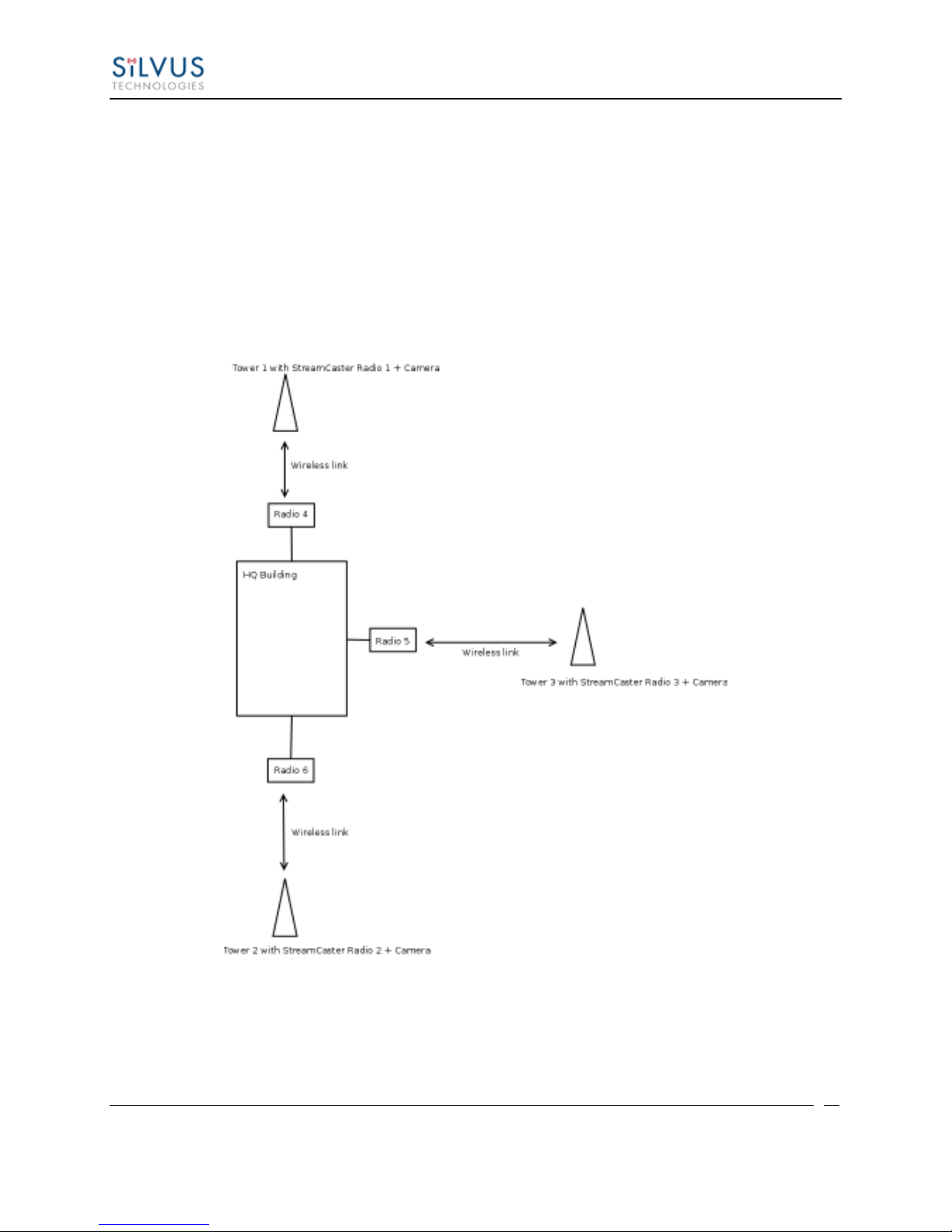
StreamCaster MIMO Radio User Manual 3/17/15
57
video data to go through the high speed LAN backbone as much as possible. The below diagram
shows the scenario.
Towers 1-3 are equipped with IP cameras attached to StreamCaster radios 1-3. Radios 4-6 are
mounted on three sides of the HQ building with their Ethernet interfaces connected to the high
speed LAN. Tower 1 can only communicate wirelessly with radio 4, Tower 3 with radio 5 and
Tower 2 with radio 6. Video from Tower 1 will flow wirelessly to radio 4, then via the LAN
backbone to the HQ viewer which is also attached to the LAN backbone. Even though the radios
4-6 may communicate wirelessly, they will choose to do so via the LAN backbone.
10017C000 Silvus Technologies Confidential Page
Figure 35 LAN Backbone Example
Page 60

StreamCaster MIMO Radio User Manual 3/17/15
58
6.2 WAN Backbone with Roaming
The WAN backbone feature allows the wireless mesh network to extend over Internet links.
Multiple geographically separate “sites” can be connected into one single layer 2 network as long
as each site has an uplink to the Internet. The roaming feature allows mobile devices connected
to StreamCaster radios to roam from one site to another without any network re-configuration.
6.2.1 Implementation
Each site wishing to become part of the wireless mesh needs to connect one StreamCaster radio
to its LAN. Such a radio has to be configured to connect to a remote VPN server using the N2N
protocol. Radios from multiple sites will be connected at layer 2 via the N2N VPN server
creating a single broadcast domain for such nodes. By broadcasting routing packets in this
domain, the nodes will auto-detect each other and establish WAN links. Such links will appear
on the StreamScape GUI with a link SNR of 120 dB to differentiate from LAN links (150 dB)
and wireless links.
The N2N VPN server will try to establish peer-to-peer links between the radios if it can. Under
some cases (e.g. symmetric NATs), this is not possible, in which case traffic between the peers is
relayed by the N2N server.
The N2N server can be hosted at any server with a public IP on the Internet. As a proof-ofconcept, a server has been set up on Amazon Web Services. Currently we support up to 10 Mbps
unencrypted between any two sites.
6.2.2 Use Case
Consider a military scenario where a platoon of soldiers begins its mission at an HQ, then breaks
up into two groups. Each group has at least one soldier with an uplink to the Internet (provided
by a 4G card). The HQ also has an uplink to the Internet. Every soldier and the HQ have a
StreamCaster radio attached to their devices.
The soldiers in the two groups want seamless and transparent communication between 1) other
soldiers in the same group 2) soldiers in the other group 3) back to HQ. Some lone soldiers (e.g.
Soldier A with a StreamCaster radio) may break up from each group and move about on their
own. As they get close to group 1, 2 or the HQ, they should be able to immediately establish
communication and talk to all other soldiers in the network.
The StreamCaster radios connected to the uplinks in Group 1-2 and the HQ will automatically
connect and form WAN links.
Note that the WAN and LAN backbone are complementary features. E.g. at the HQ, multiple
radios can be connected to a LAN backbone so that any approaching soldier or group has a direct
line of sight wireless connection to the HQ.
10017C000 Silvus Technologies Confidential Page
Page 61
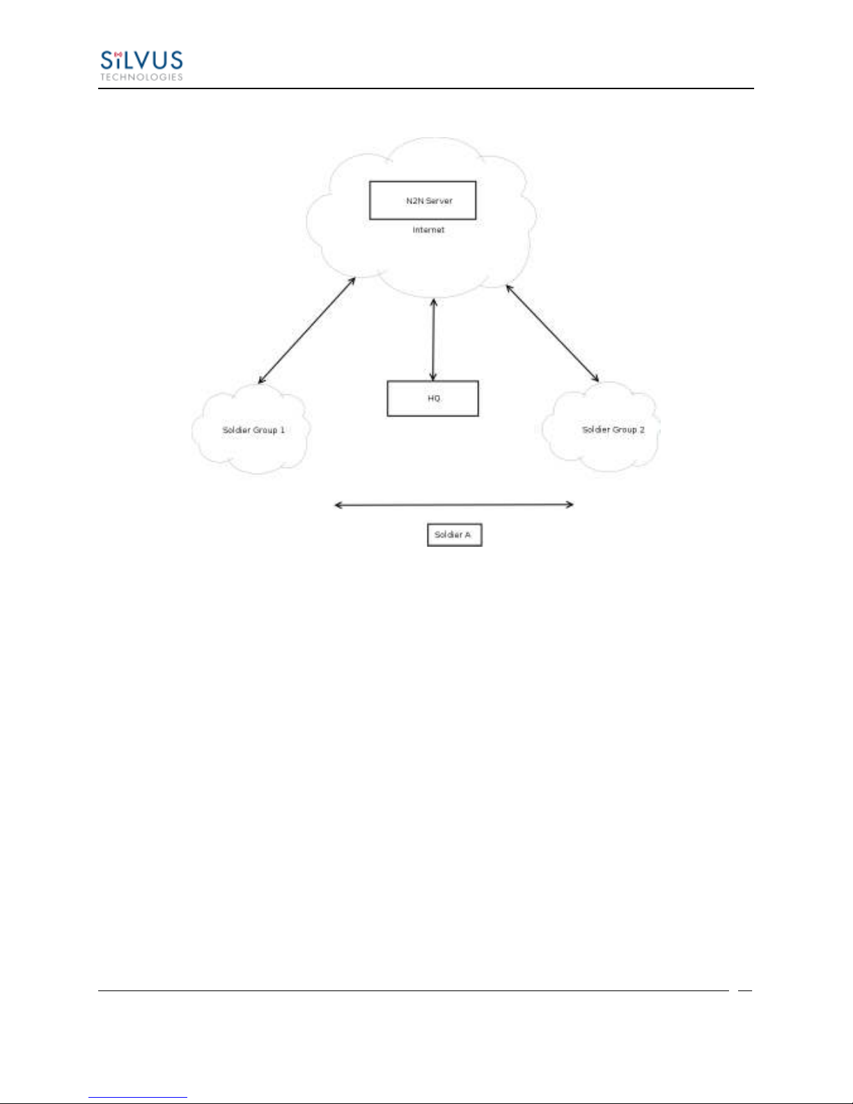
StreamCaster MIMO Radio User Manual 3/17/15
59
Figure 36 WAN Backbone Example
10017C000 Silvus Technologies Confidential Page
Page 62

StreamCaster MIMO Radio User Manual 3/17/15
60
7. Streaming Response
Some users may be interested in streaming specific information from the radio e.g. rssi, noise
floor, temperature, etc. After enabling the response they need using the above commands, the
radio will transmit the desired information in the form of UDP packets to a specific IP address
and port. The format of each report message will be in the type-length-value format as shown
below:
TYPE LENGTH VALUE TYPE LENGTH VALUE …
TYPE and LENGTH will be 16-bit unsigned integers in network-endian format.
TYPE indicates the kind of information being transmitted. Pre-defined types are listed
later in this document.
LENGTH indicates the length of the VALUE field in bytes, including the terminating
null byte.
VALUE will be ASCII-encoded text terminated with a null byte ('\0').
A single report will comprise of a set of type-length-value fields beginning with a
“begin” report type. It will have a type which is specific to the type of report being
generated, length of 1 byte and a value of an empty string (“”). Note the empty string is
still null terminated.
Each report will end with an end of report which has type 1 (type = end of report, length
= 1, value = "").
The empty string listed above has a NULL character and has length 1. Any length
number in the streaming report includes the NULL character
A UDP packet may contain more than one report.
The UDP packets have a maximum size of 1400 bytes.
7.1 RSSI and Noise Floor Reporting
The type/length/value for RSSI and noise floor reporting are listed in the following table:
10017C000 Silvus Technologies Confidential Page
Page 63
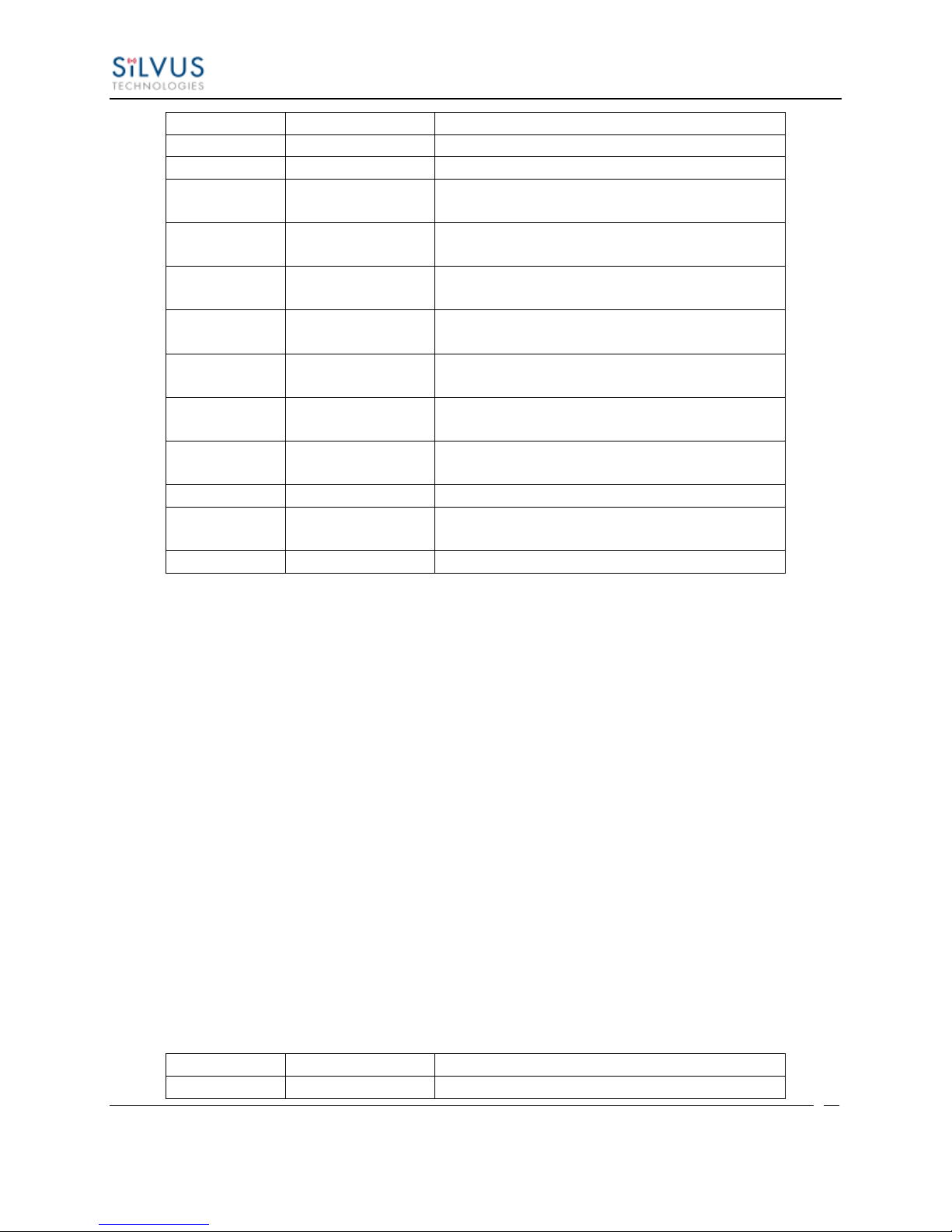
StreamCaster MIMO Radio User Manual 3/17/15
61
Report Type
Data Type
Information
5009
Empty string ""
Begin of RSSI report
5010
Float
Revision number for RSSI report
5000
Integer
Raw signal power of first antenna,
represented in half dBm steps.
5001
Integer
Raw signal power of second antenna
represented in half dBm steps.
5002
Integer
Raw signal power of third antenna
represented in half dBm steps.
5003
Integer
Raw signal power of fourth antenna
represented in half dBm steps.
5004
Integer
Raw noise power represented in half dBm
steps.
5005
32-bit integer
Sync signal power (from digital domain, see
note below).
5006
32-bit integer
Sync noise power (from digital domain, see
note below).
5007
16-bit integer
Node ID of the radio.
5008
32-bit integer
Report sequence number, increments for
every report, resets after 9999.
1
Empty string ""
End of report.
Report Type
Length
Information
5009
1
""
Table 13 RSSI Reporting Format
Note:
The sync noise and power (types 5005, 5006) are special values obtained after packet processing
in the digital domain. They cannot be directly compared to the raw signal and noise values. To
obtain an SNR from these values the user needs to run the below formula on these values:
X = sync signal power;
Y = sync noise power;
Z = (Y-X)/51
SNR_mw = (X – 12 * Z)/(64 * Z)
SNR_db = 10 * log(SNR_mw)/log(10)
SNR_db is the SNR in dB and it is averaged across all antennae.
The SNR obtained above is more accurate when the real SNR goes below 10 dB. Above 10 dB,
the SNR obtained from the raw signal and noise values are more accurate.
Below is an example of the RSSI report:
10017C000 Silvus Technologies Confidential Page
Page 64
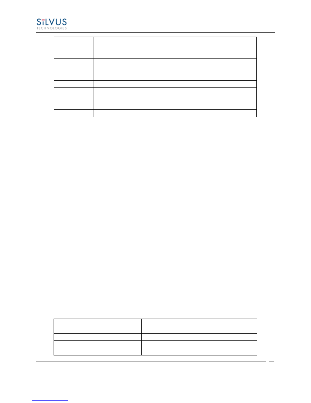
StreamCaster MIMO Radio User Manual 3/17/15
62
5010
4
"1.0"
5008
5
"2333"
5000
5
"-43"
5001
5
"-31"
5002
5
"-28"
5003
5
"-66"
5004
5
"-190"
5005
8
"8604568"
5006
8
"8861322"
5007
5
"1025"
1 1 ""
Report Type
Data Type
Data
8
Empty string ""
Begin of temperature report.
9
Float
Revision number for temperature report.
2
Integer
Current Temperature on the radio.
3
Integer
Maximum Temperature reached on the radio
Table 14 Sample RSSI Report
The corresponding raw UDP dump in hexadecimal format is attached below. For the purpose of
easier reading, each byte is separated by a space, and each item is separated by a new line. The
real streaming report is continuous without any spaces or newlines and is currently 109 bytes
long.
13 ffffff91 0 1 0
13 ffffff92 0 4 31 2e 30 0
13 ffffff90 0 5 32 33 33 33 0
13 ffffff88 0 5 20 2d 34 33 0
13 ffffff89 0 5 20 2d 33 31 0
13 ffffff8a 0 5 20 2d 32 38 0
13 ffffff8b 0 5 20 2d 36 36 0
13 ffffff8c 0 5 2d 31 39 30 0
13 ffffff8d 0 a 20 20 38 36 30 34 35 36 38 0
13 ffffff8e 0 a 20 20 38 38 36 31 33 32 32 0
13 ffffff8f 0 5 31 30 32 35 0
0 1 0 1 0
7.2 Temperature Reporting
The type, length and value for temperature reporting are listed in the following table:
10017C000 Silvus Technologies Confidential Page
Page 65

StreamCaster MIMO Radio User Manual 3/17/15
63
after last booting.
4
Integer
Overheat Count: number of times the radio
temperature has exceeded
temp_reporting_max_threshold.
1
Empty string ""
End of report
Table 15 Temperature Reporting Format
10017C000 Silvus Technologies Confidential Page
Page 66

StreamCaster MIMO Radio User Manual 3/17/15
64
8. Setting up an Iperf Test
8.1 Required Equipment
Two laptops with iperf or jperf installed. It is beyond the scope of this manual to cover
the installation and operation of these tools. The laptops must be on the same subnet but
not necessarily the same subnet as the radios (172.20.0.0). It is not required for the user to
set a secondary IP address on the radio to perform this test. It is recommended the iperf or
jperf tests are first conducted between the laptops using an Ethernet switch or cross-over
Ethernet cable between them to verify the laptops and iperf/jperf tools.
Two or more StreamCaster radios properly configured.
8.2 Running Iperf Test
Connect a laptop to one StreamCaster radio using the Ethernet cable.
Connect the other laptop to another StreamCaster radio.
Power up the radios and verify the radios are booted and connected wirelessly.
At the receiver side type the following in a terminal
o iperf –s –u -i 1
At the transmitter side type the following in a terminal
o iperf –c receiver_laptop_ip_address –u –i 1 –b 1M –t 60
10017C000 Silvus Technologies Confidential Page
Page 67

StreamCaster MIMO Radio User Manual 3/17/15
65
9. Precautions and Recommendations
9.1 Saving the Radio Configuration
It is very important that the radio does not lose power during any configuration changes in which
the user requests a “save and apply” operation. Partial saving of the configuration to the radio
due to power interruption may disable the radio requiring reprogramming at the factory. Also,
please wait for a “done” feedback at the web interface before proceeding to any other
configuration changes.
10017C000 Silvus Technologies Confidential Page
Page 68

StreamCaster MIMO Radio User Manual 3/17/15
66
10. Troubleshooting
10.1 LED Issues
If flashing red LED is present, radio is in safe boot mode. Click save and apply to
resume normal operation.
If LED is orange and node won’t connect to another node, click “restore factory
defaults” on both radios to ensure all settings are reverted to factory settings.
10.2 Intermittent Link
In a long range scenario if SNR is good but link drops unexpectedly check link distance
parameter and make sure that the link distance is set the same on all radios and
sufficiently large enough.
Check interference levels as strong interference can result in an intermittent link.
10017C000 Silvus Technologies Confidential Page
Page 69

StreamCaster MIMO Radio User Manual 3/17/15
67
11. FCC Notice (SC3500-243541 Only)
Silvus P/N: SC3500
FCC Identifier: N2S-SC3500
Equipment Class: Digital Transmission System
Maximum Power: 500mW
Antennas: 3dBi Omni Antennas (AOV3T245515575)
This equipment has been tested and found to comply with the limits for a class B digital device
pursuant to part 15 of the FCC Rules. These limits are designed to provide reasonable protection
against harmful interference in a residential installation. This equipment generates, uses and can
radiate radio frequency energy and if not installed and used in accordance with the instructions,
may cause harmful interference to radio communications. However, there is no guarantee that
interference will not occur in a particular installation. If this equipment does cause harmful
interference to radio or television reception, which can be determined by turning the equipment
off and on, the user is encouraged to try to correct the interference by one or more of the
following measures:
* Reorient or relocate the receiving antenna.
* Increase the separation between the equipment and receiver.
* Connect the equipment into an outlet on a circuit different from that to which the
receiver is connected.
* Consult the dealer or an experienced radio/TV technician for help.
In order to maintain compliance with FCC regulations, shielded cables must be used with this
equipment. Operation with non-approved equipment or unshielded cables is likely to result in
interference to radio and TV reception. The user is cautioned that changes and modifications
made to the equipment without the approval of the manufacturer could void the user’s authority
to operate the equipment.
To satisfy RF exposure requirements, this device and its antennas must operate with a separation
distance of at least 20 cm from all persons and must not be co-located or operating in
conjunction with any other antenna or transmitter.
10017C000 Silvus Technologies Confidential Page
 Loading...