

Page 1
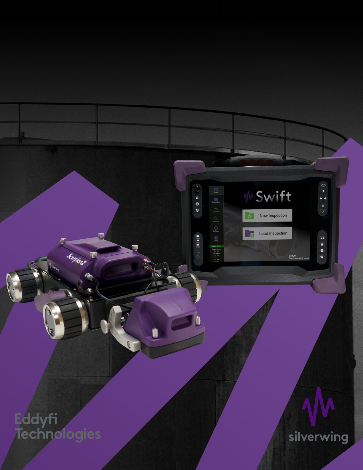
SCORPION2
USER’S MANUAL
Page 2

© Eddy UK Ltd
Clos Llyn Cwm, Swansea Enterprise Park,
Swansea,
SA6 8QY, Wales, UK.
Eddy UK Ltd (Eddy), formerly Silverwing UK Ltd is a wholly owned subsidiary of Eddy NDT Inc.
Scorpion2 User’s Manual
Manual Version 1.0
Swift Sof tware version 1.0B2T1
The text, gures and programs have been worked out with the utmost care. However, we cannot accept either
legal responsibility or any liability for any incorrect statements which may remain, and their consequences. The
following documentation is protected by copyright. All rights reserved.
Eddy reserves the right to continue developing the system and software without documenting each individual
case. Eddy holds no responsibility for any damage or destruction caused when following instructions within
this manual.
This manual is part of the original documentation supplied with the Swift instrument and Scorpion2 crawler.
14-12-2017
ii | www.silverwingndt.com
Page 3

Contents
General Precautions and Conventions
General Precautions xii
Safety Precautions xii
Conventions xiii
EMC Directive Compliance xv
Calibration and Warranty Seals xv
Limited Warranty xvi
Copyrights xvi
Chapter 1
Swift Overview
Introducing Swift 2
Starting Swift 8
Shutting Down Swift 8
Batteries 9
Chapter 2
Scorpion2 Overview
Introducing Scorpion2 12
Batteries 15
Handling Scorpion2 17
Use of the Umbilical Tail 19
Chapter 3
Software Overview
Introducing Swift Software 21
Home 21
Inspection 22
Analysis B-Scan window 28
Save Scan 31
Settings 34
Help 35
Chapter 4
Inspection Preparation
Connecting Swift to Scorpion2 37
Inspection Surface Preparation 38
| iii
Page 4

Chapter 5
Workow
Typical Inspection Workow 41
New / Load Inspection 42
Acquisition Device Calibration 43
A-Scan Conguration 44
Acquisition Mode 46
Analysis 49
Exporting Inspection Data 54
Chapter 6
Troubleshooting and Maintenance
Maintaining Swift 56
Updating and Upgrading Software 56
Troubleshooting 58
Scorpion2 Crawler Maintenance 58
Dry Coupled Wheel Probe Maintenance 59
Appendix A
Using the Optional Harness
Adjusting the Harness 62
iv | www.silverwingndt.com
Page 5

Figures
Figure 1–1 Swift front panel overview 2
Figure 1–2 Swift right panel overview 4
Figure 1–3 Swift left panel overview 5
Figure 1–4 Swift back panel overview 6
Figure 1–5 Swift in the horizontal position 7
Figure 1–6 Swift in the tilted position 7
Figure 1–7 Shutting down Swift 8
Figure 1–8 Optional battery charger 10
Figure 2–1 Scorpion2 top view 12
Figure 2–2 Scorpion2 front view 13
Figure 2–3 Scorpion2 rear view 14
Figure 2–4 Scorpion2 side view 14
Figure 2–5 Scorpion2 inserting batteries 15
Figure 2–6 Battery charger 16
Figure 2–7 Scorpion2 handling top view 17
Figure 2–8 Scorpion2 handling isometric view 17
Figure 2–9 Deploying Scorpion2 18
Figure 2–10 Removing Scorpion2 from the inspection surface. 18
Figure 3–1 Home view 21
Figure 3–2 Inspection window 22
Figure 3–3 Inspection details window 23
Figure 3–4 Acquisitions device window 24
Figure 3–5 Acquisition: B-Scan window 25
Figure 3–6 Automatic scan toolbar 26
Figure 3–7 Manual scan toolbar 26
Figure 3–8 A-Scan conguration window 27
Figure 3–9 Analysis B-Scan window 28
Figure 3–10 Export scan Window 29
Figure 3–11 Capture scan Window 30
Figure 3–12 Save scan window 31
Figure 3–13 Adjacent scan save options 32
Figure 3–14 Gridding scan save options 32
Figure 3–15 Tank shell save options 33
Figure 3–16 Settings view 34
Figure 3–17 Help 35
| v
Page 6

Figure 4–1 Scorpion2 front connectors 37
Figure 4–2 Scorpion2 rear connectors 37
Figure 4–3 Tether points 39
Figure 5–1 Typical inspection workow 41
Figure 5–1 Inspection details window 42
Figure 5–2 Select inspection window 42
Figure 5–3 Calibration window 43
Figure 5–4 A-Scan conguration 44
Figure 5–5 Load A-Scan conguration window 45
Figure 5–6 Start scan automatic window 47
Figure 5–7 Start Scan (manual mode) window 48
Figure 5–8 Load scan window 49
Figure 5–9 Amplitude view 50
Figure 5–10 Prole view 50
Figure 5–11 B-Scan analysis marker lines 51
Figure 5–12 Capture B-Scan image 52
Figure 5–13 Capture A-Scan image 52
Figure 5–14 Export scan window 53
Figure 6–1 Options menu 57
Figure 6–2 System recovery interface 57
Figure 6–3 Wheel probe removal 59
Figure A–1 Slipping the harness on 62
Figure A–2 Adjusting the shoulder straps 63
Figure A–3 Adjusting the belt’s height 63
Figure A–4 Securing the chest straps 63
Figure A–5 Securing the belt 64
Figure A–6 Shoulder anchor straps 64
Figure A–7 Unfastening the straps 65
Figure A–8 Sliding strap loop through bumper hook 65
Figure A–9 Securing anchor strap 65
Figure A–10 Alternative method of securing anchor strap to bumper 66
Figure A–11 Anchor strap on harness belt 66
Figure A–12 Slipping male buckle through bumper 66
Figure A–13 Mating battery compartment side anchor strap 67
Figure A–14 Closing battery compartment door. 67
Figure A–15 Mating shoulder anchor strap 67
Figure A–16 Tightening shoulder anchor straps 68
vi | www.silverwingndt.com
Page 7

General Precautions and Conventions
General Precautions
and Conventions
xi | www.silverwingndt.com
Page 8

General Precautions and Conventions
General Precautions
The following safety precautions are to be observed at all times when using Swift instrument
and Scorpion2 crawler. Please review them before turning on the system.
• Keep this document in a safe place for future reference.
• Carefully follow the installation and operation procedures detailed herein.
• Observe all warnings, notes and instructions as marked on the packaging, the
instrument, the crawler, and detailed in the user’s manual.
• Comply with all appropriate safety measures.
• For transportation, ensure all correct safety precautions are followed as dictated by
the relevant local governing bodies.
• Swift instrument and Scorpion2 crawler should only be used by qualied personnel.
• The equipment must not be used for purposes other than those intended. Eddy
assumes no responsibility for any damage resulting from such improper usage.
• Only connect the system to a power source corresponding to the type indicated on the
rating plate.
• Do not use substitute parts or perform unauthorized modications to the system.
• Ensure the equipment is always in safe operation condition. Qualied sta shall
perform functional tests and checks for damage at regular intervals. Authorized sta
only shall do disassembly, and according to operation instructions only.
• Ensure by regular checks that the working site, equipment and environments are kept
in a clean and clearly arranged state.
• Rules and regulations regarding the prevention of accidents that apply to the working
site should be observed.
• If the system does not operate normally, please refer to the service and troubleshooting
instructions, or contact Eddy for assistance.
Safety Precautions
During operation of Swift instrument and Scorpion2 crawler, observe the safety warnings
and precautions.
Rear Stand
Because Swift is a portable system, it is designed to be used under tough conditions. It is,
however, not indestructible. To avoid damaging Swift, use its rear stand when operating
Swift in a tilted position. Do not use Swift in the upright position, as it may topple over or
fall o the work surface.
| xii
Page 9
General Precautions and Conventions
Conventions
Typographical
The following typographical conventions are used throughout this document:
Italic
Used for le names and paths.
Bold
Used to indicate menu items, named user interfaces, and place emphasis on specic words
or phrases. Items in bold type are capitalized to reect the actual interface.
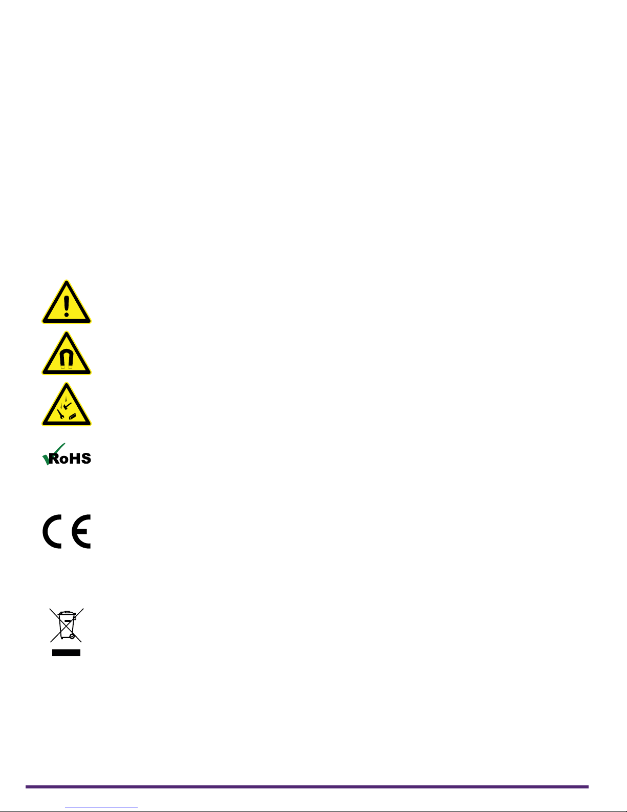
Marking and Symbols
The following symbols appear on the system and pertain to safety regulations that should
be carefully observed:
This label is used as a general warning sign. Always refer to the user’s manual to obtain the
necessary information for proper protection of the instrument and its users.
This label is used to indicate the presence of strong magnets that generate magnetic elds.
Always refer to the user’s manual to ensure proper protection and safety.
This label is used to indicate that a falling object hazard is present. Always refer to the
user’s manual to ensure correct protection and safety.
The RoHS compliance logo signies that this product complies with the Restriction of
Hazardous Substances directive 2002/95/EC. This directive restricts the use of lead, mercury,
cadmium, hexavalent chromium, polybrominated biphenyl, and polybrominated diphenyl
ether in certain classes of electrical and electronic units as of July 1, 2006.
Swift and Scorpion 2 crawler are designed to meet the safety requirements in accordance
with electrical safety and electromagnetic compatibility. It has been tested and has left
the factory in a condition in which it is safe to operate. The equipment is in conformity with
the statutory requirements of the EC directive and complies with the following provisions
of Low Voltage Directive 2006/95/EC and the Electromagnetic Compatibility Directive
2004/108/EC.
This label acts as a reminder that you should dispose of this system in accordance with your
local Waste Electrical and Electronic Equipment (WEEE) regulations. This system was
manufactured to the high quality standards of Eddy to ensure safe and reliable operation
when it is used as stated in this document. Due to its nature, this instrument may contain
small quantities of substances known to be hazardous to the environment and to human
health if released in the environment. As such, systems falling under WEEE regulations
should not be disposed of in the public waste stream.
xiii | www.silverwingndt.com
Page 10
General Precautions and Conventions
Safety Indications in This Document
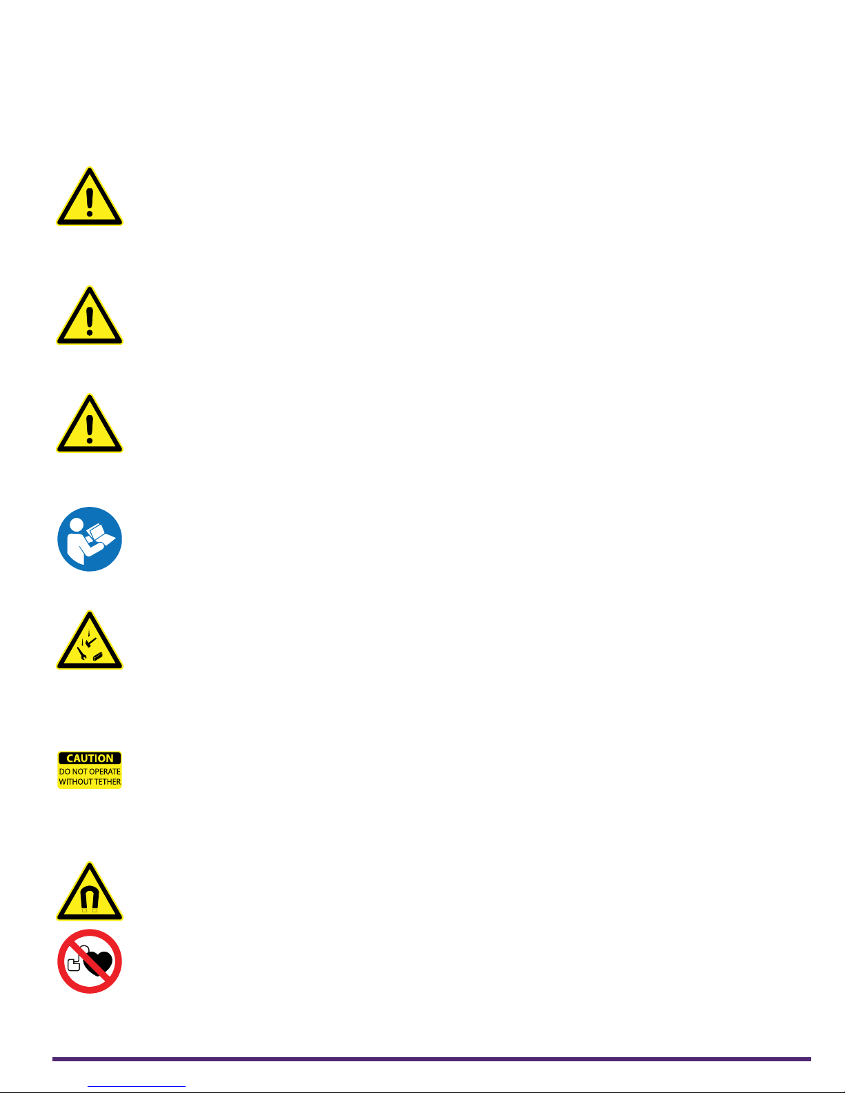
The safety indications in this document are intended to ensure operator safety and the
integrity of the system.
DANGER!
Danger statements are a description of an imminent hazardous procedure or a practice
(or the like) that, if performed incorrectly, can result in severe injury or death if not avoided
and should be limited to the most extreme situations. Do not ignore danger indications,
ensure the condition is understood before proceeding.
WARNING!
Warning statements are a description of a potentially hazardous procedure or a practice
(or the like) that, if not avoided or if performed incorrectly, could result in injury. Do not
ignore warning indications, ensure the condition is understood before proceeding.
CAUTION!
Caution statements are a description of a potentially hazardous procedure or a practice
(or the like) that, if not avoided or if performed incorrectly, could result in material damage,
loss of data, or both. Do not ignore warning indications, ensure the condition is understood
before proceeding.
READ MANUAL
Swift system is designed for a specic use. Using Swift system outside of its intended use
is dangerous. Severe injury or death could result. Read and understand this manual before
use.
DANGER FALLING OBJECT HAZARD
Failure to comply with the warnings, instructions, and specications in this manual could
result in SEVERE INJURY or DEATH.
Keep the area below an operating crawler clear at all times. A NO ENTRY ZONE must be
clearly marked and cordoned o directly below the crawler. The NO ENTRY ZONE must be
a minimum of 6m (20 ft) in all directions from the point below the crawler.
DANGER TETHER LINE
A suitable safety line must be attached to the attachment points of Scorpion2 crawler at
all times during operation. Attach the tether line BEFORE placing Scorpion2 crawler onto
the inspection surface.
WARNING MAGNETIC MATERIAL
Due to magnetic material, consult IATA documentation before air shipping.
The wheels and probe holder of the crawler contain strong magnets that produce an
extremely strong magnetic eld which may cause failure or permanent damage to items
such as watches, memory devices, CRT monitors, and medical or other electronics devices.
Strong magnetic elds pose a variety of risks, especially to people who wear implanted
cardiac devices like pacemakers and debrillators.
| xiv
Page 11

General Precautions and Conventions
WARNING FINGER TRAP
Tools, magnets, and metal objects can cut, pinch, or entrap hands and ngers. HANDLE
WITH CARE. People with pacemakers or ICD’s must stay at least 2 m (6.5 ft) away.
WARNING RISK OF EXPLOSION
Damage to the crawler and/or cables during or prior to use may cause explosion or re.
IMPORTANT
Calls the attention to information important to completing tasks.
NOTE
Calls the attention to an operating procedure, a practice, or the like that requires special
attention.
EMC Directive Compliance
FCC Compliance (USA)
This equipment was tested and found to comply with the limits for a Class A digital device,
pursuant Part 15 of the FCC Rules. These limits are designed to provide reasonable protection
against harmful interference when the equipment is operated in a commercial environment.
This equipment generates, uses, and can radiate radio frequency energy and, if not installed
and used in accordance with the user’s guide, may cause harmful interference to radio
communications. Operation of this equipment in a residential area is likely to cause harmful
interference in which case you will be required to correct the interference at your own
expense.
ICES Compliance (Canada)
This ISM device complies with Canadian ICES-001.
AS/NZS Compliance (Australia/New Zealand)
This device complies with Australia and New Zealand AS/NZS 4252.2 (IEC 61000-6-4) and
AS/NZS61000-6-2 (IEC 61000-6-2).
Calibration and Warranty Seals
The calibration seal is at the back of the instrument. Swift is also equipped with a warranty
seal.
Important
Broken seals void the calibration certication and product warranty.
xv | www.silverwingndt.com
Page 12

General Precautions and Conventions
Limited Warranty
Eddy warrants the hardware to be free of any defects in materials or workmanship for a
period of twelve (12) months from the date of delivery, under normal use and service. These
warranties are limited to the original purchase of the product and are not transferable.
Eddy will repair or replace any product component or documentation, at its option and
at no additional charge, if found defective within the warranty period. The purchaser is
responsible for returning the product to Eddy.
Eddy will not be held responsible in any way whatsoever for damage resulting from
improper installation, accident, misuse, or from service or modication of the product by
anyone other than Eddy, or an authorized Eddy service center.
Eddy will not be held responsible in any way whatsoever for direct, indirect, special,
incidental, or consequential damages resulting from possession, use, improper installation,
accident, service, modification, or malfunction of the product (including, without
limitation, damages for loss of business prots, business interruption, loss of business
information, or other pecuniary loss). Eddy’s total shall in no event exceed the purchase
price of the applicable item(s).
This warranty is in lieu of all other warranties, whether oral, written, expressed, or implied,
including any warranty of merchantability or tness for a particular purpose, and no other
representation or claims of any nature shall be binding on or obligate Eddy.
Copyrights
This document and the product and programs it describes are protected by copyright laws
in the UK, by laws of other countries, and by international treaties, therefore may not be
reproduced, in whole or in part, whether for sale or not, without prior written consent from
Eddy UK Ltd. Under copyright law, copying includes translation in other languages and
formats.
© Eddy UK Ltd, 2017
This document was prepared with particular attention to usage to ensure the accuracy of
the information it contains. It corresponds to the version of the product manufactured
prior to the date appearing on the inside front cover. There may, however, be some
dierences between this document and the product, if the product was modied after
publication.
The information contained in this document is subject to change without notice.
| xvi
Page 13

Swift Overview
Chapter 1
Swift Overview
1 | www.silverwingndt.com
Page 14
Swift Overview
Introducing Swift
Swift is a battery-powered Ultrasonic Data Acquisition instrument designed to control Scorpion2 crawler.
What’s in the Box
Swift comes supplied with the following standard accessories:
• Two, high-capacity batteries
• One power adapter (100–240 V)
• Power leads
Swift Overview
Front
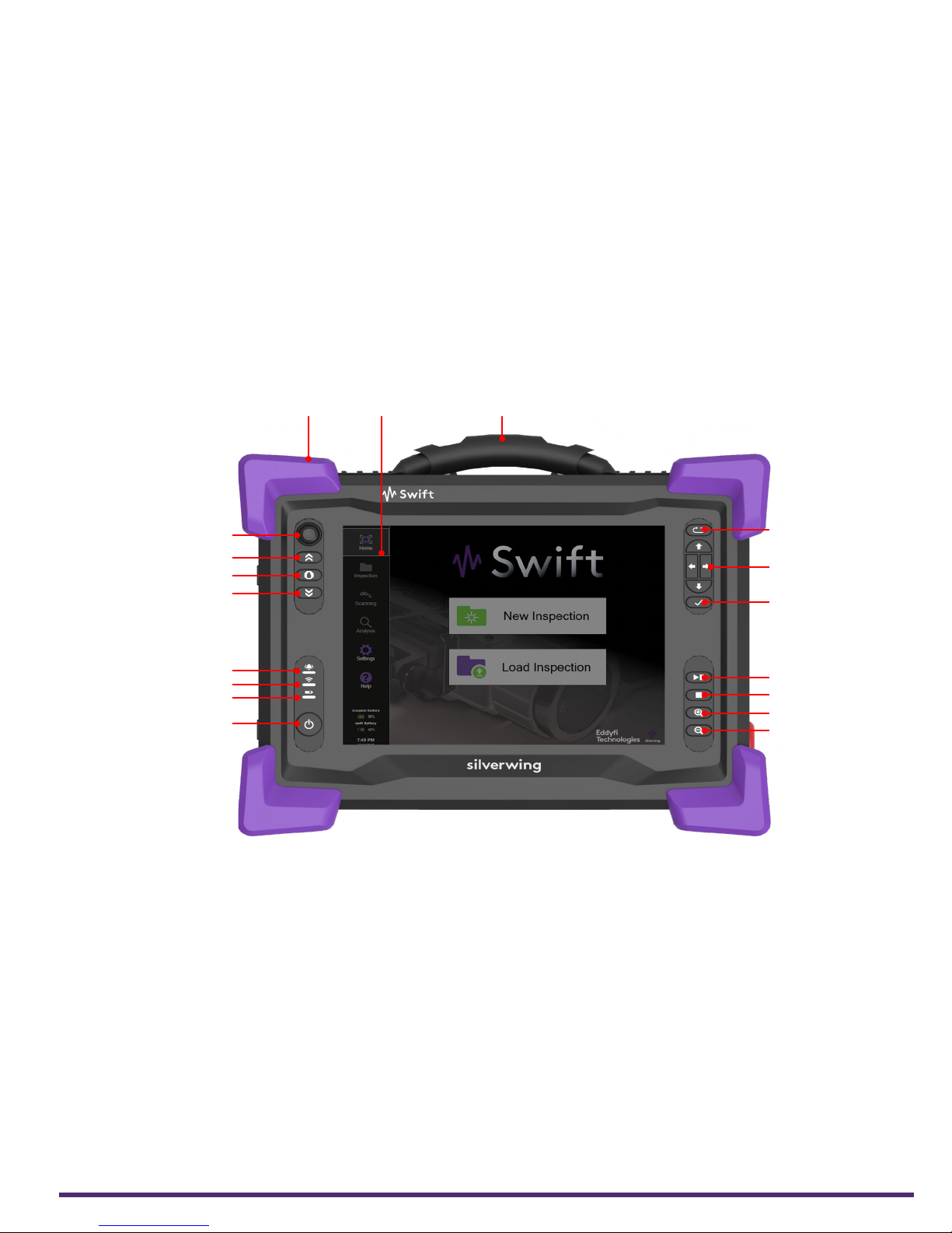
Figure 1–1 Swift front panel overview
109
8
7
6
5
4
3
2
1
• Battery charger
• Stylus
• Transport case
11
12
13
14
15
16
17
18
1. Power button
Use this button to turn the instrument
on and o. The power indication at the
center of the button behaves as
follows:
• Green: Swift is on
• Flashing yellow / orange: Swift is in
standby mode
• Unlit: Swift is o
2. Battery indicator
This displays the state of Swift
batteries when the instrument is on.
Dependent upon the power mode
(mains or battery power) the indicator
behaves dierently.
Mains power
• Green: batteries fully charged
• Flashing green: batteries charging
• Red: battery or charger error
• Unlit: no batteries in Swift
Battery power
• Unlit: remaining charge over 40%
• Orange: remaining charge 20-40%
• Flashing yellow: remaining charge
less than 20%
• Red: battery error
| 2
Page 15
Swift Overview
3. Wi-Fi indicator
This displays the Wi-Fi status of Swift:
• Green: Wi-Fi enabled
• Unlit: Wi-Fi disabled
4. Alarm indicator
This indicator is used to display userprogrammed errors. The indicator
remains unlit until it detects a
predened error condition.
5. Backwards nudge
Hold this button to drive Scorpion2
crawler backwards.
6. Stop movement
Press this button to stop Scorpion2
cra w le r.
7. Forwards nudge
Hold this button to drive Scorpion2
crawler forwards.
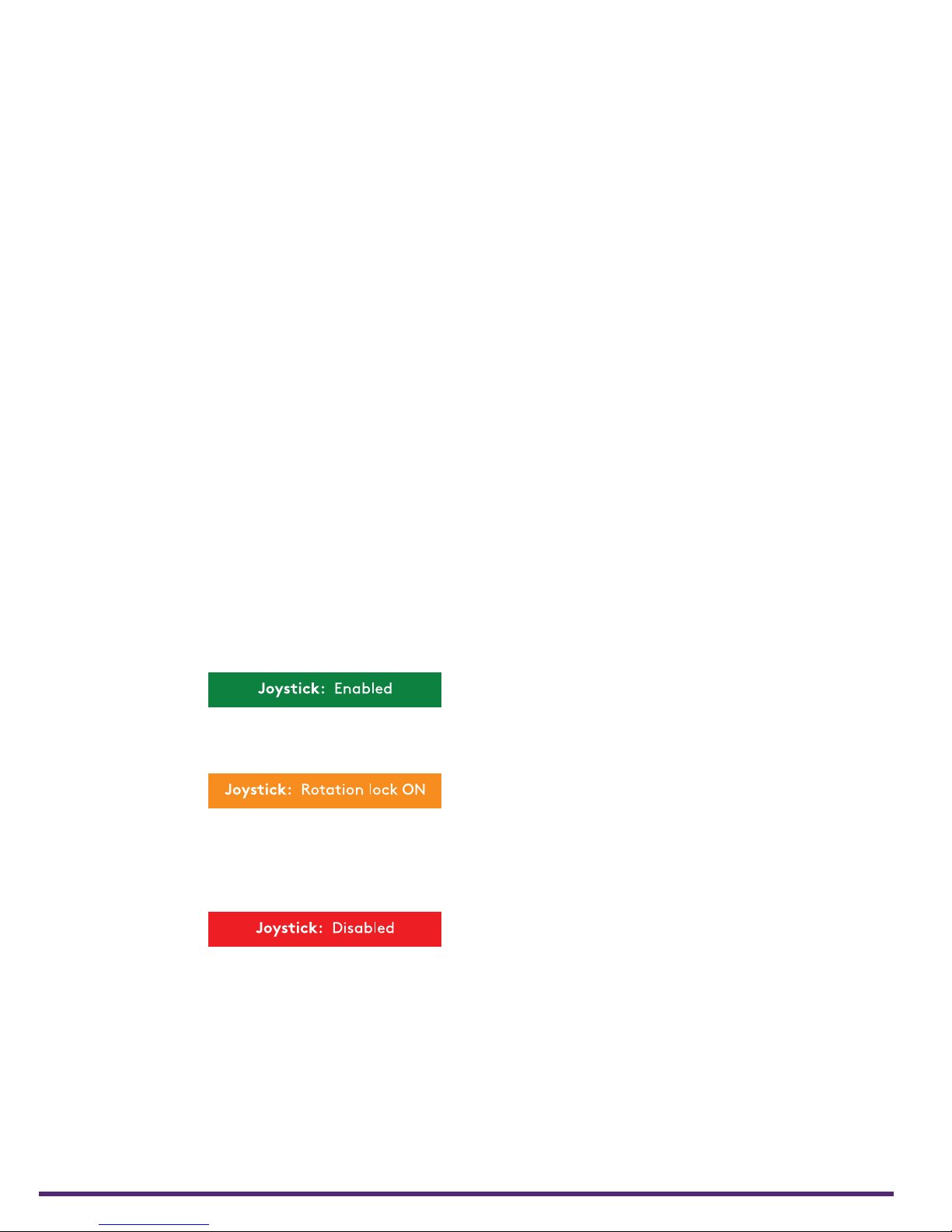
8. Joystick
This is used to drive and steer Scorpion2
crawler when a connection is
established.
The movement of the crawler depends
upon the joystick status indicated in
Swift software.
10. Multi-touch display
10.4 ″, non-reflective, backlit, high-
resolution display.
11. Handle
Use this handle when carrying Swift.
12. Back button
Press this button to navigate
backwards through Swift software
interface.
13. Keypad arrows
The use of the arrows is dependent
upon the view in Swift software
interface.
Up/Down arrow
In A-Scan Conguration view, these
adjust the step/pre-set value of the
selected A-Scan property.
In Analyse view, they control the
vertical crosshair cursor position on
the B-Scan.
Left/Right arrow
In A-Scan Conguration view, these
arrows increase or decrease the
selected A-Scan property by the step/
pre-set value.
This allows both drive and steer control
over the crawler.
This allows only forwards and
backwards movement of the crawler
with slight veering control to adjust
driving direction.
The joystick will not move the crawler.
9. Heavy-duty bumpers
The four corner bumpers provide shock
absorption and support Swift at an
angle when set on a at surface. The
bumpers also act as a harnessing
point for the instrument. For details
about harnessing, see Appendix A.
In Analyse view, they control the
horizontal crosshair cursor on the
B-Scan.
14. Enter button
Press this button in the A-Scan
Congurations view to apply the step/
preset value to the selected A-Scan
property.
15. Start/Pause scan button
Use this button to start or pause the
data acquisition scan.
16. Stop scan button
Use this button to finish the data
acquisition scan.
17. Zoom in
Use this button to zoom in on the
B-Scan in Analysis view.
18. Zoom out
Use this button to zoom out of the
B-Scan in Analysis view.
3 | www.silverwingndt.com
Page 16
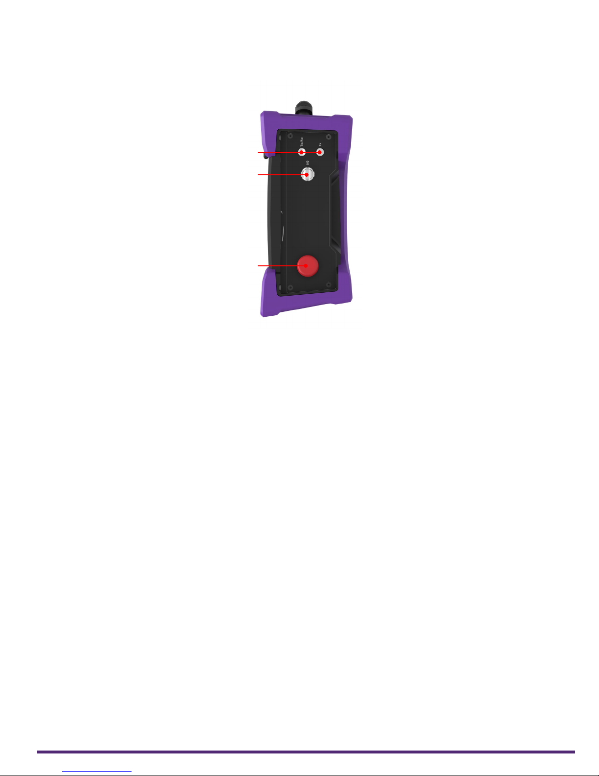
Right
Figure 1–2 Swift right panel overview
1
2
3
Swift Overview
1. UT connectors
Use these connectors for the ultrasonic
transmit and receive connectors.
2. I/O connector
Use this connector to communicate
with Scorpion2.
3. Emergency Stop
Use this to disconnect both
communication and power to
Scorpion2. Reset by rotating clockwise.
| 4
Page 17

Swift Overview
Left
Figure 1–3 Swift left panel overview
2
1
9
1. Protective connector door
Protects Swift’s powerful connectivity
from the elements when they are not
in use.
2. Quick Copy
Not currently supported on Swift.
3. Audio connector
Not currently supported on Swift.
4. HDMI® connector
Use this to connect an external
monitor to Swift.
5. Network connector
Use this connector to hook up Swift to
a local area network (LAN). This
connector is equipped with two
indicators with the following behavior:
Connection indicator (upper)
• Green: communication established
between Swift and the network
• Flashing green: activity between
Swift and the network
• Unlit: no link to network
3
4
5
6
7
8
Connection speed indicator (lower)
• Amber: operating at a gigabit
connection (1 Gbps)
• Green: operating at a 100 Mbps
connection
• Off: operating at a 10 Mbps
connection
6. USB 2.0 connectors
Use these to connect USB devices to
Swift, such as a mouse or external disk
drive.
7. Power connector
Use the AC power adaptor to recharge
the batteries.
8. Battery compartments
Insert the supplied batteries into the
appropriate battery compartment.
9. Protective battery compartment
door
Protects the battery compartments
from the elements.
5 | www.silverwingndt.com
Page 18
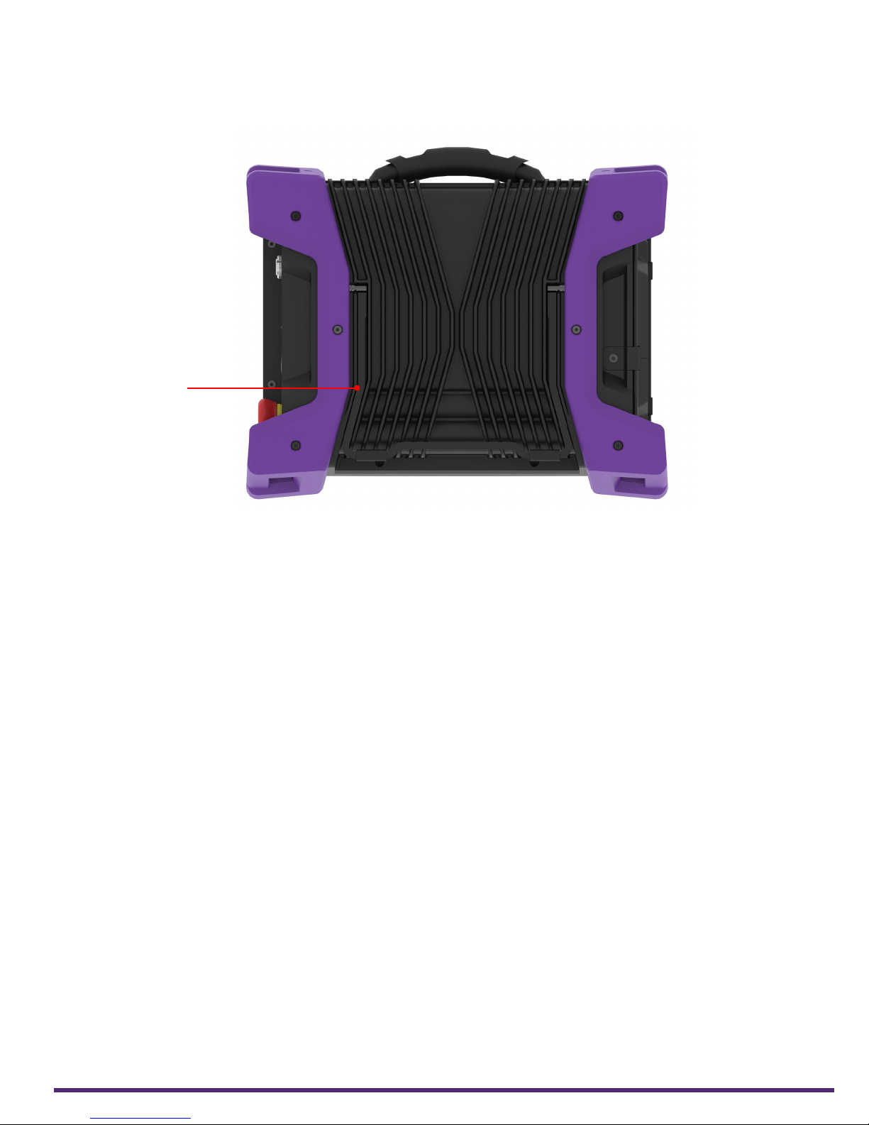
Rear
Figure 1–4 Swift back panel overview
1
Swift Overview
1. Instrument stand
This stand retracts outwards to hold Swift at an angle, preventing the instrument from
falling over horizontally.
| 6
Page 19
Swift Overview
Positioning Swift
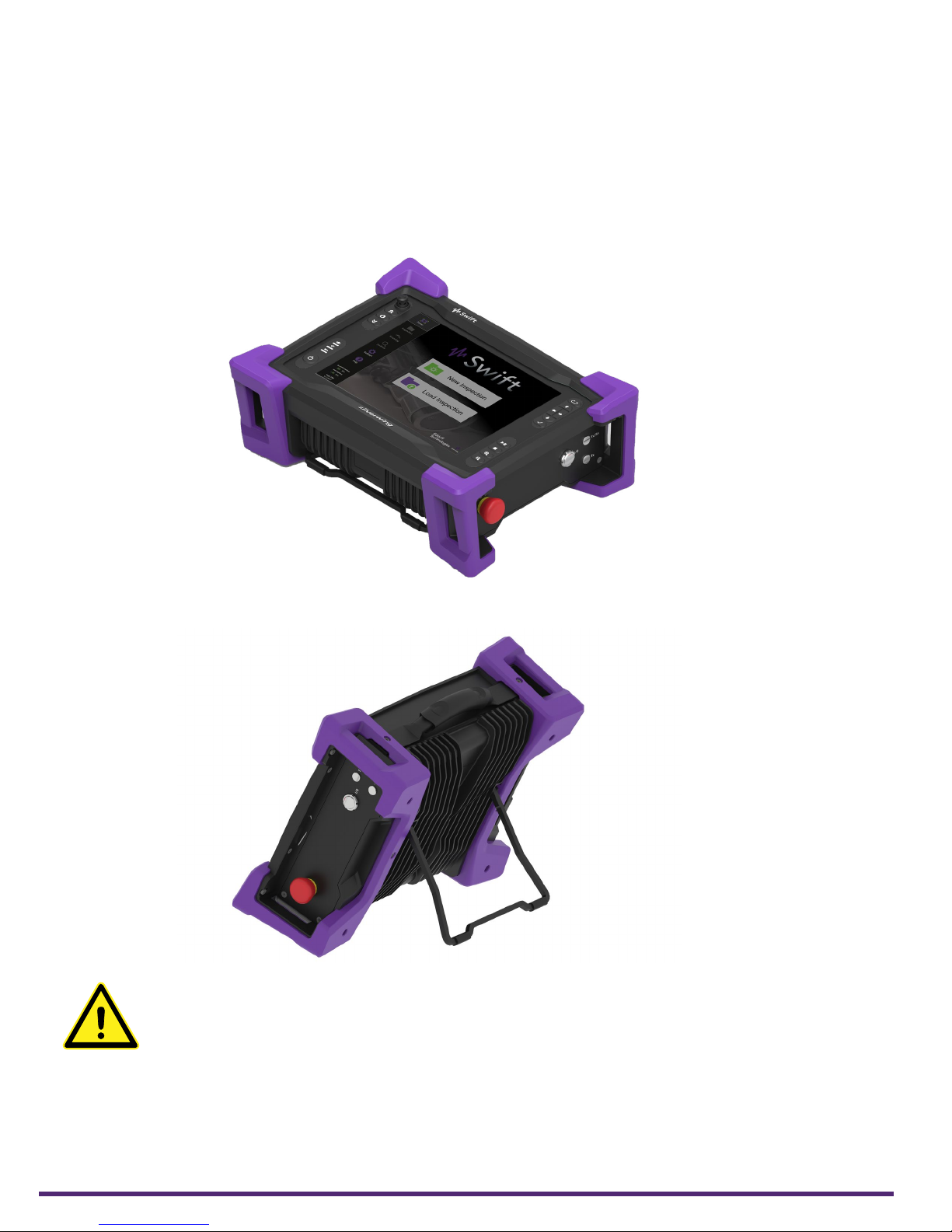
Swift must be properly positioned prior to use so as to reduce the likelihood of the instrument
dropping or falling over. Swift has two safe operating positions, horizontal and tilted. To
use Swift in the tilted position, simply pull out the stand located at the rear of the instrument
until Swift is at the desired angle. See Appendix A if Swift is being used with the optional
harness.
Figure 1–5 Swift in the horizontal position
Figure 1–6 Swift in the tilted position
Caution
It is possible to use Swift whilst placed on its lower bumpers, however this is not a safe
operational position since the instrument may fall over. To operate Swift at an angle, ensure
that the stand located at the rear of the instrument is used.
Important
Regardless of how the instrument is positioned, it must always have a minimum clearance
of 10cm (4in) on all sides of the instrument. Always position the instrument away from heat
sources. This ensures proper heat dissipation while the instrument is in use.
7 | www.silverwingndt.com
Page 20
Starting Swift
Proceed as follows to turn on your instrument or exit the standby mode:
1. Make sure that at least one of the two batteries is inserted into the battery compar tment
of the instrument, or that the instrument is connected to an external power source
using the supplied power cord.
2. Press the power button.
3. The power indicator at the center of the power button lights green.
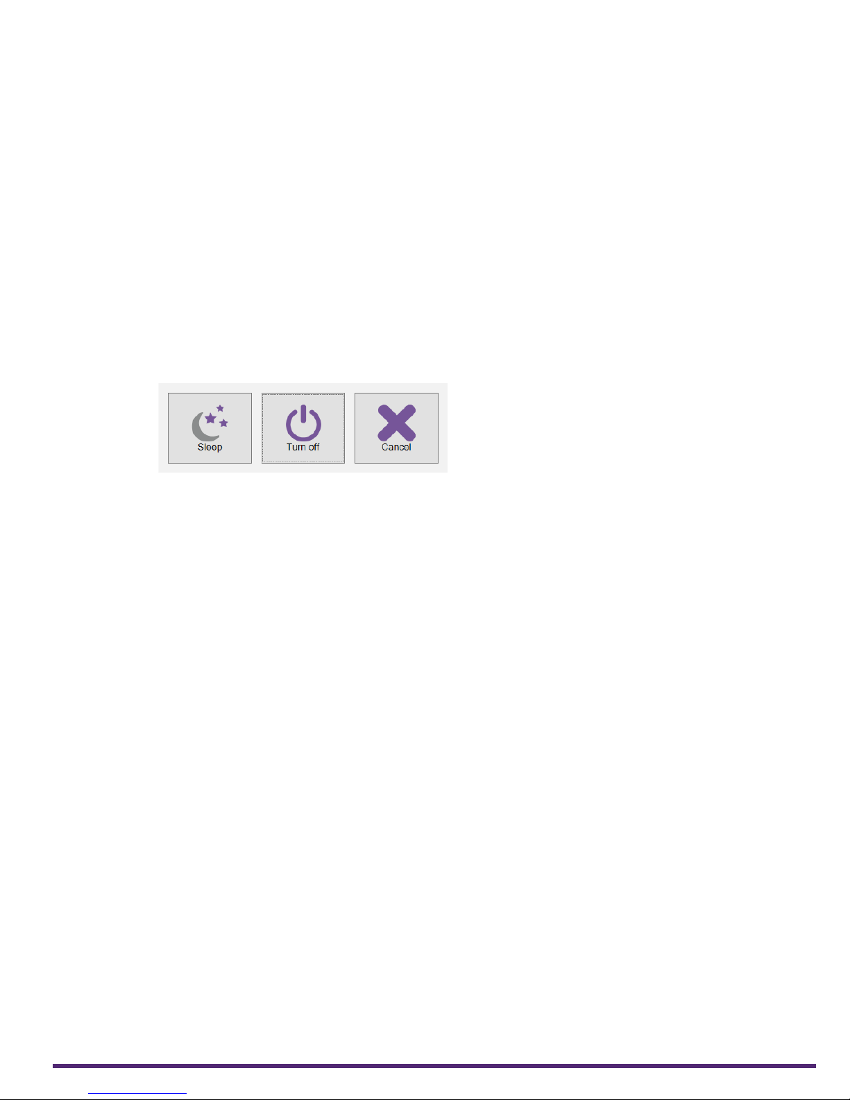
Shutting Down Swift
Proceed as follows to shut down your instrument:
1. Save all your data.
2. Press the power button.
Three option buttons appear on the display.
Figure 1–7 Shutting down Swift
Swift Overview
3. Tap the Turn o.
The instrument shuts down.
| 8
Page 21
Swift Overview
Batteries
Swift can be used under battery power. It is designed with two battery cradles under the
protective battery compartment door, but can be powered by a single battery. Swift uses
Li204SX-7800 lithium-ion rechargeable batteries from Emerging Power, which do not suer
from the memory eect aecting previous generations of batteries. Each battery has an
‘always on’ 5 bar LCD state of change bar graph to indicate estimated remaining battery
life.
WARNING!
When transporting Swift, it is the responsibility of the user to ensure the safety precautions
used are in accordance with the local department of transportation (or equivalent governing
body) rules and regulations.
When carrying or transporting Swift in its transit case, remove the batteries from the
instrument and ensure they cannot come in contact during transport, as this poses a
signicant re and explosion hazard. Swift transit case comes with slots tted to receive
the batteries once removed from the instrument.
Do not replace the batteries for any battery other than Li204X-7800 lithium-ion rechargeable
batteries from Emerging Power
Inserting/Removing Batteries
Inserting Batteries
1. On the left side of Swift, unlatch the battery compartment door, then open.
2. Align your battery with one of the battery cradles.
Note: Battery cradles are marked A and B. If inserting only one battery it does not matter
which cradle is used.
3. Make sure that the battery contacts are facing inward and upward.
4. Slide the battery into the battery cradle until it is fully inserted.
5. Close the battery compartment door and secure the latch.
Removing Batteries
1. On the left side of Swift, unlatch the battery compartment door, then open.
2. Grab the battery tab between thumb and forenger.
3. Pull on the tab to release the battery contacts.
4. Slide the battery out of its cradle.
Hot Swapping Batteries
It is possible to remove one battery from Swift when it is powered on as the instrument can
operate on a single battery. If the power in the remaining battery is insucient to keep
Swift powered on, the instrument shuts down without damaging electronic components.
Any work in progress in Swift software (acquisition, etc.) is lost.
Battery Charging
Swift batteries recharge automatically when they are in the instrument and the AC adaptor
is connected to the power outlet and turned on. The battery indicator on the lower-left
keypad displays information about the battery charge. Swift software also features a
battery charge indicator.
Note: Batteries do not recharge when their internal temperature exceeds 45°C (113°F).
Batteries also do not power Swift when the instrument’s internal temperature exceeds 55°C
(131° F).
9 | www.silverwingndt.com
Page 22
Using the Battery Charger
Note: Swift batteries can also be charged in an external battery charger. This charger
conditions and calibrates the instrument’s batteries, which is important in maximizing
battery life.
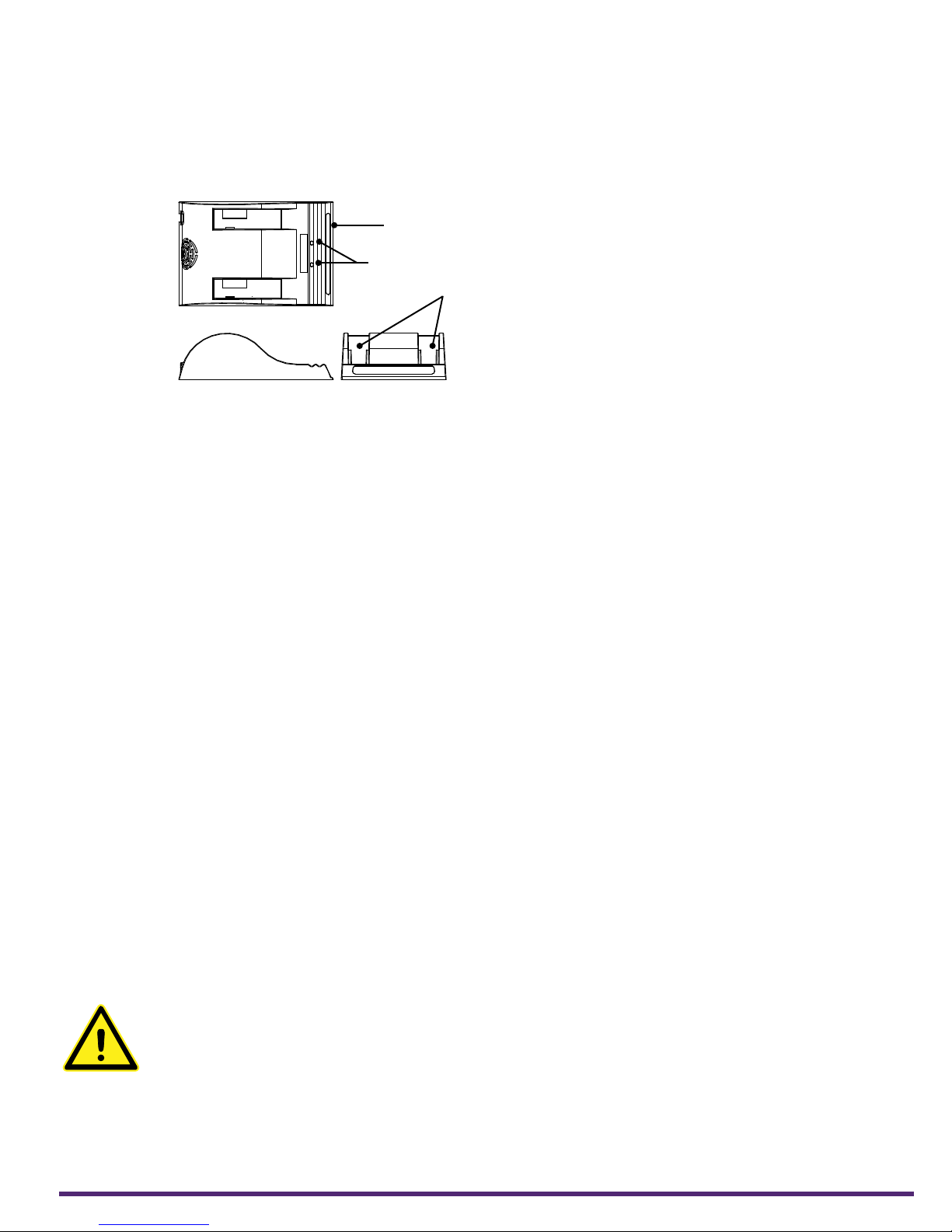
Figure 1–8 Optional battery charger
Status window
Calibration buttons
Battery slots
To charge the batteries with the optional charger:
1. Place the charger on a at and level surface, away from heat and moisture sources.
2. Insert the power supply’s DC connector into the back of the external charger.
3. Connect the power supply to an AC supply using the supplied cable.
All the LEDs ash momentarily to let you know that power is present.
Swift Overview
4. Insert the batteries into the battery slots while making sure that the contacts are fully
seated.
The charger automatically begins charging the batteries and the LEDs in the status
window display the following information:
• Flashing green: battery charging
• Green: battery fully charged
• Flashing blue: battery calibrating
• Blue: battery charge gauge calibrated
• Flashing red: battery charge gauge in need of calibration
• Red: error
Calibrating Batteries
To ensure that your batteries perform at their full capacity for the longest possible time, it
is important to calibrate them on a regular basis. Calibration involves a standard battery
charge followed by a deep discharge, and then a complete charge.
It is recommended that batteries are calibrated every six months. This procedure usually
takes 10 to 13 hours, whereas a standard charge only takes approximately 3.5 hours.
To calibrate batteries, place them in the charger and then press the calibration button.
Storing Batteries
Whenever transporting Swift in its case, remove the batteries from the instrument, place
them in plastic bags and ensure they cannot come into contact during transport since they
pose a signicant re and explosion hazard.
Swift transport case is outtted with two slots intended for the batteries. We recommend
that they are taken advantage of.
| 10
Page 23

Scorpion2 Overview
Chapter 2
Scorpion2 Overview
11 | www.silverwingndt.com
Page 24
Scorpion2 Overview
Introducing Scorpion2
Scorpion2 crawler is designed for B-Scan inspection of ferrous plate ranging from a diameter
of 3 m (10 ft) diameter up to at plate. Scorpion2 is tted with a 5MHz twin crystal dry
coupled wheel probe allowing it to inspect material thickness between 5mm to 100mm
(0.19 in to 3.9 in). The battery powered crawler is motor driven and can scan at speeds of
up to 180 mm/sec (7 in/sec).
Scorpion2 works in conjunction with Swift which provides the Ultrasonic Data Acquisition
software and drive control.
What’s in the Box
Scorpion2 comes with the following standard accessories:
• Two, high-capacity batteries
• Battery charger
• Umbilical
• Umbilical tail and rubber clip
Top View
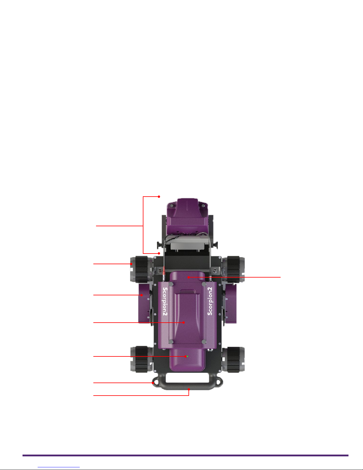
Figure 2–1 Scorpion2 top view
1
2
3
• Silicone oil and syringe
• Metric hex key set
• Circlip pliers and circlips
• Magnetic drive o sheet
8
4
5
6
7
1. Probe head
The probe head at the front of the
crawler is designed to magnetically
adhere to the inspection surface, or
when lifted fully upwards adhere to
the front of Scorpion2 crawler.
2. Magnetic drive wheels
The four drive wheels provide magnetic
attraction to the inspection surface.
Each wheel is independently
controlled, allowing full steering
control over the crawler.
| 12
Page 25
Scorpion2 Overview
3. Encoders
During an automatic mode scan, the
crawler relies on both encoders to
actively steer the crawler. The right
encoder is used to record the distance
travelled in either scanning mode.
4. Battery lid
A sealed battery cover with captive
thumb screws protects the battery
compartment from the elements.
5. LED indicator
This displays the communication state
between Scorpion2 crawler and Swift.
The LED displays the following
information:
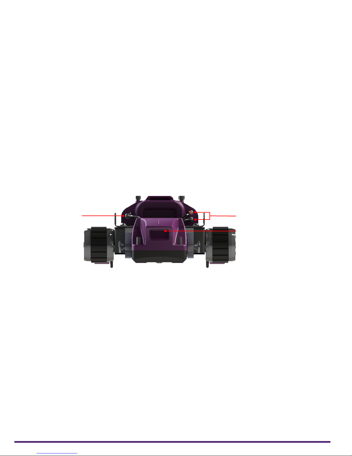
Front View
Figure 2–2 Scorpion2 front view
• Green: Power on and
communication with Swift
• Red flashing: Power on but no
communication with Swift
• O: No power to Scorpion2
6. Umbilical tether
Use this to attach the tether of the
umbilical and avoid unwanted strain
on Scorpion2 connectors.
7. Rear carry handle
Use this to lift and carry Scorpion2
cra w le r.
8. Top carry handle
Use this to lift and carry Scorpion2
cra w le r.
1
1. Wheel Probe linear actuator
connector
Use this connector for the wheel probe
linear actuators found within the
probe head. Linear actuators
automatically lift the wheel probe
away from the inspection surface
when not performing a data
acquisition scan.
2
3
2. Wheel probe UT connectors
Use these connectors for the ultrasonic
transmit and receive connectors of
the wheel probe.
3. Probe head lifting handle
Use this to raise and lower the probe
head.
13 | www.silverwingndt.com
Page 26
Rear View
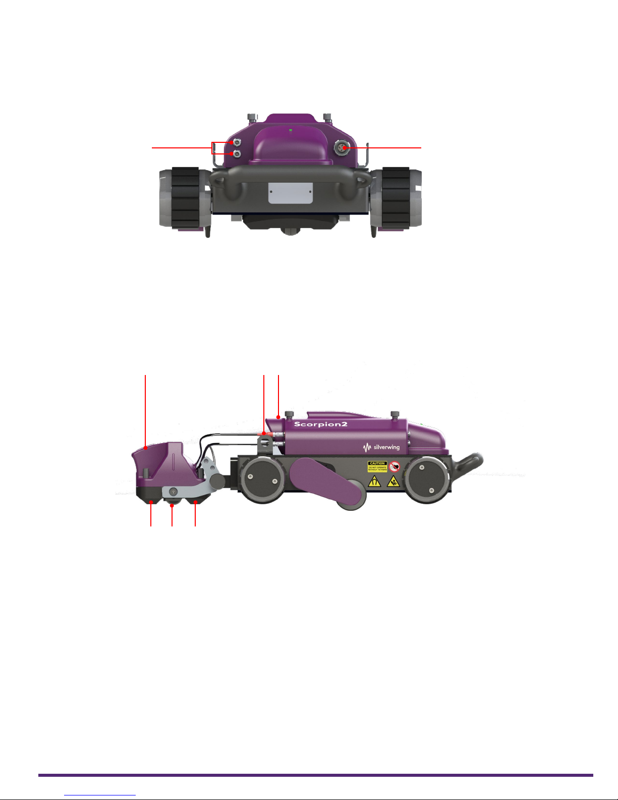
Figure 2–3 Scorpion2 rear view
Scorpion2 Overview
1
1. Umbilical UT connectors
Use these connectors for the ultrasonic
transmission and receiving from Swift.
Side view
Figure 2–4 Scorpion2 side view
1
2
2. Umbilical I/O connector
Use this connector for the
communication with Swift.
4 5
3 2 3
1. Probe head lifting handle
Use this to raise and lower the probe
head.
2. Ultrasonic wheel probe
5MHz twin crystal dry coupled wheel
probe.
3. Wear runners
Removable wear runners that are in
constant contact with the inspection
surface.
4. Tether line attachments
Use these to attach the tether line
during the inspection.
5. Top carry handle
Use this to lift and carry Scorpion2
cra w le r.
| 14
Page 27
Scorpion2 Overview
Batteries
Inserting/Removing Batteries
Scorpion2 uses an NH2054 HD31 14.4V Lithium Ion smart battery from Inspired Energy. Each
battery has an ‘always on’ 5 bar LCD state of change bar graph to indicate estimated
remaining battery life.
WARNING!
When transporting Scorpion2, it is the responsibility of the user to ensure the safety
precautions used are in accordance with the local department of transportation (or
equivalent governing body) rules and regulations.
When transporting Scorpion2 in its transit case, remove the batteries from the crawler and
ensure they cannot come in contact during transport, as this poses a signicant re and
explosion hazard.
Scorpion2 transit case comes with slots, tted to receive the batteries once removed from
the crawler.
Note
Do not replace the batteries for any battery other than NL2054 HD31 Lithium-Ion batteries
from Inspired Energy.
Inserting Batteries
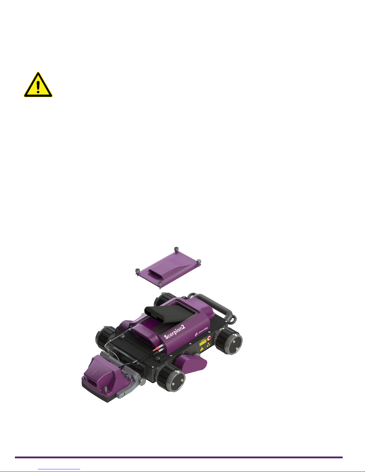
1. On the lid of Scorpion2, unscrew the four thumb screws and remove the battery
compartment lid.
2. Make sure that the battery contacts are facing inwards and downwards.
3. Secure the battery compartment lid using the thumb screws.
Figure 2–5 Scorpion2 inserting batteries
Removing Batteries
1. On the lid of Scorpion2, unscrew the four thumb screws and remove the battery
compartment lid.
2. Grab the battery tab between thumb and forenger then pull upwards to release.
15 | www.silverwingndt.com
Page 28
Scorpion2 Overview
Battery Charging
Scorpion2 batteries must be charged using the external battery charger. This charger
conditions and calibrates the instrument’s batteries, which is important to maximize their
lives. We recommend calibrating the batteries every six months.
Figure 2–6 Battery charger
Status window
Calibration buttons
Battery slots
To charge the batteries with the charger:
1. Place the charger on a at and level surface, away from heat and moisture sources.
2. Insert the power supply’s DC connector into the back of the external charger.
3. Connect the power supply to an AC supply using the supplied cable.
All the LEDs ash momentarily to let you know that power is present.
4. Insert the batteries into the battery slots while making sure that the contacts are fully
seated.
The charger automatically begins charging the batteries and the LEDs in the status
window display the following information:
• Flashing green: battery charging
• Green: battery fully charged
• Flashing blue: battery calibrating
• Blue: battery charge gauge calibrated
• Flashing red: battery charge gauge in need of calibration
• Red: error
Calibrating Batteries
To ensure that your batteries perform at their full capacity for the longest possible time, it
is important to calibrate them on a regular basis. Calibration involves a standard battery
charge followed by a deep discharge, and then a complete charge.
It is recommended that batteries are calibrated every six months. This procedure usually
takes 10 to 13 hours, whereas a standard charge only takes approximately 3.5 hours.
To calibrate batteries, place them in the charger and then press the calibration button.
Storing Batteries
WARNING
Whenever transporting Scorpion2 in its case, remove the battery from the crawler, place
them in plastic bags and ensure they cannot come into contact during transport since they
pose a signicant re and explosion hazard.
Scorpion2 transport case is outfitted with two slots intended for the batteries. We
recommend that they are taken advantage of.
| 16
Page 29
Scorpion2 Overview
Handling Scorpion2
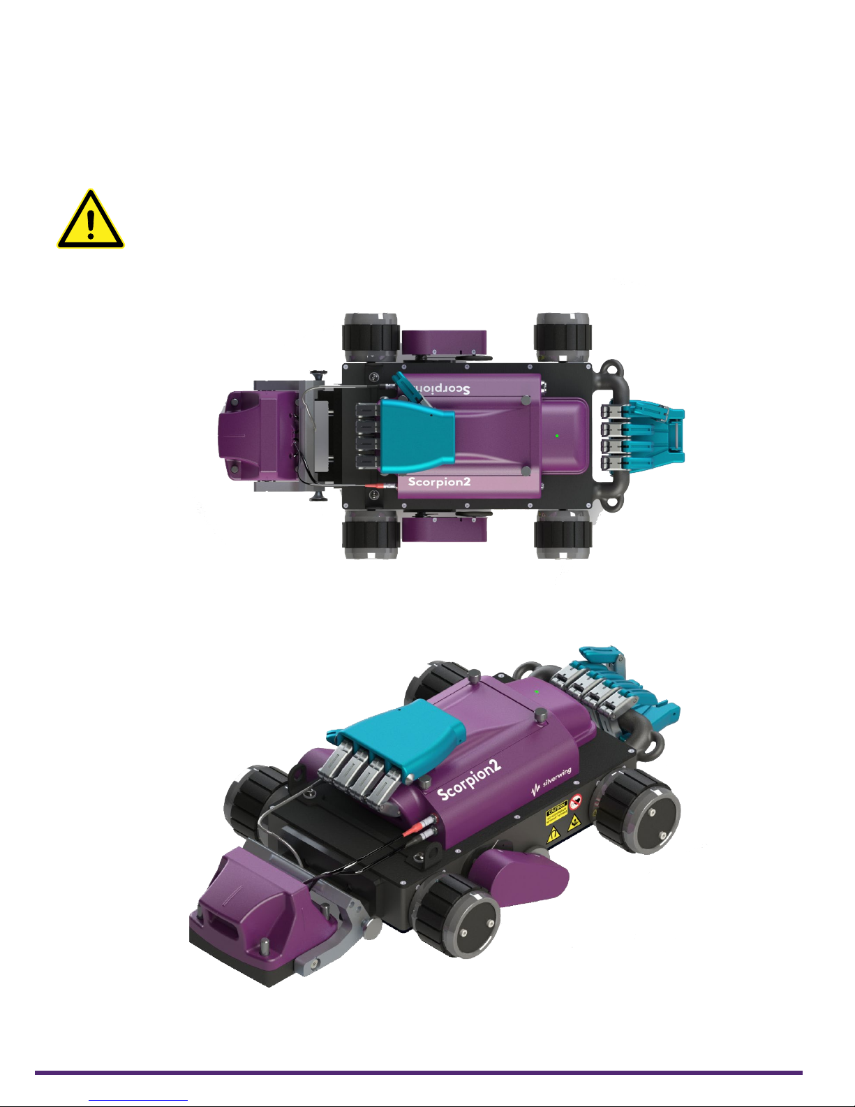
The weight of Scorpion2 unit is 10.5 kg (23 lb). Only lift and carry the crawler using the
handles integrated into its body, located on the top of the crawler and at it’s rear. Before
carrying the crawler, ensure the probe head has been fully lifted upwards and is adhered
to the front of Scorpion2.
WARNING!
Care must be taken when handling Scorpion2, due to the magnetic pull from the wheels
and probe holder.
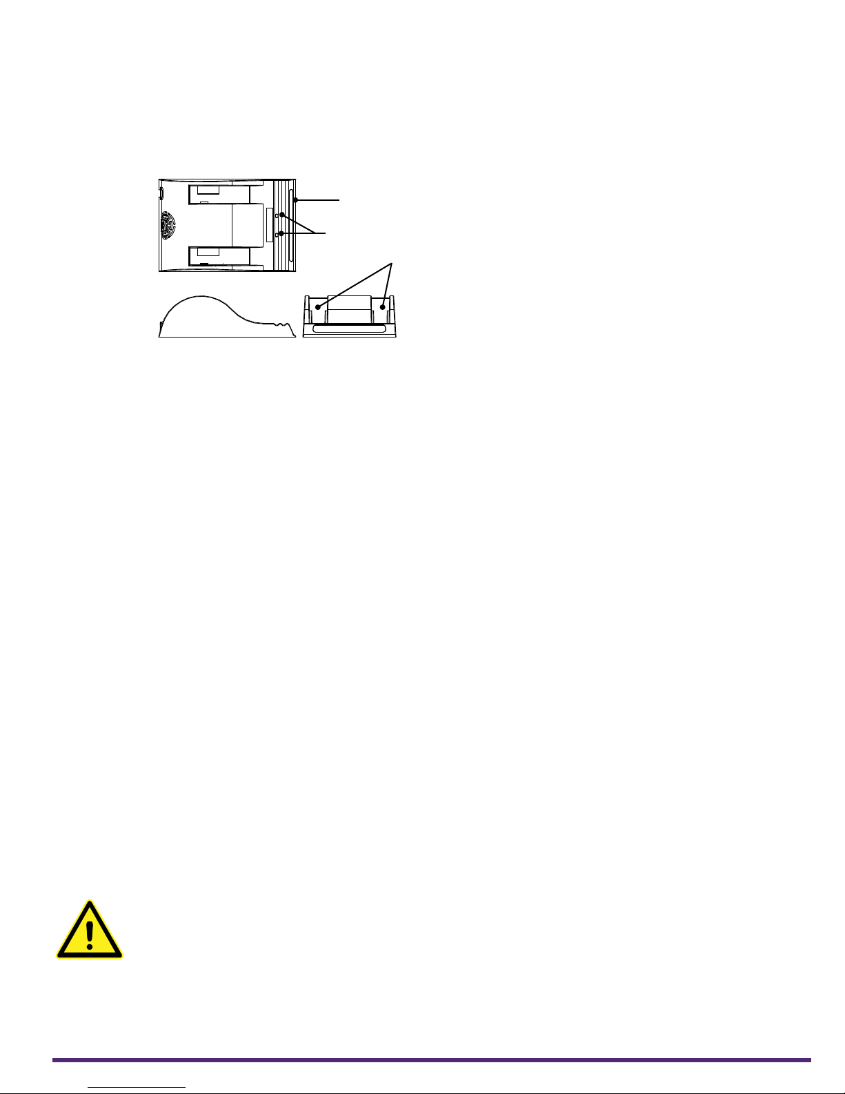
Figure 2–7 Scorpion2 handling top view
Figure 2–8 Scorpion2 handling isometric view
17 | www.silverwingndt.com
Page 30
Scorpion2 Overview
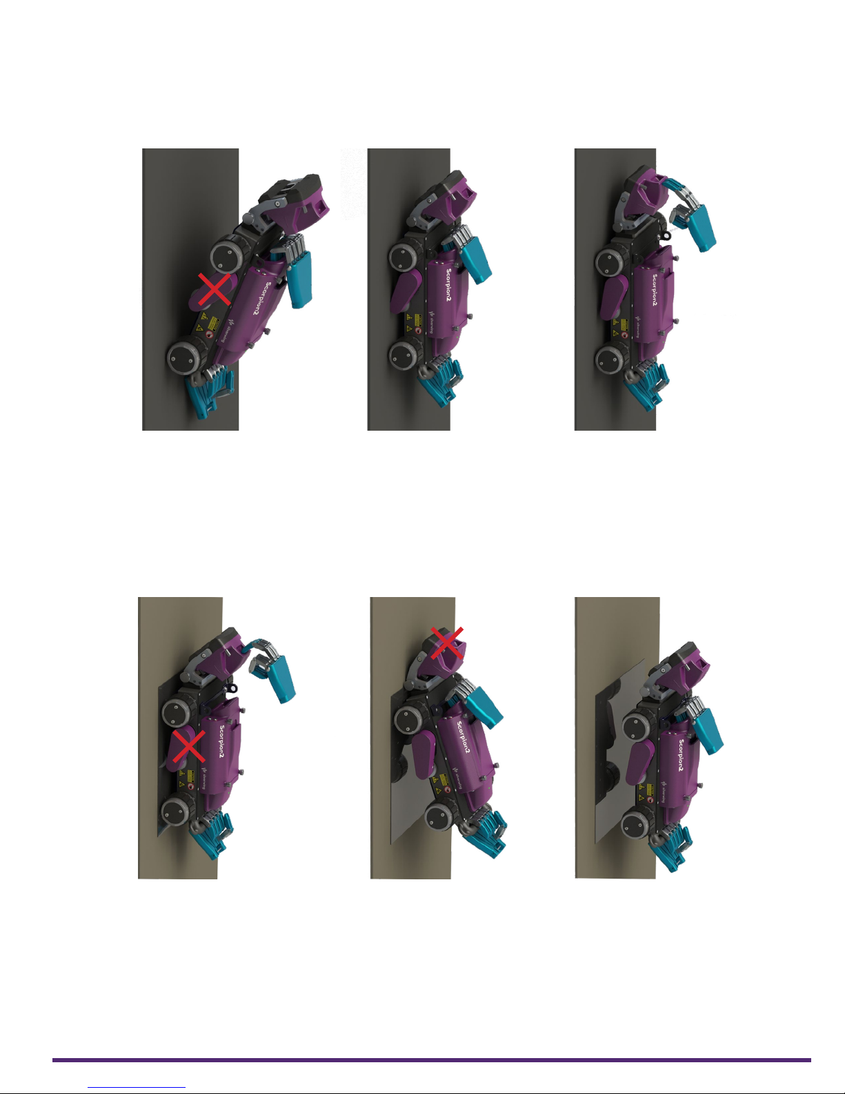
Deploying Scorpion2 onto the Inspection Surface
Pick up the crawler using the correct handles.
Figure 2–9 Deploying Scorpion2
1. Slowly lower the rear wheels of the crawler onto the inspection surface.
2. Slowly lower the front wheels of the crawler onto the inspection surface.
3. Place the probe holder onto the inspection surface.
Removal of Scorpion2 from the Inspection Surface
To remove the crawler from the inspection surface:
Figure 2–10 Removing Scorpion2 from the inspection surface.
1. Place the magnetic drive o pad onto the inspection surface then drive the crawler on
to it.
2. Lift the probe head fully upwards away, from the inspection surface.
3. Holding the crawler by the two handles, pull the rear handle away to lift the rear
wheels from the inspection surface.
4. Continue until the front wheels lift away from the inspection surface.
5. Use the top handle to pull the crawler away from the inspection surface.
6. Retrieve the magnetic drive o pad.
| 18
Page 31

Scorpion2 Overview
Use of the Umbilical Tail
The umbilical tail is designed to keep the umbilical cable clear of the crawler especially
when the crawler is driven down a vertical inspection surface. The tail attaches to the rear
carry handle of the crawler.
To t the umbilical tail to Scorpion2:
1. Feed the tail up through the bottom of the rear carry handle, then clip it onto the carry
handle.
2. Use the black rubber clamp to secure the umbilical cable to the top of the tail.
To remove the umbilical tail from Scorpion2:
1. Release the black rubber clamp.
2. Lift the tail upwards and remove from the rear carry handle.
19 | www.silverwingndt.com
Page 32

Software Overview
Chpter 3
Software Overview
20 | www.silverwingndt.com
Page 33

Software Overview
Introducing Swift Software
Running on Swift is a powerful, easy-to-use data acquisition and analysis software. It is
specically designed for B-Scan ultrasonic inspections and relies on an intuitive wizard to
congure setups.
The software benets from a graphical user interface (GUI) designed to simplify the
inspection process. The multi-touch display is the best way of interacting with Swift,
however a USB mouse can keyboard can be connected, if required.
On the left hand side of the GUI is a sidebar that provides access to the various windows
associated with the setup and progression of an inspection, the inspection setting
preferences and status information regarding Swift. A toolbar menu with window specic
operational buttons is located at the top of the GUI.
Home
Home allows either a new inspection to be created or a saved inspection on Swift to be
loaded.
Figure 3–1 Home view
3
4
5
1. New Inspection
Tap this button to access the Inspection Details window.
2. Load Inspection
Tap this button to load an existing inspection saved on Swift.
3. Joystick Status
This indicates the joystick status of Swift.
4. Battery Status
The icons indicate the current battery level of Swift and, when connected, Scorpion2.
5. Time and Date
This displays the current time and date.
1
2
| 21
Page 34
Software Overview
Inspection
Load Inspection
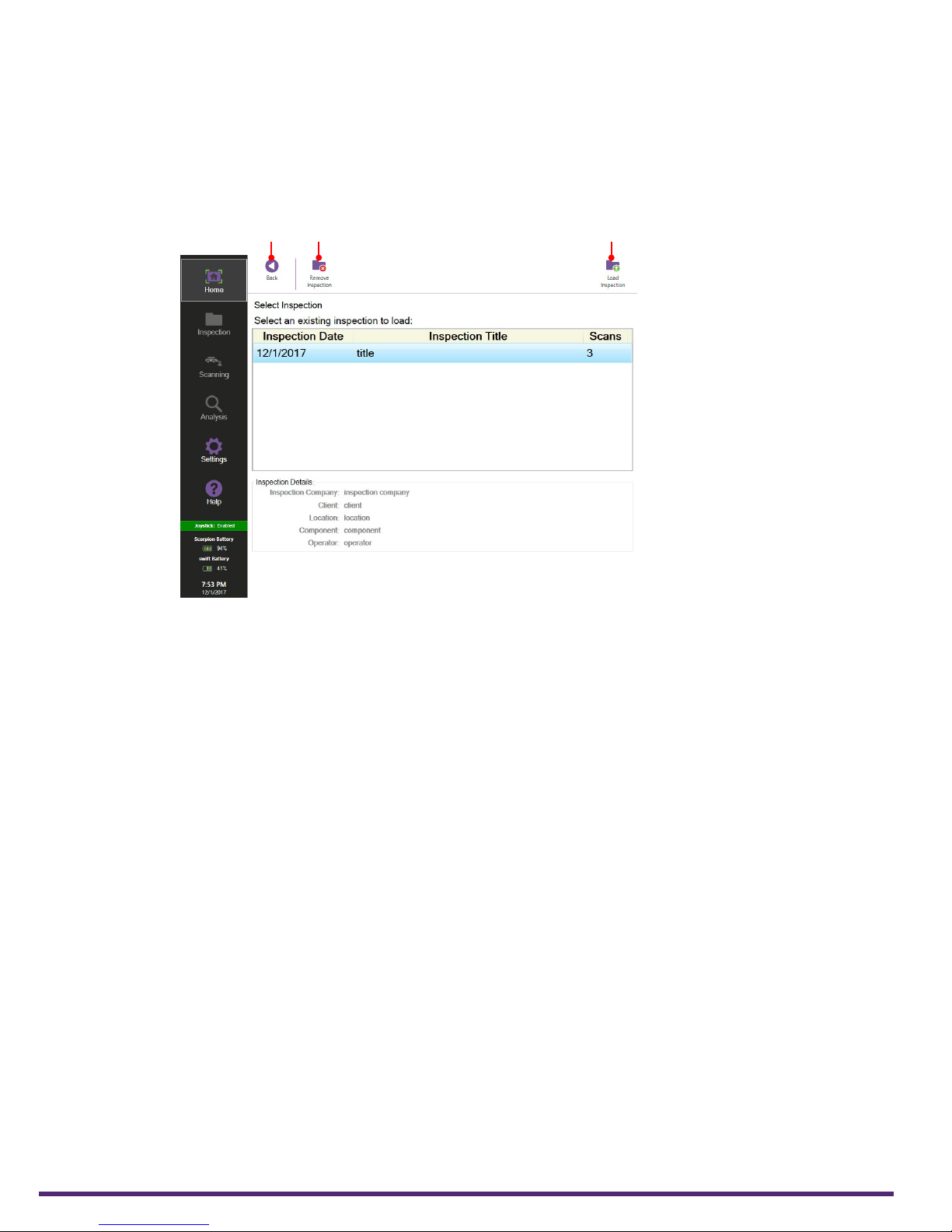
The Inspection window lists inspections already stored on Swift, details relating to the
inspection and the number of scans conducted within the inspection.
Figure 3–2 Inspection window
1 2 3
1. Back
Tap this button to return to the Home window.
2. Remove Inspection
Tap this button to delete a selected inspection.
3. Load Inspection
Tap this button to load a selected inspection.
22 | www.silverwingndt.com
Page 35
Software Overview
Inspection Details Window
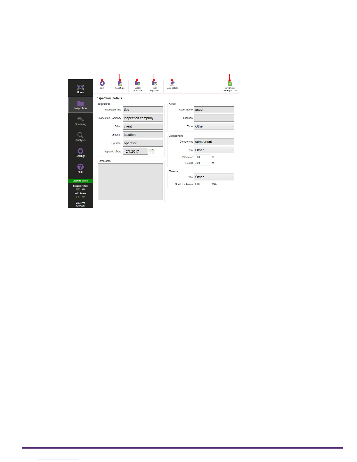
Inspection Details allows information relating to the inspection, the asset, component and
material under test to be entered or modied.
Figure 3–3 Inspection details window
1 2 63 4 5
1. Back
Tap this button to return to the Home window.
2. Load Scan
Tap this button to analyse a scan saved within the current inspection.
3. Export Inspection
Tap this button to export the current inspection to a USB drive in a CMAP compatible
form at (CMX).
4. Finish Inspection
Tap this button to nish the current inspection.
5. Clear Details
Tap this to clear all current inspection details.
6. Save Details and Begin Scan
Tap this in order to progress to the setup for scanning.
| 23
Page 36
Software Overview
Acquisition Device window
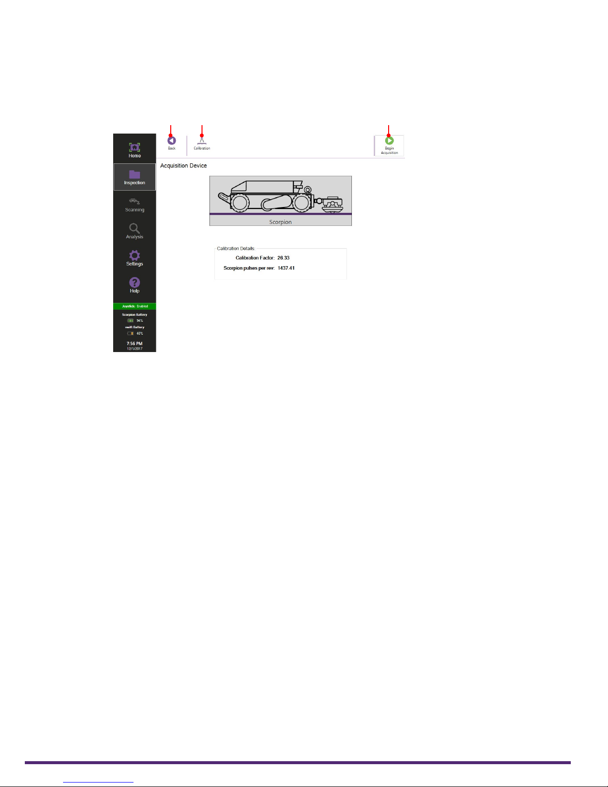
Acquisition Device contains the setup and calibration details of the encoders for Scorpion2
cra w le r.
Figure 3–4 Acquisitions device window
1 2 3
1. Back
Tap this button to return to the Home window.
2. Calibration
Tap this button to access the encoder calibration setup.
3. Begin Acquisition
Tap this button to progress to the Acquisition B-Scan window.
24 | www.silverwingndt.com
Page 37
Software Overview
Scanning
Acquisition: B-Scan window
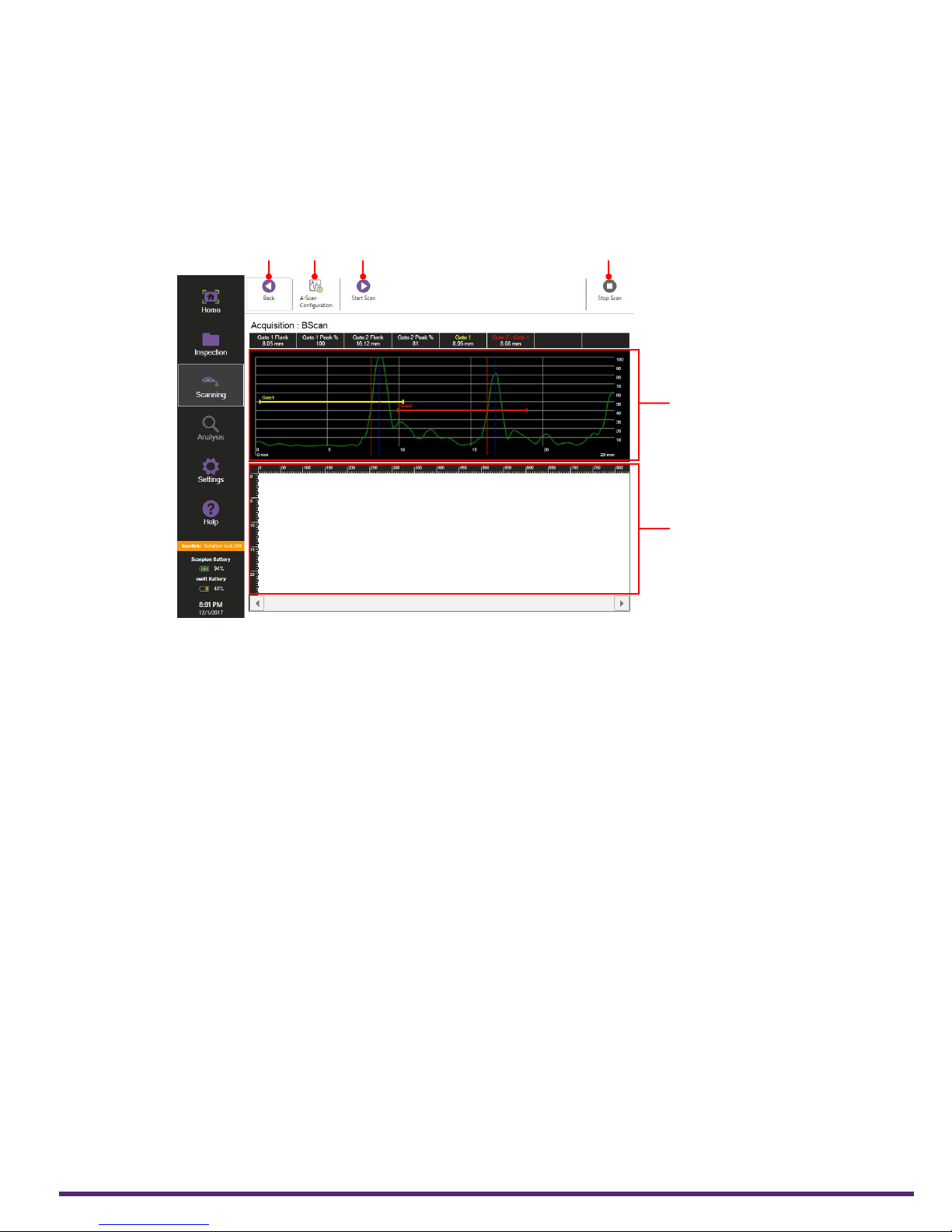
Acquisition B-Scan allows setup of the A-Scan conguration and scanning parameters for
data acquisition. During data capture, live views for both A-Scan and B-Scan traces are
shown along with the scan controls for the acquisition device.
Figure 3–5 Acquisition: B-Scan window
1 2 43
5
6
1. Back
Tap this button to return to the Acquisition Device window.
2. A-Scan Conguration
Tap this button to access the A-Scan Conguration window.
3. Start Scan
Tap this button to progress onto the selection of either Automatic or Manual mode.
4. Stop Scan
Tap this button to nish the scan and progress to data analysis and saving.
5. A-Scan view
The A-Scan signal captured by the acquisition device is viewed along with gate positions.
The horizontal axis is time base and the vertical axis is signal amplitude.
6. B-Scan view
This area displays the B-Scan inspection data captured by the acquisition device. The
horizontal axis is distance and vertical axis is thickness.
| 25
Page 38
Software Overview
Toolbar During Automatic Scan
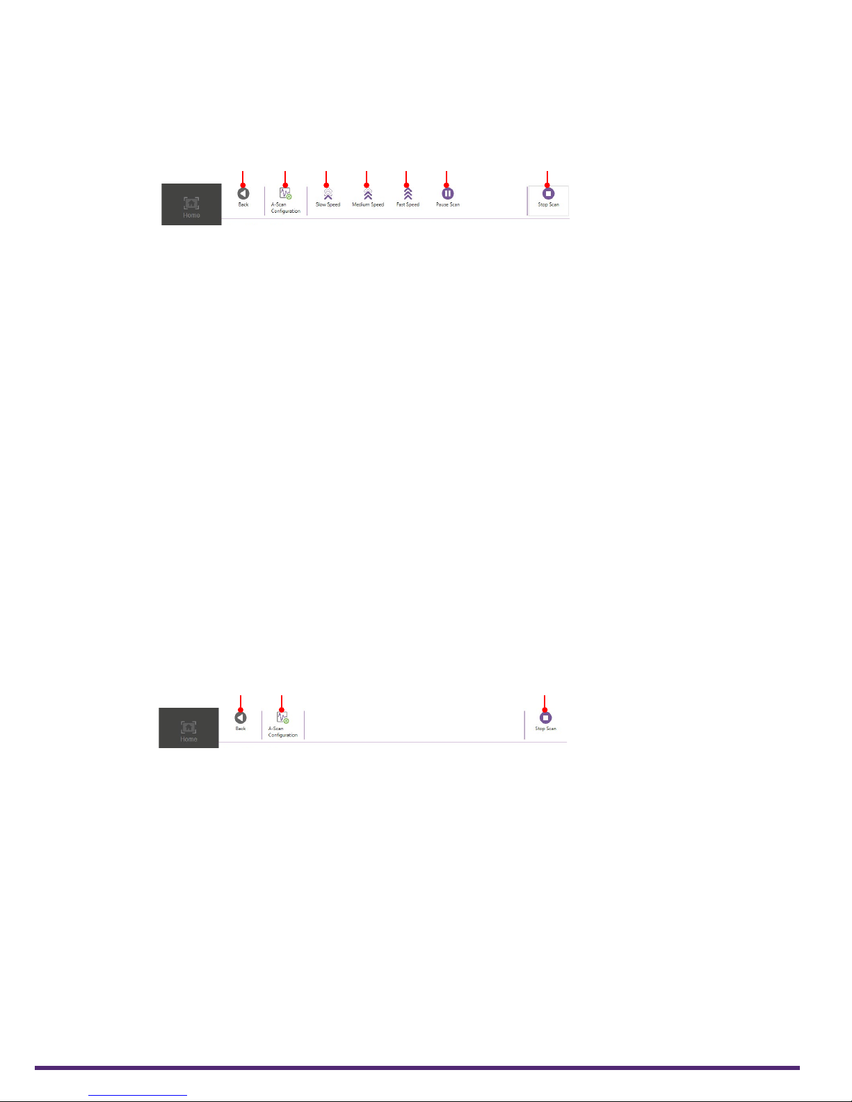
During a scan in automatic mode, the toolbar menu displays the following options:
Figure 3–6 Automatic scan toolbar
1 2 73 4 5 6
1. Back
Not available.
2. A-Scan Conguration
Tap this button to access the A-Scan Conguration window.
3. Slow Speed
Tap this button to drive at a slow scanning speed.
4. Medium Speed
Tap this button to drive at a medium scanning speed.
5. Fast Speed
Tap this button to drive at a fast scanning speed.
6. Pause Scan
Tap this button to pause the scan.
7. Stop Scan
Tap this button to end the scan and progress to the data analysis and saving window.
Toolbar During Manual Scan
During a scan in manual mode the toolbar menu displays the following options:
Figure 3–7 Manual scan toolbar
1 2 3
1. Back
Not available
2. A-Scan Conguration
Tap this button to access the A-Scan Conguration window.
3. Stop Scan
Tap this button to end the scan and progress to the data analysis and saving window.
26 | www.silverwingndt.com
Page 39
A-Scan Conguration window
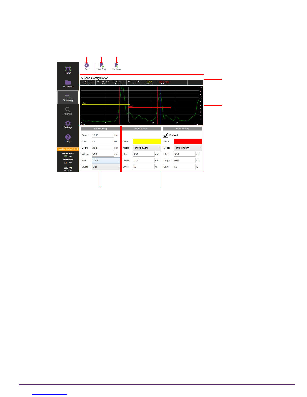
A-Scan conguration window provides access to the ultrasonic and gate setup.
Figure 3–8 A-Scan conguration window
1 2 3
4
5
Software Overview
6 7
1. Back
Tap this button to return to the previous window.
2. Load Setup
Tap this button to load a saved setup.
3. Save Setup
Tap this button to save the existing setup.
4. Gate Information
Information regarding the gate readings and thickness measurements.
5. A-Scan Display
The A-Scan signal captured by the acquisition device is viewed along with gate positions.
The horizontal axis is time base and the vertical axis is signal amplitude.
6. A-Scan Setup
Here, the ultrasonic parameters can be set accordingly.
To adjust Range, Gain, Delay or Velocity tap the desired option and enter a value using
the number pad or use the directional arrows on Swift by altering the step/pre-set
settings, then adjusting accordingly.
Set Filter to match the frequency of the transducer tted to the acquisition device.
Set Crystal to match the transducer tted to the acquisition device.
7. Gate Setup
Two gates are available in Swift software and are used to display thickness
measurements.
Gate 1 is always active by default. To activate gate 2, tap Enabled.
| 27
Page 40
Software Overview
Analysis B-Scan window
Gates are identied by their color. To change a gate color, tap the Color box relating
to that gate then select a color. Tap the Mode button to set the trigger of a gate to
either the Flank (left edge) of the rst signal after the start of the gate, Flank Floating
so that it tracks vertically with the echo amplitude, or the Peak measurement within
the gate.
To set the Start, Length and Level of a gate tap the desired option and enter a value
using the number pad or use the directional arrows on Swift by altering the step/preset settings then adjusting accordingly. Start alters the start position of the gate
relative to the screen. Length sets the width of the gate and Level sets the trigger
threshold of the gate. For Peak and Flank gates, this level corresponds to the vertical
height on the A-Scan trace. For Flank Floating gates the level corresponds to the
amplitude of the tracked signal.
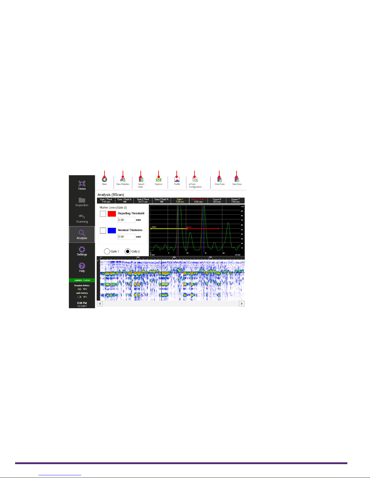
Analysis B-Scan contains various tools for conducting data analysis of a saved scan.
Figure 3–9 Analysis B-Scan window
1 2 83 4 5 6 7
1. Back
Not available
2. View Statistics / View Marker Lines
Tap this button to switch between the statistical information and view marker line tool
for the desired gate.
3. Export Scan
Tap this button to access the Export Scan window where the scan can be exported as
a CSV le to a USB drive.
4. Capture
Tap this button to access the Capture Scan window where the current A-Scan and
B-Scan views can be exported as image les to a USB drive.
5. Prole / Amplitude
Tap this button to switch the B-Scan view between the amplitude and prole views.
The prole view is based on the selected gate option.
28 | www.silverwingndt.com
Page 41
Software Overview
6. A-Scan Conguration
Tap this button to access the A-Scan Conguration window.
7. Close Scan
Tap this to close the scan and exit the Analysis window.
8. Save Scan
Tap this to save the scan and exit the Analysis window.
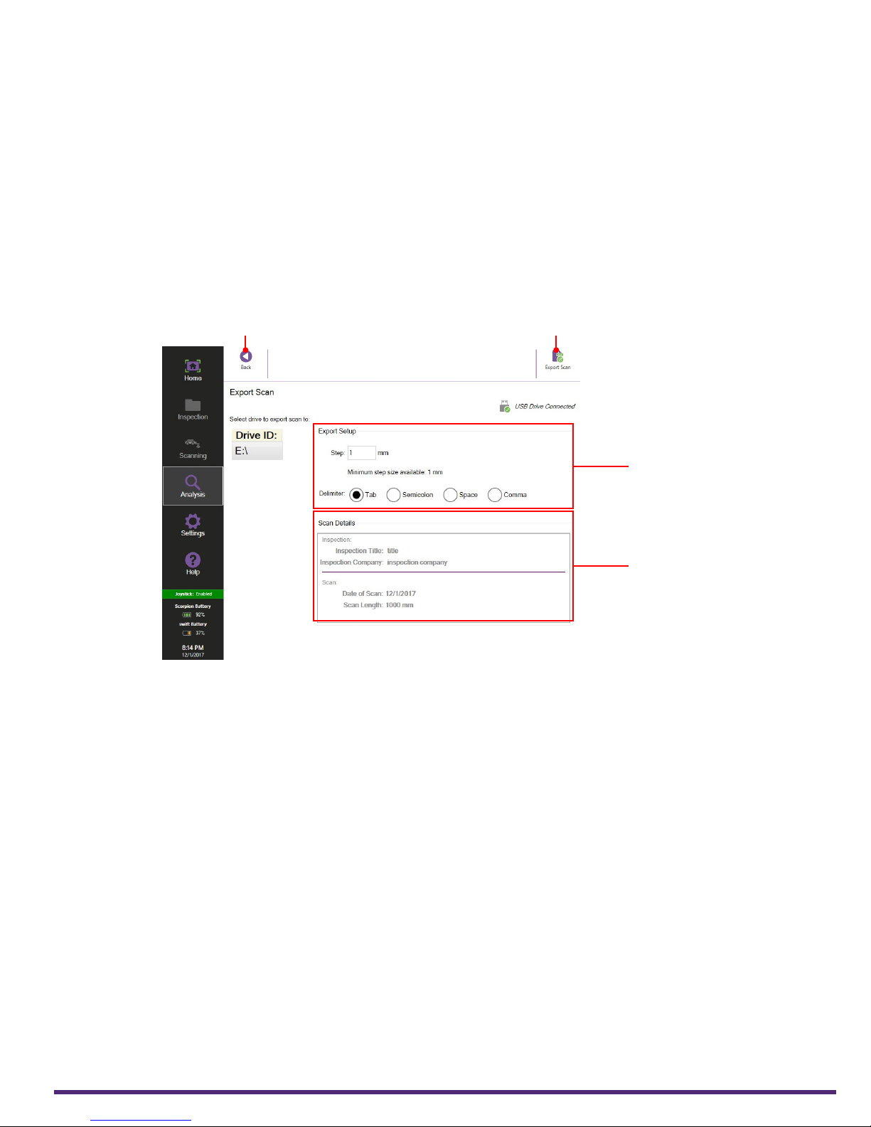
Export Scan window
Export Scan allows the scan to be exported as a CSV le onto a USB drive. Before the scan
can be exported, a USB drive must be connected to Swift.
Figure 3–10 Export scan Window
1 2
1. Back
Tap this button to return to the previous window.
2. Export Scan
Tap this to export the scan onto a USB drive.
3. Export Setup
Set the require step for data export and select the CSV delimiter symbol.
4. Scan Details
Displays information relating to the specic scan.
3
4
| 29
Page 42
Software Overview
Capture Scan Image window
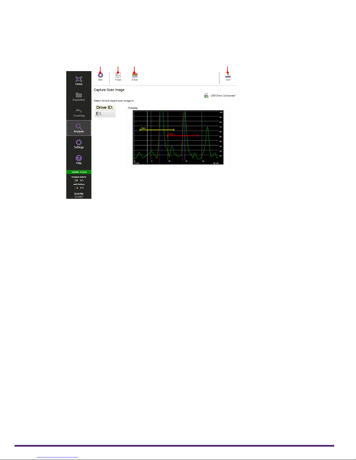
Capture Scan allows an image of either an A-Scan or B-Scan to be saved onto a USB drive.
Figure 3–11 Capture scan Window
1 2 3 4
1. Back
Tap this button to return to the previous window.
2. A-Scan
Tap this to select the A-Scan image at the cross hair position. A preview of the image
is displayed.
3. B-Scan
Tap this to select the B-Scan image. A preview of the image is displayed.
4. Save
Tap this to save the image onto a USB drive.
30 | www.silverwingndt.com
Page 43
Software Overview
Save Scan
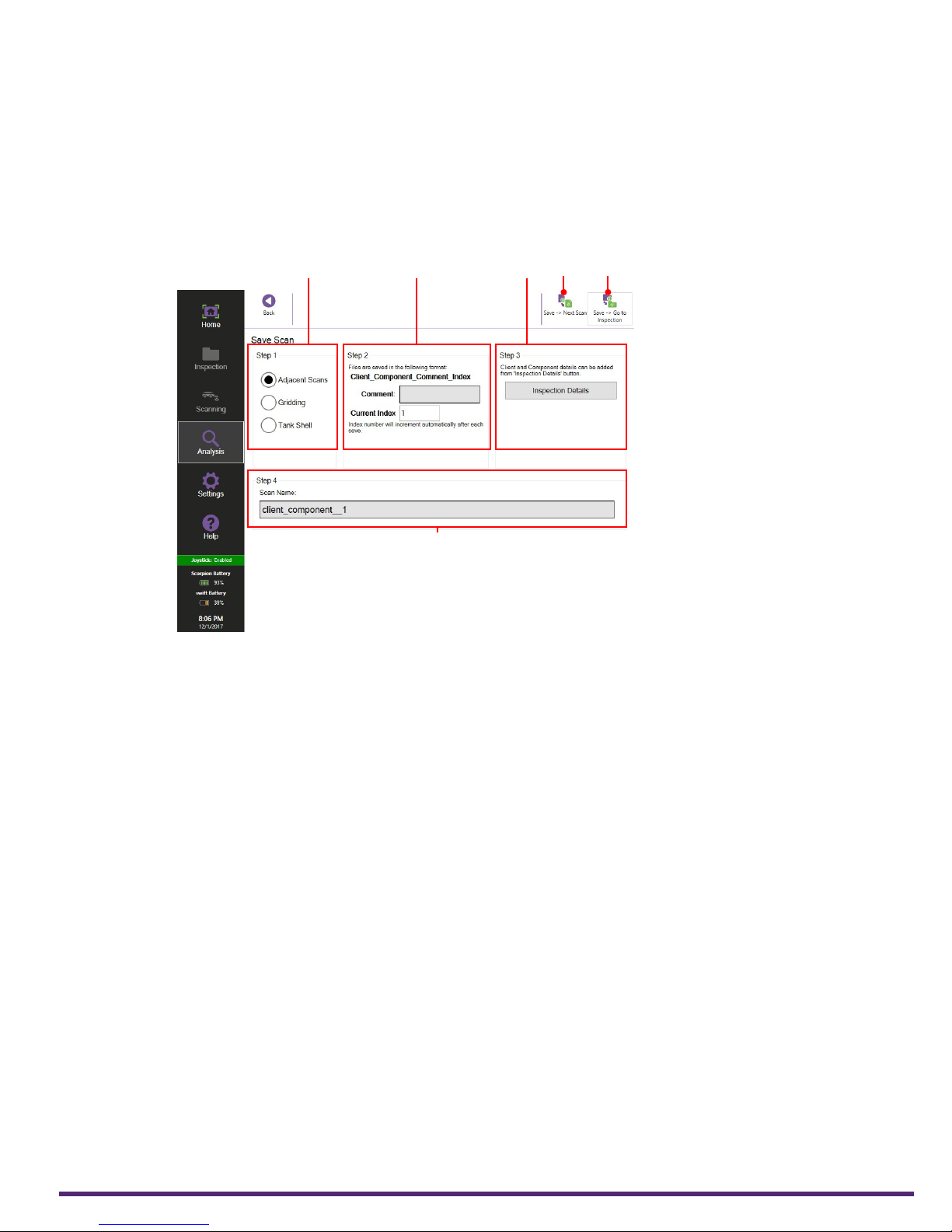
The Save Scan window allows a scan to be saved as either adjacent scan, gridding or tank
shell format, and is split into 4 steps. Adjacent Scans saves scans in a sequential number,
Gridding saves scans in a row and column format with a separation value and Tank Shell
option saves scans in scan, scan separator and course format. The le name and numbering
is created automatically using the entered inspection details and the numbering from the
inspection mode details. Scan numbering increases sequentially.
Figure 3–12 Save scan window
5 61 2 3
4
1. Step 1
Tap the required save mode for the inspection.
2. Step 2
The save options change depending upon which option is selected in Step 1.
3. Step 3
Tap here to open the Inspection Details window. Changing the Client or Component
eld changes the name of the scan le.
4. Step 4
Displays the scan name of the scan to be saved. If required, tap in the box to change
the le name.
5. Save->Next Scan
Tap this button to save the current scan and return to the Acquisition B-Scan window.
6. Save -> Go to Inspection
Tap this button to save the current scan and return to the Inspection Details window.
| 31
Page 44
Software Overview
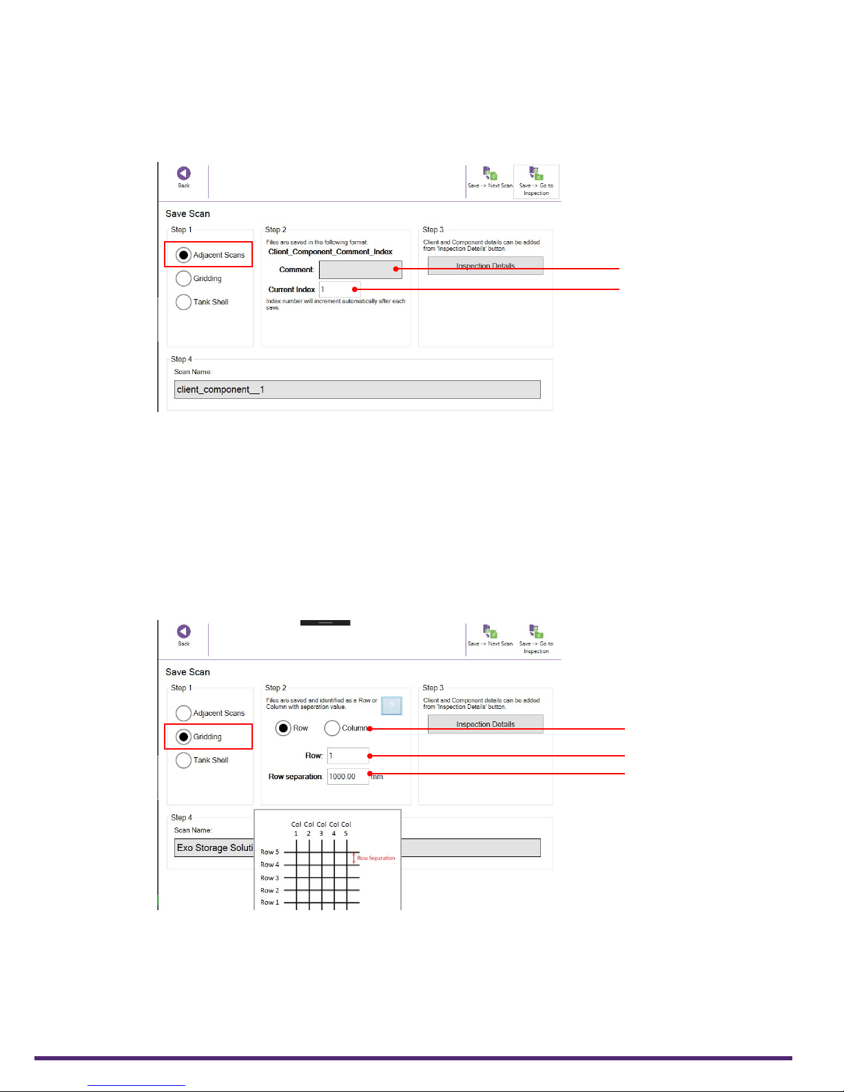
Adjacent Scans
This option saves scans using a number index which increases sequentially after each saved
scan. The le name appears in the format: client_component_comment_index
Figure 3–13 Adjacent scan save options
1
2
1. Comment
Tap here to add a comment which appears as part of the le name.
2. Current Index
This is the number the scan is saved as.
Gridding
This option saves the scans in a row or column format with a separation value. After each
saved scan, the rows, or columns, value increases sequentially.
Figure 3–14 Gridding scan save options
1
2
3
1. Scan Save Format
Select either Row or Column option
2. Row / Column Number
This is the row or column number the scan is saved as.
3. Row / Col Separator
This is the distance between each row or column.
32 | www.silverwingndt.com
Page 45
Software Overview
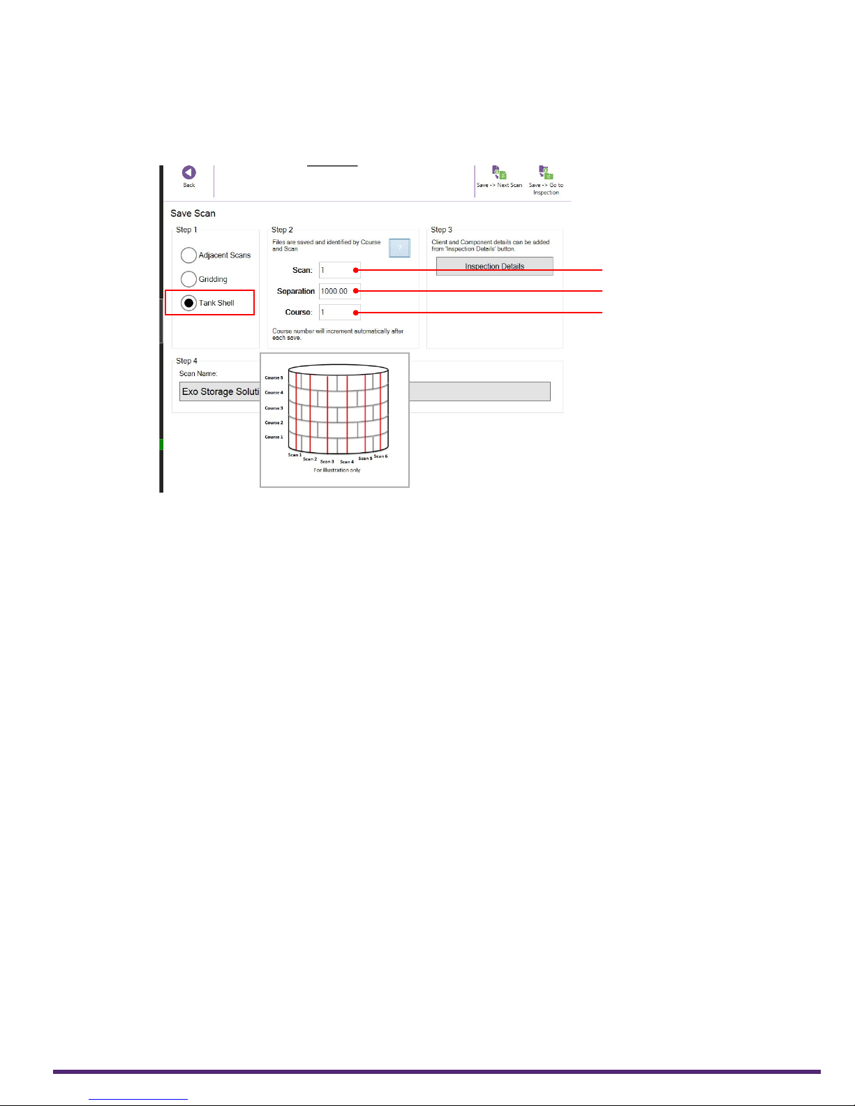
Tank Shell
This option saves scans in a scan and course format. After each saved scan, the course
number increases sequentially.
Figure 3–15 Tank shell save options
1
2
3
1. Scan
This refers to the scan number being conducted on the tank shell.
2. Separation
This is the distance between each scan.
3. Course
This refers to the course number of the tank shell being scanned.
| 33
Page 46
Software Overview
Settings
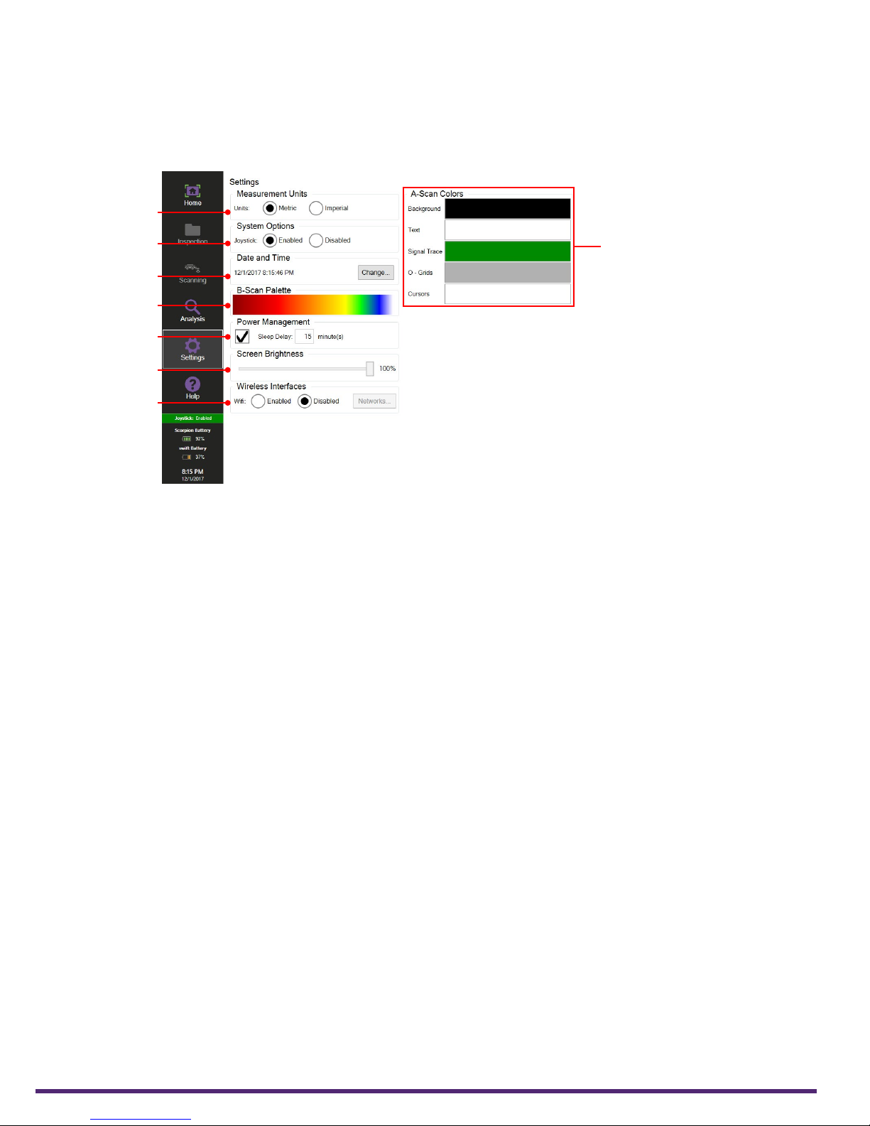
1
Settings contains the options for the inspection measurement units, color options relating
to the A-Scan and B-Scan and conguration settings for Swift.
Figure 3–16 Settings view
2
3
4
5
6
7
1. Measurement Units
Sets the units of measurement for Swift to be either metric ‘mm’ or imperial ‘inches’.
2. System Options
Sets the functionality of the joystick on Swift.
3. Date and Time
Sets the date and time for Swift.
4. B-Scan Palette
Sets the amplitude B-Scan color palette view from pre-dened options.
8
5. Power Management
When active, you can congure a sleep time of 1 to 30 minutes. By default, the sleep
time is 15 minutes.
Power Management turns o the display and the power LED goes from green to red.
Swift goes into sleep mode when the touchscreen and keypad buttons (except the
power button) are idle for the Sleep Delay period.
To exit the sleep mode, quickly press the power button, touch the display, or press any
of the other keypad buttons.
6. Screen Brightness
Set the screen brightness level of Swift.
7. Wireless Interface
Set the functionality of the Wi-Fi on Swift.
8. A-Scan Colors
Set the color for the various options in the A-Scan display.
34 | www.silverwingndt.com
Page 47
Software Overview
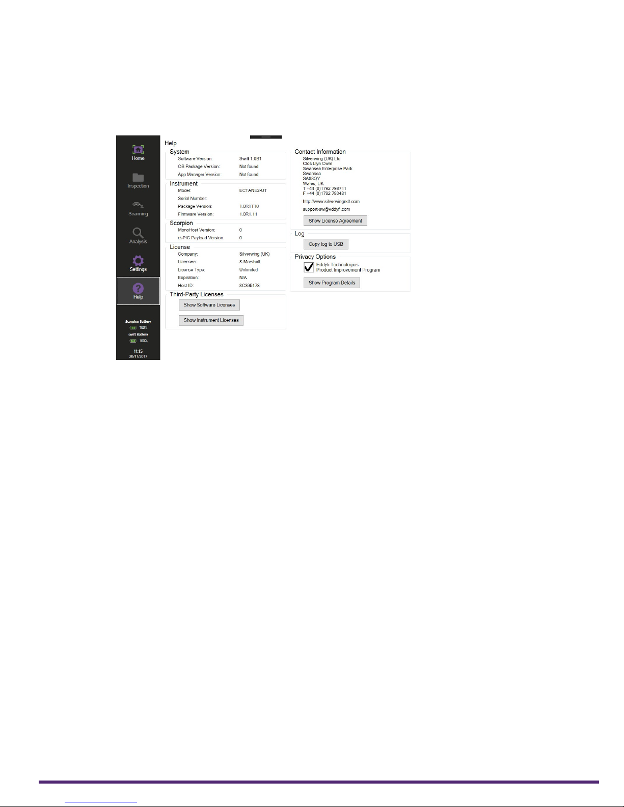
Help
Help contains information regarding Swift instrument, the software version and license
details. Here, it is possible to copy a log le to a USB device in case there is a problem with
the system.
Figure 3–17 Help
| 35
Page 48

Inspection Preparation
Chpter 4
Inspection
Preparation
36 | www.silverwingndt.com
Page 49
Inspection Preparation
Connecting Swift to Scorpion2
To connect the system together:
1. Remove Swift, Scorpion2 and umbilical cable from their transit cases.
2. Insert batteries into Swift and Scorpion2.
3. Apply silicone oil to the wheel probe and cleaning pad of Scorpion2.
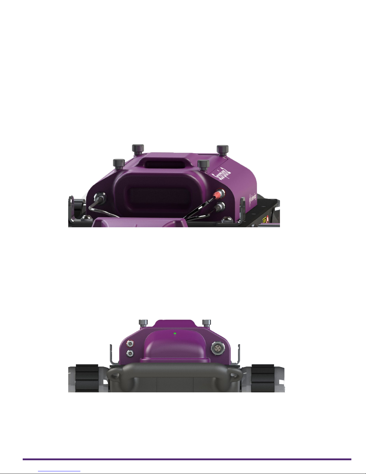
4. Check that both ultrasonic Lemo00 connectors from the wheel probe are securely
connected to the front of Scorpion2 crawler. Ensure the color of the connector boot
matches the color ring of the connector on the crawler.
5. Check that the Lemo0B connector for the probe head linear actuator is connected to
the front of Scorpion2 crawler. Ensure the red dot on the connector lines up with the
red dot on the bulkhead socket.
Figure 4–1 Scorpion2 front connectors
6. Unwind both sides of the umbilical cable to the required length, as failure to do so could
twist the cable.
7. Connect the umbilical Lemo2B connector to the rear of Scorpion2 crawler lid. Ensure
the red dot on the connector lines up with the red dot on the bulkhead socket.
8. Connect both umbilical ultrasonic Lemo00 connectors to the rear of Scorpion2 crawler
lid. Ensure the color of the connector boot matches the color ring of the connector on
the crawler.
9. Attach both umbilical tether clips to the anchor points on the rear handle.
Figure 4–2 Scorpion2 rear connectors
10. Connect the umbilical Lemo2B connector to the I/O connector on Swift. Ensure the red
dots are aligned.
11. Connect the ultrasonic Lemo00 connector with the red boot to the color coded TX
connector on Swift.
12. Connect the ultrasonic Lemo00 connector with the black boot to the color coded TX/
RX connector on Swift.
13. Attach a suitable tether line to Scorpion2 crawler anchor points.
| 37
Page 50

Inspection Preparation
14. Power on Swift. Ensure the emergency stop button is reset by rotating clockwise. Check
NOTE
It can take up to 30 seconds for Scorpion2 to boot. Once a connection is established, the
LED is lit Green and Swift software displays Scorpion2 battery status.
Inspection Surface Preparation
The condition of the inspection surface is critical to the quality of the results obtained from
the scanner.
The ferrous inspection surface to be inspected must:
• have a surface temperature of no greater than 80oC (176oF);
• have a maximum ambient temperature of no greater than 65
• have a minimum ambient temperature of no lower than -10
• have a minimum diameter of 3.0 m (10 ft) for external longitudinal inspection;
• have a minimum diameter of 3.0m (10 ft) for external circumferential inspection;
• have a minimum diameter of 5.0m (17 ft) for internal longitudinal inspection;
• have a minimum diameter of 3.0m (10 ft) for internal circumferential inspection;
• be free of excess rust, scale, ferrous debris, oil, ice, frost or any organic growth;
• have a minimum thickness of 5mm (13/64 in);
• have a maximum thickness of no greater than 100mm (4 in);
• be coated to a thickness no greater than 1mm (3/64 in).
the LED on Scorpion2 lid to establish the connection status. The LED displays the
following information:
• Green: Power on and communication with Swift
• Red Flashing: Power on but no communication with Swift
• O: No Power to Scorpion2
o
C (149oF);
o
C (14oF);
Inspecting on Slippery, Damp or Wet Surfaces
Slippery conditions will compromise the performance of the crawler. If the inspection
surface is slippery, then it is recommended to not drive the crawler or perform an inspection
at its maximum speed of travel.
Scan Path
Visually check the scan path of the crawler and identify if any obstructions exist. Driving
over obstructions could cause the crawler to slip or be dislodged from the inspection
surface.
Ensure there are no areas of non-ferrous material along the scan path. Driving across nonferrous material results in a loss of magnetic attraction that could cause the crawler to slip
or be dislodged from the inspection surface.
When operating Scorpion2 at height, cordon o an area of at least 6m, [20ft] in all
directions directly below the intended scan path.
38 | www.silverwingndt.com
Page 51
Inspection Preparation
Tether Line Attachment
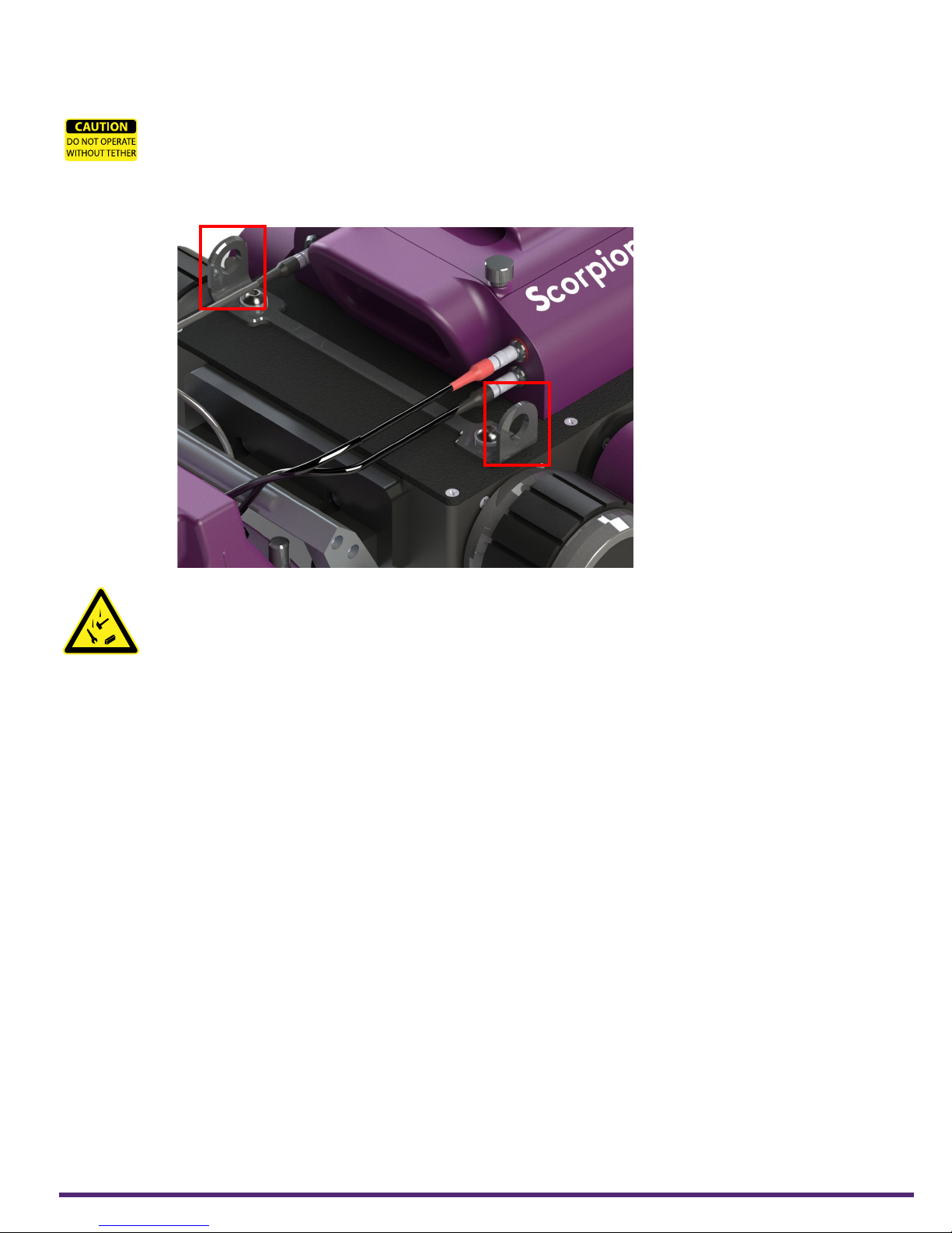
Two tether line attachment points are located on Scorpion2 crawler. During operation,
there must always be a tether line attached to Scorpion2 crawler with a proper tether
system to prevent the crawler from falling.
Figure 4–3 Tether points
DANGER FALLING OBJECT HAZARD!
Keep the area below an operating crawler clear at all times. A NO ENTRY ZONE must be
clearly marked and cordoned o directly below the crawler. The NO ENTRY ZONE must be
a minimum of 6m (20 ft) in all directions from the point below the crawler.
| 39
Page 52

Workow
Chpter 5
Workflow
40 | www.silverwingndt.com
Page 53
Typical Inspection Workow
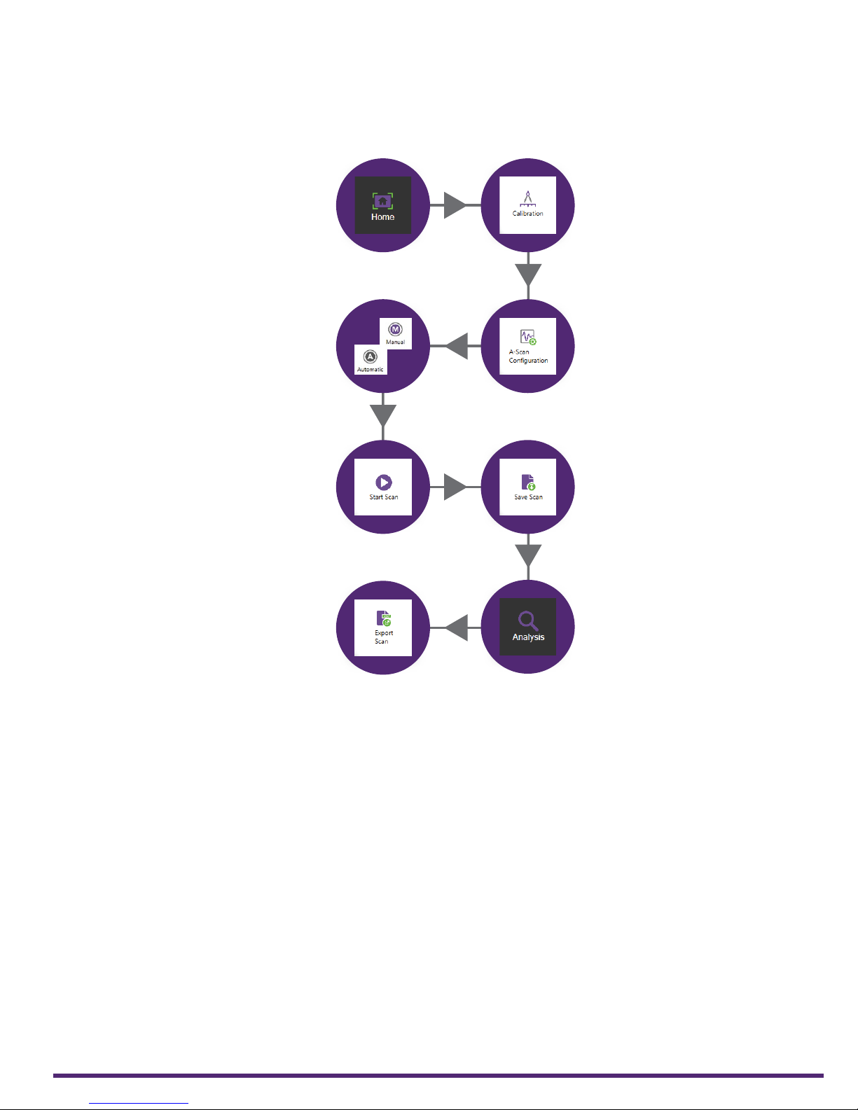
Figure 5–1 Typical inspection workow
Workow
New / Load Inspection
Determine the inspection
where the data is saved.
Acquisition Mode
Congure the acquisition mode of
the system using either an
Automatic or Manual scan mode.
Data Acquisition
Acquire data based on
the acquisition mode.
Calibration
Conduct or recall an
encoder calibration for
the acquisition device.
A-Scan Conguration
Congure or recall the
ultrasonic parameters and
gate setup for the scan.
Save Scan
Save the data in the
required format.
Export Inspection Data
Export the inspection
data for reporting
using CMAP.
Analysis
Conduct data analysis using
the software tools and
export scan images.
| 41
Page 54
Workow
New / Load Inspection
New Inspection:
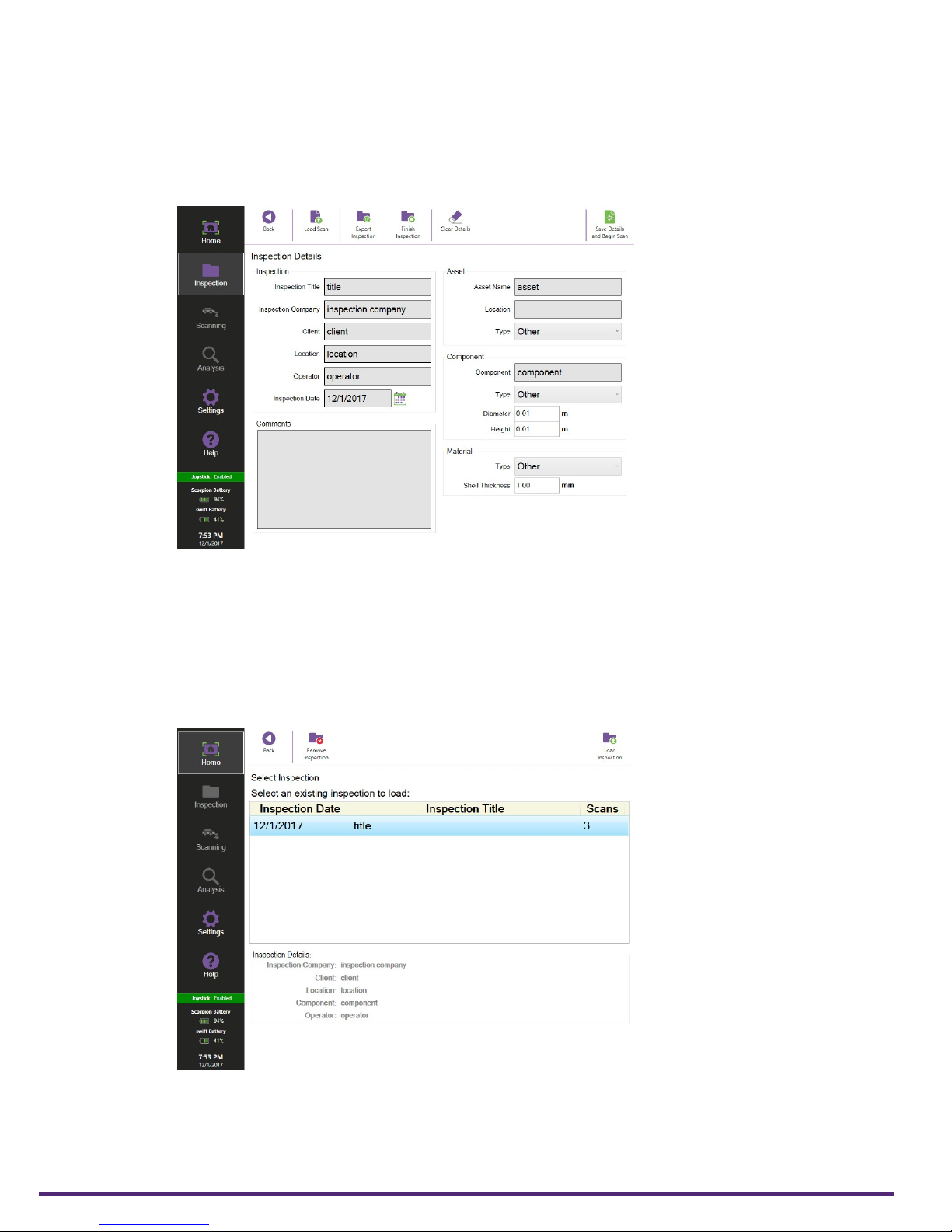
1. Tap New Inspection in the home window to load the Inspection Details window.
Figure 5–1 Inspection details window
2. Enter the required information for the inspection.
3. Tap Save Details and Begin Scan to continue.
Load Inspection
To load an existing inspection:
1. Tap Load Inspection in the Home window to load the Select Inspection window.
Figure 5–2 Select inspection window
2. Select the required inspection from the list of existing Inspections saved on Swift.
3. Tap Load Inspection.
4. In the Inspection Details window check the inspection details and edit if required.
5. Tap Save Details and Begin Scan to continue.
42 | www.silverwingndt.com
Page 55
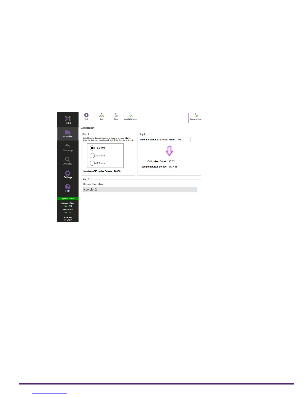
Acquisition Device Calibration
The correct encoder ratio must be used when inspecting with Scorpion2. Either perform a
new encoder calibration or load an encoder calibration if one already exists.
New Encoder Calibration
To perform a new encoder calibration:
1. Tap Calibration in the Acquisition Device window to load the Calibration window.
2. Place Scorpion2 crawler onto a ferrous surface, then mark a datum point on the
inspection surface.
Note: A marker line on the probe head cover shows the wheel probe position.
Figure 5–3 Calibration window
Workow
3. In Step 1, select a pre-dened distance for Scorpion2 to travel then tap Start.
Note: this drives the crawler forwards.
4. Tap Stop once the crawler has halted.
5. Measure the distance travelled by the scanner.
6. In Step 2, enter the distance travelled then tap the enter button. A calibration factor
and the pulses per revolution for the drive wheel are displayed.
Note: The calibration factor for Scorpion2 is typically around the value of 26 and the pulses
per rev is typically around the value of 1400.
7. In Step 3, enter a scanner description then tap Save and Finish. This saves the calibration
le and returns to the Acquisition Device window.
8. Tap Begin Acquisition to continue.
Load Encoder Calibration
To load an existing encoder calibration:
1. Tap Calibration in the Acquisition Device window to load the Calibration window.
2. Tap Load Calibration.
3. Select the required encoder calibration le name and tap Load.
4. Tap Save and Finish to return to the Acquisition Device window.
Note: If back is selected, the calibration is not loaded.
5. Tap Begin Acquisition to continue.
| 43
Page 56
Workow
A-Scan Conguration
Capturing accurate and reliable thickness gauge data requires:
1. Correct transducer selection. Scorpion2 scanner is tted with a 5MHz twin crystal
transducer.
2. An accurate reference block of the same material as that being tested. The calibration
or reference block should be made of material with the same sound velocity and
attenuation characteristics as the material to be inspected. It should have parallel
machined surfaces representing the thickness range to be inspected. A minimum of two
thicknesses representing the minimum and maximum values is acceptable for calibration,
however it is recommended that the calibration block has four dierent thickness
sections to cover the expected thickness range to allow for verication of the calibration.
3. Correct ultrasonic calibration on Swift. The aim of the calibration is to set the ultrasonic
parameters to clearly view the echoes and position the gates to read the correct
material thickness.
A-Scan Calibration
It is possible to calibrate using only one known material thickness. However it is recommended
to verify the calibration across a range of known thicknesses.
To conduct a manual A-Scan calibration:
1. Place the transducer onto the calibration block.
2. Tap A-Scan Conguration to access the A-Scan Conguration window.
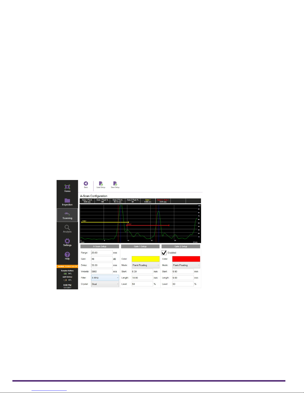
Figure 5–4 A-Scan conguration
3. Set Crystal so that it matches the transducer connected to Swift.
4. Set Filter so that it matches the transducer connected to Swift.
5. Set Velocit y to the material velocity under test.
Note: The velocity for mild steel is 5960 m/s [0.234 in/us].
6. Adjust Range and Delay so the echoes from the desired thickness range can be viewed.
It is recommended to view no more than three back wall echoes and that the rst back
wall echo is positioned along the time base value that corresponds to the material
thickness.
Note: Due to the thickness of the wheel probe tires, delay is typically around 35mm (1.3 in)
7. Adjust the gain so that the second echo is at about 80% full screen height.
8. Set the Mode of Gate 1 to the desired gate trigger. It is recommended to set to Flank
Floating.
44 | www.silverwingndt.com
Page 57
9. Position Gate 1 across the rst back wall echo so that is covers the thickness range of
interest. Adjust the level of the gates to around 40% of echo height.
10. Tick Enabled in Gate2 setup.
11. Set the Mode of Gate 2 to the same as Gate 1.
12. Position Gate 2 across the second back wall echo so that it covers the thickness range
of interest. Adjust the level of the gates to around 40% of echo height.
Note: If Gate2-Gate1 thickness value does not match the true thickness of the calibration
block used then adjust Velocity until the true thickness is displayed.
13. Adjust Delay so that the thickness value of Gate 1 is identical to Gate 2 thickness value.
Save Setup
To save the A-Scan setting le:
1. Tap Save Setup in the A-Scan Conguration window.
2. Enter a suitable le name then tap Save.
3. Tap Back to return to the Acquisition: B-Scan window.
Load Setup
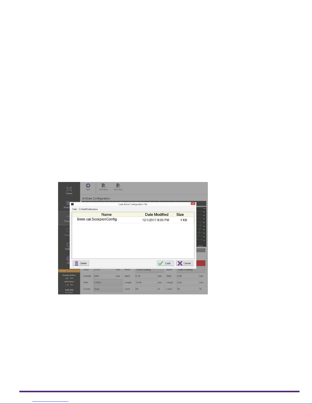
To load a pre-saved A-Scan setting le:
1. Tap Load Setup in the A-Scan Conguration window.
Figure 5–5 Load A-Scan conguration window
Workow
2. Select the required setup le then tap Load.
3. Tap Back to return to the Acquisition: B-Scan window.
| 45
Page 58
Workow
Acquisition Mode
A suitable acquisition mode must be selected in order for Scorpion2 to perform a scan. The
available modes are:
• Automatic mode
Scorpion2 drives automatically and relies on both encoders to actively steer during the
scan to ensure it travels in a straight line.
Note: Surface condition and scan direction can aect steering accuracy.
When conducting an automatic scan, details of a scan oset, scan length, scan
direction and scan speed must be entered prior to a scan.
• Manual mode
Scorpion2 is driven by either using Swift joystick or by holding the nudge forward and
backward button on Swift, and relies on the right hand encoder to record the distance
travelled. When conducting a manual scan, details of a scan oset must be entered
prior to a scan.
The maximum distance the crawler can travel in one scan is 50m (164 ft).
If the battery level of Scorpion2 is 15% or below the crawler is prevented from performing
an inspection. When attempting to inspect, a warning message is displayed. Scorpion2 can
still be driven using the joystick, but in order to continue the inspection, the battery in
Scorpion2 must be changed.
CAUTION!
If the battery level of Scorpion2 is 15% or below, the system prevents any scanning. To
continue, change the battery in Scorpion2.
46 | www.silverwingndt.com
Page 59
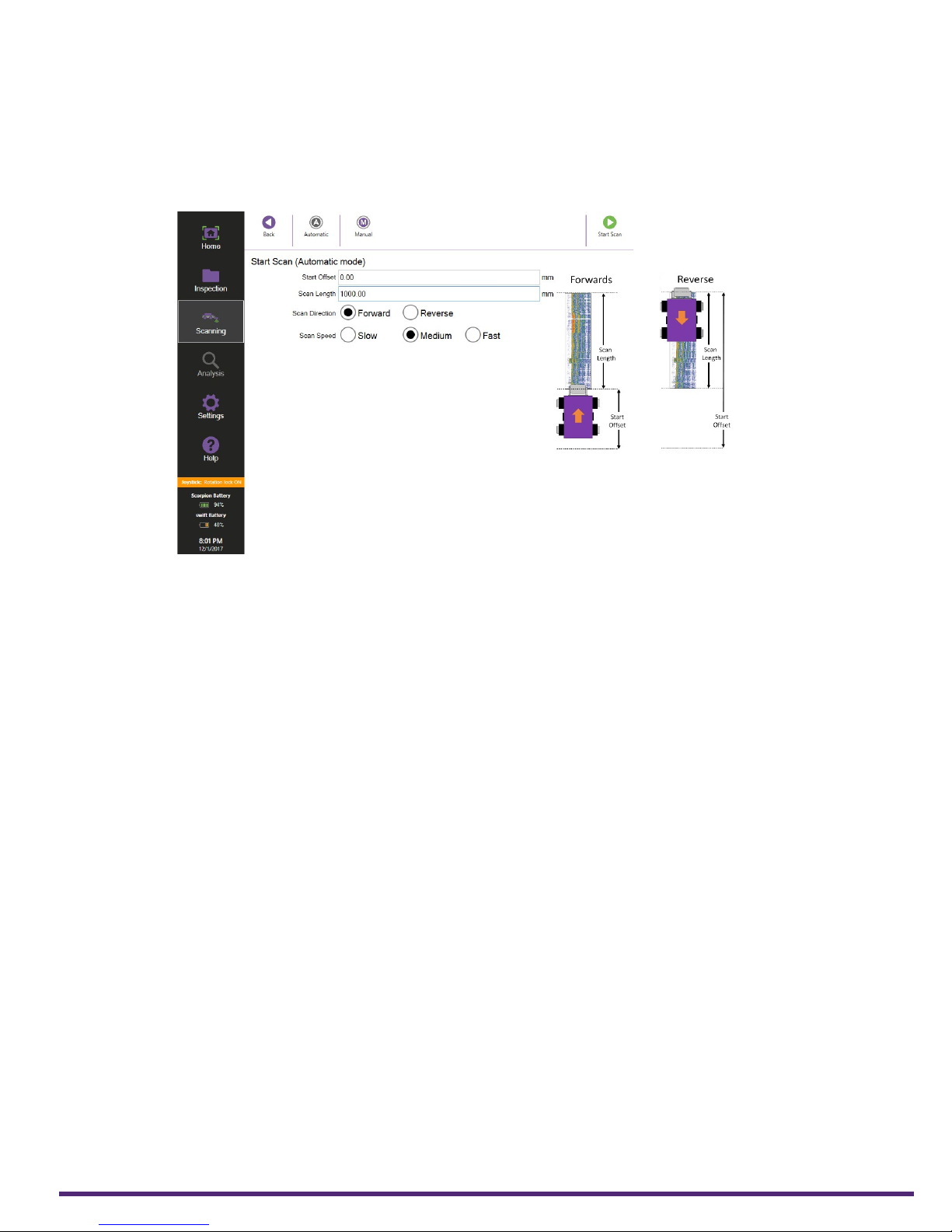
Automatic Mode
To begin an automatic scan:
1. Tap Start Scan in the Acquisition: B-Scan window.
2. Tap Automatic to view the Start Scan (Automatic mode) window.
Figure 5–6 Start scan automatic window
Workow
3. Select the desired Scan Direction. Either Forward or Reverse.
4. Enter a Start Oset using the keypad. The start oset is a measurement from an
inspection reference location to the actual position of the wheel probe.
5. Enter a Scan Length using the keypad.
6. Select a Scan Speed.
7. Click Start Scan to begin the acquisition.
During the acquisition Scorpion2 automatically drives the desired scan length then
stops.
Tap Pause to stop the automatic drive of Scorpion2. A paused message appears on the
scan. When paused, Scorpion2 can be manually driven using the joystick or by holding
the nudge forward and backward button on Swift.
The speed of the crawler can be altered by selecting the relevant speed option.
To alter the ultrasonic setup or gate parameters during a scan tap A-Scan Conguration.
Tap Resume Scan to continue the automatic drive of Scorpion2.
If the Stop Movement button on Swift is pressed, the crawler halts. To resume tap
Pause Scan then tap Resume Scan.
8. Tap Stop Scan when the data acquisition is complete and progress onto the Analysis
window.
9. Tap Save Scan in the Analysis Window.
10. In the Save Scan window select the desired mode for saving the data.
11. To progress to the next scan tap Save->Next Scan. Position the crawler as required and
repeat steps 1 through 10.
| 47
Page 60
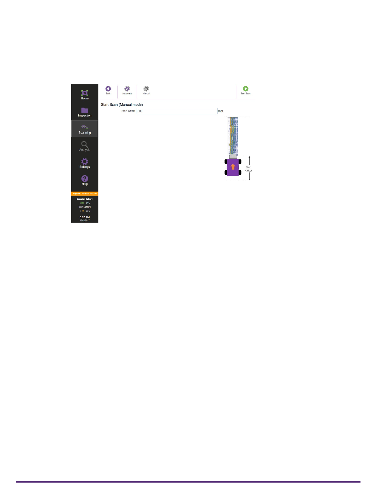
Workow
Manual Mode
To begin a manual scan:
1. Tap Start Scan in the Acquisition: B-Scan window.
2. Tap Manual to view the Start Scan (Manual mode) window.
Figure 5–7 Start Scan (manual mode) window
3. Enter a Start Oset using the keypad. The start oset is a measurement from an
inspection reference location to the actual position of the wheel probe.
4. Click Start Scan to begin the acquisition.
Drive Scorpion2 manually by either using Swift joystick or by holding the nudge forward
and backward button on Swift.
To alter the ultrasonic setup or gate parameters during a scan, tap A-Scan
Conguration.
5. Tap Stop Scan when the data acquisition is complete and progress onto the Analysis
B-Scan Window.
6. Tap Save Scan in the Analysis B-Scan Window.
7. In the Save Scan window select the desired mode of saving the data as either Adjacent
Scans, Gridding or Tank shell.
8. To progress to the next scan tap Save->Next Scan. Position the crawler as required and
repeat steps 1 through 7.
48 | www.silverwingndt.com
Page 61
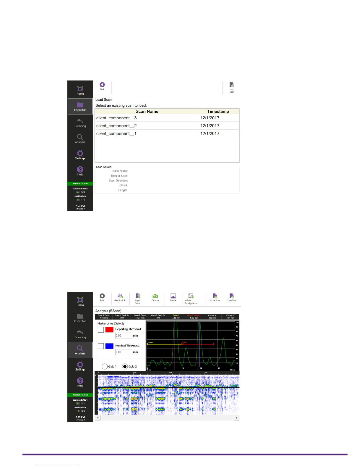
Analysis
Loading a Saved Scan
To load a scan for analysis:
Figure 5–8 Load scan window
Workow
1. Tap Inspection on the sidebar.
2. Tap Load Scan.
3. Select the required scan from the list then tap Load Scan.
B-Scan Viewing Options
The view of the B-Scan is set to zoom to t the scan into the window. Use the zoom buttons
on Swift to adjust the view and scroll use the scroll bar below the B-Scan.
Tap on the B-Scan view to display the corresponding A-Scan signal at the cross hair location.
Use the directional arrows on Swift to allow for on screen cursor adjustment.
The B-Scan data can be displayed as either an Amplitude or Prole view.
| 49
Page 62
Workow
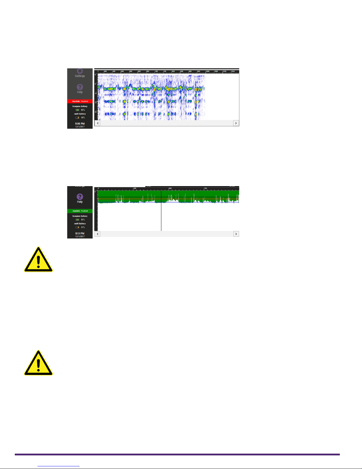
Amplitude View
This displays a multi-colored B-Scan view based on the amplitude of the A-Scan signal. The
color palette for the amplitude view can be changed in the Settings sidebar menu.
Figure 5–9 Amplitude view
Prole View
This displays the B-Scan view as a cross section based on material thickness values identied
by the selected gate.
Figure 5–10 Prole view
CAUTION!
If no back wall echoe crosses the selected gate, or if there is a loss of back wall echo due
to surface irregularities or the presence of corrosion, then the prole views show 0 thickness
because no values are recorded by the gate.
A-Scan Gate Adjustment
Gate positions can be altered after the scan if required. Any changes made will alter the
thickness values recorded and the B-Scan prole view.
To access the gate setup menu:
1. Tap A-Scan Congurations.
2. Adjust the gate properties as required.
CAUTION!
Any adjustment to the measurement gate position after a scan alters the thickness value
and prole views.
50 | www.silverwingndt.com
Page 63
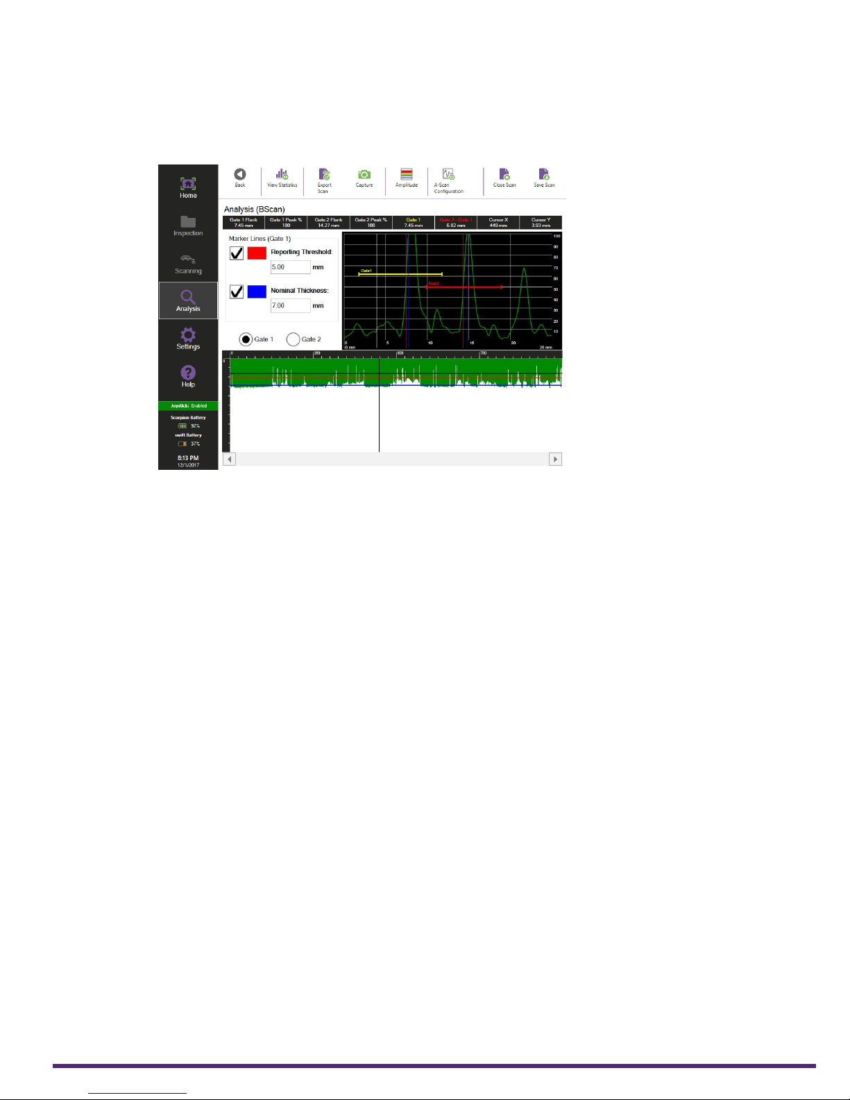
View Marker Lines
A horizontal line can be displayed on the B-Scan to indicate a reporting threshold and a
nominal thickness. To display:
Figure 5–11 B-Scan analysis marker lines
Workow
1. Tap View Marker Lines.
2. Select the required Gate option and Tap Prole v i e w.
3. Tick the required line option then enter the thickness value into the text box using the
keypad. Tap the color box to change the line color.
View Statistics
Statistical information relating to the mean, maximum and minimum thickness of the
selected gate can be shown along with their location on the scan. To display this information:
1. Tap View Statistics.
2. Select the required Gate option.
3. Tick to display the location of the minimum and maximum thicknesses found on the
scan. Tap the color box to change the line color.
| 51
Page 64
Workow
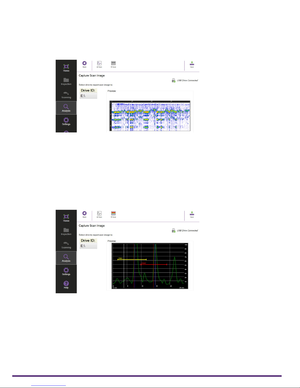
Export B-Scan Images to USB
Images of the B-Scan can be exported from Swift software onto a USB device.
To export the B-Scan image displayed in the B-Scan window:
Figure 5–12 Capture B-Scan image
1. Adjust the B-Scan view to suit.
2. Tap Capture.
3. Insert a USB device, ensure USB Drive connected is displayed.
4. Tap B-Scan.
5. Tap Save.
6. Enter a le name and tap Save.
Export A-Scan Images to USB
To export the A-Scan image
Figure 5–13 Capture A-Scan image
1. Position the cross hair on the B-Scan to obtain the required A-Scan.
2. Tap Capture.
3. Insert a USB device, ensure USB Drive connected is displayed.
4. Tap A-Scan.
5. Tap Save.
6. Enter a le name and tap Save.
52 | www.silverwingndt.com
Page 65
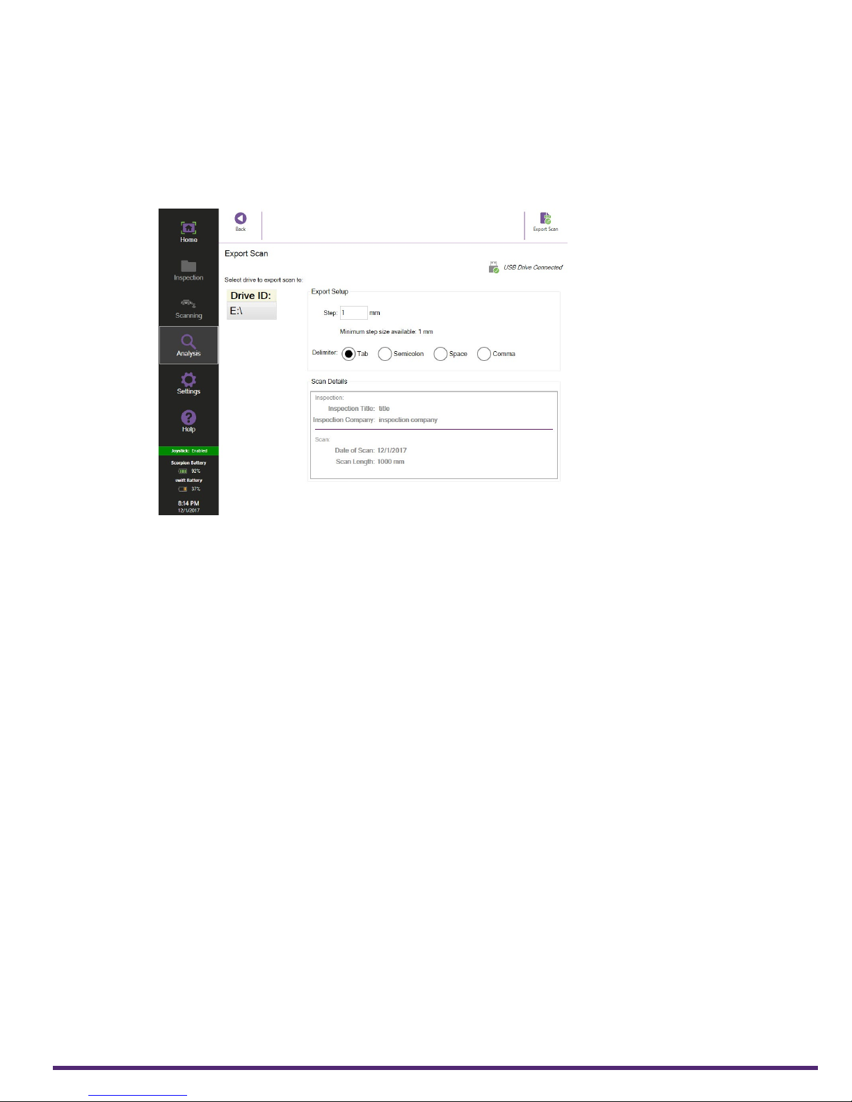
Export a Scan to CSV
The thickness measurement data of a scan can be exported as a CSV le. During the
exporting process, the step and delimiter symbol must be selected.
To export the scan thickness data to CSV:
1. Tap Export Scan.
Figure 5–14 Export scan window
Workow
2. Set the export step.
3. Select the delimiter symbol.
4. Tap Export Scan.
5. Tap Save.
Loading a CSV le in Microsoft Excel
When loading a CSV le in to Microsoft Excel, use the Text Import Wizard tool and select
the same delimiter symbol used to export the data.
| 53
Page 66

Workow
Exporting Inspection Data
The inspection data on Swift can be exported to an external USB drive. No data is removed
from Swift when using the export function, so any old inspection data must also be removed
from Swift.
To export the data from Swift unit:
1. Tap Inspection on the sidebar to load the Inspection Details window.
2. Tap Export Inspection.
3. Insert the external USB drive into the USB port.
4. Tap Export Inspection.
5. Enter a le name then tap Save.
The exported le is saved in a .CMX format which can only be viewed using the CMAP
reporting software.
Finish Inspection
Once the scanning and data analysis of an inspection is complete, the inspection can be
closed.
1. Tap Inspection on the sidebar.
2. Tap Finish Inspection.
Deleting an Inspection from Swift
1. Tap Home.
2. Tap Load Inspection.
3. Select the required inspection for removal and tap Remove Inspection.
4. Follow the onscreen instructions to complete this operation.
Deleting All Swift User Data
To delete all the user data on Swift:
1. Connect a USB keyboard to one of the Swift’s USB ports.
2. Tap Help on the sidebar.
3. Tap or click inside the Help section.
4. On the keyboard press ALT+ F2. A conrmation dialog box appears.
5. Follow the onscreen instructions to complete this operation.
All the user data is removed from the instrument.
54 | www.silverwingndt.com
Page 67

Troubleshooting and Maintenance
Chapter 6
Troubleshooting and
Maintenance
55 | www.silverwingndt.com
Page 68
Troubleshooting and Maintenance
Maintaining Swift
Because of its design, Swift instrument only requires minimal maintenance. Since Swift has
no moving parts, it also does not require any preventive maintenance. We recommend a
regular inspection of the instrument to ensure that it is properly grounded. We also strongly
recommend that an annual calibration and a factory-performed preventive maintenance
is conducted by an ocially qualied Eddy technician.
Cleaning Swift
It is recommended that the instrument is cleaned after every inspection.
1. Make sure that the instrument is o and that the AC power adaptor is disconnected.
2. To bring the instrument back to its original nish, clean it with a soft cloth.
WARNING!
Do not spray the instrument with chemical cleansers or water. Doing so may lead to short
circuits and damage to the instrument.
Important
To remove stubborn stains, use a cloth moistened with soft, soapy solution. Do not use
abrasives or strong solvents as they could damage the nish. Wait until the instrument is
completely dry before connecting the power cord or cables.
Updating and Upgrading Software
Before performing any maintenance on the software, rst meet the following requirements:
• USB mass storage device with a minimum of 4 GB free space
• Hardwired Internet connection
There are two methods of updating or upgrading the software.
Standard Method
1. Connect Swift to a power outlet with the power cable.
2. Turn on Swift and wait for the software to start.
3. Download the *.SwiftUpdate le from the Silverwing Web site.
Save the le in an easy-to-remember location on your computer.
4. Copy the *.SwiftUpdate to the root of a USB mass storage device.
5. Once copied, remove the mass storage device and connect it to one of Swift’s two USB
ports
A dialog box appears prompting you to proceed.
Important
Do not connect your mass storage device to the QUICK COPY USB port.
6. Tap Yes.
7. In the list that appears, tap the desired update le, and then tap Update.
Important
If performing a complete Swift OS update, perform steps 8 to 10. In the case of a software
update, the instrument restarts automatically.
8. To select Yes, press the keypad’s up arrow. Press any other button to select No.
You are prompted to conrm again.
| 56
Page 69
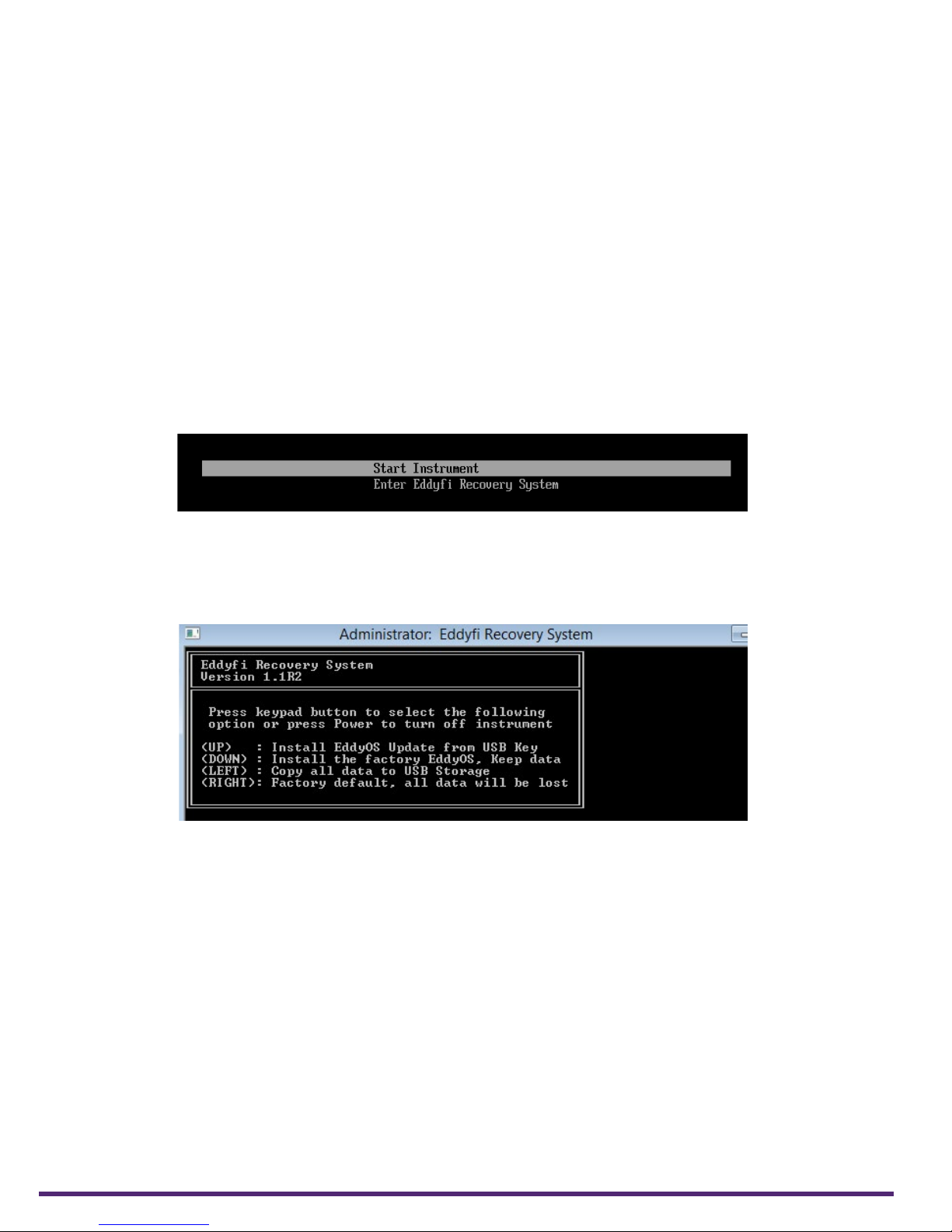
Troubleshooting and Maintenance
9. Press the keypad’s up arrow again.
The update process starts. This normally takes between 5 and 10 minute, depending
on the speed of your mass storage device. When the process is complete, the system
restarts.
10. Activate Windows.
See Activating Windows on page 57 for details.
System Recovery Method
1. Connect Swift to a power outlet with the power cable.
2. Make sure that Swift is o.
If it is not, turn it o.
3. Turn on the instrument.
4. Immediately and simultaneously press the nudge forward button and the zoom out
button until the following appears.
Figure 6–1 Options menu
5. With the keypad arrows, select Enter Eddy System Recovery, and then press the Enter
button.
You are prompted to wait until the following appears.
Figure 6–2 System recovery interface
6. Using the keypad arrows, select Install the factory EddyOS update, keep data.
7. When prompted, press the up arrow of the keypad.
The update process starts. This normally takes between 5 and 10 minute. When the
process is complete, the system restarts.
8. Activate Windows.
Activating Windows
Microsoft requires that you activate Windows to be able to use it. The activation process is
automatic when you connect Swift to the Internet through an Ethernet cable. To proceed :
1. Make sure that Swift is on and that the software is running.
2. Connect an Ethernet cable to Swift.
3. Connect the other end of your Ethernet cable to a network (local area network or other
access point).
Wait until a dialog box conrming the activation of Windows appears on screen. If you do
not activate Windows, every time you start Swift, a message will remind you to do so. You
have 30 days to activate Windows before it locks up.
57 | www.silverwingndt.com
Page 70
Troubleshooting and Maintenance
Known Issue With System Updates/Upgrades
On some units, a blue Windows error screen may appear when you attempt to enter the
system recovery, which can cause the unit to start normally. Try performing the update
procedure again.
Troubleshooting
Troubleshooting System Updates/Upgrades
• No update le found. This appears in the update list or in the system recovery. Make
sure that you only have one USB mass storage device connected to Swift. Also make
sure that the le is in the root folder of the device.
• Cannot display the options screen. You do not press and hold the nudge forward
button and the change layout button long enough, you do not press and hold the
correct buttons, or you do not press and hold the buttons quickly enough after turning
on Swift. Try holding the power button for two seconds, and then quickly pressing and
holding the nudge forward button and the zoom out button.
• Using the system recovery method. Swift restarted normally or a blue error screen
appeared on the screen. Perform the procedure again.
• Unable to activate Windows. Make sure that your Ethernet cable is sound. Make sure
that you have Internet access. Make sure you are using DHCP. Turn on Swift after
connecting the Ethernet cable and network. If you do not see a message warning you
that Windows is not activated when it starts, Windows is activated.
Scorpion2 Crawler Maintenance
Scorpion2 crawler is designed for minimal maintenance. After each inspection, it is
recommended that, due to its moving parts, some preventative maintenance and cleaning
around critical components is required. We also strongly recommend that an annual
calibration and factory-performed preventive maintenance is conducted by an ocially
qualied Silverwing technician.
WARNING!
Do not attempt to unscrew and remove the lid of Scorpion2 crawler. This can compromise
the integrity of the seal and cause damage to internal components. Damage to the seal or
removal of the lid will void the manufacturer warranty.
Drive Wheels
Clean any build-up of debris in the treads of the four drive wheels. Also clean any build-up
between the wheels and the crawler chassis. During use on wet or dusty surfaces, the
wheels may spin and become polished. If they do become polished, lightly roughen the
surface with 120 grit emery cloth.
Encoders
Clean any build-up of dirt around each encoder wheel. Check there is sucient spring
pressure to keep the encoder wheels in contact with the surface at all times. Ensure the
encoders do not get damaged during use, as it could cause issues with the automatic drive
and steering of the crawler as well as distance measurement inaccuracies.
Cabling
Check all cabling for any damage that could have been caused during use. Do not walk,
stand, trap or place objects on top of the umbilical cable. If a cable is damaged, do not use
until it is repaired.
| 58
Page 71
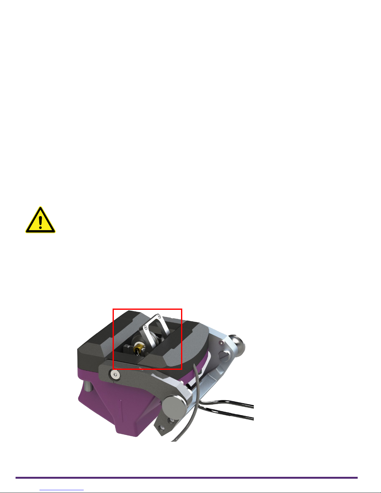
Troubleshooting and Maintenance
Dry Coupled Wheel Probe
Remove the wheel probe for further maintenance and replace the cleaning pad when there
is a build-up of debris.
Wear Runners
Clean any build-up of dirt around the wear runners. Check the surface for any damage or
deep scoring. Replace when the edge wear marks have worn at.
Dry Coupled Wheel Probe Maintenance
The dry coupled rubber of the wheel probe is most eective when the contact surface is
slightly tacky. As the Wheel Probe picks up dust and debris from the surface, it becomes
less eective. A cleaning pad removes any dust and debris from the wheel probe and
applies a thin lm of oil to help improve coupling. Silicone oil, such as silicone brake uid,
should be manually applied to the cleaning pad to ensure that it remains moist.
Discoloration of the wheel probe tire suggests they need to be cleaned using a cloth
moistened with acetone. This helps to restore the tire to their original ‘tacky’ condition.
The frequency of cleaning depends upon the condition in which the unit is being used, for
example where the paint surface is particularly dusty (or coated with a thick ‘bloom’), it
may be necessary to clean the tires after each scan.
WARNING!
Only use silicone oil to moisten the cleaning pad. Any other form of mineral oil will damage
the wheel probe tires.
The use of any “oil” other than specied by the manufacturer will invalidate the warranty
on the wheel probe tires.
Wheel Probe Removal
To remove the wheel probe from the probe holder:
1. Disconnect the two Lemo00 connectors at the front of the crawler.
2. Unscrew the two screws of the probe housing lid and lift open.
Figure 6–3 Wheel probe removal
3. Remove the wheel probe from the probe housing. Ensure the wheel probe cables and
Lemo00 connectors feed through the probe holder cover.
59 | www.silverwingndt.com
Page 72

Troubleshooting and Maintenance
Cleaning Pad Replacement
The cleaning pad is located within the inner probe sleeve, above the wheel probe. To replace,
1. Remove the wheel probe.
2. Remove the old cleaning pad from the probe housing.
3. Slide in a new cleaning pad.
4. Replace the wheel probe.
Wheel Probe Replacement
To replace the wheel probe into the probe holder:
1. Pass the wheel probe cables and Lemo00 connectors through the guides in the probe
holder cover.
2. Ret the wheel probe into the probe housing. Ensure the markings on the axle face
downwards towards the inspection surface.
3. Close the probe housing lid and secure the two screws.
4. Connect the Lemo00 connectors back to the front of Scorpion2.
Wheel Probe Servicing
The wheel probe can be stripped for cleaning and involves removing the tires and the cork
washer.
Wheel Probe Strip Down
1. Using the circlip pliers, remove both circlips on either side of the wheel probe axle.
2. Remove the side plates then carefully slide each of the wheel probe tires away from
the transducer, over the axles and onto the cables.
Inspection and Cleaning
Inspect the tires for any signs of splitting, cracking, excessive abrasion or any evidence of
swelling due to contact with mineral oil. Check the condition of the cork insulating washer
and ensure that it sits snugly and turns freely in the groove. Check that the ball bearings
in the side plates turn freely.
Use acetone to clean all components and surfaces. Take extra care that all traces of lm
and dirt are removed, especially around the outer circumference and perspex plug over the
crystal and the inner face of the wheel probe tires.
Tire Replacement
If new tires are to be tted, it is very important they are rst cleaned with acetone to
remove the protective lm.
Wheel Probe Re-Assembly
1. Using the syringe, draw up a small amount of silicone oil from the source bottle and
apply a small amount of silicone oil to the inner face of the wheel probe tires.
2. Inspect the cork washer for correct t / damage.
3. Re-t the tires, side plates and circlips. Check for a positive ‘click’ when securing the
circlip, to ensure it is seated correctly in the groove.
| 60
Page 73

Using the Optional Harness
Appendix A
Using the Optional
Harness
61 | www.silverwingndt.com
Page 74
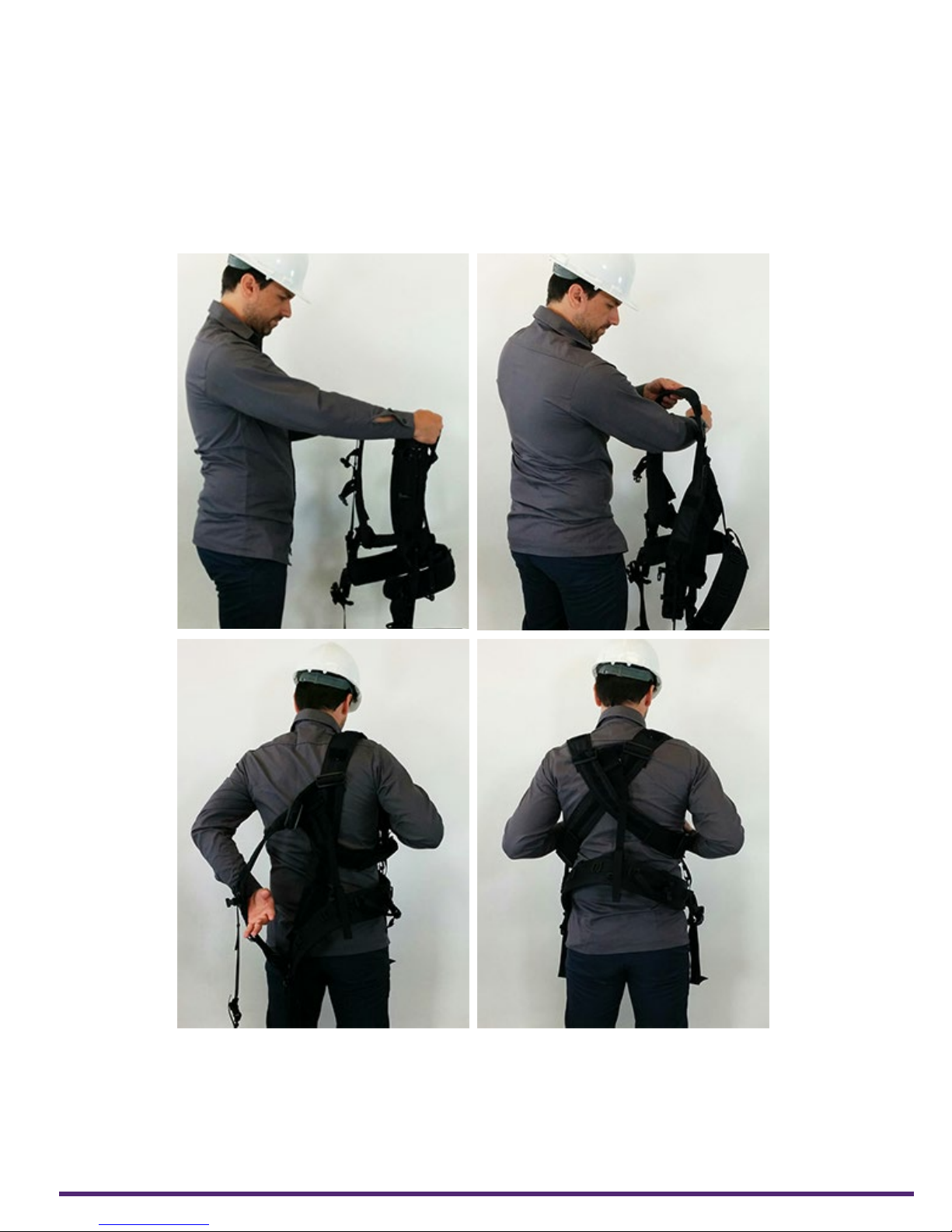
Using the Optional Harness
Adjusting the Harness
Harnessing Swift requires a number of specic adjustments so that you feel comfortable
wearing the harness.
Adjusting the Harness to your Body
1. Grab the harness shoulder straps and slip it over your shoulders as you would a jacket.
Figure A–1 Slipping the harness on
2. Verify the t of the harness.
Visualize working with Swift before making any adjustments to the shoulder straps and
height of the belt.
3. Slip out of the harness.
4. Use the underarm straps and shoulder blade rings to adjust the t of your shoulder
straps. You may need to perform this adjustment several times to get the proper t.
| 62
Page 75
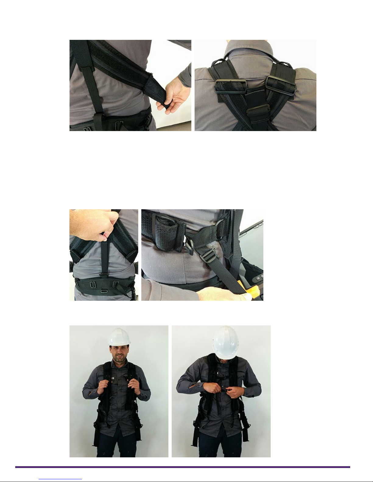
Using the Optional Harness
Figure A–2 Adjusting the shoulder straps
5. Use the back and side belt straps to adjust the height of the harness’ belt to suit your
body type.
You may need to perform this adjustment several times to get the proper t.
Note
Your belt’s height determines the lowest position of Swift. Adjust this height so that the
display of the instrument is easy to see—for that, the belt could end up higher than your
hips.
Figure A–3 Adjusting the belt’s height
6. Once your belt and shoulder straps are adjusted, clip and tighten the chest straps.
Figure A–4 Securing the chest straps
63 | www.silverwingndt.com
Page 76
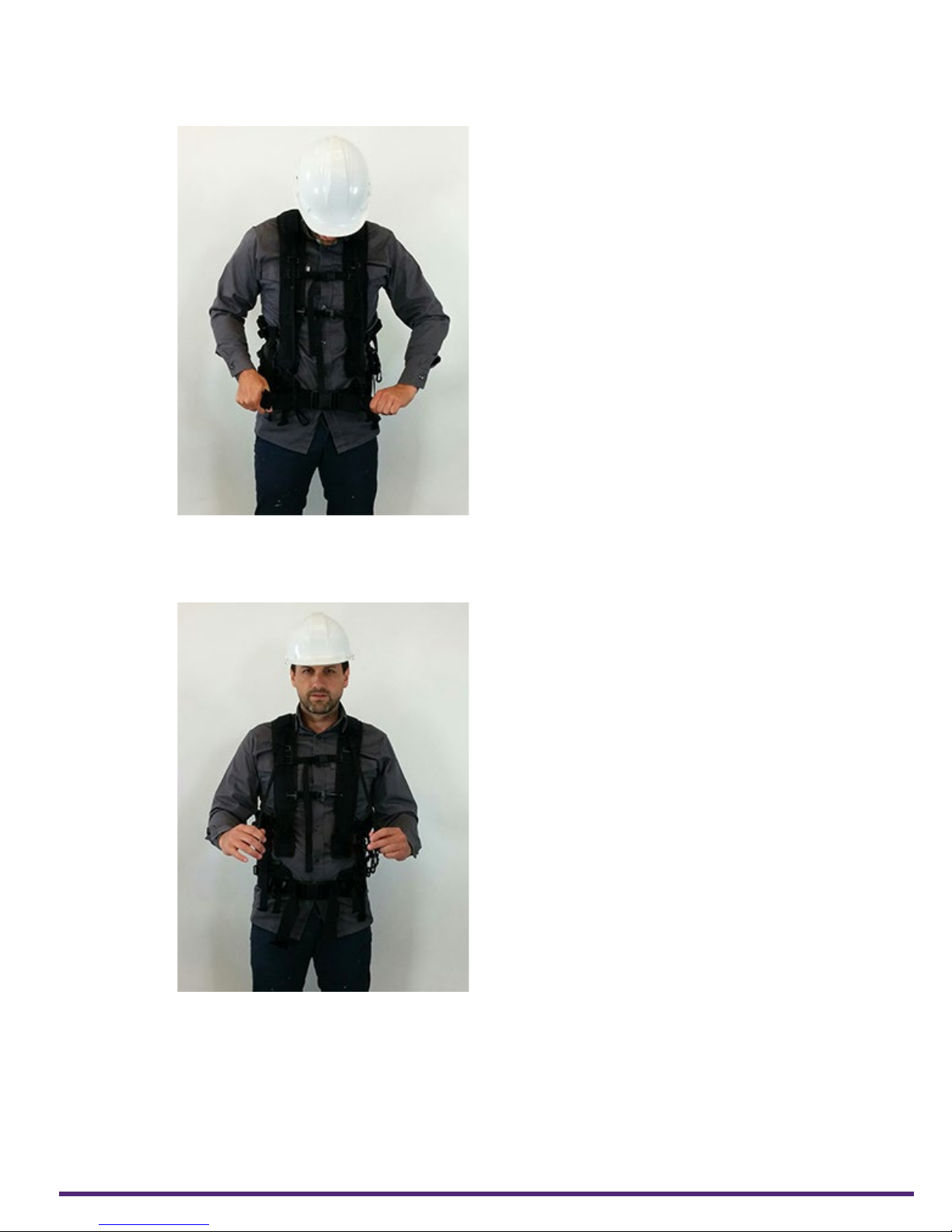
Using the Optional Harness
7. Secure the belt around your waist, according to the height you have adjusted it.
Figure A–5 Securing the belt
8. Make sure that the harness ts snuggly.
9. Make sure that the harness’ shoulder anchor straps are loose.
Figure A–6 Shoulder anchor straps
10. Unfasten the two straps at each end of the shoulder anchor straps.
Place them within hands reach. You will need them.
| 64
Page 77
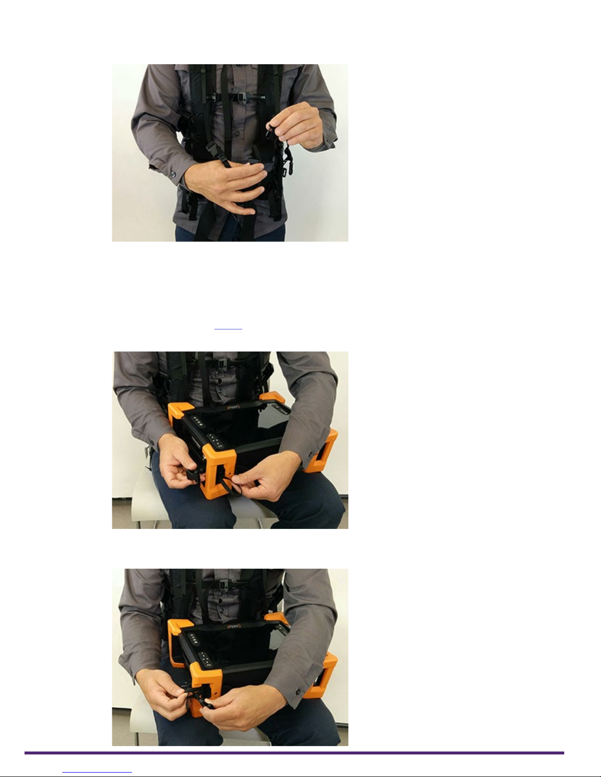
Using the Optional Harness
Figure A–7 Unfastening the straps
11. Sit down.
12. Place Swift horizontally in your lap.
13. Slip the looped portion of the strap removed above in the hook of one of the two upper
Swift bumpers, as illustrated.
Note
Illustrated here is Reddy. Manipulations on Swift are the same.
Figure A–8 Sliding strap loop through bumper hook
14. Slip the clip through the strap hoop, and then pull to tighten into place, as illustrated.
Figure A–9 Securing anchor strap
65 | www.silverwingndt.com
Page 78
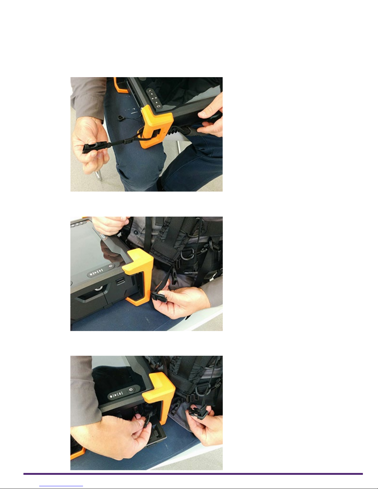
Using the Optional Harness
15. Repeat the previous two steps for the opposite upper bumper.
Note
You can also secure the straps to the bumpers in a more elegant and less easy-to-remove
fashion, as illustrated here.
Figure A–10 Alternative method of securing anchor strap to bumper
16. Locate the anchor strap on the harness’ belt.
Figure A–11 Anchor strap on harness belt
17. Open the battery compartment door and slip the male buckle of the anchor strap.
Figure A–12 Slipping male buckle through bumper
| 66
Page 79
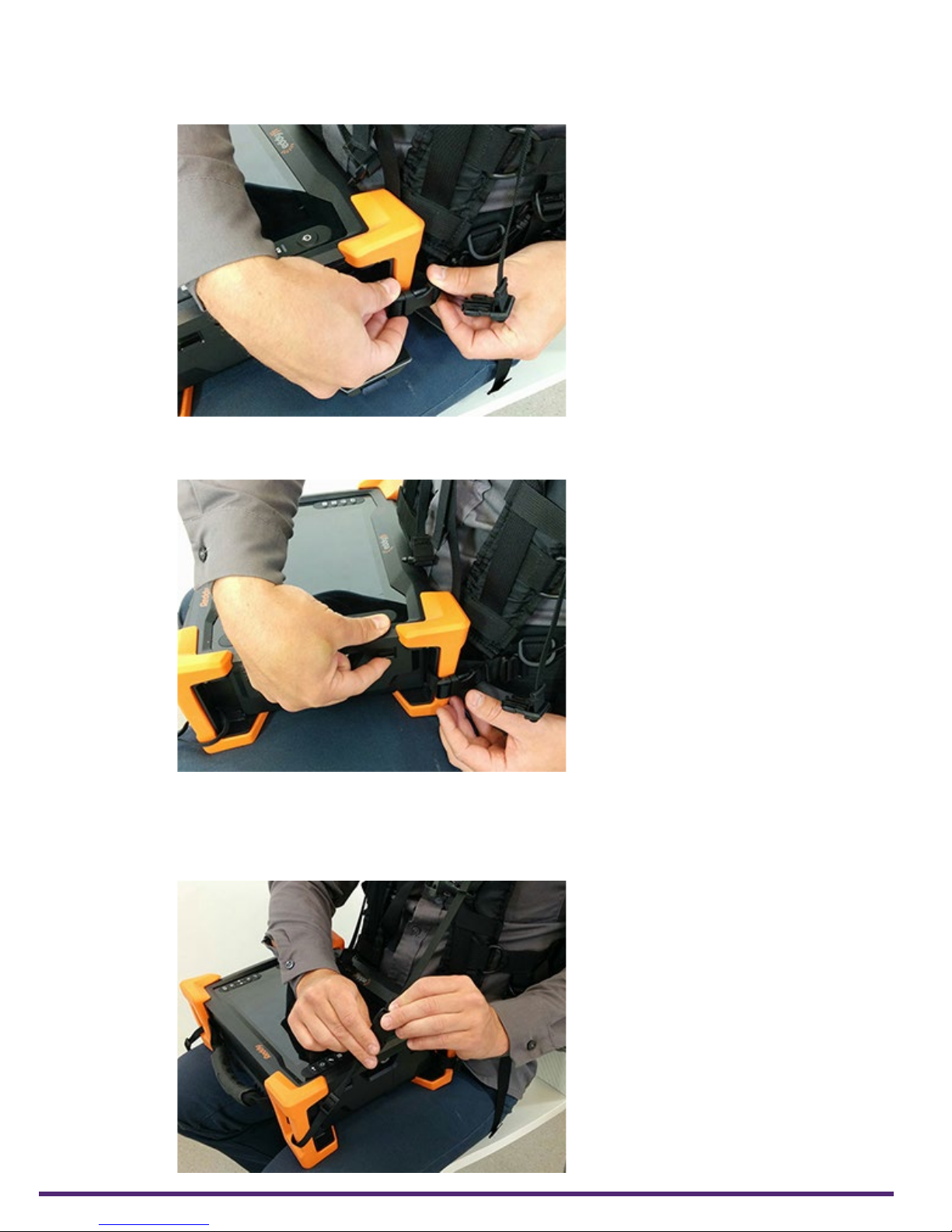
Using the Optional Harness
18. Mate the male buckle to its female counterpart.
Figure A–13 Mating battery compartment side anchor strap
19. Close and secure the battery compartment door.
Figure A–14 Closing battery compartment door.
20. Repeat the procedure for the opposite belt anchor strap (no door to open).
21. Adjust the length of the anchor straps until comfortable.
22. Mate the left male buckle of the shoulder anchor strap to its female counterpart.
Figure A–15 Mating shoulder anchor strap
67 | www.silverwingndt.com
Page 80
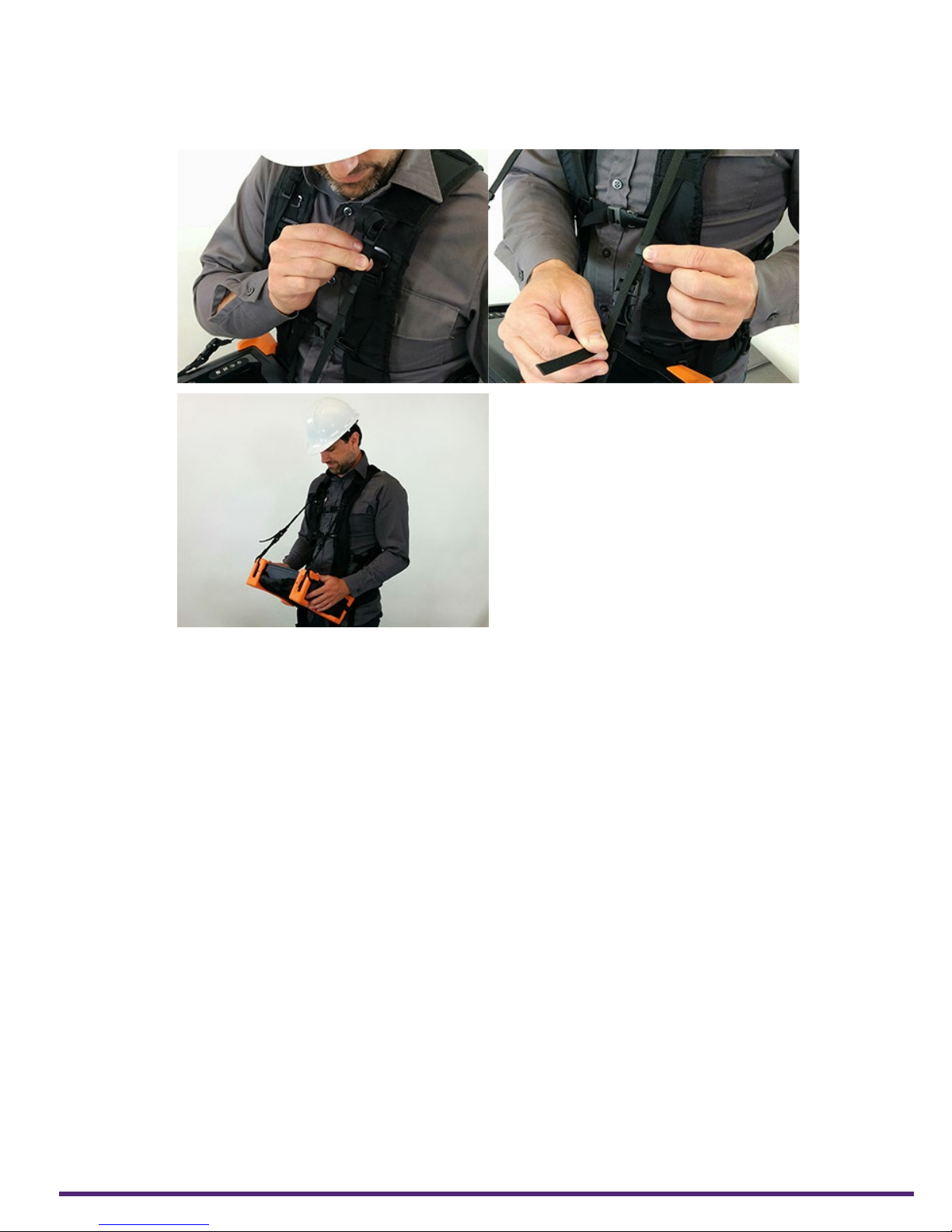
Using the Optional Harness
23. Repeat for the opposite shoulder anchor strap.
24. Tighten each shoulder anchor straps to achieve the desired view angle for Swift.
Figure A–16 Tightening shoulder anchor straps
| 68
 Loading...