

PHOTO
FACT*
Fold
er
9123 (Ch.
SILVERTONE
110.499),
9126 (Ch.
11O.499-2)
MODELS
9124
(Ch.llO.499-1),
2
K)
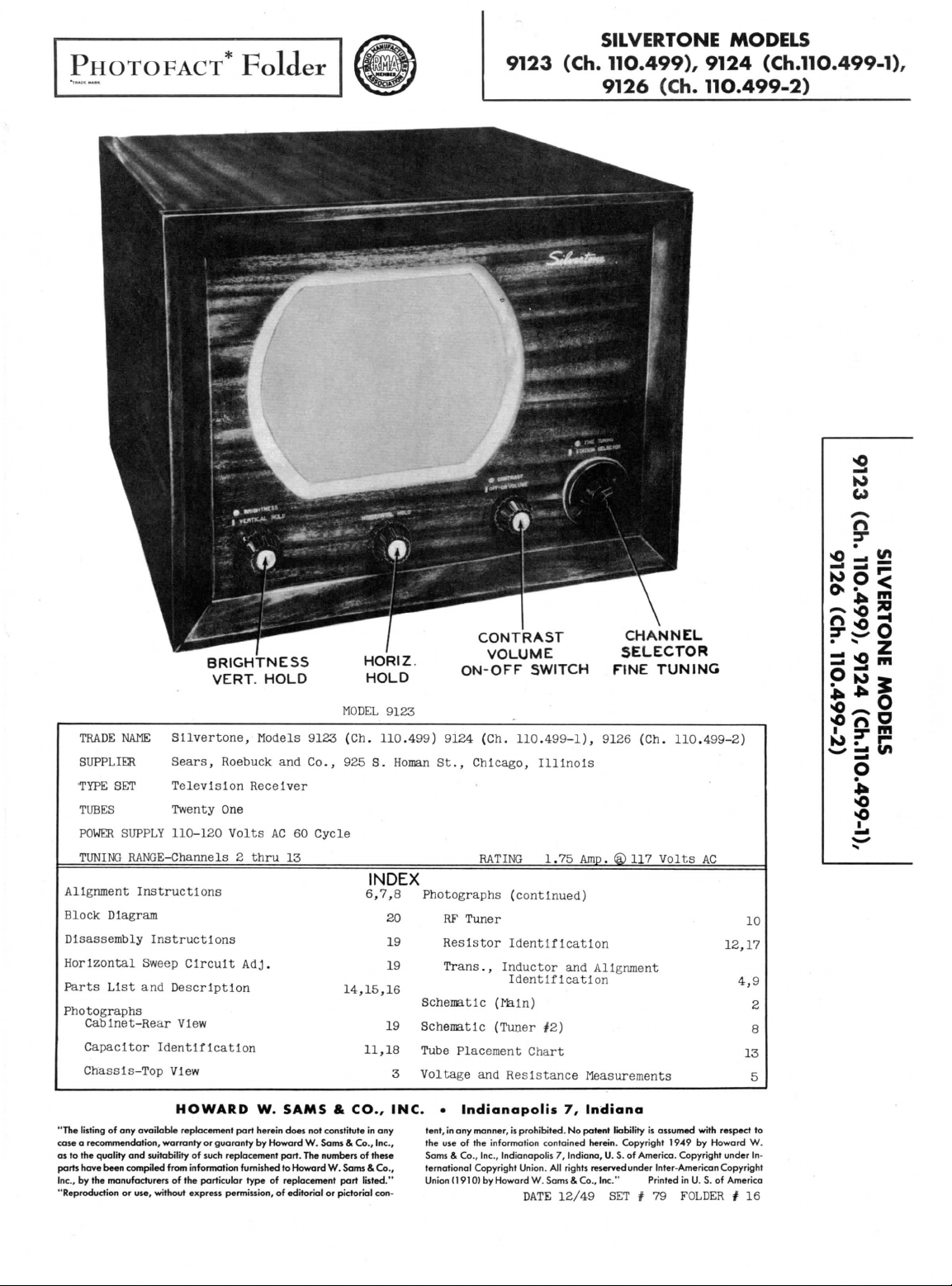
BRIGHTNESS
VERT.
TRADE NAME
SUPPLIER
'TYPE
TUBES
POWER
TUNING
Alignment
Block
Diagram
Sllvertone,
Sears,
SET
Television Receiver
Twenty
SUPPLY
110-120
Roebuck
One
Volts
RANGE-Channels 2 thru
Instructions
Disassembly Instructions
Horizontal Sweep Circuit
Parts
List
and
Description
Photographs
Cabinet-Rear View
Capacitor
Chassis-Top
Identification
View
HOLD
Models 9123 (Ch.
and
Co.,
AC 60
Cycle
15
RATING 1.75
Adj.
HORIZ.
HOLD
MODEL
9123
110.499)
925 S.
INDEX
6,7,8
14,15,16
11,18
CONTRAST
VOLUME
Homan
ON-OFF
9124 (Ch.
St.,
Chicago,
SWITCH
110.499-1),
Illinois
Photographs (continued)
20
19
19
19
RF
Tuner
Resistor
Trans.,
Schematic
Schematic
Identification
Inductor
Identification
(Main)
(Tuner
#2)
Tube Placement Chart
3
Voltage
and
Resistance Measurements
SELECTOR
FINE
9126 (Ch.
Amp. @ 117
and
Alignment
CHANNEL
TUNING
110.499-2)
Volts
AC
12,17
4,9
m
2
S
O
z
gc;
o
•
*
t^
10
2
8
13
5
"The
listing
of any
quality
and
been
compiled
manufacturers
or
use,
available
suitability
case a recommendation,
as
to the
parts have
Inc.,
by the
"Reproduction
HOWARD
replacement
warranty
from
of the
without
or
guaranty
of
such
information
particular
express
W.
part
herein does
by
replacement
furnished
type
permission,
SAMS & CO., INC. • Indianapolis
tent,
in
any
manner,
is
Howard
part.
to
Howard
of
replacement
of
editorial
not
constitute
W.
Sams & Co., Inc.,
The
numbers
W.
Sams & Co.,
part
or
pictorial
in any
of
these
listed."
con-
the
use of the
Sams & Co., Inc., Indianapolis
ternational Copyright Union.
Union
(1910)
prohibited.
information contained herein. Copyright
by
Howard
7,
Indiana
No
patent
liability
7,
Indiana,
rights
12/49
U. S. of
reservedunder
SET # 79
All
W.
Sams & Co., Inc." Printed
DATE
is
assumed with respect
1949
by
America. Copyright under
Inter-American Copyright
Howard
in U. S. of
America
FOLDER # 16
to
W.
In-

PAGE
2
A
PHOTOFACT STANDARD
©Howard
W.
THE
COOPERATION
RECEIVER
NOTATION
Sams
8.
Co.,
MAKES
Inc.
1949
OF THE
IT
POSSIBLE
SCHEMATIC
MANUFACTURER
TO
BRING
YOU
OF
THIS
THIS SERVICE
VERT. OSC.
2,
©»}6SN76T
VERT.
y6SN7GT(§)B
AMP
AUDIO
OUTPUT
I
H.V. RECTIFIER
/X\
1B3GT
n
ill
2
O
(Ch. 11O.499-1),
MODELS
SISSVHO
9124
110.499-2)
dOl
SILVERTONE
9126 (Ch.
M3IA
(Ch. 11O.499),
9123
PAGE
4
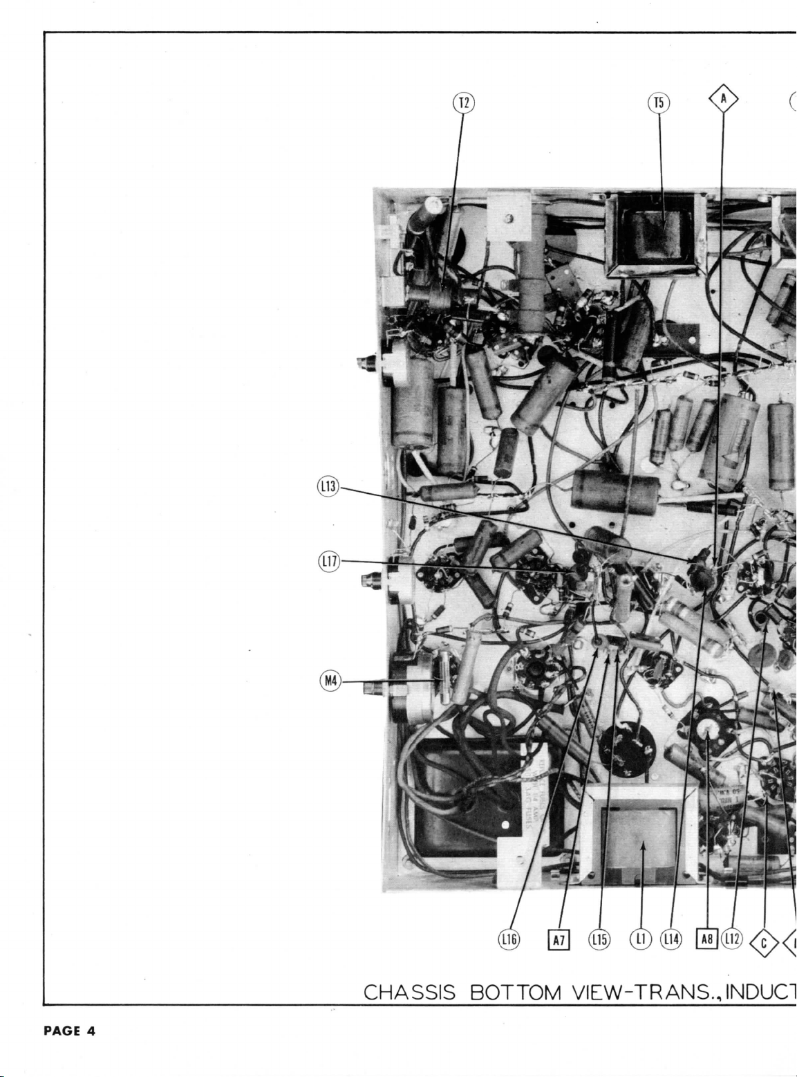
CHASSIS
BOTTOM VIEW-TRANS.JNDUCI
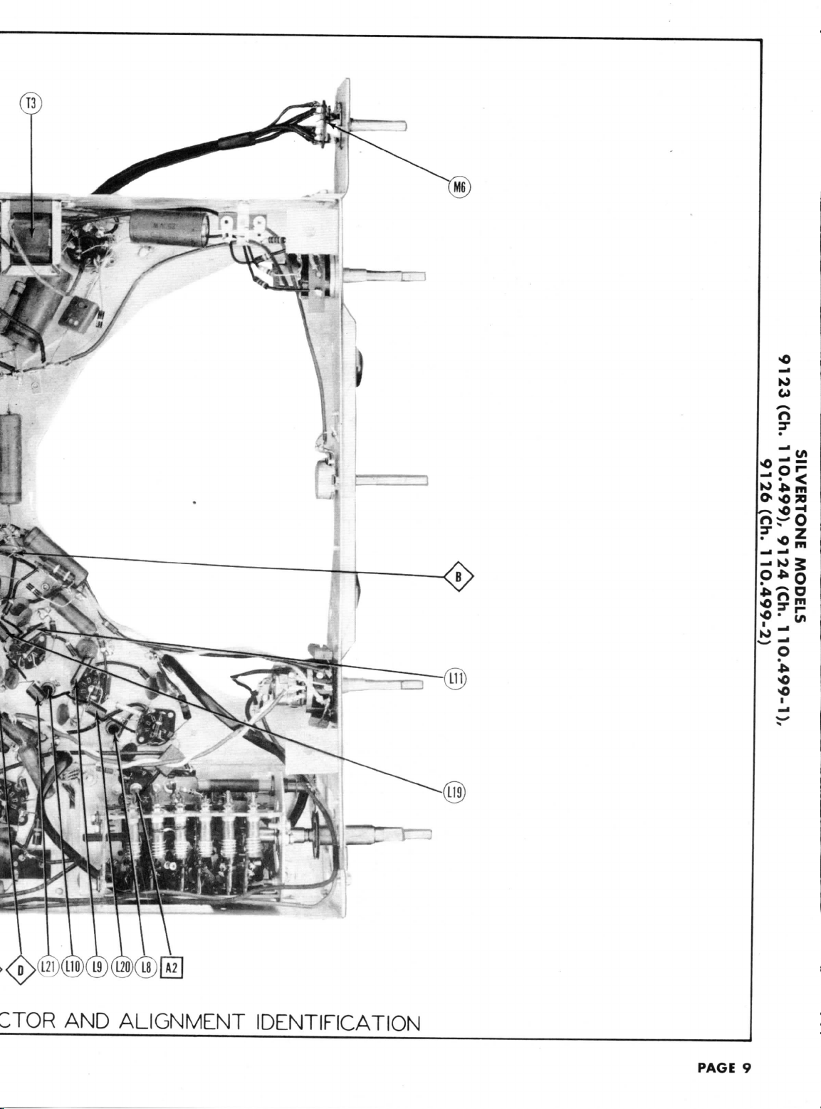
TOR AND
ALIGNMENT IDENTIFICATION
PAGE
9

9
Pin
02
*330KS2
CAP
»1002
02
»3002
TOP
MEASUREMENTS
RESISTANCE
AND
8
Pin
7
Pin
02
oa
47S
808
80S
6
Pin
MeE.
13002T 12002
1
MeE.
1
.22
13K2
I2K2
6J6
V 2V
ov
-4.6VDC
T
100K2
13002
T
100K2
.22
.22
02
T5.6K2
02
Me*.
T5.6K2
1.6
6J6
6AU6
3
V 4V 5V 6V7
.4VDC
.5VDC
?-3.6VDC
125VDC
.
.6VDC
12002
T
.22
02
OS!
Mee.
1.6
6AU6
126VDC
1.6M6E.
5
Pin
1.6M6K.
4
Pin
READINGS
OS!0202
3
Pin
RESISTANCE
.22
2
Pin
T4K2
Pin 1
T4K2
Tube
6J6
Item
V 1
Pin?
8
Pin
7
Pin
OV
6
Pin
-.SVDC
*10K2
.22
1002
680K2
10002
T
02
20K2
110002
10K2
7502
.22
02
10K2
.2ffl
02
7502
10002
OS
02
.22
1S2
OS
6AU6
6ALS
6AC7
8
V
215VDC
1VDC
-.5VDC
6.3VAC
128VDC
OV
155VDC
370KS2
020202
47K2
«26K2
.22
*3K2
.22
02
.22
39002
USE.
1
02
TlOKffi
470K2
12AU7
6AU6
V9
V 10
OV
DC
IV
OVOVOV
SVDC
5.
25VDC
MeE.
10
02
2202
02
Inf.
15K2
.22
470K2
15002
.22
150K2
33K2
»280K2
5.6K2
6002
02
.22
»7K2
33K2
MeE.
02
*18002
.22
2.2
02
Inf.
*82002
02
.22
02
02
MeE.
•
1
MeK.
»10K2
1
20K2
20K2
Inf.
02
20K2
Inf.
Inf.
33S2
12
Inf.
.52
inf.
PIN
202
11
Inf.
TlOOOffl
50K2
100K2
100K2
402
PIN
10
Inf.
47KSZ
OS
6T8
V 11
70VDC
-.6VDC
-.4VDC
.32
*3000
.32
Inf.
6V6GT
V 12
15002
02
MeE.
Mee.
•2.8Meg.
•1.5M6K.
4.7
4.7
MeE.
»27K!2
4.7M6E.
2
12AU7
6SN7GT
6AL5
V 15
V 13
V14
OV
SVDC
6.
ov •
6.3VAC
25VDC
10VDC
OV
-3.6VDC
100VDC
OV
12VDC
OV
245VDO
Inf.
»02
802
.22
Inf.
6BG6G
V 16
e
TOP CAP
250VDC
OV
-1.3VDC
208
20K2
PIN
»1502
.22
Inf.
»22K2
Inf.
Inf.
2500B
1B3GT
6W4GT
6X5GT
19
V 18
V
V17
OV
6.3VAC
410VDC
V20
175VDC
OV
OV.
VSO
20K2
270KS2
2 of
3 of V17
8 of V19
pin
pin
pin
Inf.
02
from
from
12LP4
5U4G
Measured
Measured from
Measured
V21
T
»
»
370VDC
340VDC
365VAC
volt-
to the
for
volts
117
at
maintained
voltage
Line
4.
20,000
at
are
Voltage measurements
DC
1.
minimum
both
given.
minimum.
are
vary according
set at
may
readings
service controls,
controls
readings
of the
readings.
reao«ingS.
age
age
1,000
at
measured
Voltage
AC
volt;
per
ohms
oh
maximum
and
setting
Where
Front panels
6.
5.
com-
direc-
pin to
clockwise
a
socket
In
from
otherwise stated.
socket.
are
counted
of
unless
are
values
bottom
negative
on
numbers
mon
tion
Measured
3.
2. Pin
3NO133A1IS
SlldOW
'(L-66fr'OU'H:»
VOLTAGE
5
Pin
4
Pin
3
Pin
VOLTAGE READINGS
2
Pin
1
Pin
Tube
Item
SVDC
§-4.
126VDC
128VDC
125VDC
-2.4VDC
-.SVDC
3VAC
ov
ov
ov
6.3VAC
6.3VAC
6.3VAC
60VDC
115VDC
85VDC
115VDC
60VDC
85VDC
6J6
6J6
6J6
1
V 3V
V
V2
.
6
6.3VAC
6.3VAC
0V
0V
0V
0V
0V
0V
0V0V0V
-.SVDC
-.7VDC
6AU6
6AU6
6AU6
6
4
V
V5
6.3VAC
6.3VAC
-1VDC
1.4VDC
6.3VAC
OV
-1.8VDC
SVDC
.
6.3VAC
1.4VDC
5
0V
-2VDC
0V
125VDC
12AU7
6AC7
6AL5
8
V9
V.7
V
OV
245VDC
OV
6.3VAC
0V
-.6VDC
6AU6
10
V
330VDC
OV
250VDC
OV
0V
-.4VDC
235VDC
avDc
.
6.3VAC
60VDC
140VDC
-
0V
-AOVDC
0V
6V6QT
6SN70T
6T8
12
V
V13
V 1 1
-1.4VDC
OV
6.3VAC
340VDC
.'7VDC
125VDC
6.3VAC
-1
OV
SVDC
.
10VDC
.2VDC
240VDC
12AU7
15V 16
V
410VDC
7
Measure
6.3VAC
280VDC
not
Do
.
OV
0V
6BG6G
6W4GT
17
V18
V
6.3VAC
-1.2VDC
SVDC
2.
6AL5
V14
12
165VAC
6.3VAC
OV
PIN
11
125VDC
135VDC
PIN
36SVAC
10
PIN
165VAC
340VDC
340VDC
AC
3V
6.
1VDC
370VDC
0V
0V
0V
1B3GT
6X5GT
V19
V20
Vacuum Tube Voltmeter
measure.
with
12LP4
5U4G
Taken
V21
& Do not
§
en
m
o
5

ALIGNMENT
INSTRUCTIONS
If
set is to be
voltage.
The
local
oscillator
DUMMY
ANTENNA
ilgh
grounded
shield floating
over
Low
side
sis.
Connect
horizontal deflection.
DUMMY
ANTENNA
Is
DUMMY
ANTENNA
.01MFD
.01MFD
horizontal deflection.
DUMMY
ANTENNA
.01MFD
.01MFD
horizontal deflection.
as
of
DUMMY
ANTENNA
Two
carbon
res.
the
High
grounded
shield floating
over
Low
side
Connect
two
alignment
High
(Grid)
Low
side
Use
frequency
High
(Grid)
Low
side
Connect
the
Connect a 1000MMF
possible.
Connect
the DC
The
signal
These
adjustments
alignment.
1202
Across
mlnals
each
"
ti
9.
"
10.
"
it
12.
ii
If
markers
channel.
are
Recheck
aligned
SIGNAL
GENERATOR
COUPLING
side
to un-
tube
mixer
tube
to
chas-
»
»
synchronized
SWEEP
GENERATOR
COUPLING
side
to un-
tube
mixer
tube
to
chassis
matched
Point
E as
SIGNAL
GENERATOR
COUPLING
side
to
pin
of
6AC7
to
chassis
"
modulated
SWEEP
GENERATOR
COUPLING
side
to pin 4
of
6AC7
to
chassis
synchronized
Probe
generator
are
SWEEP
GENERATOR
COUPLING
antenna
with
120S2
lead.
"
n
"
below
all
ALIGNMENT
with
tube
V3
GENERATOR
FREQUENCY
22.
(Unmod.
V2.
25.3MC
(Unmod.)
21.25MC
(Unmod.)
sweep
GENERATOR
FREQUENCY
24MC
(10MC
Sweep)
V2.
100KS2
(-1%}
shown
on the
GENERATOR
FREQUENCY
4.
4
(
Unmod . )
(V10)
signal
GENERATOR
FREQUENCY
4.
(V8).
(4SOKC
Sweep)
sweep
v
capacitor
of
VTVM
should
normally
GENERATOR
FREQUENCY
t er-
177MC
In
(10MC
Sweep)
183MC
(10MC
Sweep)
189MC
(10MC
195MC
(10MC
201MC
(10MC
Sweep)
207MC
(10HC
213MC
(10MC
high
Sweep
band
70% on any
the
picture tube
should
SIGNAL
SMC
)
voltage
SWEEP
resistors
schematic.
SIGNAL
SMC
"
SOUND
with
SWEEP
SMC
voltage
from
the
to the
be
terminated
very
SWEEP
Sweep)
Sweep
)
Sweep)
)
channel
channels.
INSTRUCTIONS—
be
removed
CHANNEL
Any
READ
removed,
during
VIDEO
3C
Probe
\n
point
"
"
OVERALL
VIDEO
from
the
signal generator
MARKER
GENERATOR
FREQUENCY
22.
2S.2MC
CHANNEL
Any
SMC
In
CHANNEL
Any
series
JC
Probe
?>
Common
sis.
JC
Probe
)>
Common
Joint
IF
ALIGNMEIv I USING
60%
modulation
MARKER
GENERATOR
FREQUENCY
4.
SMC
grid
Junction
stable
MARKER
GENERATOR
FREQUENCY
175.25MC
179.75MC
181.25MC
185.75MD
187.25MC
191.75MC
193.25MC
197.75M3
199.25MC
203.75MC
205.25MC
209
211.25MC
215.75MC
make
CHANNEL
Any
RF
«.
MIXER
from
the
signal generator
of the
of
R24
with a resistance equal
and
alignment
CHANNEL
7
8
9
10
11
12
.75MC
13
slight
CAREFULLY
remove
IF
Alignment
IF
ALIGNMENT
CONNECT
VTVM
to
Point
to
Point
<§>
n
«
IF
RESPONSE CHECK
Vert . Amp . to
Point A Low
side
from
Point
CONNECT
VTVM
to
Point
to
chas-
to
Point
to
Point
<^>
FM
SIGNAL
and
450KC
Vert.
Polnt^>
side
Vert . Amp . to
PolntOv
side
ALIGNMENT
first
video amplifier
and
C31,
should
Vert.
lOKffi
Low
side
sis.
adjustment
BEFORE
the
horizontal
ADJUST
A1,A2
A3,A4
A9
to the
CONNECT
SCOPE
to
chassis.
C
to
ADJUST
A5,A6,
A7
A8
GENERATOR
sweep.
CONNECT
SCOPE
Amp.
to
Low
to
chassis.
Low
to
chassis.
-TUNER*
to the
common
to
not be
CONNECT
SCOPE
Amp.
thru
to
Polnt<3pt
to
"
"
"
n
"
n
of
A10, All,
ATTEMPTING
to
prevent erroneous Indications.
Adjust
Adjust
horizontal Input
chassis.
Adjust
Adjust
negative reading
side
with
AND
Use
A5.A6,
A7
A5.A8
horizontal
(6AU6,
to
chassis.
Its
output
attempted
A10,A11
A12,A13
chas-
ALIGNMENT
oscillator
for
maximum
for
MINIMUM
ADJUST
Check
with
SLIGHTLY
for
The
for
for
of the
step
7.
OSCILLOSCOPE
13CX\
sawtooth
ADJUST
Disconnect
Adjust
amplitude
Reconnect
Adjust
center
Fig
maximum
of
V4) to
Set
Impedance
unless
ADJUST
Adjust
response
above
Check
Fig
A12,
and A13
tube
V15 to
disable
REMARKS
deflection.
n
deflection.
of the
oscilloscope
REMARKS
for
response
markers
retouch
optimum
Junction
maximum
zero reading. A positive
will
correct
voltage
A5,
and
stabilizer
AS
so
of
crossover
3.
SLIGHTLY
amplitude
crossover
Input
of the
chassis
contrast
(usually
they
for
as per Fig 4
70%.
for
response curve
4.
as per
as
shown.
If
Al,
these
two
A2, A3, and A4
response.
of
REMARKS
deflection.
be
obtained
setting.
stabilizer
A6,
In
scope
REMARKS
and A7
symmetry
4.5MC
retouch
and
lines.
Continue
capacitor
ror
capacitor
marker
lines
stralghtness
oscllloscooe
Keen
leads
control
to
50
known
REMARKS
ohms)
with
are
approximately
resistors
for
as per
A5
read
to be out
flat
as per
"
"
a
"
9
with
channel
selector
the
high
for
Fig
1.
necessary
and
on
either
C4.
maximum
Fig
C4.
occurs
as per
for
for
short
-3V
top
markers
on
that
2,
at
PAGE
6

DUMMY
ANTENNA
Two
14.
carbon
res.
15.
16.
17
18.
11
channel.
DUMMY
ANTENNA
Two
carbon
res.
21.
23.
24.
26.
28.
29.
encountered.
is
imately
Across antenna
1202
minals
each
"
"
"
"
markers
Recheck
Across
1202
minals
In
"
"
"
ri
11
"
"
n
"
n
*
Wave traps
at
maximum.
the
SWEEP
GENERATOR
COUPLING
with
1202
lead.
11
»
n
'
are
below
70% on any
all low
SWEEP
GENERATOR
COUPLING
antenna
with
lead.
1302
each
"
"
"
"
n
"
*
n
n
A32 and A33 are
With
the
Adjust
same relative
SWEEP
GENERATOR
FREQUENCY
85MC
ter-
(10MC
In
Sweep)
79M3
(10MO
Sweep)
69MC
(10MC
Sweep
63MC
(10MC
Sweep)
57IE
(10MC
Sweep)
channel
band
channels.
SWEEP
GENERATOR
FREQUENCY
ter-
aisrc
(10MC
Sweep)
207MC
(lOtC
Sweep)
201PE
(10MC
Sweep)
195MC
(10MC
Sweep)
189te
(10MC
Sweep)
183MC
(10JK
Sweep)
177MC
(10MC
Sweep)
85tK
(10MC
Sweep)
79M3
(10MC
Sweep)
69MS
(lone
Sweep)
63MC
(10tK
Sweep)
S7MO
(10M3
Sweep
used
ASS
for
for
receiver tuned
A32 and
position.
GENERATOR
)
)
specific
to the
minimum
Turn
MARKER
FREQUENCY
B3.25IC
87.75MC
77.25IC
81.75MC
67.25MC
71.7SMC
61.25MC
65.75IC
55.25MD
59.75IC
make
slight
OSCILLATOR
MARKER
GENERATOR
FREQUENCY
211.25MC
215.75MC
305.25MC
209.75MC
199.25MC
80S.75MC
193.25MC
197.75MC
187.35MC
191.75MC
181.2SMC
185.75MC
175.25IC
179.75MC
83.25M:
87.75M)
77.25M3
81.75M3
67.25W;
71.75113
61.2SM3
65.75IE
55.25MC
59.75MD
WAVE
TRAP ADJUSTMENT
types
channel having
interference
one
core
CHANNEL
Vert.
6
10K2
Low
sis.
5
4
3
2
adjustment
ALIGNMENT-TUNER*!
CHANNEL
13
Vert.
Point<^
side
12
11
10
9
8
7
6
5
4
3
2
of
interference
the
1/2
in the
turn, adjust
CONNECT
SCOPE
Amp.
thru
to
Polnto?
side
to
chas-
"
"
"
"
of
A14,
A1S
CONNECT
SCOPE
Ajnp.
"to
Low
to
chassis.
n
n
"
n
if
n
**
n
and
interference,
picture
the
A14,A15
A16,A17
A16,
A20
A21
A24
A25
A26,A27
A28
A29
A30
A31
their
and
other
ADJUST
ADJUST
A18,A19
A22
A23
set
for
Adjust
for
response
as per
above
70%.
Check
for
and A17
alignment
sound, keeping
with
Adjust
for
Fig 5
with
fine
will
tuning control until
minimum
interference.
REMARKS
approximately
Fig. 4 with markers
response
as per Fig 4.
'
H
"
channel
selector
REMARKS
response
markers
curve
as
"
n
n
*
n
n
it
n
depend upon
the
cores
flat
on
as per
shown.
the
interferenc
at
approx-
top
that
type
2
Jo
^x
ft
3-
•
5
— if
* > 2
o
J*
•o
NOT
MORE
SOUND
MARKER t MARKER
THAN
3OS
FIG.
VIDEO
4
FIG.
5
RF
OSCILLATOR
ALIGNMENT
B^GET
POINTS

The
sweep generator output lead should
Set the
Complete
same
amount
noted™hat
I?
adjustment
to
use
t™
ohamel
adjustment screw
DUMMY
ANTENNA
Two
1202
31.
carbon
res.
32.
ALIGNMENT INSTRUCTIONS CCONTJ
contrast control
SSclllatS?
for a
this
of
individual
oscillate?
GENERATOR
Across antenna terminals
In
each
alignment
majority
Is
an all
A504
will
channel
adjustments
is
accessible through
SWEEP
COUPLING
with
1208
lead.
to
measure 1 volt
may not be
of the
channel
not
bring
oscillator
are
SWEEP
GENERATOR
FREQUENCY
207MC
(10IK
Sweep
213MC
(10MC
Sweep
207MC
(10MC
Sweep
201MC
(lore
Sweep
19bMC
(10MC
Sweep)
18SMC
(10MO
Sweep
183r£
(10MC
Sweep
177MC
(10MC
Sweep)
85MC
(10MC
Sweep)
79MC
(10MC
Sweep)
69I1C
(10MC
Sweep
63MD
(10MC
Sweep)
57MC
(10MC
Sweep)
RF
8.
OSCILLATOR
be
channels,
oscillator
all
channels within
adjustment
reached,
this
MARKER
GENERATOR
FREQUENCY
205.25MC
209.75MC
)
211.25MC
215.75MC
)
205.25MC
209.75MC
)
199.25MC
203.75MC
)
19B.iibrE
197.75MO
187.25*
191.75MC
)
181.25rE
185.75MC
)
175.25MC
179.75MC
83
.25MC
87.75MC
77.25MC
81.75IC
67.25rE
71.75MC
)
61.25MC
65.75MC
55.25MC
59.75MO
ALIGNMENT
terminated
on a
necessary.
It
may be
circuit
through a hold
hole
with
VTVH
connected between
If the
possible
adjustment
for
as the
channel switch
CHANNEL
12
13
12
11
10
9
8
7
6
5
4
3
2
CTUNER*2)
Its
characteristic Impedance, usually
oscillator seems
to
correct them
and
range
to the
CONNECT
SCOPE
A. Low
to
should
of the
right
Is
chassis.
the
each channel that
Just
Vert . Amp . to
Point
side
pin
5 of V8 and
to be
In
not be
fine
tuning
is off
frequency (step
of the
turned
to
ADJUST
A501,
A502,
A503
A505
A506
A507
A508
A509
A510
A511
A512
A513
A514
A515
A516
chassis.
off
frequency
one
step using
adjusted
control
channel switch shaft.
each channel.
Adjust
for
to
Fig
S.
Adjust
to
in
Fig 5.
50
approximately
A504
for any
Individual
It
will
32).
REMARKS
response curve similar
place markers
ohms.
It
be
necessary
The
The
the
should
be
channel.
Individual
correct
as
shown
PAGES
A
PHOTOFACT STANDARD
©Howard
W.
RF
NOTATION
Sams
8,
Co.,
SCHEMATIC
Inc.
1949
TUNER
*2

RF
TUNER-LEFT
SIDE
PAGE
1O
RF
TUNER-RIGHT
SIDE

PAGE
18
CHASSIS
BOTTOM
VIEW-CAI

CM)
(C6!)
v. y v
./
;APACITOR
IDENTIFICATION
PAGE
11

PAGE
12
CHASSIS
BOTTOM
VIEW-RES

o-
t-
Ki
CJ
n
o
•
Jh
LSISTOR
IDENTIFICATION
PAGE
17

BOTTOM
VIEW
TUBE PLACEMENT CHART
CC16
'MD)
I
'(66fr'OL
'H3)
L
'(L-66fr'OL
snaow
O

ITEM
VIA
V2
V3
V4
V5
V6
V7
V8
V9
V10
Vll
V12
V13
V14
V15
V16
V17
V18
V19
V20
V21A
ITEM
CIA
C2A
C3
C4
C5A
06
C7
C8
C9
CIO
Oil
012
CIS
014
015
C16
C17
018
019
C20
C21
C22
C23
C24
025
C26
027
C28
C29
C30
031
C32
033
C34
035
C36
037
038
039
C40
C41
C42
C43
C44
C45
C46
C47
048
049
C50
C51
C52
C53
C54
055
No.
B
No.
B
B
C
B
C
D
RF
Amp.
RF
Amp.
Mixer
Oscillator
1st
Video
End
Video
3rd
Video
Video
Rect.
Video
DC
Rest.
Sep.
-Sync.
Pbase
Sound
Ratio
Amp.
Audio
Vert.
Amp.
Hor.
Phase
Hor.
Osc,
Hor. Output
Damper
HV
Rectifier
LV
Rectifier
LV
Rectifier
Picture
Picture
B
RA
CAP.
40
40
40
20
10
500
1
40
20
10
10
100
10
10
1500
270
270
1.5
1.5
.68
5
2.2
1500
22
1500
10
4.7
4.7
1500
1500
68
270
5000
5000
5000
100
.1
5000
5000
100
5000
5000
5000
100
100
5
10000
.01
470
680
67
47
.1
22
390
5000
.02
.001
3300
.05
.005
USE
IF
Amp.
IF
Amp.
IF
Amp.
Det.4
AGO
Amp.
-Sync.
Inverter
IF
Amp.
Det.-AF
Output
Osc.-Vert
Det.
Tube
Tube
ING
SILVERTONE
VOLT
450
A20126
450
250
A20127
250
150
6
P20128
SO
P20129
450
A20125
450
450
450
25
P20130
500
P19109
P19109
P19109
P19110
400
P19111
P19109
P19109
P19110
P19109
P19109
P19109
P19110
P19110
P19114
P19113
400
P19116
500
P19105
500
P19104
500
600
P19121
500
P1990
P19117
500
P19109
600
P19115
600
P19103
P19118
200
P19119
600
P1987
TUBES
REPLACEMENT
SILVERTONE
PART
No.
6J6
6AG5
6J6
6J6
6AU6
6AU6
6AU6
6AL5
6A07
12AU7
6AU6
6T8
6V6GT
6SN7GT
6AL5
12AU7
6BG6G
6W4GT
1B3GT
6X5GT
5U4G
12LP4
10BP4
Capacity
values
and
Paper Capacitors,
PART
No.
AFH88J
AFH84F2D
PRS6/500
E26E39
AF8422J
PRS50/100
1468-00025
1467-005
1467-005
1467-005
1468-0001
P488-1
1467-005
1467-005
1468-0001
1467-005
1467-005
1467-005
1468-0001
1468-0001
1468-000005
P488-01
P488-01
1468-0005
1469-00005
P688-1
1468-000025
1468-0004
1467-005
P688-02
P688-001
P288-05
P688-005
(SYLVANIA
DATA
STANDARD
REPLACEMENT
6J6
6AG5
6J6
6J6
6AU6
6AU6
6AU6
6AL5
6AC7
12AU7
6AU6
6T8
6V6GT
6SN7GT
6AL5
12AU7
6BG6G
6W4GT
1B3GT
6X5GT
5U4G
1SLP4
10BP4
given
REPLACEMENT
AEROVOX
PART
No.
CAPACITORS
in the
rating
and in
mmfd.
DATA
CORNELL-
DUBILIER
PART
No.
UP4445
UP43145C
BRH605
BBR1-50
UP421145
BRH251A
5W5T25
1D5D5
1D5D5
1D5D5
5W5T1
GT4P1
1D5D5
1D5D5
5W5T1
1D5D5
1D5D5
1D5D5
5W5T1
5W5T1
5W5V5
GT4S1
GT4S1
5W5T5
1W5T7
5R5Q5
GT6P1
5W5Q25
5W5T4
1D5D5
GT6S2
GT6D1
GT2S5
GT6D5
or
RMA
BASE
TYPE
7BF
7BD
7BF
7BF
7BK
7BK
7BK
6BT
8N
9A
7BK
9E
7AC
8BD
6BT
9A
SET
400
30
6S
5T
12D
12D
column
lor
PART
§
NPOK-10
NPOK-10
GP2L-0015
GP2K-270
GP2K-270
NPOK-5
GP2L-0015
GP1K-22
GP2L-0015
NPOK-10
NPOK-4.7
NPOK-4.7
GP2L-0015
GP2L-0015
GP1K-270
811-005
811-005
811-005
GP1K-100
811-005
811-005
GP1K-100
811-005
811-005
811-005
GP1K-100
GP1K-100
NPOK-5
821-01
GP2-335-01
GP2K-470
GP2K-680
NPOM-50
GP1K-22
GP2K-390
811-005
GP2L-001
GP2M-0033
GP2M-005
Equivalent)
Used
In
Used
In
Used
In
Used
In
Used
In
are in
ERIE
No.
and
mid.
Ceramic
SPRAGUE
PART
TVL-64
D9041
TVA-4
TVA-11
TVL-40
TVA-8
1FM-325
29C1
2901
2901
1FM-31
TM-1
29C1
29C1
1FM-31
2901
29C1
2901
1FM-31
1FM-31
MS-55
3601
TM-11
1FM-35
1FM-37
MS
TM-1
MS-425
1FM-34
2901
TM-12
TM-21
TM-15
TM-2S
Mica
Tuner
ft
Tuner
C2
Tuner
ft
models
9124
model
9123
lor
Electrolytic
Capacitors.
No.
-
Filter
i
Filter
-
Filter
•
Filter
* V.
Bias
Stabilizing
-
Filter
•
Decoupling
A
Vert.
Vert.
Vert.
Fixed
Fixed
AGC
RF
Coupling
RF
Coupling
Neutralizing
Neutralizing
RF
Coupling
RF
Coupling
RF
Coupling
RF
Decoupling
Fixed
Osc.
Fixed
Osc.
Osc. Feedback
Filament Bypass
Mixer
Fixed
IF
Coupling
AGC
1st V. IF
1st V. IF
IF
Coupling
AGC
2nd V. IF
2nd V. IF
IF
Coupling
3rd V. IF
3rd V. IF
3rd V. IF
IF
Coupling
IF
Coupling
V.
Diode Filter
Bias Filter
AGC
V.
Amp.
V.
Amp. Cath. Bypass
Tlxed
-45
rixed
Video
DC
Res . Plate
S. IF
S . IF
S. IF
Diode
De-emphasis
Audio Coupling
Audio
NOTES
and
9126
IDENTIFICATION
AND
INSTALLATION
Amp.
Screen
Filter
Cap.
Osc.
Dec.
Output
Dec.
Output Cath. Byp.
Trimmer
Trimmer
Filter
Trimmer
Decoupling
Trimmer
Feedback
Decoupling
Trimmer
Filter
Decoupling
Fll.
Bypass
Filter
Decoupling
Fll.
Bypass
Cath.
Bypass
Decoupling
Fll.
Bypass
»
Filter
Cath.
Bypass
Trimmer
Trimmer
Coupling
Coupling
Screen Bypass
Decoupling
Load
Coupling
Cap.
Bypass
t
CODES
NOTES
Byp.
ITEM
No.
056
.01
057
.005
058
.005
059
.01
C60
.002
061
.005
062
.005
063
4700
064
.1
065
.25
066
.001
067
.001
068
.01
069
.01
070
.1
071
.005
C72
.1
073
390
074
3900
075
390
076
270
077
36
078'
36
079
.05
080
.25
081
.25
082
220
083
.25
084
500
085
.1
086
.02
087
.02
*
Some
t
Some
*
Used
series
§
Omit
ITEM
No.
R1A
100K2
B
1
Shaft
C
R2
50K2
10002
R3A
250K2
B
R4
15002
R5
50002
R6
2.5Meg.
t
Additional
ITEM
No.
P,7
1502
R8
1502
R9
10002
RIO
47002
Rll
47002
R12
10002
R13
1
R14
10K2
R15
1000B
R16
1502
R17
47002
R18
472
R19
lOOKffl
R20
100K2
R21
10K2
R22
822
R23
iooa
R24
3302
R25
82002
R26
822
R27
1002
R28
1
R29
82002
R30
1002
R31
1002
R32
680K2
R33
39K2
R34
82002
R35
10002
R36
1202
R37
10K2
R38
68002
R39
47K2
R40
47K2
R41
22K2
R42
22002
R43
270KS2
R44
47K2
R45
820K2
R46
1
R47
39002
R48
39002
R49
39002
RATING
CAP.
VOLT
600
600
600
600
600
600
600
500
600
600
600
600
600
600
600
600
200
500
500
500
500
1500
1500
600
400
600
2500
600
10000
600
600
600
models
models
only
parallel
bypass
RATING
RESIST-
ANCE
Meg.
End
RATING
RESISTANCE
Meg.
Meg.
20%
Meg.
SILVERTONE
P1988
P1987
P1987
P1988
P19101
P19120
P
P1992
P191S1
P19108
P1991
P1991
P1988
P1988
P19100
P1987
P19111
P19122
P19107
P199S
P1994
P19135
P19135
P1996
P1995
P19108
P19136
P19108
P1998-1
P1989
P19106
P19106
use
use
In
models
section.
WATTS
i
J,
i
b
4
\T
^
parts
WATTS
4
i
i
i
i
i
i
i
4
X
4
1
£
X
7
^
1
2
2
2
4
X
X
4
i
4
PARTS
PART
No.
19
120
120MMF
In
39IW
in
this
with
combination
SILVERTONE
PART
No.
1
f
A24100
\
A24101
A2499
P2525
P2523
P2524
DATA
to be
used
REPLACEMENT
SILVERTONE
PART
P23108
P23148
P23109
P23110
P23111
P23148
P23109
P23112
P23111
P23109
P23109
P23113
P23107
P23111
P23114
P23115
P23101
P23117
P23116
P23116
P23100
P23128
P23129
P23131
P23130
P23112
P23132
P23132
P23132
LIST
AEROVOX
PART
No.
P688-01
P688-005
P688-005
P688-01
P688-002
P688-005
P688-005
1467-005
P688-1
684-25
P688-001
P688-001
P688-01
P688-01
P688-1
P688-005
P288-1
1468-0004
1468-0004
1468-00025
P688-05
P488-25
684-25
684-25
P688-1
P688-02
P688-02
this
application.
application.
12
inch
in
this
IRC
PART
fBll-128
Bll-137
(E187
Qll-123
Qll-114
Qll-239
with
No.
BTS-10K
BTS-1000
BTS-680K
BTA-39K
BTS-8200
BTS-1000
AB-10K
BT-1-6800
BT-2-47K
BT-2-47K
BT-2-22K
BTS-2200
BTS-270K
BTS-47K
BTS-820K
BTS-1
BTS-3900
BTS-3900
BTS-3900
AND
CAPACITORS
REPLACEMENT
olcturQ
No.
i
"Concentriklt".
DATA
CORNELL-
DUBILIER
PART
No.
GT6S1
GT6D5
GT6D5
GT6S1
GT6D2
GT6D5
GT6D5
1D5D5
GT6P1
GT6P25
GT6D1
GT6D1
GT6S1
GT6S1
GT6P1
GT6D5
GT2P1
5W5T4
5W5T4
5W5T25
GT6S5
GT4P25
GT6P25
GT6P25
GT6P1
GT6S2
GT6S2
tube.
application.
CONTROI
OAROSTAT
PART
i
10-1500
M-19-S
No.
i
RESISTOI
DATA
IRC
PART
No.
Meg.
ALL F
So
RF C
RF C
Bia£
RF
RF
RF
MlXE
Mixe
Mlxs
Decc
Osc.
Osc.
Osc.
Osc.
1st
1st
1st
AGO
2nd
2nd
2nd
AGC
3rd
3rd
3rd
AGO
V011
Vidi
Bla:
Par;
Vldf
Vldi
Fir
Fll-
Blei
Pic'
DC
DC
Vol1
Syni
Sync
Sym
Sync
C(
GP2
GP2
GP2
GP2
GP2
QP2
GP2
GP2
GPS
GP£
GP£
GP£
GPZ
GPi
GP£
GPE
41C
I
I
I
I
!
I
PAGE
14

NOTES
sr
11
3r
K
er fi
31 s 9124
and
21
91S3
sr
Electrolytic
c
Capacitors.
-
Filter
*
•
•
Filter
* V,
Bias
-
Filter
Vert. Output Dec.
Vert. Output Oath. Byp.
Fixed
Fixed
AGO
RF
RF
Neutralizing
Neutralizing
RF
RF
RF
RF
Fixed
Osc.
Fixed
Osc.
Osc. Feedback
Filament Bypass
Mixer
Fixed
IF
AGO
1st V. IF
1st V. IF
IF
AGO
2nd V. IF
2nd V. IF
IF
3rd V. IF
3rd V. IF
3rd V. IF
IF
IF
V.
Bias
AGO
V.
V.
ixed
ixed
Video
X3
S. IF
S. IF
S. IF
)e-emphasis
Audio Coupling
Audio
9126
§
IDENTIFICATION
INSTALLATION
Filter
Filter
Amp.
Filter
Decoupling
Vert. Osc. Dec.
Trimmer
Trimmer
Filter
Coupling
Coupling
Coupling
Coupling
Coupling
Decoupling
Trimmer
Decoupling
Trimmer
Feedback
Decoupling
Trimmer
Coupling
Filter
Coupling
Filter
Coupling
Coupling
Coupling
Diode
Filter
Filter
Filter
Amp. Cath. Bypass
Amp.
Cath.
Trimmer
Trimmer
Coupling
Res. Plate Bypass
Coupling
Screen Bypass
Decoupling
ode
Load Cap.
Coupling
CODES
AND
NOTES
Screen
Byp.
Decoupling
Fil.
Bypass
Decoupling
Fll.
Bypass
Cath. Bypass
Decoupling
Fil.
Bypass
*
Bypass
T
PARTS
RA1
CAP.
.01
.005
.005
.01
.002
.005
.005
4700
.1
.25
.001
.001
.01
.01
.1
.005
.1
390
3900
390
270
36
36
.05
.25
.25
220
.25
500
.1
.02
.02
Some
models
T
Some
models
Used
onlj
series
Omit
byps
RESIST-
ANCE
100K2
1
Meg.
B
Shaft
C
End
^OKO
loooa
250KB
15002
50002
2.5Meg.
Additional
RESISTANCE
1502
1502
10008
47002
47002
10002
1
Meg.
10KS
10008
1502
47002
472
lOOKffi
100K2
10K2
822
1008
3302
82002
828
icoa
1
Meg.
82002
iooa
1002
680K2
39K8
82002
10002
1202
10K2
6800S
47K2
47K2
22K2
2206a
270Ka
47K2
820K2
1
Meg.
39002
3900a
39002
ING
VOLT
600
60
60
60
60
60
60
50
60
60
60
60
60
60
600
60
20
50
50
50
500
15
15
60
400
60
25000
600
1060)00
600
60
pa
RATING-
RATING
80%
0
0
0
0
0
0
0
0
0
0
0
0
0
0
0
0
0
0
00
00
0
0
0
use
use
In
rallel
ss sec
WATTS
^
I
X
n
4
parts
me
SILVERTONE
PART
No.
P1988
P
1987
1987
P
P
1988
P
19101
P
19120
P
19120
P
1992
P
19121
P
19108
P
1991
P
1991
P
1988
P
1988
P19100
P
1987
P
19111
P
19122
P
19107
P
1993
P1994
P
19135
P
19135
P
1996
P1995
PP19108
19136
P19108
P
1998-1
P
1989
P19106
P
1M106
120MMF
39MMF
dels
with
combination
tlon.
SILVERTON
PART
\
A24100
P2625
P2523
P2524
to be
EILVERTONE
WATTS
j.
X
£
X
£
i
I
i
i
i
X
7
1
2
2
2
i
X
I
i
^
i
i
ITEM
No.
056
057
058
059
060
061
062
063
C64
065
066
067
C68
069
C70
C71
072
073
074
075
076
077
078
C79
080
,
081
082
083
084
085
086
087
*
•t
ITEM
No.
R1A
R9
ITEM
No.
P,7
R8
R9
RIO
Rll
R12
R13
R14
R15
R16
R17
R18
R19
R20
R21
R22
R23
R24
R25
R26
R27
R28
R29
R30
R31
R32
R33
R34
R35
R36
R37
R38
R39
R40
R41
R42
R43
R44
R45
R46
R47
R48
R49
P688-01
P686-005
P688-005
P688-01
P688-002
P688-005
P688-005
1467-005
P688-1
684-25
P688-001
P688-001
P688-01
P688-01
P688-1
P688-005
P288-1
1468-0004
1468-0004
1468-00025
P688-05
P488-25
684-25
684-25
P688-1
P688-02
P688-02
in
this
In
this
12
REPLACEMENT
No.
used with
REPLACEMENT
PART
No.
P23108
P23148
P23109
P23110
P23111
P23148
P23109
P23112
P23111
P23109
P23109
P23113
P33107
P23111
P23114
P23115
P23101
P23117
P23116
P23116
P23100
P23128
P23129
P23131
P23130
P23112
P23132
P23132
P23132
LIST
CAPACITORS
REPLACEMENT
AEROVOX
PART
No.
application.
application.
Inch
picture
in
this
DATA
IRC
PART
No.
rBll-128
1B11-137
(E187
i
on
i?3
Qll-114
CJ11-239
"Concentrlkit"
DATA
BTS-10K
BTS-1000
BTS-680K
BTA-39K
BTS-8200
BTS-1000
AB-10K
BT-1-6800
BT-2-47K
BT-2-47K
BT-2-22K
BTS-2200
BTS-270K
BTS-47K
BTS-820K
BTS-1
BTS-3900
BTS-3900
BTS-3900
AND
DATA
CORNELL-
DUBILIER
PART
No.
GT6S1
GT6D5
GT6D5
GT6S1
GT6D2
GT6D5
GT6D5
1D5D5
GT6P1
GT6P25
GT6D1
GT6D1
GT6S1
GT6S1
GT6P1
GT6D5
GT8P1
5W5T4
5W5T4
5W5T25
GT6S5
GT4P25
GT6P25
GT6P25
GT6P1
GT6S2
GT6S2
tube.
application.
CONTROLS
CLAROSTAT
PART
No.
i
i
10-1500
M-19-S
RESISTORS
IRC
PART
No.
ALL
Meg.
DESCRIPTIONS
CCONTO
ERIE
SPRAGUE
PART
PART
No.
GP2-335-01
G
P2M-005
G
P2M-005
0
P2-335-01
G
P2H-002
G
P2M-005
G
P2M-005
G
P2M-0047
G
P2L-001
G
P2L-001
G
P2-335-01
G
P2-335-01
G
P2M-005
G
P2K-390
G
P2K-390
GP2K-270
4
10-500
S
ome
models
Brightness
Vertical
Attach
Horl7, . Hold
Contrast Control, Tapped ® 7502,
Volume Control
Focus Control
Vert. Linearity Control
Height
RESISTORS
RF
Grid
RF
Grid
Bias
Filter
RF
Plate
RF
Plate
RF
Decoupling
Mixer
Grid
Mixer
Grid Shunt
Mixer
Decoupling
Decoupling
Osc. Plate
Osc.
Cathode
Osc.
Grid
Osc.
Grid
1st
Video
1st
Video
1st
Video
AGC
Network
2nd
Video
2nd
Video
2nd
Video
AGC
Network
3rd
Video
3rd
Video
3rd
Video
AGC
Diode
Voltage
Divider
Video
Det.
Bias
Network
Parasitic
Video
Amp. Plate (Wire Wound)
Video
Amp. Plate
Filter
Filter
Bleeder
Picture
Tube Grid
DC
Rest.
Load
DC
Rest.
Load
Voltage
Divider
Sync. Sep.
Sync. Sep. Cathode
Sync. Sep. Plate
Sync. Sep. Plate
No.
Audio
TM-11
TM-25
Output
TM-25
Output
TM-11
Sync.
TM-28
Integrator
TM-25
Integrator Net.
TM-25
Integrator Net.
Vert.
1FM-25
Vert.
TM-1
TC-2
Vert.
TM-21
Hor.
TM-21
TM-11
TM-11
TM-1
TM-25
TM-1
1FM-34
1FM-34
1FM-325
TM-15
TC-2
TC-2
TC-2
TM-1
TM-12
TM-12
use
four
Control-Front ) Dual
Hold - Rear
per
instructions
Control
Control
IDENTIFICATION
ARE t 10%
IF
Grid
IF
Cathode
IF
Decoupling
IF
Grid
IF
Cathode
IF
Decoupling
IF
Grid
IF
Cathode
IF
Decoupling
Load
Diode
Load
Supp.
Grid
Sync.
Hor.
Sync.
AFC
Filter
AFC
Filter
AFC
Feedback
Hor.
Sync.
Hor.
Osc.
Hor.
MV
Fixed
Hor.
Discharge
Hor.
Sweep
Hor.
Feedback
Hor.
Feedback
Hor.
Output
Hor.
Output
Damper
Fixed
Hor.
Sweep
HV
Filter
Pic.
Tube
Line
Filter
Line
Filter
200MMF
INSTALLATION
j
and
Switch (Dual Concentric)
(Wire
Wound)
UNLESS OTHERWISE STATED
Coll
Shunt
IDENTIFICATION
AND
INSTALLATION
Coupling
Plate
Bypass
Plate
Bypass
Coupling
Net
Osc.
Grid
Discharge
Sweep
Coupling
Coupling
Coupling
Coupling
Grid
Feedback
Trimmer
Coupling
Screen
Cath.
Filter
Trimmer
f
Coupling
Cath.
capacitors
NOTES
Concentric
in
"Concentrlklt"
CODES
.
Cap.
Cap.
Dec.
Wire
CODES
NOTES
Byp.
Bypass
in a
Wound
ITEM
No.
R50
R51
R52
R53
R54
R55
R56
R57
R58
R59
R60
R61
R62
R63
R64
R65
R66
R67
R68
R69
R70
R71
R72
R73
R74
R75
R76
R77
R78
R79
R80
R81
R82
R83
R84
R85
R86
R87
R88
R89
R90
R91
R92
R93
R94
R95
R96
.
R97
R98
ITEM
No.
Tl
RATING
RESISTANCE
27K2
220Ka
470K2
10002
100K2
12K2
15K2
47K2
10
Meg.
330K2
470K2
2202
1002
15008
22K2
32002
32002
1
Meg.
1
Meg.
100K2
6.8
Meg.
1.5
Meg.
2.2
Meg.
5602
33008
68002
20%
56K2
33K2
47002
22002
100K2
100K2
4.7
Meg.
470K2
56002
15002
100K2
270K2
22K2
682
32S2
3200S2
5%
10KS
3
38
1
Meg.
102
10002
1002
Note
1.
Some models
Note
2. Not
Note
3.
Some models
PRI.
117VAC
780VCT
®
1.75JS
.195ADC
350VCT
.040ADC
Add
series resistor
SEC.
WATTS
i
I
X
1
X
I
1
£
1
1
JT
7
J,
I
|
J
T
2
1
£
X
2
•\
20
T
2
.1
4
2
used
RATING
1
In
SEC.
5VAC
@3A
SILV
P231
P211
P231
P231
P231
P231
P231
P23]
P23I
P23]
P23J
P23]
P23]
P23]
P23]
P23]
P23]
P23I
P231
P231
P23]
P231
P231
P23I
P231
P231
P231
P231
P23I
P231
A211
P231
P231
P23]
P211
AE23
use
all
use
2
to
PAR'
P231
P231
P231
P231
P231
P231
P231
P231
P231
P231
P231
P231
TRA
B
DC
1002
1702
3208
Tap
losa
12002
142
622
9902
##
Drill
TT
Drill
PRI.
RATING
RESISTANCE
SEC.
isooa
SEC.
@
112 Tap
a
.ea
SEC.
02
9.42
new
one new
SILVERTO^
1
2
A1352
A28261
A28260
mounting
mounting
PART
A28263
A1099
A1095
holes
No.
h
ITEM
No.
T2
T3
T4
T5
T6A
T7
TR
IMPEDANCE
PRI.
3.52
SEC.
RATING
PRI.
4002
DC
RES.
SEC.
.72
ITEM
No.
T8
42002

DESCRIPTIONS
:ONT,J
ERIE
SPRAGUE
PART
1-335-01
M-005
M-005
-335-01
M-002
M-005
M-005
M-0047
L-001
L-001
,-335-01
,-335-01
,M-005
•K-390
,K-390
,K-270
1-500
ne
c
.5
Brightness
Vertical
Attach
iorlz
Contrast
/olume
'ocus
/ert.
lelght
ESISTORS
rid
rid
Filter
late
late
ecoupling
r
r
r
upllng
Plate
Cathode
Grid
Grid
Video
Video
Video
Network
Video
Video
Video
Network
Video
Video
Video
Diode
age
o
Det.
Network
sltlo
o
Amp.
o
Amp.
er
er
der
ure
est. Load
est.
age
.
.
.
.
PART
No.
TM-11
TM-25
TM-25
TM-11
TM-22
TM-25
TM-25
1FM-25
TM-1
TC-2
TM-21
TM-21
TM-11
TM-11
TM-1
TM-25
TM-1
1FH-34
1FM-34
1FM-325
TM-15
TC-2
TC-2
TC-2
TM-1
TM-12
TM-12
models
use
Control-Front ] Dual
Hold - Rear
per
instructions
Hold Control
Control,
Control
Control
Linearity Control
Control
IDENTIFICATION
ARE t V»
Grid
Grid
Shunt
Decoupling
IF
Grid
IF
Cathode
IF
Decoupling
IF
Grid
IF
Cathode
IF
Decoupling
IF
Grid
IF
Cathode
IF
Decoupling
Load
Divider
Diode
Supp.
Plate
Plate
Tube
Grid
Load
Divider
Sep.
Grid
Sep.
Cathode
Sep.
Plate
Sep.
Plate
No.
four
INSTALLATION
and
(Wire
Coll
Load
(Wire
IDENTIFICATION
Audio
Coupling
Output
Output
Sync. Coupling
Integrator
Integrator
Integrator
Vert.
Osc.
Vert. Discharge
Vert.
Sweep Coupling
Hor. Sync. Coupling
Hor. Sync. Coupling
AFC
Filter
AFC
Filter
ATO
Feedback
Hor. Sync. Coupling
Hor.
Osc.
Hor.
MV
Fixed
Trimmer
Hor. Discharge
Hor. Sweep Coupling
Hor. Feedback
Hor. Feedback
Hor. Output Screen
Kor.
Output
Damper Filter
Fixed
Trimmer
Hor. Sweep Coupling
HV
Filter
Pic.
Tube Cath.
Line
Filter
Line
Filter
200MMF
;
in
Tapped © 7502,
Switch
Wound)
CODES
UNLESS
Shunt
Wound)
AND
INSTALLATION
Plate Bypass
Plate
Feedback
Bypass
Net.
Net.
Net.
Grid
Grid
NOTES
Cap.
Cap.
Cath.
4-
Dec.
capacitors
NOTES
Concentric
"Concentrikit"
Wire
(Dual
Concentric)
OTHERWISE
CODES
Byp.
Bypass
In
Wound
STATED
a
RESISTORS
REPLACEMENT
SILVERTONE
PART
No.
P23126
P23127
P23118
P23114
P23120
P23119
P23121
P23147
P23123
P23124
•
P23118
P23125
P23109
P21101
P23122
P23111
P83111
P23112
P23112
P23120
P23150
P23135
P23134
P23137
P23136
P23133
P23146
P23138
P23139
P23128
P23120
P23120
P23140
P23118
P23103
P23141
P23120
P23129
P23100
P23142
P23112
P23143
P23106
AS1100
P23144
P23145
P23104
P21102
AE233-2228
all
models*
use 1 Meg
Sote
Note
27K2
220K2
470K2
lOOOffi
lOOKffi
12K2
15K2
47K2
10
SSOKffi
470K2
2202
1002
15002
22K2
32002
82002
1
L
100K2
6.8
1.5
2.2
5602
33002
68002
56K2
33K2
47002
22002
100K2
100K2
4.7
470K2
56002
15002
lOOKffi
270K2
22K2
682
1
822
82002
10K2
3.32
1
lOffi
10002
1002
RESISTANCE
Meg.
Meg.
Meg
Meg.
RATING
Meg.
Meg.
Meg.
Meg.
20*
Meg.
.
5%
2!
Nof
3.
Some models
WATTS
i
X
I
£
X
X
£
1
&
1
i
7
•A
X
I
X
i
J
X
I
i
2
i
i
I
i
1
\
4
2
^
i
i
1
2
20
1
2
1
4
2
usetln
ITEM
No.
R50
R51
R52
R53
R54
R55
R56
R57
R58
R59
R60
R61
R62
R63
R64
R65
R66
R67
R68
R69
R70
R71
R72
R73
R74
R75
R76
R77
R78
R79
R80
R81
R82
R83
R84
R85
R86
R87
R88
R89
R90
R91
R92
R93
R94
R95
R96
R97
.
R98
DATA
PART
BTS-27K
BTS-220K
BTS-470K
BTS-1000
BTS-100K
BTS-12K
BTS-15K
BTS-47K
BTS-10
BTA-330K
BTS-470K
BW-1-220
BW-i-100
AB-1500
BTS-22K
BTS-8200
BTS-8200
3TS-1
3TS-l'Meg.
BTS-100K
BTS-6.8
BTS-1.5
BTS-2.2
BTS-560
BTS-3300
BT-2-6800
BTS-56K
BTS-33K
BTS-4700
BTS-2200
BTS-100K
BTS-100K
BTS-4.7
BTS-470K
BTA-5600
BTS-1500
BTS-100K
BTS-270K
BT-2-22K
BTS-1
BW-1-82
BT-2-8200-5%
BW-1-10
AB-1000
^^
resistor
TRANSFORMER (POWER)
ITEM
No.
Tl
•M-
PRI.
117VAC
®
1.75A
Add
RATING
SEC.
1
040ADC
SEC.
5VAC
®3A
780VCT
.195ADC
350VCT
.
series resistor
2
SEC.
6.3VAC
®
9.1A
to
drop voltage
3
SILVERTONE
A1098
TRANSFORMER (SWEEP
ITEM
No.
T2
T3
T4
T5
T6A
T7
B
1002
1702
3202
Tap
1052
12002
142
622
9902
##
tT
Drill
DC
PRI.
Drill
RATING
RESISTANCE
SEC.
15002
SEC.
1
©
112 Tap
a)
.62
SEC.
02
9.42
new
one new
SILVERTONE
PART
No.
A28263
A1099
A1095
2
A1352
A28261
A28260
mounting holes.
mounting hole.
REPLACEMENT
STANCOR
PART
A-8111tt
A-8117
A-8112
DY-1
No.
TRANSFORMER
IMPEDANCE
PRI.
SEC.
3.52
RATING
PRI.
4002
RES.
.72
SEC.
SILVERTONE
PART
No.
A-3877TT
DC
ITEM
No.
T8
42002
CCONT.
IRC
No.
Meg.
Meg.
Meg.
Meg.
Meg.
Meg.
Meg
.
ln
thl8
in
this application.
PART
No.
to the
40MA
DATA
A-3000TT
A-3035II
(AUDIO
REPLACEMENT
STANCOR
PART
No.
3
IDENTIFICATION
voltage Divider
Voltage Divider
Sound
IF
Grid
Sound
IF
Plate Decoupling
Sound
IF
Screen
Voltage Divider
De-emphasis
Ratio
Det.
AF
Grid
AF
Plate
Output
Output
Focus Coll Shunt
Series Focus Coll
Integrator
Integrator
Integrator
Vert.
Vert.
Voltage
Voltage
Vert.
Vert.
Vert.
Vert. Peaking
Filter
Filter
Feedback
Feedback
Feedback
Horiz.
Horlz.
Horlz.
Horlz.
Horiz.
Horls.
Horiz.
Horiz.
Filter
Parasitic Supp.
Horlz. Output
Horlz. Output Cathode
Horlz. Output Screen
Damper Filter Tapped © 75002,
HV
Filament Wire Wound
HV
Filter
Bias Network Wire Wound
Filter Wire Wound
Surge Limiter Wire
Diode Load
Grid
Cathode
Osc.
Grid
Osc.
Grid
Divider
Divider
Osc.
Plate
Amp.
Grid
Amp.
Cathode
Network
Network
Network
phase
Det.
Phase
Det.
Phase
Det.
AFC
Filter Network
Osc.
Plate
Osc.
Cathode
Osc.
Grid
Osc.
Plate Decoupling
Grid
See
See
See
Load
Load
Note
Note
Note
Load
Wound
1
2
3
««>»<*«<»>•
P-8157
DC
STANCOR
PART
REPLACEMENT
No.
+4
circuit.
DATA
PART
MERIT
No.
CIRCUITS)
MERIT
PART
No.
DATA
MERIT
PART
No.
A-3026
CHICAGO
PART
TBO-ltT
TFB-1
TSO-4
OUTPUT)
CHICAGO
PART
No.
RO-8TT
jfif
No.
TT
Drill
hole.
Hor.
Vert.
Hor . Output
Vert.
Hor.
Vert.
Focus
INSTALLATION
CODES
Wire
NOTES
AFC
Coll
Block
Output
Deflection
Deflection
Coll
one new
Wound
CHICAGO
PART
Osc.
Trans
Trans.
Coil
NOTES
mounting
No.
Trans
.
Coll
2
Jo
•*
•*m^r
L"
^™
^D
•M
^^
<> ft
O
4*
•O
-O
^T
z
M
in
m
PAGE
15

ITEM
No.
SP1A
ITEM
No.
LI
ITEM
L2
L3
L4
L5
L6
L7
L8
L9
L10
Lll
L12
L13
L14
L15
L16
L17
L18
L19
L20
LSI
L22
SP2A
No.
PARTS
FIELD
RES.
PM
jj
PM
CONE
9
3/4"
B
TOTAL
DIRECT
CURRENT
.195A
USE
Ant.
Input
Interference
Trap
Interfer-
ence
Trap
Fil.
Choke
Mixer
Grid
Trap
1st
Video
2nd
Video
IF
Choke
3rd
Video
IF
Choke
4th
Video
Peaking
Peaking
Sound
Off
Peaking
Peaking
Ratio
Fll.
Choke
Fil.
Choke
Fil.
Choke
Horiz.
Width Con-
trol
RATINGS
DIA.
IF
IF
IF
IF .
Take-
Det.
LIST
V.
C.
IMP.
3.5ffl
V. C.
DIA.
3/4"
RATINGS
D.
C.
RESISTANCE
170ffl
DC
PRI.
Offl
oa
Offl
.12
Offl
.Iffl
.2ffl
Sffl
.28
3ffl
.SSL
78
20a
l.Sffl
118
-148
Sffl
.Iffl
.IS
.Iffl
•
5E
INDUCTANCE
(0
6.6Henries
RES.
SEC.
Offl
1.58
Iffl
AND
SILVERTONE
PART
No.
A58121
A5866
i
CURRENT
1000
>^1
SILVERTONE
PART
A28264
A3392
A28253
A3392
A28253
A3392
A28255-1
A28262
-
A28254
A28255-3
A28255-4
A3393
A28264
A28264
A28264
A28258
DESCRIPTIONS
SPEAKER
REPLACEMENT
§
SILVERTONE
PART
REPLACEMENT
No.
JENSEN
PART
ST-119
MOD.P10-T
FILTER
No.
A1404
COILS
DATA
PART
No.
10A4A
t
CHOKE
REPLACEMENT
STANCOR
PART
No.
C-2325
(RF-IF)
DATA
MEISSNER
PART
No.
GUAM
No.
DATA
Part
Part
Part
Part
Part
(Continued)
#
Replace
Used
5"
speaker
only.
No.
RF
voice
in
tuner
tuner
tuner
tuner
tuner
output
coil.
console
used
CHICAGO
PART
No.
TR-4200
NOTES
fl.
#1.
fi.
#1.
,fl.
6-88
§
A
MERIT
PART
C-2991IT
of
of RF
of RF
of RF
of RF
NOTES
trans . to
models
in
TT
Drill
mounting
match
only.
table
models
INSTALLATION
NOTES
one new
hole.
PAGE
16
ITEM
No.
MIA
M2
M3
M4
M5
B
PART
NAME
Tuner Assembly
Tuner Assembly
Fuse
Fuse
Fuse
Ion
Trap
Socket
Socket
Cabinet
Cabinet
Cabinet
Knob
Knob
Knob
Knob
Knob
Knob
Knob
Knob
Safety
Glass
Safety Glass
MISCELLANEOUS
SILVERTONE
PART
No.
A54616
A54617
A54682
A546S3
A18101
A18156
A6066
A6067
A6068
A39187
A39189
A39187
A38188
A39188-1
A39192-1
A39191
A39190
A62260
A62256
Tuner ft
Tuner
tS.
Not
used
on all
Not
used
Type
SAG
PM
Ttpe
Speaker
Picture Tube
Model
9123
Model
9124
Model
9126
On
- Off Horiz. Hold Control
Vert. Hold Control
Contrast Control
Brightness Control
Ant. Switch - Model
Channel Selector
Fine
Tuning Control
Models
9124
Model
9123
models.
on all
models.
1/4
Amp.
Volume Control
and
9126
NOTES
9126
Only

WIDTH
B3
FOCUS CONT.
VERT. LIN.
CABINET-REAR
VIEW
HORIZ.
HORIZ.
DRIVE
B2
LOCKJB1
DISASSEMBLY
1.
Remove 5 push-on type knobs from controls.
2.
Remove
10
screws holding rear cover. Remove cover.
3.
Remove
4.
Disconnect
5.
Remove
6.
Remove four
speaker plug from
two
antenna plugs.
four
7/16"
11/32"
top
left
hex
head bolts holding
hex
nuts holding
side
HORIZONTAL SWEEP
Turn
the
ture
vertically.
Turn
the
ture
syncs normally
Adjust
B2 for the
Adjust
receiver
horizontal hold control
B3 so
on and
tune
In a test pattern. Turn vertical hold control
In
the
horizontal plane.
best compromise between
that picture
fills
to the
the
mask horizontally.
INSTRUCTIONS
of TV
chassis.
TV
chassis
to
speaker
cabinet. Remove
to
cabinet. Remove speaker.
TV
chassis.
CIRCUIT ADJUSTMENTS
to
sync
mid-position
brightness
of
Its
and
horizontal
range.
Adjust
linearity.
Bl
until
pic-
pic-
PAGE
19

DIAGRAM
BLOCK
 Loading...