

Page 1
GB
D
S
F
NL
OPERATORS MANUAL ................................ 2-13
BRUKSANVISNING ..................................... 14-25
MODE D´EMPLOI ........................................ 26-37
GEBRUIKSAANWIJZING ............................ 38-49
BEDIENUNGSANLEITUNG ........................ 50-61
HOT-AIR AUTOMATIC WELDING MACHINE
299001 400 V ~ / 299047 220-230 V ~
Page 2
CAUTION
The voltage rating stated on the hot-air welding
machine should correspond to the mains voltage.
For personal protection, we strongly recommend
the TW 5000 hot-air welding machine be
connected to an RCCB (Residual Current
Circuit Breaker) before using it on any type of
application.
The TW 5000 hot-air welding machine must be
operated under strict supervision.
The heat can ignite ammable materials which
are not in view.
Protect the TW 5000 hot-air welding machine from
any and all standing water, rain and dampness.
WARNING
DANGER! Always unplug any electronic tool
before opening it as live components and
connections are exposed.
Improper use of the TW 5000 hot-air welding
machine could cause re and/or an explosion
hazard.
Never operate electronic equipment near combustible materials and/or explosive gases.
Touching the element housing and/or nozzle
during or after operation could cause burns.
CAUTION! Element housing and/or nozzle have
hot surfaces.
Allow the hot-air welding machine to cool down.
Do not point the hot-air ow at people or animals.
SAFETY
TABLE OF CONTENTS
PLEASE READ OPERATORS MANUAL CAREFULLY BEFORE USE AND
KEEP FOR FURTHER REFERENCE.
- 2 -
SAFETY................................................... 2
PRODUCT DESCRIPTION.................. 3-4
ASSEMBLY............................................. 5
OPERATION........................................ 6-8
MAINTENANCE................................... 8-9
TROUBLESHOOTING GUIDE................ 10
SERVICE AND REPAIR.......................... 10
ACCESSORIES & SPARE PARTS......... 11
TW 5000 OVERVIEW......................... 12-13
WARNING! To reduce the risk of electric shock, do not expose this product to
rain or moisture. Store indoors. Read operators manual before using.
When servicing use only Sievert identical replacement parts.
! !
▪
▪
▪
▪
▪
▪
▪
▪
▪
▪
▪
▪
GB
Page 3
- 3 -
PRODUCT DESCRIPTION
▪
▪
▪
▪
▪
▪
▪
▪
Adjustable handle made of sturdy steel.
Separate free rolling wheels for easy transport.
Adjustable front wheels to avoid sliding when
welding at different angles.
Belt and wheels made of silicon rubber.
Four wheel drive system.
Specially designed nozzle and heat protection
cover in stainless steel.
Independent suspension pressure roller.
Powerful drive system.
Equipped with two lifting handles.
Removable additional weights.
Built-in temperature sensor.
Digital LED display showing temperature,
speed and operating status.
Display lamps indicate operation status of the
machine.
Fully adjustable speed, temperature and fan.
Automatic start/stop sensor when hot-air tool
is engaged/disengaged in the drive position.
All electronics are made in accordance to
highest industrial standard.
All electronics are sealed with high degree
coating for maximum humidity protection.
FEATURES
▪
▪
▪
▪
▪
▪
▪
▪
▪
GB
PRODUCT DESCRIPTION
Sievert TW 5000 is an electrical hot-air automatic
overlap welding machine, specially designed for
handling all types of single-ply roong membranes
such as thermoplastic, rubber and modied bitumen
(CSPE, ECB, EPDM, PVC, TPO, SBS, APP).
The machine is equipped with a standard nozzle
for welding seams up to 50mm width. As an option
a separate nozzle is available for handling wider
welding seams. The high power fan and heating
element ensure high quality welding at maximum
speed.
The Sievert TW 5000 has a unique four-wheel drive
system, which assures wrinkle free welding for thin
roong membranes. In addition to this, the front
wheels are adjustable to allow easy operation at
different angles. The powerful motor and efcient
drive system allow climbing ability up to 30°.
Page 4
- 4 -
TECHNICAL SPECIFICATIONS
PRODUCT DESCRIPTION
General information for electric supply
The TW 5000 is delivered with power cord: 3 x 2.5 mm²,
earth (ground) is green/yellow; the two other wires are
neutral and phase 1 at single phase connection and
phase 1 and phase 2 at two phase connection.
▪ Use direct supply from main electric distributor or
use a generator.
▪ Use cables with 3 wires. Please note that the earth
(ground) wire is green and yellow.
▪ Recommended diameter of wires minimum 2,5 mm²,
maximum cable length 55 metres. If 1,5 mm² wires
are used, maximum cable length 35 metres.
▪ Use only extension cords with sufcient wire
diameter in accordance with information above.
▪ Your country’s specications of electric tools and
installations should be respected.
POWER SUPPLY AND EXTENSION CORDS
Selecting the right generator
To make sure you choose the right generator,
go through these steps:
▪ Identify the items you want to run.
▪ Calculate the total surge watts required for all items.
▪ Select a generator that exceeds your total surge watts.
The multiplying factor between rated and surged
watts for TW 5000 and TH 1650 is approx. 1.2. For
instance if you run one TW 5000 (220 V) and one TH
1650 (120 V) your total surge watts will be 8040 W
((5000+1700)*1.2). Thus in this case we recommend
selecting minimum a 10,000 W generator with 50amp service.
Be sure to verify wattage requirements for starting
and running. Start one item at a time beginning with
the largest and ending with the smallest.
CAUTION! To provide continued protection against risk of electric shock, connect to properly
grounded outlets only.
CAUTION! To reduce the risk of electric shock, keep extension cord connection dry and off
the ground.
!
Type no. 299001 299047
Voltage 400 V ~ ± 10% 220 / 230 V ~ ± 10%
Cable Connection 400 V L1-L2 220 V L1-L2 / 230 V N-L1
Power Consumption 6300 W 5000 W
Frequency 50 Hz 60 Hz / 50 Hz
Temperature, fully adjustable 40°C – 650 °C / 100°F - 1200°F 40°C – 650 °C / 100°F - 1200°F
Drive, fully adjustable 0 – 7 m/min / 0 – 20 ft/min 0 – 7 m/min / 0 – 20 ft/min
Air ow, fully adjustable 0 - 48 l/s / 0 – 12.7 gal/s 0 - 48 l/s / 0 – 12.7 gal/s
Emission level 70 dB 70 dB
Nozzle 40 mm / 1.58” 40 mm / 1.58”
Width of welding seam 40 – 50 cm / 1.5” – 2” 40 – 50 cm / 1.5” - 2”
Dimensions 56x38x25 cm / 22”x15”x10” 56x38x25 cm / 22”x15”x10”
Weight (4 kg / 8.8 lb built-in weight) 30 kg / 68 lb 30 kg / 68 lb
Additional weight (included) 8 kg / 17.6 lb 8 kg / 17.6 lb
Additional weight (not included) 4 kg / 8.8 lb (art no 299301) 4 kg / 8.8 lb (art no 299301)
Power cord length 91 cm / 3 ft. 91 cm / 3 ft.
GB
Page 5
- 5 -
ASSEMBLY
▪ Attach the handle by sliding it into
place over the two receptacles on the
machine.
▪ Adjust the handle to a suitable height
for the operator.
▪ Lock with the two screws provided.
▪ Unassembled parts.
(1) Handle
(2) Screws
▪ Attach the mains cable to the cable
hook on the handle.
▪ Connect the machine to the mains.
3
2
1
5
4
CAUTION! The voltage rating
stated on the hot-air welding
machine should correspond
to the mains voltage.
!
GB
MACHINE ASSEMBLY
CABLE CONNECTIONS
TW 5000
MAINS
Earth*
L1
L2
1-PH
230 V Europe
Earth*
L1
L2
2-PH
400 V Europe
220 V USA
Earth*
Neutral
L2 Phase
Earth*
Neutral**
L2 Phase
L1 Phase
L3 Phase**
FemaleMale
*Green/Yellow
**Not used
Page 6
- 6 -
DISPLAY UNIT
OPERATION
PUT THE MACHINE IN CORRECT POSITION
▪ The machine is equipped with
separate transportation wheels for
easy transport.
▪ Tip the machine as shown on
picture and easily move it to your
desired location.
▪ Align the machine to its correct
position with the overlap edge of the
membrane.
▪ Turn the power on at the main
switch below the control panel. Wait
until you see text on the display.
▪ Adjust the temperature with the red
knob to desirable temperature.
3
▪ Select between °C/meter and °F/feet
by pushing the button. The machine
will remember last used setting.
2
1
▪ Adjust the fan speed with the blue
knob to desirable speed.
5
▪ Push the fan button to start heating
up the machine. The red wait indicator
will light up.
6
It will take a few minutes for the machine to heat up to its programmed temperature. Wait until the red
indicator light is switched off and the green ready indicator light comes on. Now the machine is ready
to start welding.
7
▪ The adjustable guide wheel and the
welding belt should be in line with the
edge of the overlapped membrane
according to the picture.
1
2
3
▪ Adjust the machine speed with the
grey knob to desirable speed.
4
GB
Page 7
START WELDING
- 7 -
OPERATION
IMPORTANT! Always perform sample welds before welding actual production membrane to
ensure proper setting of temperature, air ow and speed. See test and control of welding seam.
▪ If you are welding at an angle,
adjust the front wheels by turning the
front wheel adjustment knob located
at the base of the frame until you
achieve proper, straight movement of
the machine.
▪ Release the welding nozzle with the trigger, then lower and guide it to the
left underneath the overlapping membrane until it locks. The machine will start
automatically when the nozzle is in its locked position. For instruction on how
to stop the machine, please see section on “Stopping the machine and cooling
down”. If the automatic system is failing, you can start and stop the machine
manually with the run button.
!
The machine is equipped with adjustable front wheels to avoid sliding when welding at different angles.
The front wheels are preset in the factory for welding in a horizontal position.
1
2
3
TEST AND CONTROL OF THE WELDING SEAM
Always conduct test welds before you begin any
job. Materials will vary between manufacturers
therefore the machine settings will vary as well.
Always check with the material manufacturer for
the proper specications and machine settings
for their material. It should be noted that ambient
temperature plays a large part in the machine
settings. The warmer it is outside the faster you
can run the machine. If you are welding in cold
climates, you will have to slow the machine and
increase the temperature. Additional weights for
the machine are available to add if needed. Start
your test weld without the weights and add them
accordingly until you achieve an optimum weld.
Set the machine´s temperature, speed, and weight
according to the manufacturer’s specications and
environmental/ambient conditions. Run test welds
and take samples before production welding.
Test the welds to ensure that the tests are within
manufacturer specications. Save the test samples
for proof that you conducted test welds before you
started the job. Test welds should be done again
if the environmental/ambient conditions change
during the day.
By means of visual inspection you can check the
quality of the welds. The material must be welded
all the way to the edge of the overlap. This can be
checked with a probe tool, similar to an awe. Run
the probe along the seam to test the integrity of your
welds. With PVC you will nd a bead of PVC that
has formed along the seam, called bleed through.
This is acceptable and indicates a proper weld, as
long as it is not darkened or shows any burning.
With TPO materials you will not see this bead.
GB
Page 8
After you have nished welding, press the release
trigger positioned under the nozzle and guide
the nozzle all the way to the right. The drive will
immediately stop when you move the nozzle to the
right. Set the nozzle in a position pointing upwards.
To activate the cooling down sequence simply
push the fan button and wait. Text “Cooling!” will
appear in the display window. The heat is turned off
immediately but the fan will continue to run and will
stop automatically after the temperature has dropped
to a sufcient cool down level.
Wait until the cooling process is nished before you
turn off the power at the main switch.
STOPPING THE MACHINE AND COOLING DOWN
- 8 -
OPERATION
▪ Stop the machine as described and remove the plug from designated power source.
CHANGING THE HEATING ELEMENT
!
WARNING! To reduce the risk of re or electric shock, make sure that the TW 5000 hot-air
welding machine is disconnected from the supply circuit before changing the heating element.
WARNING! Touching the element housing and/or nozzle during or after operation could cause
burns.
CAUTION! Element housing and/or nozzle have hot surfaces. Allow the hot-air welding machine
to cool down before you exchange the heating element.
!
CAUTION! Hot surface; avoid
contact. This cooling process is
necessary to avoid damage to
the heating element.
!
1
2
3
MAINTENANCE
GB
Page 9
- 9 -
MAINTENANCE
▪ Do not clean the TW 5000 hot-air welding machine
with a water spray or similar.
▪ Clean the welding nozzle with a brass wire brush.
▪ For optimum machine performance keep the silicone
wheels and belt clean from dirt.
▪ Annual maintenance shall be carried out by an
authorized service centre.
CLEANING
▪ Store product indoors when not in use – out of the reach of children.
▪ Always transport and store the TW 5000 in the provided steel box, to prevent the machine from being damaged
or exposed to improper weather conditions.
STORAGE AND TRANSPORT
WARNING! Touching the element
housing and/or nozzle during or after
operation could cause burns.
!
▪ Unscrew the three screws and
remove the heat shield on nozzle and
unplug the sensor carefully.
1
▪ Take off the nozzle by turning it
clockwise and pulling it away from
the fan housing.
3
▪ Important! Replace the tube for
the heating element, to prevent air
passing in between the nozzle and
the element.
5
▪ Replace the nozzle and turn it until
screws are locked. Tighten the screws.
▪ Plug in the sensor and replace the
heat shield on nozzle.
6
▪ Remove used heating element by
pulling it away from its connection.
Insert new heating element for 230 V
or 400 V respectively.
4
▪ Release the four screws on the
nozzle ange.
2
GB
Page 10
- 10 -
TROUBLESHOOTING GUIDE
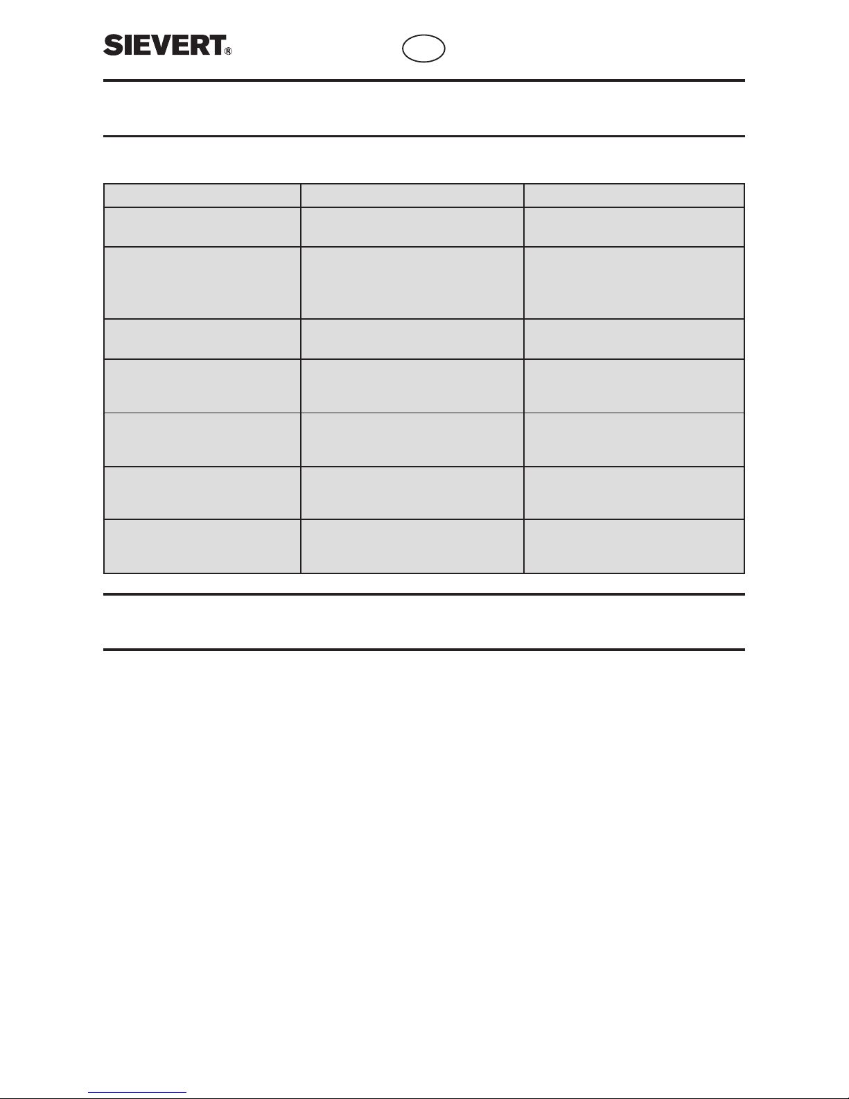
PROBLEM CAUSE CORRECTION
Will not start 1. No Power 1. Check the electric supply or the
fuses
The desired temperature is not
reached
1. The temperature is set to 0˚C/0˚F
2. Wrong heating element is used
3. Tube for heating element missing
4. Defective heating element
1. Set correct temperature
2. Change heating element
3. Replace tube
4. Insert a new heating element
The machine is not mowing 1. Defective cog belt
2. Defective drive engine
1. Replace cog belt
2. Contact service centre
The machine is not functioning.
Fan running, text on display:
“TEMPSENSOR FAILURE”
1. The temperature sensor is not
plugged in properly
2. Faulty temperature sensor
1. Plug in temperature sensor
correctly
2. Replace temperature sensor
The machine is not functioning.
Text on display:
“INPUT VOLTAGE < 180V”
1. Too low incoming voltage 1. Check power supply
The machine is not functioning.
Text on display:
“INPUT VOLTAGE > 450V”
1. Too high incoming voltage 1. Check power supply
The machine is not functioning.
Fan running, text on display:
“HIGH AMBIENT TEMPERATURE”
1. Fan unit overheated 1. Make sure that the air intake is
clean and not clogged
SERVICE AND REPAIR
All service and repair should be done only by an authorized Sievert Service Centre.
For a service centre near you, please see contact information on the backside or at www.sievert.se
GB
Page 11
ACCESSORIES & SPARE PARTS
- 11 -
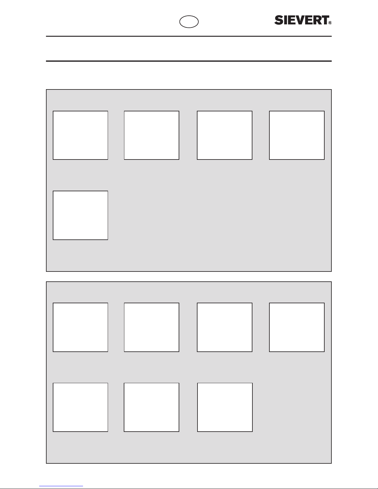
Only ofcial and approved Sievert accessories and spare parts shall be used.
ACCESSORIES
Art no. 299301
Additional weight 4 kg
Art no. 799070
Metal transport box
Art no. 799080
Cleaning brush with
brass wire
Art no. 799001
Replacement heating
element 400 V ~
Art no. 799047
Replacement heating
element 230 V ~
Art no. 799020
Drive belt
Art no. 799030
Nozzle 40 mm
Art no. 799040
Temperature sensor
Art no. 799050
Fan complete
Art no. 799060
Electronic display unit
Art no. 799090
Screw repair kit
SPARE PARTS
Art no. 799010
Welding belt
GB
Page 12
6
5
12
2
3
4
9
10
8
2
7
1
11
- 12 -
TW 5000 OVERVIEW
GB
3,00 m/min
550°C
*
*
13
14
15
16
17
18
20
19
21
23
24
25
22
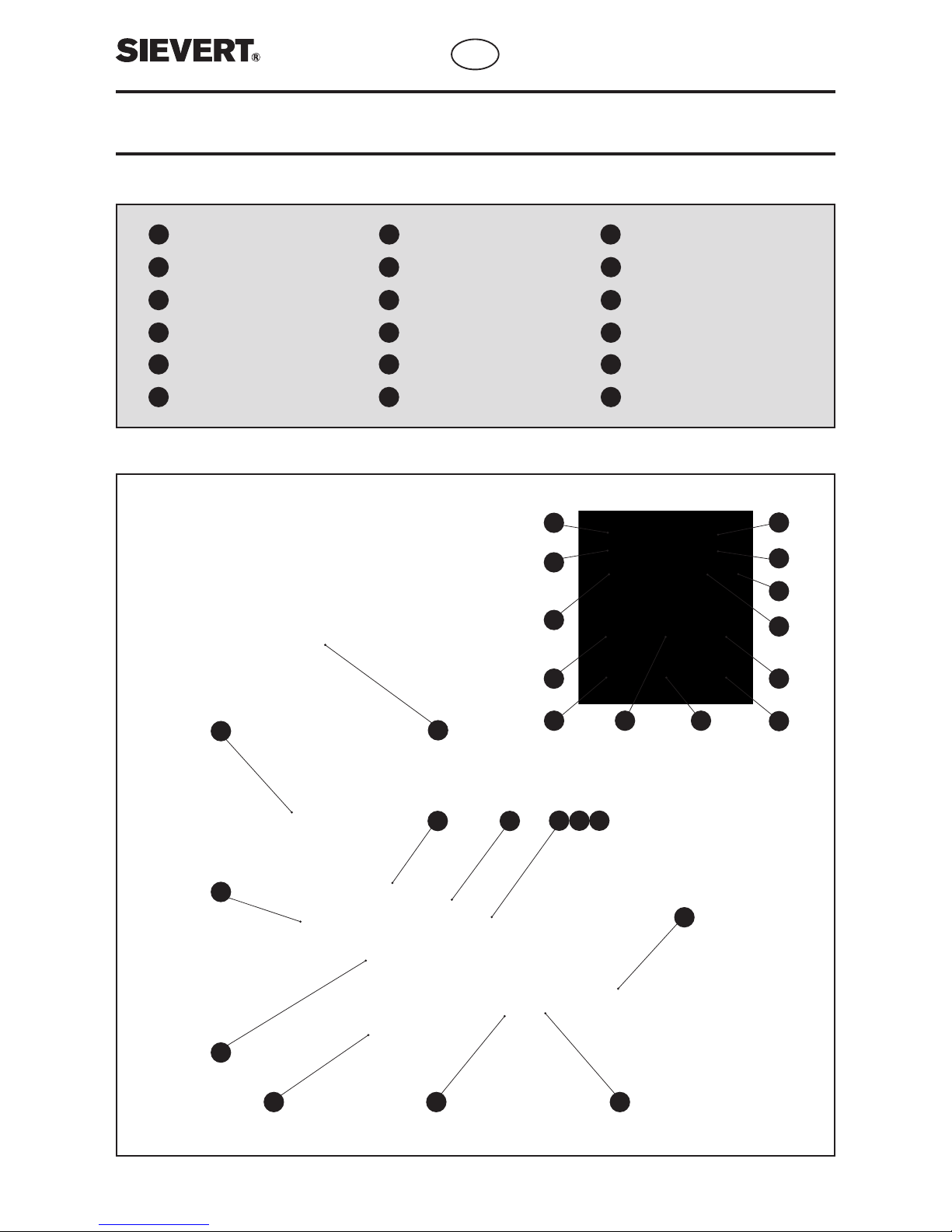
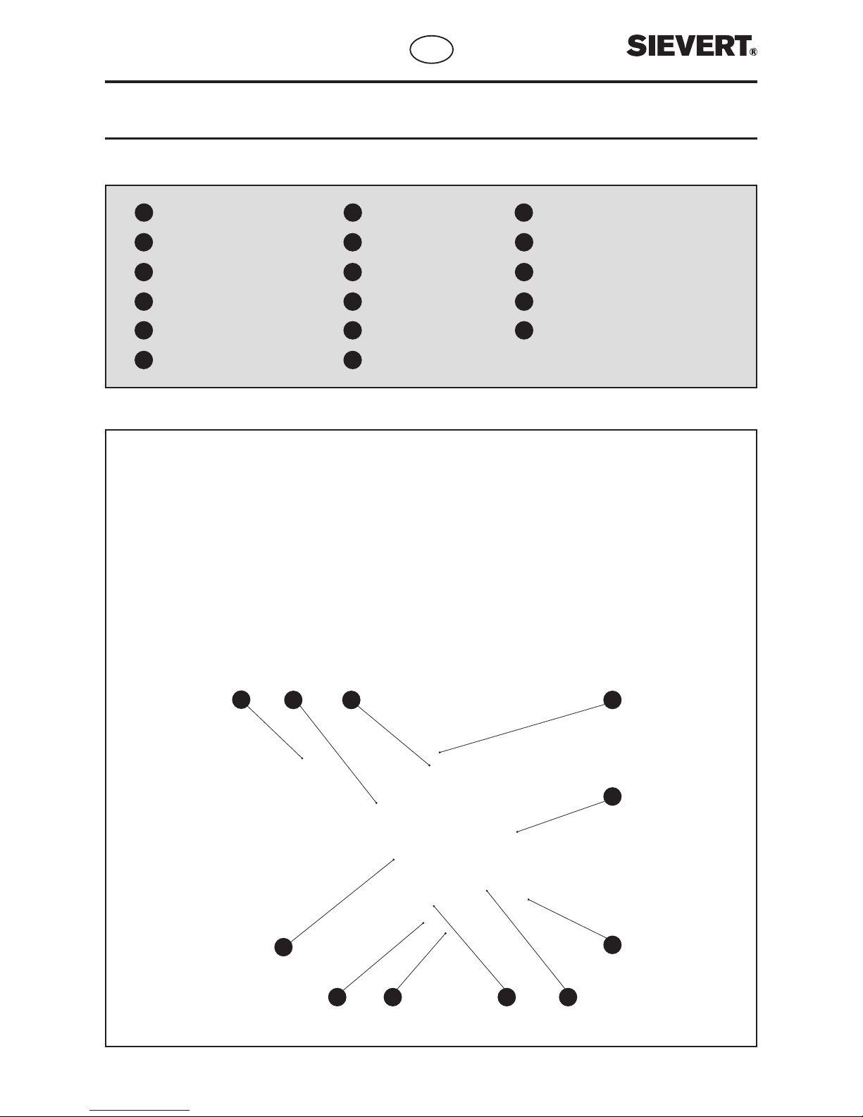
Adjustable handle
Cable hook
Handle adjustment knob
Nozzle heat shield
Welding nozzle
Tube for heating element
Heating element
Weight 8 kg / 17.6 lb
Pressure wheel
Silicone welding belt
Adjustable front wheels
Fan release trigger
1
2
3
4
5
6
7
8
9
10
11
12
13
14
15
16
17
18
°C/m or °F/f
Automatic start indicator
Drive indicator
Status “wait” indicator
Status “ready” indicator
Temp. adjustment knob
Page 13
Fan unit
Start button
Fan adjustment knob
Manually run button
Speed adjustment knob
Power indicator
Temperature indicator
Speed indicator
Lifting handle
Display unit
Lifting handle
Power cord
19
20
21
22
23
24
25
26
27
28
29
30
31
32
33
34
35
Transportation wheel
Front wheels adjustment knob
Guide wheel adjustment bolt
Guide wheel
Main switch on/off
29
28
27
26
31
34
33
35
31
32
30
- 13 -
TW 5000 OVERVIEW
GB
Page 14

- 62 -
NOTES
.....................................................................................................................................................
.....................................................................................................................................................
.....................................................................................................................................................
.....................................................................................................................................................
.....................................................................................................................................................
.....................................................................................................................................................
.....................................................................................................................................................
.....................................................................................................................................................
.....................................................................................................................................................
.....................................................................................................................................................
.....................................................................................................................................................
.....................................................................................................................................................
.....................................................................................................................................................
.....................................................................................................................................................
.....................................................................................................................................................
.....................................................................................................................................................
.....................................................................................................................................................
.....................................................................................................................................................
.....................................................................................................................................................
Page 15

- 63 -
NOTES
.....................................................................................................................................................
.....................................................................................................................................................
.....................................................................................................................................................
.....................................................................................................................................................
.....................................................................................................................................................
.....................................................................................................................................................
.....................................................................................................................................................
.....................................................................................................................................................
.....................................................................................................................................................
.....................................................................................................................................................
.....................................................................................................................................................
.....................................................................................................................................................
.....................................................................................................................................................
.....................................................................................................................................................
.....................................................................................................................................................
.....................................................................................................................................................
.....................................................................................................................................................
.....................................................................................................................................................
.....................................................................................................................................................
Page 16
51499 ©Sievert AB. All rights reserved. Sievert is a registered trademark of Sievert AB.
DESIGN AND QUALITY
SIEVERT AB SWEDEN SINCE 1882
www.sievert.se
Sievert Industries, Inc.
5255 Zenith Parkway
Loves Park, IL 61111
Ph: +1 815 639 1319
US
James Lister & Sons Ltd.
Sandwell Industrial Estate
Spon Lane South, Smethwick
West Midlands, B66 1QJ
Ph: +44 121 506 1818
Sievert AB
P.O Box 1366
SE-171 26 Solna
Ph: +46 8 629 22 00
Oy Primus Ab
PL 116
FIN-02201 Espoo
Ph: +358 9 525 9360
Primus AS
Postboks 58, Alnabru
NO-0614 Oslo 6
Ph: +47 23 384 320
Andersen & Nielsen København A/S
H.J Holst Vej 6
DK-2610 Rødovre
Ph: +45 364 102 00
Sievert GmbH
Ettore-Bugattistr. 43
Gewerbepark II
DE-51149 Köln/Porz
Ph: +49 2203 953 10
S.A Sievert
Antwerpsesteenweg 59
BE-2630 Aartselaar
Ph: +32 3 870 87 87
Sievert N.V
Antwerpsesteenweg 59
BE-2630 Aartselaar
Ph: +32 3 870 87 87
Intergros Handels AG
Alter Zürichweg 21
CH-8952 Schlieren
Ph: +41 175 577 77
Stag S.A
Poligono Industrial de Vallecas
C/ Luis I, Nave 6-A2
E-280 31 Madrid
Ph: +34 91 777 0866
Ferrutat Colimar SPA
Viale Monza 338
IT-20128 Milano
Ph: +39 0227 000 607
Petroprimus ZAO
Kantimirovkaja UL D.7
RU-194100 St. Petersburg
Ph: +7 812 327 4418
Rothenberger Hellas SA
249 Sigrou Avenue
GR-171 22 N. Smirni
Ph: +30 210 940 7302
Patimex Ots
NA Zizkove 523
CZ-364 52 Zlutice
Ph: +420 353 393 642
Rothenberger Polska SP.ZO.O
UL. Cyklamenow 1
PL-04-798 Warszawa
Ph: +48 22 612 77 01
S
D
F
N
DK
FIN
GB
I
E
CH
RU
CZ
PL
GR
NL
B
 Loading...