

Page 1
lssue date: July, 2012
NO.G11216570
ZEUS SERIES
SST-ZM1350
The benchmark of stability, flexibility, and power
1350W continuous output and 1500W peak power (at 50°C)
Six / Single +12V rails adjustable switch
Class-leading +12V rails combined loading up to 105A
O
Low ripple & noise with strict ±1% voltage regulation
User-accessible +3.3V / +5V / +12V rails voltage adjustment pots
80 PLUS Silver certification with 80 PLUS Gold level efficiency at 230Vac
Advanced 100% full cable management
Industrial grade components
Long life dual ball bearing 80mm fan with speed control switch
Page 2
1-3-1. Cold Start
ZEUS SERIES
SPECIFICATION
SilverStone ZEUS
ZM1350
ATX12VSwitching Power Supply
With Active PFC
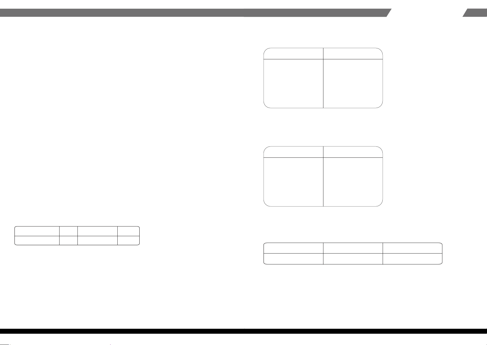
1. Input Requirements
1.1 Input Voltage
The power supply shall be operated at universal input voltage defined in the following
table.
Conditions Limits
115/230VAC, full load.
25℃ ambient.
1-3-2. Warm Start
Conditions Limits
Turn off at 132/264VAC
full load for 1 sec then
turn on at the peak
of the input voltage
cycle at 25℃ ambient.
No component over
stress or damage
should occur to the
power supply.
Input fuse shall
not blow.
No component over
stress or damage
should occur to the
power supply.
Input fuse shall
not blow.
Table 1 AC Input Line Requirements
lnput Voltage
Voltage
Power factor correction (PF)>0.90 at full load.
1.2 Frequency
The input frequency range is from 50Hz to 60Hz.
1-3. Inrush Current
The max inrush current is 160A for 230VAC 90A for 115VAC.
01
Min
90
Nom.
100 - 240
Max
264
1-4. AC Input Current
AC Input MAX
18-9
1-5. Efficiency
The power supply efficiency shall not be less than85% at the maximum
load of sec. 2.2 and 115Vac input voltage.
Units
AMPS100-240V
02
Page 3
ZEUS SERIES
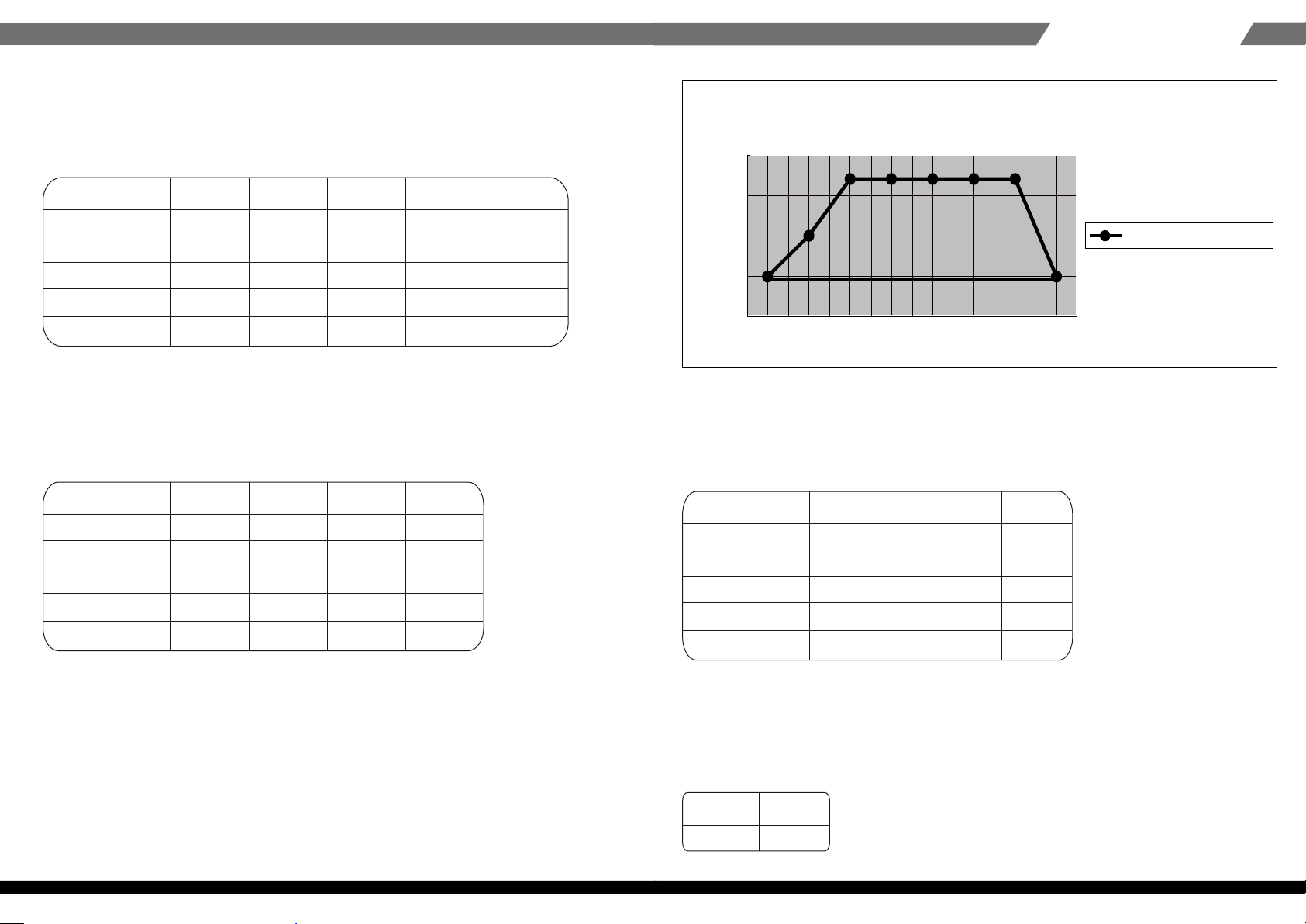
1350W C ross Regulation
(5 V rail + 3 .3 V v s . 1 2 V )
0
50
100
150
200
150 300 450 600 750 900 1050 1200
12V pow er (w atts)
5V+3.3V power (watts)
2. Output Requirements
2-1. Output Regulations
The power supply shall be operated at universal input voltage defined in the following
table.
Output Voltage Range
+5V 1%
+12V1~V6
-12V
+3.3V
+5Vsb
Note: 1). The above voltage range should also include ripple and noise.
2). The output voltage should be measured at the terminals of output connector.
+
-
+
1%
-
+
10%
-
+
1%
-
+
5%
-
2-2. DC Load Requirements
Output Voltage
MIN NOM MAX Units
+5V 1.0
+12V1~V6 15 30 AMPS
-12V 0.25 0.5 AMPS
+3.3V 12.5 25 AMPS
+5Vsb 2 4 AMPS
1.0
0.0
1.0
0.1
MIN Nominal MAX Units
+4.95 +5.00 +5.05 Volts
+11.88 +12.00 +12.12 Volts
-10.80 -12.00 -13.20 Volts
+3.26 +3.30 +3.33 Volts
+4.75 +5.00 +5.25 Volts
12.5 25 AMPS
2-4. +5V standby voltage
The +5Vsb is on whenever the AC power is present.
2-5. DC Output Voltage Ripple and Noise
Output Voltage
Ripple & Noise Max U
+5V 20
+12V1~V6 mV
-12V mV
+3.3V mV
+5Vsb mV
25
120
20
50
Operation : nits
mV
3.3V&+5V power (watts)
Note : 1). The maximum continuous total DC output power shall not exceed1350 Watts.
2). The maximum continuous combined load on +5V and +3.3V outputs shall not exceed 170 Watts.
3). The maximum continuous combined load on +12V1outputs shall not exceed 1260 Watts.
4). The maximum continuous combined load on +5V, +3.3V and +12V1~+12V6 outputs shall
not exceed 1324Watts.
2-3. Cross Regulation
The DC loads shall remain within the ranges specified in 2-2 DC Load Requirements
and the DC output voltages also shall remain within the regulation ranges specified
in 2-1 Output Regulation when measured at the load end of the output connectors.
03
Note : 1)The measurements should be made by crossing a 10uF/ electrolytic and a 0.1uF ceramic disk
capacitors at each output with measuring bandwidth from DC to 20 MHz. If ambient temperature
is under 20℃ or over 30℃, the AC input should be nominal input.
2-5. DC Output Voltage Ripple and Noise
MAX
1350
Units
Watts
04
Page 4

ZEUS SERIES
2-7. Remote ON/OFF Control
The power supply outputs shall be enabled with an active-low TTL signal.
When TTL signal is low, the DC outputs are to be enabled.
When TTL signal is high or open circuited, the DC outputs are to be disabled.
Electronic means or a mechanical switch may activate the TTL signal.
After the TTL signal is active high, must wait for 3 seconds before active low again.
2-8. Power Sequence
2-11. Power Good Delay Time (T3)
MIN
100
The test environment is 25℃ condition @ nominal input.
MAX
500
Units
ms
2-12. Power Good Rise Time (T4)
MAX
10
Units
ms
2-13. Hold Up Time (T5)
MIN
16
The test environment is 25℃ & full load condition @ nominal input.
Units
ms
2-14. Power Fail Signal (T6)
Power good signal shall go to a down level 1ms before +5V output voltage falls
below the regulation limits during PS-ON signal pull high.
2-9. Power On Time (T1)
MAX
1000
Units
ms
2-10. Rise Time (T2)
MIN
1.0
05
MAX
50
Units
ms
MIN
1.0
Units
ms
3. Protections
3-1. Over Voltage Protection
When the DC outputs (+5V, +12V1~+12V6, +3.3V) have over voltage condition,
the power supply shall provide latch mode over voltage protection.
06
Page 5

ZEUS SERIES
DC output
+12V1~+12V6 15.5
+5V V
+3.3V V
3-2. Short Circuit Protection
A short circuit placed to ground shall cause no damage or power supply
shall be shutdown. (The contact resistance is 0.05 ohm when the outputs short circuit.)
3-3. Protection Reset
When the power supply latches into shutdown condition due to a fault
on an+5V,+3.3V,+12V1~+12V6 output( OVP, UVP), the protection
shall reset after the fault has been removed, use remote on/off control
or recycle the AC power again for a typical of 5 seconds.
3-4. Over Shoot
Any output overshoot at turn on shall be less than 15% of the nominal
output value (with resistive load) as described in sec. 2.1.
3-5. Over Power Protection
At 115/230Vac input the power supply will shut down all DC output
within 110% to 150% of full load.
Max Units
V
6.5
4.6
4-2. Humidity (none condensing)
TOperation: 20% to 85% RH (nominal input)
Storage : 10% to 95% RH
5. Safety
5-1. UL60950-1,
5-2. TUV EN 60950-1
6. EMI Requirements
6-1.CE
6-2.BSMI
6-3.FCC part 15 sub part J class B at system load
6-4.CISPR 22 CLASS B
7. Dielectric Voltage Withstand (HI-POT)
The power supply shall withstand for 3 seconds without breakdown the application
of an 1800Vac-supply voltage applied between both input line and chassis
(15mA AC Cutoff current).
Isolating transformers shall similarly withstand 4242Vdc applied between both primary
and secondary windings for a minimum of one minute.
4. Environment
4-1. Operation/Storage Temperature Range
Operation : 5℃ to 50℃ (nominal input)
Storage : -40℃ to 70℃
07
LOAD
100%
80%
8. PFC
Active Power Factor Correction, complies with
EN 61000-3-2: 1995+A1+A2:1998, Class D.
9. Electrostatic Discharge (ESD)
Comply with IEC 61000-4-2.
10. EFT/ Burst
60℃ 50℃
Comply with IEC 61000-4-4.
08
Page 6

ZEUS SERIES
11. Surge
Comply with IEC 61000-4-5.
12. Burn-In
Applying 115 Vac 10 % or 230 Vac 10% input voltage and maximum
load for this product in 40 5 ℃ chamber.
+
-
+
-
+
-
13. M.T.B.F.
The power supply shall have a minimum mean time between failure greater than
100,000 hours at continuous operation of 100% load and an ambient temperature
of 25℃ .
14. Dimension.
230(D)X 150(W)X 85(H) mm.
15. Connectors.
M/B 24PIN connector
EPS 12V 8PIN connector
Signal Pin Pin Signal
Yellow +12V 5 1 COM Black
Yellow
Yellow
Yellow
+12V 6 2 COM Black
+12V 7 3 COM Black
+12V 8 4 COM Black
ATX 12V 4PIN (4+4PIN EPS 12V in split mode)
Signal Pin Pin Signal
Black GND 1 3 +12V Yellow
Black GND 2 4 +12V Yellow
4PIN peripheral connector (HDD) 4PIN floppy connector (FDD)
Signal Pin Pin Signal
Yellow
+12V 1
Black COM 2 2 COM Black
Black COM 3 3 COM Black
Red +5VDC 4 4 +12V Yellow
1 +5VDC Red
09
SATA connector
Signal Pin
Orange
Black
Red
Black
Yellow
+3.3V 5
COM 4
+5V 3
COM 2
+12V 1
10
Page 7

ZEUS SERIES
6PIN PCI Express connector
Signal Pin Pin Signal
Yellow
Yellow
Yellow
+12V 1 4 COM Black
+12V 2 5 COM Black
+12V 3 6 COM Black
16. Special function
NOTE:Six / Single +12V rails switch
This switch should only be used when the power supply is turned off via its own power
switch or with the power cord unplugged. Please do not adjust the switch when the PSU
is in operation.
NOTE:Voltage adjustment pots
Please fine tune the +12V, +5V, +3.3V adjustment pots gradually while monitoring the
changes via system monitor (BIOS, digital readabout, software, etc…)
Warranty Information
This product has a limited 5 year warranty in North America, Europe, and Australia.
For information on warranty periods in other regions, please contact your reseller or SilverStone authorized distributor.
Warranty terms & conditions
1. Product component defects or damages resulted from defective production is covered under warranty.
Defects or damages with the following conditions will be fixed or replaced under SilverStone Technology’s jurisdiction.
a) Usage in accordance with instructions provided in this manual, with no misuse, overuse, or other inappropriate actions.
b) Damage not caused by natural disaster (thunder, fire, earthquake, flood, salt, wind, insect, animals, etc…)
c) Product is not disassembled, modified, or fixed. Components not disassembled or replaced.
d) Warranty mark/stickers are not removed or broken.
Loss or damages resulted from conditions other than ones listed above are not covered under warranty.
2. Under warranty, SilverStone Technology’s maximum liability is limited to the current market value for the product (depreciated value, excluding
shipping, handling, and other fees). SilverStone Technology is not responsible for other damages or loss associated with the use of product.
3. Under warranty, SilverStone Technology is obligated to repair or replace its defective products. Under no circumstances will SilverStone
Technology be liable for damages in connection with the sale, purchase, or use including but not limited to loss of data, loss of business, loss of
profits, loss of use of the product or incidental or consequential damage whether or not foreseeable and whether or not based on breach of warranty,
contract or negligence, even if SilverStone Technology has been advised of the possibility of such damages.
4. Warranty covers only the original purchaser through authorized SilverStone distributors and resellers and is not transferable to a second hand
purchaser.
5. You must provide sales receipt or invoice with clear indication of purchase date to determine warranty eligibility.
6. If a problem develops during the warranty period, please contact your retailer/reseller/SilverStone authorized distributors or SilverStone
http://www.silverstonetek.com.
Please note that: (i) You must provide proof of original purchase of the product by a dated itemized receipt; (ii) You shall bear the cost of shipping
(or otherwise transporting) the product to SilverStone authorized distributors. SilverStone authorized distributors will bear the cost of shipping
(or otherwise transporting) the product back to you after completing the warranty service; (iii) Before you send the product, you must be issued a
Return Merchandise Authorization (“RMA”) number from SilverStone. Updated warranty information will be posted on SilverStone’s official website.
Please visit http://www.silverstonetek.com for the latest updates.
Additional info & contacts
For North America (usasupport@silverstonetek.com)
SilverStone T echnology in North America may repair or replace defective product with refurbished product that is not new but has been functionally tested.
Replacement product will be warranted for remainder of the warranty period or thirty days, whichever is longer. All power supplies should be sent
back to the place of purchase if it is within 30 days of purchase, after 30 days, customers need to initiate RMA procedure with SilverStone Technology
in USA by first downloading the “USA RMA form for end-users” form from the below link and follow its instructions.
http://silverstonetek.com/contactus.php
For Australia only (support@silverstonetek.com)
Our goods come with guarantees that cannot be excluded under the Australian Consumer Law.
You are entitled to a replacement or refund for a major failure and for compensation for any other reasonably foreseeable loss or damage.
You are also entitled to have the goods repaired or replaced if the goods fail to be of acceptable quality and the failure does not amount to a major failure.
Please refer to above “Warranty terms & conditions” for further warranty details.
SilverStone Technology Co., Ltd. 12F No. 168 Jiankang Rd., Zhonghe Dist., New Taipei City 235 Taiwan R.O.C. + 886-2-8228-1238
(standard international call charges apply)
For Europe (support.eu@silverstonetek.de)
For all other regions (support@silverstonetek.com)
11
12
 Loading...