

Page 1
January, 2013
TJ04-E
Reinterpretation of an all-time classic
NO: G11214911
Page 2
Installation and system optimization guide:
The following manual and guides were carefully prepared by the SilverStone engineering
team to help
Please keep this manual for future reference when upgrading or performing maintenance
on your system. A copy of this manual can also be downloaded from our website at:
http://www.silverstonetek.com
you maximize the potential of your SilverStone product.
TJ04-E
Contents
Specifications
Disassemble Chart
Installation guide
Front panel connector guide
Front I/O connector guide
Component size limitations
Recommended cooling device setup and selection
Cable routing
Upgrade and maintenance
Q & A
P.2
P.3
P.5
P.18
P.20
P.21
P.29
P.31
P.35
P.41
1
Page 3
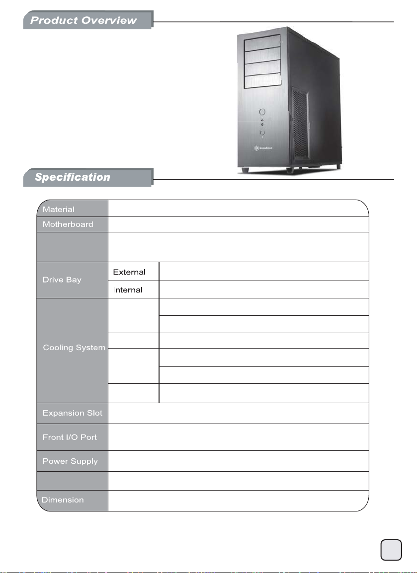
Temjin series
TJ04-E
Reinterpretation of an all-time classic
Aluminum front panel, steel body
SSI CEB, ATX (up to 12" x 10.9"), Micro ATX
Model No.
SST-TJ04B-E (Black)
SST-TJ04B-EW (Black + Window)
5.25" x 4
3.5" x 9 (optional 3.5" x 8 + 2.5" x 1), 2.5" x 6
Right
Rear 1 x 120mm exhaust fan, 1200rpm, 21dBA
Top
Bottom 1 x 120mm fan slot (optional)
USB 3.0 x 2 (backwards compatible with USB 2.0)
audio x 1 / MIC x 1
1 x optional standard PS2 (ATX)*
Expansion Card
*1 – If bottom fan or 2.5” SSD is installed, the maximum depth for PSU is 180mm (or 160mm
with extra cabling room), otherwise there are no depth limitations.
*2 – If hard drive is installed in front of the cards, the length limitation is 12.8 inches.
Compatible up to 17 inches in length*
214mm(W) x 489mm(H) x 489mm(D)
1 x 120mm intake fan, 1200rpm, 21dBA
1 x 120mm fan slot (optional)
1 x 120mm intake fan, 1200rpm, 21dBA
1 x 120mm or 140mm fan slot (optional)
8
1
2
2
Page 4
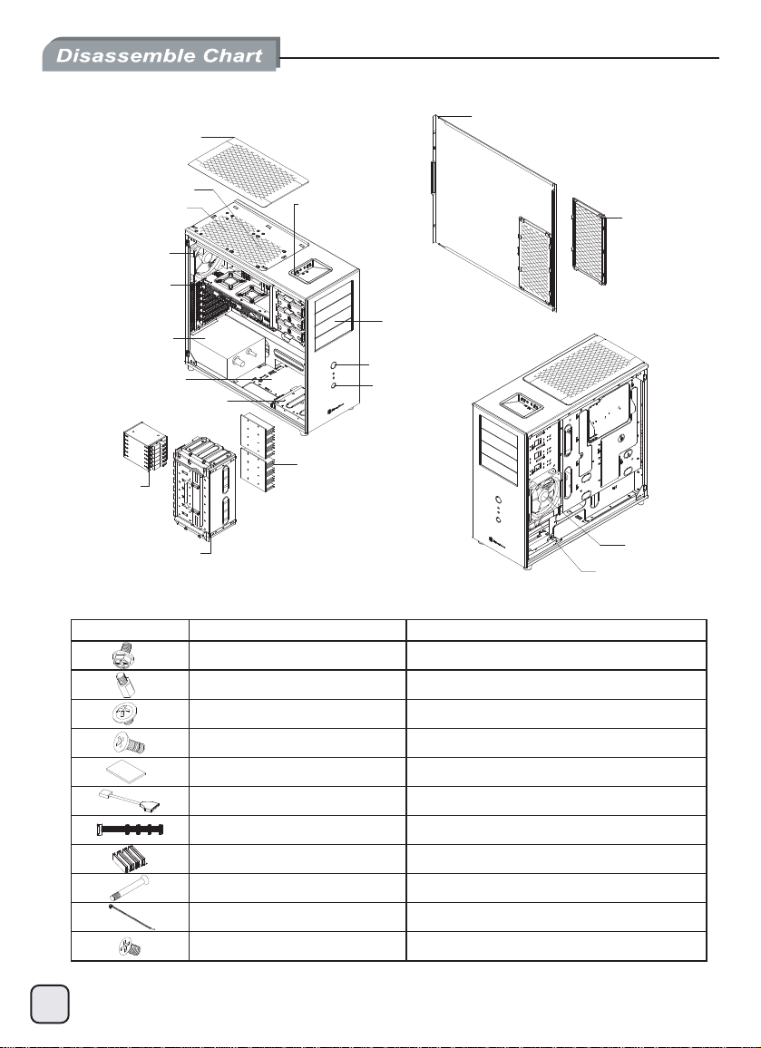
TOP FILTER
RIGHT SIDE PANEL
12025 FAN x 1
12025 FAN x 1(OPTION)
12025 FAN x 1
EXPANSION SLOTS x 8
PS2 PSU(OPTION)
12025 FAN x 1(OPTION)
3.5” OR 2.5” DRIVE BAY x 1
2.5” DRIVE BAY x 6
3.5” DRIVE BAY x 8
TOP I/O
USB 3.0 x 2
SPK x 1
MIC x 1
5.25” DRIVE BAY x 4
POWER BUTTON
RESET BUTTON
HDD HEAT SINK x 2
METIERUTCIP
UP
ESOPR
RIGHT SIDE
FILTER
12025 FAN x 1
12025 FAN x 1(OPTION)
SCREW-H/W-6-32*6-NI SECURE PSU,MB,HDD,HDD HEATSINK
STANDOFF-6-32*6.5H-6-32 SUPPORT MB
SCREW-P/W-M3*6-NI SECURE CD-ROM
SCREW-T/F-6-32*6-NI SECURE 3.5 HDD ON THE BOTTOM
MANUAL USER INSTALLATION GUIDE
USB CABLE USB3.0 CONVERT TO USB 2.0
SATA-POWER-CABLE HDD POWER CABLE CHAIN
HDD-HEAT-SINK HDD COOLER
SCREW-T/F-M3*27-NI SECURE 12025 FAN
BUNCH WIRE TIES CABLE MANAGEMENT
SCREW-T/F-M3*4-NI SECURE 2.5 HDD
3
Page 5
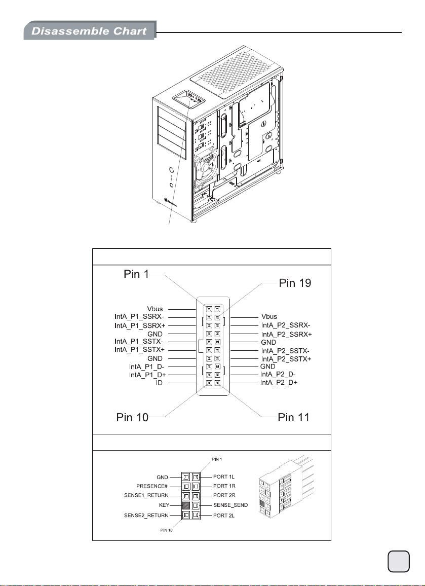
FRONT I/O ( USB 3.0 x 2 / audio x 1 / MIC x 1 )
USB 3.0 CONNETOR
HD AUDIO CONNETOR
4
Page 6
lnstallation Guide
Before you begin, please make sure that you
(1) have all components collected.
(2) check that all components do not have compatibility problems with each other or with the case.
!
Caution
(3) if possible, assemble the components outside the case first to make sure they are working.
(4) keep the motherboard manual ready for reference during installation.
(5) prepare a Philips screwdriver.
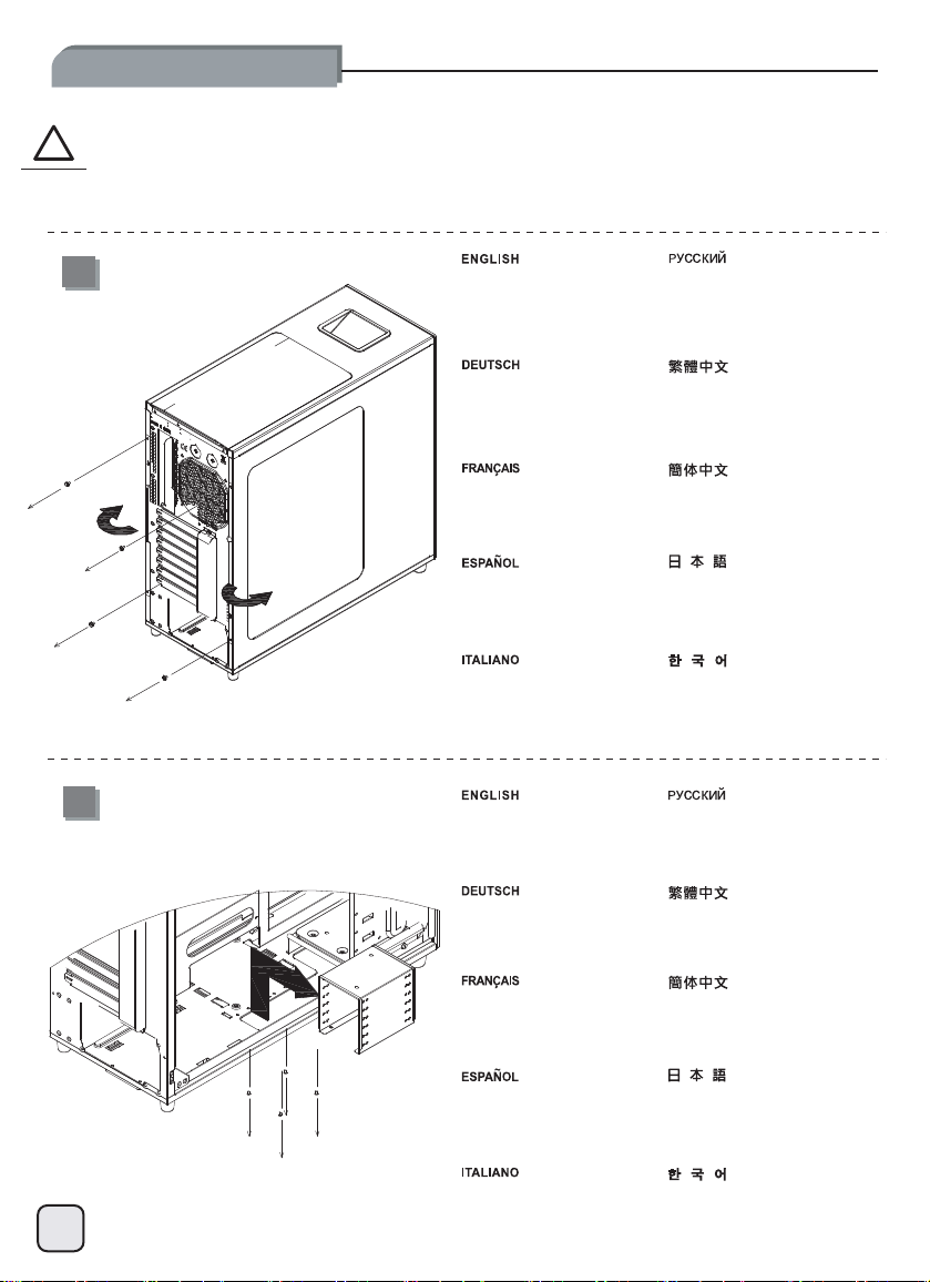
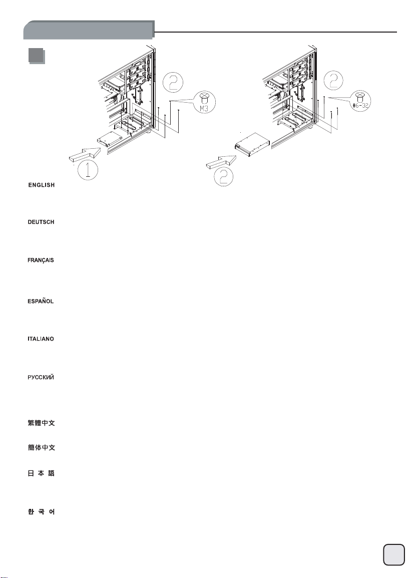
1
2
Loosen screws from both side
panels to remove them.
Lösen Sie die Schrauben der
beiden Seitenwände um diese
abzunehmen.
Dévissez les vis des deux
panneaux latéraux afin de les
retirer.
Afloje los tornillos de ambos
paneles laterales para retirarlos.
Allentare le viti di entrambi i
pannelli per rimuoverli.
Remove 2.5” hard drive cage.
Entfernen Sie den
2,5“-Festplattenkäfig.
Отверните винты
боковых
移除左右側板螺絲,
取下側板。
移除左右侧板螺丝,
取下侧板。
両方の側面パネルのネジをゆるめ
て取り外します。
나사를 분리하려면 양쪽
패널에서 나사를 푸십시오.
Извлеките корпус
2,5-
дюймового жесткого диска.
移除2.5”硬碟架。
обеих
панелей и снимите
их.
Retirez la cage pour lecteur de
disque dur 2,5 pouces.
Quite la carcasa para discos
duros de 2,5”.
Rimuovere il supporto degli hard
disk da 2,5”
移除2.5”硬盘架。
2.5”ハードドライブケージを取
り外します。
2.5”하드 드라이브 케이스를
분리하십시오.
5
Page 7
lnstallation Guide
Place the power supply into the
3
chassis, if the power supply has
120mm or greater fan built-in, we
recommend installing with the fan
facing down.
Platzieren Sie das Netzteil im
Gehäuse. Falls das das Netzteil
einen Lüfter mit einer Größe von
120 mm oder mehr aufweist,
empfehlen wir eine Netzteilinstallation mit nach unten zeigendem
Lüfter.
Placez le bloc d’alimentation dans
le châssis ; si ce bloc est doté
d’un ventilateur de 120mm ou
davantage, nous vous conseillons
de l’installer ventilateur tourné
vers le bas.
Ponga la fuente de alimentación
en el chasis, si la fuente de
alimentación tiene un ventilador
incluido de 120mm ó más, le
recomendamos que la instale con
el ventilador hacia abajo.
Disporre l’alimentatore nel case,
se la PSU ha una ventola da
120mm o più grande, vi
raccomandiamo di installarlo con
la ventola rivolta verso il basso.
Установите блок питания в
корпус.
Если в блоке питания
установлен
более, мы рекомендуем
устанавливать его вентилятором
вниз.
將電源供應器由上放入機殼內,
如果電源風扇尺寸在120mm及以上
建議將風扇面朝下安裝。
将电源供应器由上放入机箱内,
如果电源风扇尺寸在120mm及以上
建议将风扇面朝下安装。
電源をケースに入れます。電源が
120mm以上のファンを内蔵してい
る場合、ファンを下向きに取り付
けるようお勧めします。
전원 공급장치를 새시에
위치시키고 전원 공급장치에
120mm 이상의 내장형 팬이 있는
경우, 팬을 아래로 향하게 한
상태에서 설치하는 것이
좋습니다.
вентилятор 120 мм и
4
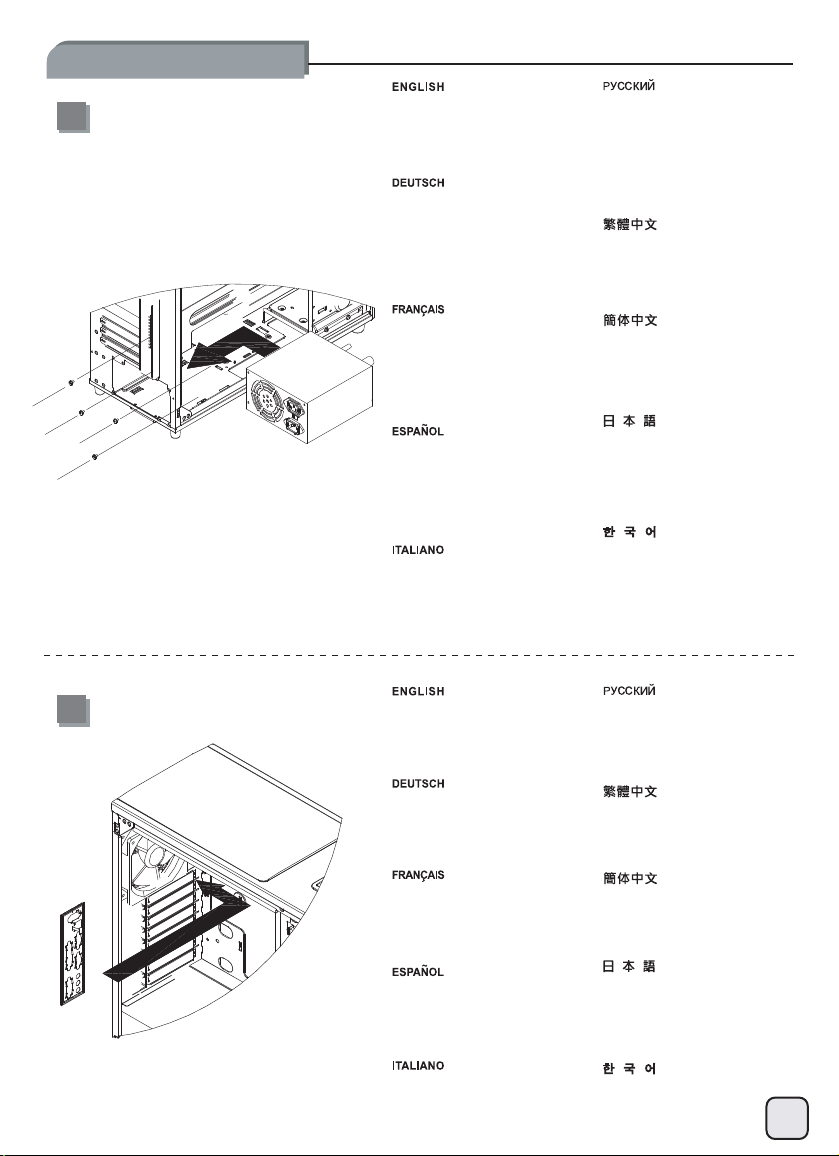
Install motherboard I/O shield into
the chassis.
Installieren Sie die I/O-Blende
des Mainboards im Gehäuse.
Installez le blindage E/S de la
carte mère dans le châssis.
Instale el escudo de E/S de la
placa base en el chasis.
Installare il pannellino I/O della
scheda madre nel case.
Установите в корпус планку
ввода/вывода системной
將I/O檔片裝上機殼。
将I/O檔片装上机箱。
ケースにマザーボードI/Oシール
ドを取り付けます。
메인보드 I/O 쉴드를 새시에
설치하십시오.
платы.
6
Page 8
lnstallation Guide
5
Install screw D standoffs onto the
motherboard tray as required,
then install motherboard into the
chassis and secure it with screw
C.
Installieren Sie die Abstandshalter
(Schrauben D) auf dem
Mainboard-Schlitten wie benötigt,
befestigen Sie dann das
Mainboard im Gehäuse mit den
Schrauben C.
Установите переходные стойки
D в соответствующие места
крепления системной платы,
затем установите системную
плату и закрепите ее винтами
C.
請依需求將SCREW D的主機板螺柱
鎖固於機殼,再將主機板裝入機殼
以SCREW C螺絲將其鎖固。
Fixez les douilles-entretoises des
vis D sur le plateau de la carte
mère tel que requis, puis insérez
la carte mère dans le châssis et
verrouillez-la en place à l'aide des
vis C.
Instale los soportes con el tornillo
D en la bandeja de la placa base
según sea necesario, luego
instale la placa base en el chasis
y fíjela con el tornillo C.
Installare gli standoffs (viti D) sul
supporto scheda madre secondo
necessità, quindi posizionare la
motherboard nel case ed
assicurarla alla struttura con le viti
C.
We recommend to start cable
routing at this point and connect
6
Vi raccomandiamo, a questo
punto, di iniziare con la
sistemazione dei cavi; collegate
quindi, ad esempio, il connettore
ATX 24pin e le varie connessioni
frontali.
7
all required connectors such as
the ATX 24pin, front panel
controller, or front I/O port
connectors.
Wir empfehlen, an diesem Punkt
mit dem Kabelmanagement zu
beginnen und alle benötigten
Kabel wie 24-Pin-ATX oder die
Kabelstränge der FrontpanelSteuerung und Front-I/OAnschlüsse zu verbinden.
Il est conseillé de débuter le
routage des câbles à ce stade et
de procéder au branchement des
divers connecteurs requis, tel que
le connecteur ATX 24 broches, le
contrôleur du panneau avant ou
les connecteurs des ports E/S
frontaux.
Le recomendamos que empiece
a enrutar los cables en este
momento y enchufe todos los
conectores necesarios, como el
ATX de 24 pines, el controlador
del panel frontal ó los conectores
de los puertos frontales de E/S.
请依需求将SCREW D的主机板螺柱
锁固于机箱,再将主机板装入机箱
以SCREW C螺丝将其锁固。
必要に応じてスペーサーのネジD
をマザーボードトレイ上にインス
トールしてから、ケースにマザー
ボードを取り付け、ネジCで固定
します。
필요할 경우 나사 D 스탠드오프를
메인보드 트레이에
메인보드를
C를 사용하여 이를
고정시키십시오.
На этом этапе мы рекомендуем
прокладку кабелей
начать
выполнить
подключения разъемов,
как
ATX 24pin, контроллер
передней
фронтальных портов
вывода.
我們建議您可以在此時開始理線,
並將ATX24Pin接線、Front panel
controller與Front I/O接頭安裝
完畢。
我们建议您可以在此时开始理线,
并将ATX24Pin接线、Front panel
controller与Front I/O接头安装
完毕。
この時点でケーブル取り回しを考
え、ATX 24ピン、フロントパネル
コントローラまたはフロントI/O
ポートコネクタといった全てのコ
ネクタを接続しておくようお勧め
します。
이 지점에서 케이블 연결 작업을
시작하고 ATX 24핀, 전면 패널
컨트롤러 또는 전면 I/O 포트
커넥터와 같은 필요한 모든
커넥터를 연결하는 것이
좋습니다.
설치한 다음,
새시에 설치하고 나사
необходимые
все
панели или разъемы
и
таких
ввода\
Page 9
lnstallation Guide
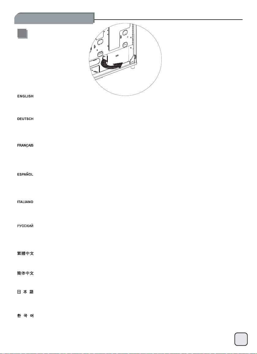
7
Route all power supply cables through the opening on the right side, then bundle and tie down excess cables for storage in the extra
space on the right side of the power supply. If power supply has modular cables, you may remove unused cables now.
Leiten Sie alle Netzteilkabel durch die Öffnung auf der rechten Seite, bündeln Sie diese und binden Sie alle überschüssigen Kabel
zusammen um sie im Freiraum auf der rechten Seite des Netzteils abzulegen. Falls das Netzteil modulare Kabel besitzt, können Sie
unbenutzte Kabel entfernen.
Faites passer tous les câbles d’alimentation à travers l’orifice situé du côté droit, puis regroupez-les et fixez l’excédant dans l'espace de
rangement situé à la droite du bloc d'alimentation. Si le bloc d’alimentation est doté de câbles modulaires, vous pouvez retirer l’excédant à
ce stade.
Enrute todos los cables de la fuente de alimentación a través de la abertura en el lado derecho, luego agrupe y ate los cables que sobren
para almacenarlos en el espacio extra en el lado derecho de la fuente de alimentación. Si la fuente de alimentación tiene cables
modulares, puede retirar ahora los cables que no vaya a usar.
Far passare tutti i cavi dell’alimentatore attraverso l’apertura posta a destra, quindi raccogliere ed unire insieme i collegamenti in eccesso
e disporli nello spazio presente alla destra dell’alimentatore.
Протяните
размещения в
кабель,неиспользуемый
請將所有電源線穿過電源右邊的開孔,將不需要用到的線材綁在電源右邊空間;若您使用模組化電源,請移除多餘線材。
请将所有电源线穿过电源右边的开孔,将不需要用到的线材绑在电源右边空间;若您使用模块化电源,请移除多余线材。
全ての電源ケーブルを右側の開口部に通し、電源右の余分のスペースに束ねて収めます。モジュラーケーブル装備の電源の場合は、未使
用のケーブルを取り外してください。
오른쪽 개구부를 통해 모든 전원 공급장치 케이블을 연결한 다음, 전원 공급장치 오른쪽 여백에 보관하기 위해 과도한 케이블을
다발로 만들어 묶으십시오. 전원 공급장치에 모듈 방식의 케이블이 있는 경우, 사용되지 않은 케이블을 현재 분리할 수 있습니다.
все кабели питания
свободном пространстве
кабель
отверстиенаправой
через
с правой стороныотблока
можно
убрать.
, затем сверните
стороне
питания. Если в боке питания используется модульный
излишки
кабелей в
жгут и свяжите их
для
8
Page 10
lnstallation Guide
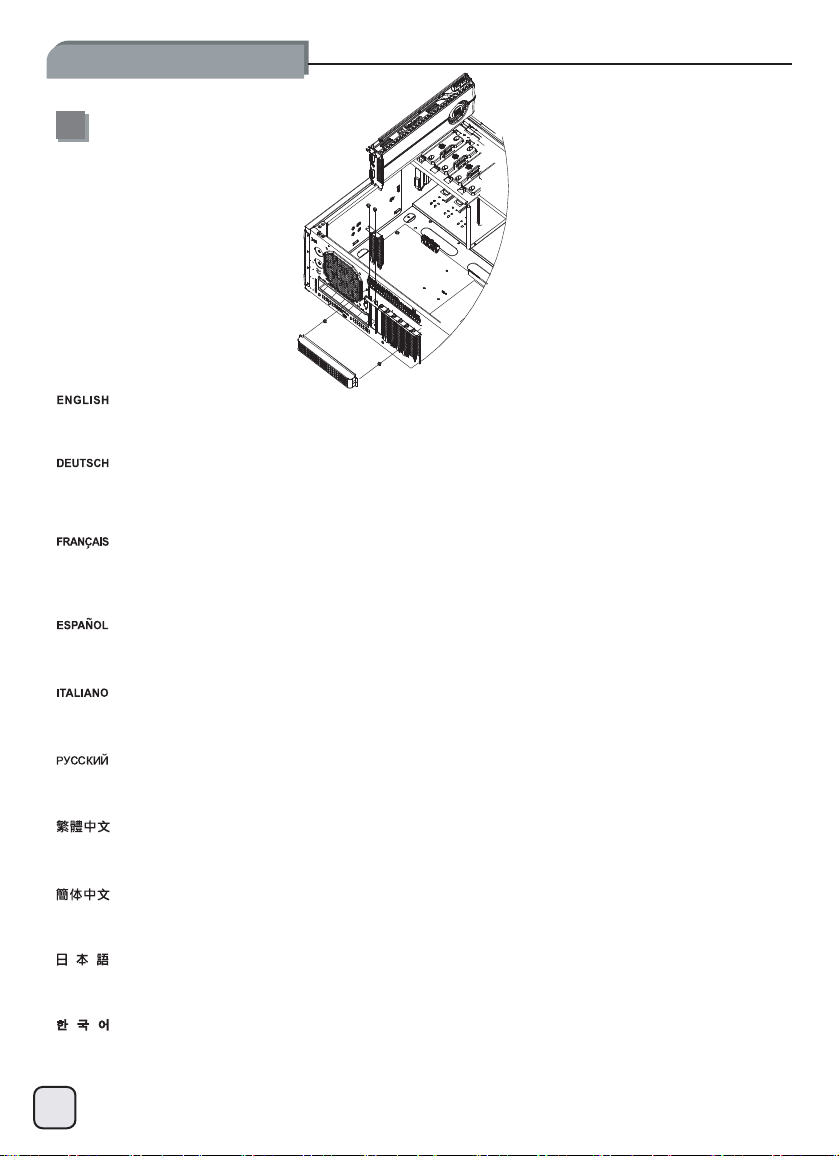
8
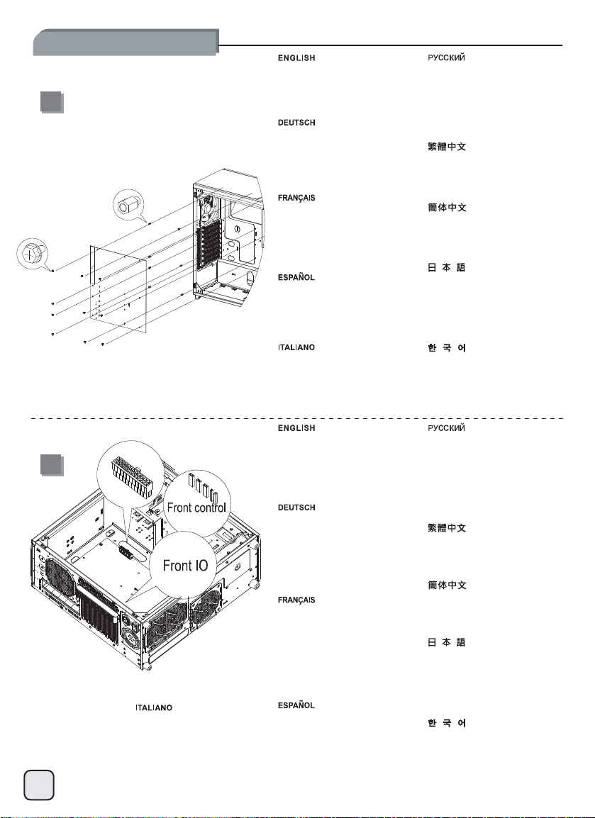
Remove expansion slot covers, then install required expansion cards and secure with included screws.
Entfernen Sie die Blenden der Erweiterungssteckplätze, installieren Sie dann benötigte Erweiterungskarten und befestigen Sie diese mit
den beigelegten Schrauben.
Retirez les caches des fentes d’expansion, puis installez les cartes d’expansion requises et verrouillez-les en place à l’aide des vis
fournies.
Retire las cubiertas de los zócalos de expansión, luego instale las tarjetas de expansión necesarias y fíjelas con los tornillos incluidos.
Rimuovere i cover degli slot di espansione, quindi installare le schede necessarie ed assicurarle alla struttura del case con l
Снимите
заглушки слотов расширения, установите нужные карты расширения и закрепите их в
取下擴充槽上的檔板,安裝擴充卡並以內附螺絲鎖固。
取下扩充槽上的档板,安装扩充卡并以内附螺丝锁固。
拡張スロットカバーを取り外してから、必要な拡張カードを取り付け、付属のネジで固定します。
확장 슬롯 커버를 분리한 다음, 필요한 확장 카드를 설치하고 제공된 나사를 사용하여 고정시키십시오.
гнездах
винтами из комплекта.
9
e viti incluse.
Page 11
lnstallation Guide
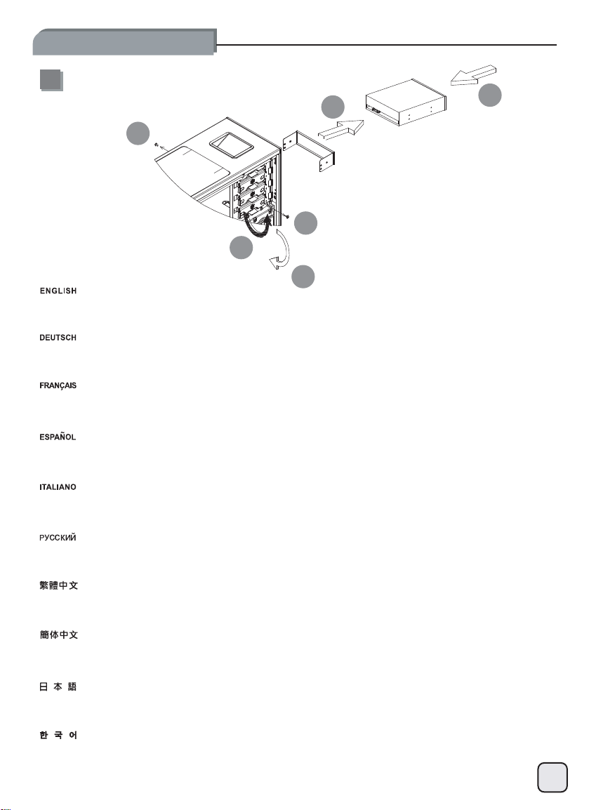
9
2
1
1
3
5
Remove 5.25” drive bay covers then install 5.25” devices as required.
Entfernen Sie die Blenden der 5,25“-Laufwerksschächte und installieren Sie benötigte 5,25“-Geräte.
Retirez les caches des baies pour lecteur 5,25 pouces et installez un ou plusieurs lecteurs 5,25 pouces selon vos besoins.
Retire las cubiertas de las bahías de dispositivos de 5,25” y luego instale los dispositivos de 5,25” que precise.
4
Rimuovere i cover dei bay da 5,25” ed installare le periferiche necessarie.
Снимите крышки
移除5.25”檔板,裝上5.25”裝置。
移除5.25”文件板,装上5.25”装置。
必要に応じて、5.25”ドライブベイカバーを取り外してから5.25”デバイスをインストールします。
5.25”드라이브 베이 커버를 분리한 다음, 필요할 경우 5.25”장치를 설치하십시오.
дисковых
отсеков 5,25-
дюймового приводаиустановите нужные
5,25-дюймовые
устройства.
10
Page 12
lnstallation Guide
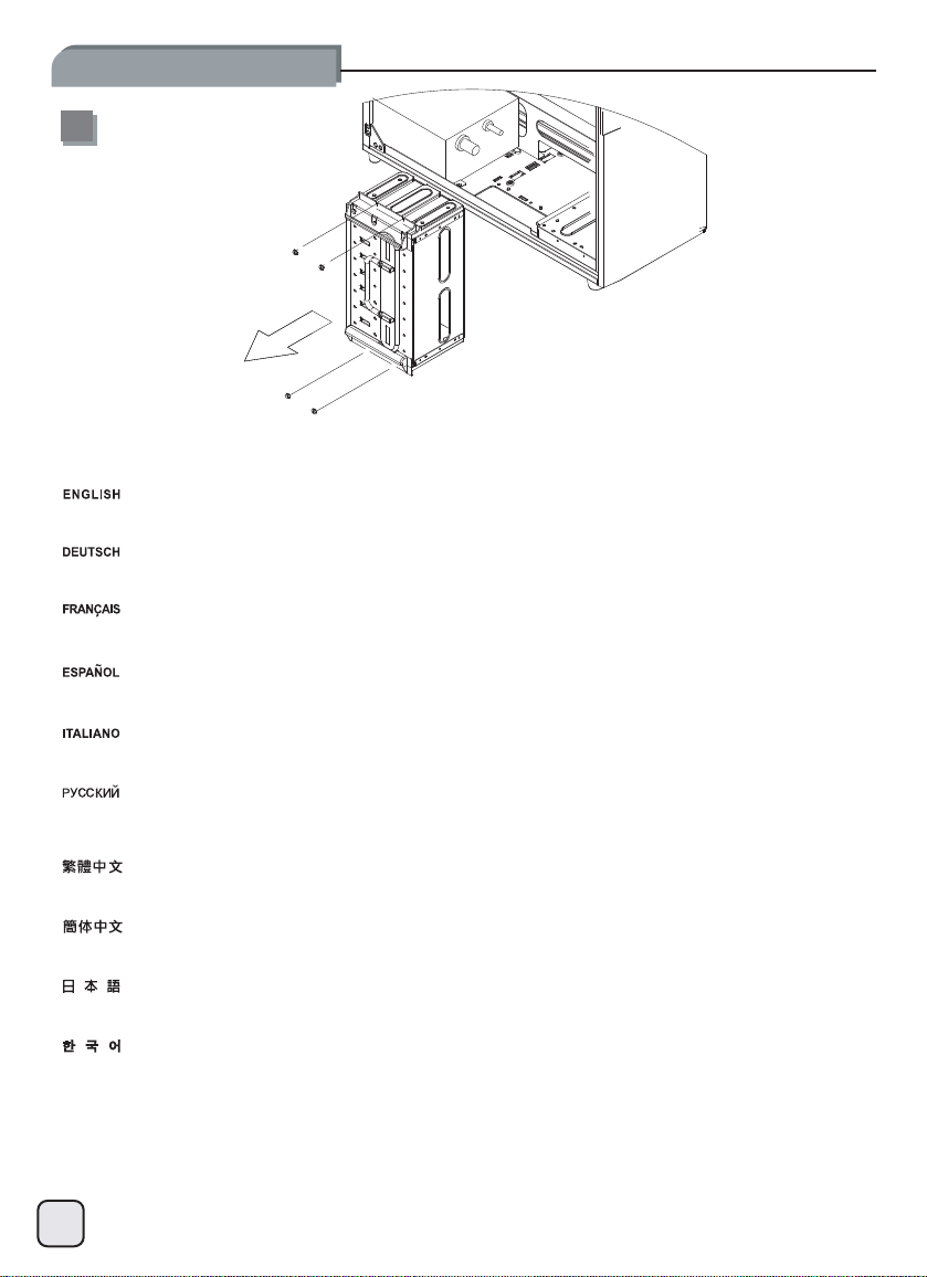
10
Remove 3.5” hard drive cage
Entfernen Sie den 3,5“-Festplattenkäfig.
Retirez la cage pour lecteur de disque dur 3,5 pouces.
Retire la carcasa para discos duros de 3,5”.
Rimuovere il supporto per hard drive da 3,5”.
Извлеките
移除3.5”硬碟架
移除3.5”硬盘架
3.5 ハードドライブケージを取り外します
3.5”하드 드라이브 케이스를분리하십시오.
корпус 3,5-дюймового
жесткого
11
диска
Page 13
lnstallation Guide
11
evird drah ”5.3DSS ro evird drah ”5.2
The 2.5” drive cage and a bottom fan will interfere with removal or installation of hard drive on the very bottom slot of the hard drive cage.
So we recommend installing the system drive into this slot to avoid having to remove it frequently. The bottom slot can be use
either 3.5” or 2.5” hard drive or SSD.
d to install
Der 2,5“-Laufwerkskäfig und der untere Lüfter werden behindernd wirken, wenn Festplatten im untersten Einbauplatz des Festplatt
figs installiert oder entfernt werden. Deshalb empfehlen wir, die Installation einer oft zu entfernenden System-Festplatte in d
Einbauplatz zu vermeiden. Der untere Einbauplatz kann für die Installation von 3,5“- oder 2,5“ Festplatten oder SSDs benutzt werden.
La cage de lecteur 2,5 pouces et le ventilateur inférieur risquent de gêner le retrait ou l’installation d’un disque dur dans l
inférieure de la cage. Il est par conséquent recommandé d’installer le lecteur système dans cette fente afin d’éviter des retraits trop
fréquents. La fente inférieure peut également être utilisée pour installer un disque dur de 3,5 pouces ou de 2,5 pouces, ou un
La carcasa para dispositivo de 2,5” y un ventilador inferior interferirán en la retirada ó instalación de un disco duro en el z
la carcasa para discos duros. Por tanto, le recomendamos que instale el disco de sistema en este zócalo para evitar tener que s
con frecuencia. El zócalo inferior se puede usar para instalar un disco duro ó SSD de 3,5” ó 2,5”.
Il supporto per hard drive da 2,5” in accoppiata con una ventola disposta sul fondo, può interferire con l’installazione o la r
hard drive nello slot più in basso. Vi consigliamo quindi di installare in questa posizione il disco di sistema, che è quello c
rimosso meno frequentemente. Lo slot più in basso può essere utilizzato, indifferentemente, per hard drive da 3,5” o 2,5” oppure SSD.
Корпус 2,5-дюймового
нижний отсек корпуса для
чтобы не извлекать его часто. Нижний отсек можно использовать
твердотельных дисков
最底層硬碟會受到2.5”硬碟架與底層風扇的阻擋,建議您在此安裝最不需要經常拆裝的系統硬碟,此空間可安裝3.5”或2.5”硬碟。
最底层硬盘会受到2.5”硬盘架与底层风扇的阻挡,建议您在此安装最不需要经常拆装的系统硬盘,此空间可安装3.5”或2.5”硬盘。
2.5”ドライブケージおよび底部ファンが、ハードドライブケージ最下部のスロットへのハードディスクの設置や除去の妨げとなる可
能性があります。それで、頻繁な交換を避けるためにこのスロットにはシステムドライブを設置するようお勧めします。一番下のスロ
ットは、3.5”と2.5”ハードディスクまたはSSDがインストール可能です。
2.5” 드라이브 케이스와 하단 팬은
따라서, 자주 분리하는 것을 피하려면 시스템 드라이브를 이
드라이브 또는 SSD 중
привода и
하나를
установки
(SSD).
설치할 수
нижний вентилятор
жестких дисков. Поэтому
드라이브 케이스 최하단 슬롯에서 하드
하드
있습니다.
создают трудности при извлечении
슬롯에
или установке
мы рекомендуем
для установки
설치하는 것이 좋습니다. 하단 슬롯을 사용하여 3.5” 또는 2.5” 하드
устанавливать в этот
3,5- ли 2,5-
드라이브를 분리하거나
дюймовых
жесткого диска в самый
отсек системный диск,
жестких дисков
설치하는 작업을 방해합니다.
enkä-
iesem
a fente
SSD.
ócalo inferior de
acarlo
imozione di un
he viene
или
12
Page 14
lnstallation Guide
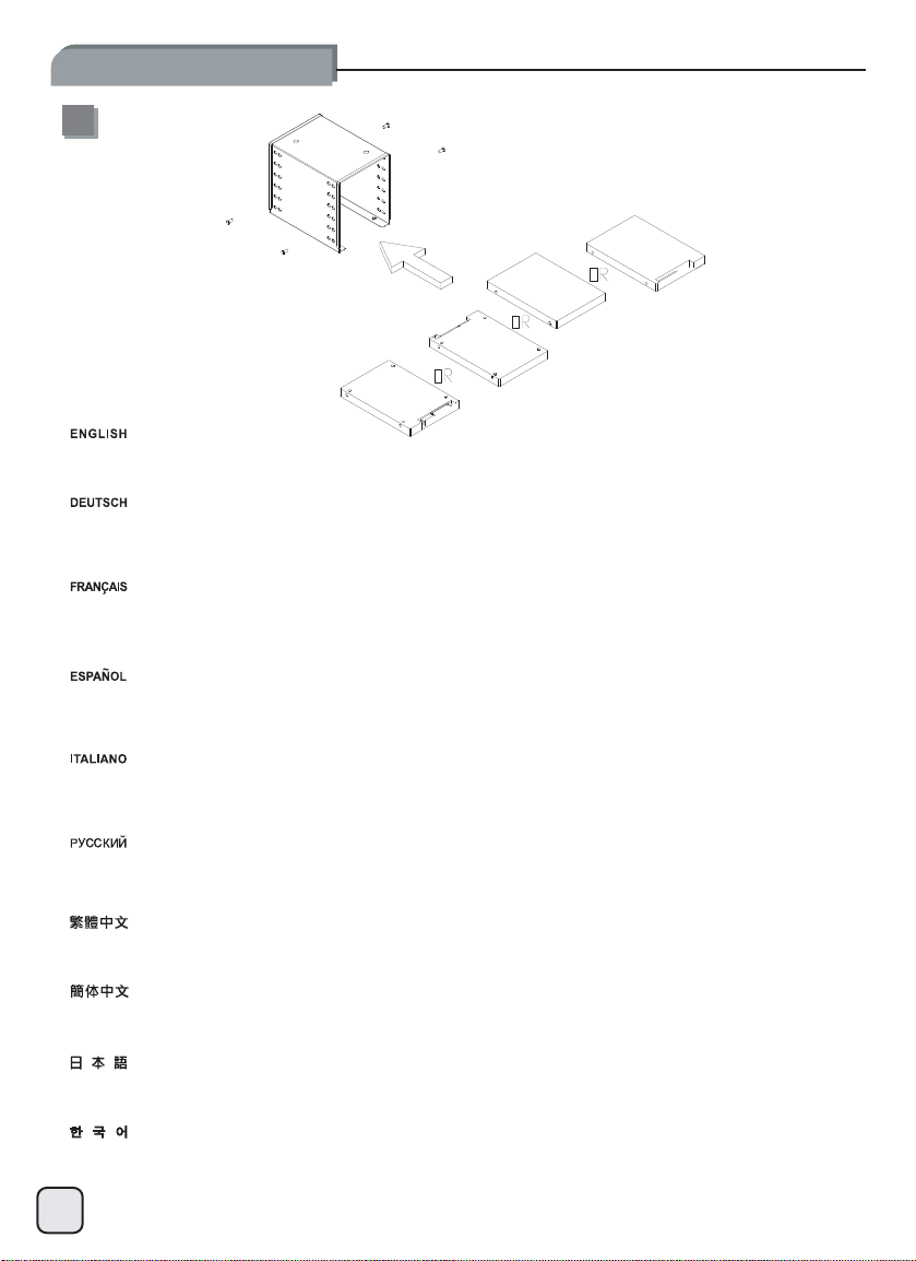
12
Install any 2.5” hard drive or SSD into the 2.5” drive cage as required. The cage is designed to accommodate 2.5” drives in regular
orientation or upside down in every slot to reduce cable clutter from installing numerous drives in one direction.
Installieren Sie beliebige 2,5“-Fesplatten oder SSDs im 2,5“-Laufwerkskäfig wie benötigt. Der Käfig ist dazu ausgelegt,
2,5“-Laufwerke in regulärer Ausrichtung oder umgedreht aufzunehmen um ein Durcheinander von Kabeln bei einer Installation von
vielen Laufwerken in einer Richtung zu reduzieren.
Selon vos besoins, insérez un disque dur ou SSD de 2,5 pouces dans la cage de lecteur 2,5 pouces. Chacune des fentes de la
cage est conçue pour accueillir un lecteur de 2,5 pouces à orientation classique ou inversée afin de minimiser l’encombrement des
câbles pouvant se produire avec l’installation de plusieurs lecteurs dans un même sens.
Instale cualquier disco duro de 2,5” ó SSD en la carcasa para discos de 2,5” según sea necesario. La carcasa está diseñada para
acomodar discos de 2,5” orientados de forma normal ó al revés en cada zócalo para reducir el desorden de cables producido al
instalar varios discos en una sola dirección.
Installare se necessario tutti gli hard drive da 2,5” o SSD nel supporto da 2,5”. Il supporto stesso è stato progettato per accogliere i
drive nell’orientamento standard o sottosopra per evitare l’accumulo di cavi derivante dall’installazione di più dischi orientati allo
stesso modo.
Установите
установки
уменьшения нагромождения проводов при установке приводов в
將2.5”硬碟安裝於2.5”硬碟架上,硬碟位置允許讓前後上下反裝;若您有大量2.5”硬碟,線材可能在小空間造成干涉,請斟酌讓
硬碟的方向全部錯開。
将2.5”硬盘安装于2.5”硬盘架上,硬盘位置允许让前后上下反装;若您有大量2.5”硬盘,线材可能在小空间造成干涉,请斟酌让
硬盘的方向全部错开。
2.5”ドライブケージには、必要に応じて任意の2.5”ハードドライブまたはSSDをインストールします。多数のドライブを単一の方向に取り付けるこ
とで生じる干渉を避けるよう、ケージは2.5”ドライブを通常の向きまたは裏返しにも収められるよう設計されています。
필요할 경우 특정한 2.5” 하드 드라이브
방향으로 설치할 때 케이블 클러터를 감소시키기 위해 모든 슬롯에서 규칙적인 방향이나 위 아래
2,5-дюймовый жесткий или твердотельный дисквкорпус 2,5-дюймового привода
2,5-дюймовых приводов со стандартным расположением
또는 SSD를 2.5” 드라이브 케이스에 설치하십시오. 이
수용하도록 설계되었습니다.
перевернутом
или в
одномитом
. Корпус предназначен для
положении в каждый отсек для
же положении.
케이스는 여러 드라이브를 한쪽
방향에 있는 2.5” 드라이브를
13
Page 15
lnstallation Guide
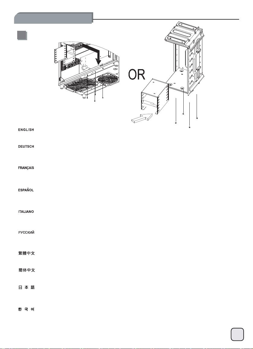
13
Install assembled 2.5” drive cage into the chassis, there are two screw holes provided for securing the cage. The 2.5” drive c
be installed into the 3.5” drive cage if power supply is too long and interferers with installation on the bottom of the chassi
Installieren Sie den bestückten 2,5“-Laufwerkskäfig im Gehäuse. Es sind zwei Schraubenlöcher zur Fixierung des Käfigs vorhanden. Der
2,5“-Laufwerkskäfig kann ebenfalls im 3,5“-Laufwerkskäfig installiert werden, falls ein Netzteil zu lang ist und eine Installation auf dem
Gehäuseboden verhindert.
Insérez la cage de lecteur 2,5 pouces assemblée dans le châssis ; deux orifices de fixation sont fournis pour la maintenir en place. La
cage de lecteur 2,5 pouces peut également être installée dans la cage de 3,5 pouces si le bloc d’alimentation est trop volumineux et
prévient une installation au bas du châssis.
Instale la carcasa montada para discos de 2,5” en el chasis, hay dos agujeros para tornillos que cumplen el objetivo de asegurar la
carcasa. La carcasa para discos de 2,5” también se puede instalar en la carcasa para discos de 3,5” si la fuente de alimentació
demasiado larga e interfiere con la instalación en la parte inferior del chasis.
Installare il supporto hard drive da 2,5” nel case, vi sono due fori per viti predisposti per l’ancoraggio. Il supporto da 2,5” può anche
essere installato all’interno di quello da 3,5” se l’alimentatore fosse troppo lungo ed interferisse con l’installazione sul fondo dello
chassis.
Установите собранный блок 2,5-дюймовых приводов в корпус системного
2,5-дюймовых приводов можно также установить в корпус 3,5-дюймовых приводов, если блок питания
создает трудности при установке в нижней части корпуса системного блока.
將2.5”硬碟架裝回機殼(有兩個鎖固位置,請依需求選擇);若電源深度太長,阻礙到原本2.5”硬碟架空間,可將硬碟架安裝至
3.5”硬碟架內。
将2.5”硬盘架装回机箱(有两个锁固位置,请依需求选择);若电源深度太长,阻碍到原本2.5”硬盘架空间,可将硬盘架安装至
3.5”硬盘架内。
組み上げられた2.5”ドライブケージをケースにインストールします。ケージを固定するために2つのネジ穴が備わっています。
電源が長過ぎてケース底部への設置に支障がある場合、2.5”ドライブケージは、3.5”ドライブケージ内に設置することもできま
す。
и закрепите его двумя
блока
винтами. Блок
слишком
age can also
s.
длинный
n es
и
조립한 2.5” 드라이브 케이스를 새시로 설치하십시오. 케이스를 고정시키기 위해 제공된 2개의 나사 구멍이 존재합니다.
전원 공급장치가 너무 길고 새시 하단에서의 설치 작업을 방해할 경우 2.5” 드라이브 케이스를 3.5” 드라이브 케이스에
설치할 수도 있습니다.
14
Page 16

lnstallation Guide
14
15
Install required 3.5” hard drives
into the 3.5” hard drive cage.
Installieren Sie benötigte
3,5“-Fesplatten im
3,5“-Festplattenkäfig.
Installez les lecteurs 3,5 pouces
requis dans la cage 3,5 pouces.
Instale los discos duros
necesarios de 3,5” en la carcasa
para discos duros de 3,5”.
Installare i necessari hard drive
da 3,5” nel supporto specifico.
Connect all cables required for
the installed 5.25”, 3.5”, and 2.5”
drives.
Установите 3,5-дюймовые
жесткие
3,5-дюймовых жестких дисков.
安裝3.5”硬碟至主硬碟架內。
安装3.5”硬盘至主硬盘架内。
必要な3.5”ハードドライブをハ
ードドライブケージに装着します
필요한 3.5” 하드 드라이브를
3.5” 하드 드라이브 케이스로
설치하십시오.
Подключите все кабели
установленных
2,5-
дюймовых приводов.
диски в
корпус блока
для
5,25-, 3,5- и
15
Verbinden Sie alle benötigten
Kabel für die installierten 5,25“-,
3,5“-, und 2,5“-Laufwerke.
Branchez tous les câbles
nécessaires à l’installation des
lecteurs 5,25 pouces, 3,5 pouces
et 2,5 pouces.
Conecte todos los cables
necesarios para los dispositivos
instalados de 5,25”, 3,5” y 2,5”.
Connettere tutti i cavi necessari ai
drive da 5,25”, 3,5” e 2,5”
連接上所有磁碟所需的線材
(包含5.25”、3.5”、2.5”)
连接上所有磁盘所需的线材
(包含5.25”、3.5”、2.5”)
装置された5.25”、3.5”および
2.5”ドライブに必要な全てのケ
ーブルを接続します。
설치한 5.25”, 3.5” 및 2.5”
드라이브에 필요한 모든
케이블을 연결하십시오.
Page 17

lnstallation Guide
16
17
Install the assembled 3.5” drive
cage back into the chassis and
pay attention to cable routing
while doing so.
Installieren Sie den bestückten
3,5“-Laufwerkskäfig wieder im
Gehäuse und achten Sie auf die
Kabelverlegung während diesem
Vorgang.
Insérez la cage de lecteur 3,5
pouces assemblée dans le
châssis en veillant à soigneusement acheminer le câblage.
Instale la carcasa montada para
discos de 3,5” de nuevo en el
chasis y preste atención al
enrutado de cables mientras lo
hace.
Installare quindi il supporto hard
drive all’interno del case facendo
attenzione alla sistemazione dei
cavi.
Reinstall both side panels back
onto the chassis to complete
installation.
Установите собранный блок
дюймовых приводов в
3,5-
корпус системного блока,
уделяя при этом внимание
прокладке кабелей.
將3.5”硬碟架裝回機殼,請注意
理線。
将3.5”硬盘架装回机箱,请注意
理线。
組み上げられた3.5”ドライブケ
ージをケースに戻し、その際ケー
ブル取り回しに注意を払います。
조립한 3.5” 드라이브 케이스를
새시에 다시 설치하고 설치
작업을 수행하는 동안 케이블
연결 상태에 주의를
기울이십시오.
Установите на место боковые
панели
системного блока для
завершения
установки
.
Befestigen Sie die beiden
Seitenwände am Gehäuse um die
Installation abzuschließen.
Remettez en place les deux
panneaux latéraux du châssis
pour terminer l’installation.
Reinstale ambos paneles
laterales de nuevo en el chasis
para completar la instalación.
Riposizionare i pannelli laterali ed
assicurarli allo chassis per
completare l’installazione.
裝回左右側板,完成組裝。
装回左右侧板,完成组装。
両方のサイドパネルをケースに戻
すと、インストールは完了です。
양쪽 패널을 새시에 다시
설치하여 설치를 완료하십시오.
16
Page 18

Connector Definition
(1) Front panel connector installation
POWER SWITCH
Power switch and reset switch installation guide:
Please refer to the motherboard manuals for the motherboard’s “Front Panel Connector” or “System Panel Connector”
pin definition. Power switch and reset switch have no polarity, so they can be connected in any orientation.
Ein-/Ausschalter und Rücksetztaste (Reset) installieren:
Bitte suchen Sie in der Motherboard-Dokumentation nach der Pinbelegung der Anschlüsse des Frontbedienfeldes
(„Front Panel Connectors“ oder „System Panel Connectors“). Ein-/Austaste und Rücksetztaste benötigen keine bestimmte Polarität, können
daher beliebig (ohne auf + und - zu achten) angeschlossen werden.
Guide d'installation des interrupteurs d'allumage et de réinitialisation :
Veuillez-vous référer au manuel de votre carte mère pour la description des broches "des connecteurs du panneau frontal" et des broches
"des connecteurs du panneau système". Les interrupteurs d'allumage et de réinitialisation ne possède pas de polarité, donc ils peuvent être
branché dans les deux sens.
Guía de instalación de los interruptores de encendido y reseteo:
Por favor, consulte en los manuales de la placa base la configuración de pines del “Conector de panel frontal” ó “Conector de panel de
sistema” de su placa base. Los interruptores de encendido y reseteo no tienen polaridad, luego se pueden conectar con cualquier
orientación.
Guida all’installazione dei connettori Power Switch e Reset Switch
Fare riferimento al manuale della scheda madre nella sezione “Connettori del pannello frontale” o “Connettori del pannello di sistema”. Power
switch e reset switch non hanno polarità, posso essere pertanto connessi con qualsiasi orientamento.
Инструкция по подключению выключателя питания и кнопки перезагрузки (reset):
контактов
Описание
пользователя материнской платы.
в
любой ориентации.
разъемов приведены в разделах “Разъемы передней панели
Выключатель
питания и
кнопка
RESET SWITCH
перезагрузки не
” или “
имеют
системной
Разъемы
полярности, поэтомуихможно подключать
панели” руководства
Power Switch
請參考主機說明書的Front Panel Connectors安裝Pin Define,將Connector
不影響功能性。
Power Switch
请参考主机说明书的Front Panel Connectors安装Pin Define,将Connector
不影响功能性。
電源スイッチおよびリセットスイッチのインストールガイド:
マザーボードの「フロントパネルコネクタ」または「システムパネルコネクタ」のピン配列についてはマザーボードマニュアルを参照して
ください。電源スイッチとリセットスイッチに極性はないので、いずれの方向でも接続できま。
파워 스위치 및 리셋 스위치 설치 가이드
메인보드 매뉴얼의 전면패널 커넥터 혹은 시스템패널 커넥터 핀을 참조하기 바랍니다. 파워 스위치와 리셋 스위치는 극성이 없어 어떤
방향으로 설치해도 무방합니다.
與Reset Switch
与Reset Switch
安裝說明:
安装说明:
插上;Power Switch
插上;Power Switch
與Reset Switch
与Reset Switch并无正负极性之分,反插正插都
並無正負極性之分,反插正插都
17
Page 19

Connector Definition
(1) Front panel connector installation
POWER LED-
POWER LED+
LED connector installation guide:
Please refer to the motherboard manuals for the motherboard’s “Front Panel Connector” or “System Panel Connector” pin definition.;the
white wires are negative while other colors are positive wires. The Power LED wires are separate pins for compatibility with different
motherboard pin definition so please make sure they are connected in the right polarity by referring to your motherboard manual.
LED-Verbinder installieren:
Bitte suchen Sie in der Motherboard-Dokumentation nach der Pinbelegung der Anschlüsse des Frontbedienfeldes
(„Front Panel Connectors“ oder „System Panel Connectors“). Die weißen Adern sind negativ (-), die farbigen Adern positiv (+).Die Kabel für
die Betriebsanzeige-LED sind zur Kompatibilität mit unterschiedlichsten Motherboards einzeln, nicht als kompletter Stecker ausgeführt.
Achten Sie hier bitte auf die richtige Polarität, lesen Sie in der Dokumentation Ihres Motherboards nach.
Guide d'installation du connecteur LED :
Veuillez-vous référer au manuel de votre carte mère pour la description des broches "des connecteurs du panneau frontal" et des broches
"des connecteurs du panneau système". Les câbles colorés en blanc sont négatifs alors que ceux d'une autre couleur sont positifs.Les câbles
de la LED Power sont séparés afin d'être compatible avec différentes cartes mères, donc vérifiez bien qu'ils sont branchés avec la bonne
polarité en vous référant au manuel de votre carte mère.
Guía de instalación del conector LED:
Por favor, consulte en los manuales de la placa base la configuración de pines del “Conector de panel frontal” ó “Conector de panel de
sistema” de su placa base. Los cables de color blanco son negativos mientras que los de color son positivos. Los cables LED de potencia
tienen pines separados para compatibilidad con diferentes definiciones de pines de la placa base luego por favor, asegúrese de que están
conectados en la polaridad correcta consultando el manual de su placa base.
Guida all’installazione del connettore LED:
Fare riferimento al manuale della scheda madre nella sezione “Connettori del pannello frontale” o “Connettori del pannello di sistema”. I cavi
di colore bianco sono il polo negativo, mentre quelli di colore diverso il positivo.Guida all’installazione del Power Led serie RV/KLConnettere
direttamente il connettore ad un molex dell’alimentatore.
Инструкция по
Описание
пользователя материнской
Провода
материнских плат, поэтому
подключению
контактов
светодиодного индикатора питания имеют отдельные
коннектора для светодиодного индикатора питания
разъемов приведены в разделах
Белые
платы.
обратитесь к
провода - отрицательной
руководству пользователя
“Разъемы
передней панели”или “Разъемы
полярности, цветные
контакты
материнской
HDD LED+
HDD LED-
:
для совместимости с различными типами контактов
платыиубедитесь
системной
провода - положительной полярности.
панели” руководства
, что
полярность с облюдена.
LED
接頭安裝說明:
請參考說明書的Front Panel Connectors安裝Pin Define
各主機板的不同,特別設計為散Pin樣式,請安心使用。
LED接口安装说明:
请参考说明书的Front Panel Connectors安装Pin Define
主机板的不同,特别设计为散Pin样式,请安心使用。
LEDコネクタのインストールガイド:
マザーボードの「フロントパネルコネクタ」または「システムパネルコネクタ」ピン配列についてはマザーボードマニュアルを参照してく
ださい。白色のリード線はマイナスで、色の着いたリード線がプラスです。電源LEDリード線は種々のマザーボードピン定義と互換性を持
たせるため分離されたピンとなっているので、ご使用のマザーボードマニュアルを参照して、 適切な極性に接続されるようお確かめくださ
い。
LED
커넥터 설치 가이드
메인보드 매뉴얼의 전면패널 커넥터 혹은 시스템패널 커넥터 핀을 참조하기 바랍니다. 하얀선의 경우 음극이며, 다른 색의 경우
양극입니다. 파워 LED 선은 분리되어 다양한 메인보드에서 동작할 수 있도록 되어 있습니다. 그러므로 메인보드 매뉴얼을 참조하여
올바를 극성을 주의해 선택하시기 바랍니다.
,將Connector
,将Connector
插上;白色線的部分為負極,彩色線的部分是正極。
插上;白色线的部份为负极,彩色线的部份为正极。
Power LED為了適應
Power LED为了适应
18
Page 20

Connector Definition
(2) Front I/O connector installation
Below are the front I/O connectors pin definition, please also check your motherboard manual to cross reference with motherboard’s front
I/O pin headers. SilverStone’s I/O connectors are in block type to simplify installation.
Nachstehend finden Sie die Pinbelegung der vorderen E/A-Anschlüsse; bitte gleichen Sie zudem das Handbuch Ihres Motherboards mit
den vorderen E/A-Pinzuweisungen ab. SilverStones E/A-Anschlüsse befinden sich zur Vereinfachung der Installation in Blockart.
Au dessous de la description des broches des ports d'E/S, veuillez aussi vérifier sur le manuel de votre carte mère de manière croisée que
les broches sont correctement placées. Les connecteurs d'E/S de SilverStone sont en bloc pour en simplifier leur installation.
A continuación se detallan los pines para conectores E/S frontales, compruebe también por favor el manual de su placa base para cotejar
los pines E/S frontales de la misma. Los conectores E/S de SilverStone son del tipo bloque para simplificar la instalación.
Di seguito lo schema delle connessioni I/O frontali, confrontare lo schema con quanto riportato sul manuale della scheda madre
effettuare un controllo incrociato. I connettori I/O Silverstone, per semplificare l’installazione, sono del tipo “a blocco”.
Ниже приведено описание контактов передних разъемов ввода/вывода
материнской платы за описанием
типа
блочного
下表為
TJ04-E的Front I/O Connectors
下表为Front I/O Connectors的Pin Define
TJ04-E的Front I/O Connectors完全采用集合Pin方式以简化安装。
以下はフロントI/Oコネクタピン配列ですが、お持ちのマザーボードのフロント
。シルバーストーンのI/Oコネクタは、インストールの容易なブロックタイプになっています。
아래는 전면 I/O 커넥터의 핀 사양입니다. 메인보드 매뉴얼을 참조해, 메인보드의 전면 I/O
후 설치합니다. SilverStone의 I/O 커넥터는 블록 타입으로 구성되어 있어 간편한 설치가 가능합니다.
, что облегчает
Front I/O Connectors的Pin Define
передних разъемов ввода
сборку
.
,請參閱主機板說明書的各Front I/O Connectors Pin Define
完全採用集合
Pin方式以簡化安裝。
,请参阅主机板说明书的各
USB 3.0 TO USB 2.0
CONVERTER CABLE
/вывода типа "пин
. Обратитесь также
-хедер".
Разъем ы
Front I/O Connectors Pin Define
I/Oピンヘッダは、マザーボードマニュアルをご参照ください
핀사양을 재 확인한
USB 3.0 CONNETOR USB 2.0 CONNETOR
к руководству пользователя
ввода/вывода
一一核對。
一一核对。
"SilverStone" -
per
19
Page 21

Component Size Limitations
The TJ04-E can accommodate all standard size components and even some that are slightly out of spec.,
please refer to the following guidelines for component selection and future upgrade considerations.
Tip
(1) CPU cooler height limitation
The height limit is 168mm (164mm for TJ04-E with window side
panel) and there is 15mm of clearance around the motherboard.
Das Höhenlimit beträgt 168 mm (164 mm für das TJ04-E mit
einem Fenster in der Seitenwand) und es gibt 15 mm Freiraum
um das Mainboard herum.
La hauteur maximale est de 168mm (164mm pour TJ04-E avec
panneau latéral de type fenêtre) et il existe un dégagement de
15mm autour de la carte mère.
La altura límite es de 168mm (164mm para la TJ04-E sin el
panel lateral con ventana) y existe un espacio libre de 15mm
alrededor de la placa base.
L’altezza limite corrisponde a 168mm (164mm per il TJ04-E con
il pannello dotato di finestra trasparente) e vi sono 15mm di
tolleranza intorno alla scheda madre.
Ограничение по высоте составляет
вокруг системной платы.
мм (164 мм для TJ04-E
168
с окном в
WE-B4
0JT
CPU cooler height limit figure
боковой панели) и
15 ммсвободного
Clearance 15mm Clearance 15mm
Maximum 168 mmMaximum 164 mm
E-B40JT
пространства
Cooler限高是168mm(開窗版本是164mm),Cooler
Cooler限高是168mm(开窗版本是164mm),Cooler
高さ制限は168mm(ウインドウサイドパネル付きのTJ04-Eでは164mm)で、15mmの余裕がマザーボードのまわりにあります
높이 한계는 168mm(윈도우 측면 패널이 있는 TJ04-E의 경우 164mm) 이며 메인보드 주위에는 15mm 간격이 존재합니다.
外緣允許超出主機板上邊界15mm
外缘允许超出主机板上边界15mm
20
Page 22

Component Size Limitations
The TJ04-E can accommodate all standard size components and even some that are slightly out of spec.,
please refer to the following guidelines for component selection and future upgrade considerations.
Tip
(2) Power supply limitation
A: Depth limitation
If both 2.5” drive cage and bottom fan are not installed, then there are literally no power supply depth limitations.
If either 2.5” drive cage or bottom fan is installed, the limitation will be 180mm or 160mm if extra cabling room is required.
A: Tiefenbeschränkung
Falls beide 2,5“-Laufwerkskäfige und der untere Lüfter nicht installiert sind,
gibt es buchstäblich keine Limitierung der Netzteiltiefe. Falls entweder ein
2,5“-Laufwerkskäfig oder der untere Lüfter installiert sind, beträgt die
Limitierung 180 mm oder 160 mm im Falle, dass zusätzlicher Freiraum für
Kabel benötigt wird.
A: limitation de profondeur.
Si la cage de lecteur 2,5 pouces et le ventilateur inférieur ne sont pas
installés, il n’existe aucune limitation de profondeur pour le bloc
d’alimentation. Si la cage de lecteur 2,5 pouces ou le ventilateur inférieur
est installé, la limitation sera de 180mm ou de 160mm si un espace de
câblage supplémentaire est requis.
A: Limitación de profundidad
Si la carcasa para discos de 2,5” y el ventilador inferior no han sido
instalados, entonces no existen limitaciones a la profundidad de la fuente
de alimentación. Si la carcasa para discos de 2,5” ó el ventilador inferior
han sido instalados, la limitación será de 180mm ó 160mm si hace falta el
espacio extra para los cables.
A: Limitazioni di profondità
Se il supporto per drive da 2,5” e la ventola disposti sul fondo non sono installati, non vi è alcuna limitazione. Se invece vengono installati, la
limitazione è di 180mm o 160mm se è necessario spazio aggiuntivo per i cavi.
Recommend 160 mm
PSU
Maximum 180 mm
Power supply limitation figure
A:
Ограничение по глубине
Если
не устанавливаются блок 2,5-дюймовых
При установке блока
дополнительное
A:長度限制
如果底層沒有安裝2.5”硬碟架與風扇,電源就幾乎沒有長度限制,您可以使用任何超大瓦數的電源
如果電源前方有安裝2.5”與風扇,我們建議您使用160mm以內的電源
最極限長度會是180mm
A:长度限制
如果底层没有安装2.5”硬盘架与风扇,电源就几乎没有长度限制,您可以使用任何超大瓦数的电源
如果电源前方有安装2.5”与风扇,我们建议您使用160mm以内的电源
最极限长度会是180mm
A: 長さ制限
2.5”ドライブケージと最下部のファン共にインストールされていなければ、実質上電源長さ限界はありません。
2.5”ドライブケージまたは最下部のファンがインストールされている場合、余分のケーブル取り回しが必要とされるならば、制限は18
または160mmです。
A: 깊이 제한
2.5” 드라이브 케이스와 하단 팬을 모두 설치하지 않은 경우, 사실상 전원 공급장치 깊이 제한이 없습니다.
2.5” 드라이브 케이스 또는 하단 팬 중 하나를 설치할 때 여분의 케이블 공간이 필요할 경우 전원 공급장치 깊이 제한은 180mm 또는
160mm입니다.
2,5-
дюймовых
пространство
для размещения
приводов и
приводов или нижнего
кабелей.
вентилятор
нижний
вентилятора ограничение составляет 180
ограниченийпоглубине
, то
установки
мм или 160
практически
мм, если требуется
21
нет.
0mm
Page 23

Component Size Limitations
(2) Power supply limitation
B: Cable length recommendations
Below is a table of recommend cable length based off of common retail power supplies. Please make sure that the power supply you want to
use has long enough cables to fit the below recommendations or you can also choose to purchase additional power cable extensions:
B: Empfohlene Kabellänge
Nachstehend finden Sie eine Tabelle der empfohlenen Kabellänge basierend auf handelsüblichen Netzteilen. Bitte stellen Sie sicher, dass
das von Ihnen gewählte Netzteil entsprechend der nachstehenden Empfehlungen über ausreichend lange Kabel verfügt; alternativ können
Sie zusätzliche Netzkabelverlängerungen kaufen.
B: Longueur des cables
Vous avez ci dessous un tableau avec la longueur des cables recommandes base sur les alimentations du marche. Veuillez bien verifier
que l'alimentation que vous allez utiliser possede bien des cables assez long pour etre compatible avec ces recommandations. Sinon vous
pouvez choisir d'acheter des rallonges.
B: Recomendación de la longitud de los cables de la FA
A continuación hay una tabla con la longitud recomendada de los cables basada en fuentes de alimentación comunes. Por favor, asegúrese
de que la fuente de alimentación que quiere usar tiene cables lo bastante largos como para adecuarse a las recomendaciones siguientes, en
caso contrario puede decidir comprar extensiones adicionales para cables de potencia.
B: Raccomandazioni sulla lunghezza dei cavi della PSU
La tabella di seguito mostra le lunghezze dei cavi raccomandate e si basa sulle misure dei cavi con riferimento ai comuni alimentatori retail.
Assicuratevi che l’alimentatore che avete intenzione di utilizzare risponda alle caratteristiche richieste, altrimenti considerate l’acquisto di un
kit di prolunga cavi.
B: рекомендации по длине кабелей
В следующей таблице представлены рекомендованные значения
источников
в противном
B:電源線材建議長度:
以下是以一般市售ATX主機板抓出來的各線材建議長度列表,請先確認電源線長度是否足夠,如果不夠請選購所需要的延長線。
B:电源线材建议长度:
以下是以一般市售ATX主机板抓出来的各线材建议长度列表,请先确认电源线长度是否足够.如果不够请选购所需要的延长线.
B:電源ケーブル推奨長さ:
下記は、一般の小売り電源の推奨ケーブル長さの表です。使いたい電源が下記の推奨基準に合った、十分の長さのケーブルを持っていること
を確認してください。または電源用の延長ケーブルを購入することもできます。
B: 추천 케이블 길이
아래 표에서는 일반적으로 판매되는 파워 서플라이의 추천 케이블 길이를 표시해 놓았습니다. 사용하고자 하는 파워 서플라이가
아래의 추천길에에 충분한 케이블을 갖추고 있는지 확인하시기 바라며, 필요시에는 추가의 연장 파워 케이블 구입이 가능합니다.
питания. Убедитесь, что
случае можно
приобрести
длина
кабелей источника
дополнительные удлинители кабеля источника питания.
Cable type and location
EPS 8pin/ATX4pin (from left side of PSU)
длины
кабелей на основе значений имеющихся в продаже
питания достаточна
и соответствует следующим рекомендациям
Minimum length
550mm
ATX 24Pin (from left side of PSU) 300mm
SATA 15Pin (behind motherboard tray to top
most optical drive)
SATA 15Pin (to top most 3.5” drive cage)
SATA 15Pin (to 2.5” drives cage)
PCI-E 6/8pin (behind motherboard tray to first
expansion slot)
400mm
550mm
50mm
450mm
,
22
Page 24

Component Size Limitations
(3) Graphics card/expansion card length limitation
If no hard drive is installed in front of the graphics card, the length limit is 17”
If hard drive is installed, the graphics card length limit is 12.8”
Graphic Card Length Reference:
AMD Radeon HD 5970 – 12.2 "
AMD Radeon HD 5870 6950 6970 – 11”
NVidia Geforce GTX480 580 570 – 10.5”
Falls keine Festplatte vor der Grafikkarte installiert ist beträgt das Längenlimit 17“.
Falls eine Festplatte installiert ist beträgt das Limit der Grafikkartenlänge 12,8“.
Si aucun lecteur n’est installé devant la carte graphique, la longueur maximale est de 17 pouces
Si un lecteur est installé, la longueur maximale de la carte graphique est de 12,8 pouces
Si no existe un disco duro instalado frente a la tarjeta gráfica, la longitud límite es de 17”
Si existe un disco duro instalado, el límite de longitud de la tarjeta gráfica es de 12,8”
Se di fronte alla scheda grafica, non sono installati hard drive, la limitazione è di 17” (43,18cm)
Se invece sono installati hard drive, la limitazione scende a 12,8” (32,51cm)
Если перед графическ ой
Если жесткий
如果顯示卡前方槽位沒有硬碟,該顯示卡可以安裝到17”
如果有硬碟,最大長度12.8”
如果显示卡前方槽位没有硬盘,该显示卡可以安装到17”
如果有硬盘,最大长度12.8”
диск
картой не
установлен, длина графической к артынедолжна превышать
установлен
жесткий
ограничение на
диск,
AMD Radeon HD 5850 – 9.5””
NVidia Geforce GTX470 – 9.5”
длину составляет
дюйма
12,8
17 дюймов (43,2
(32,5 см)
см)
ハードディスクがグラフィックスカードの前に装着されないならば、長さ制限は17インチです。
ハードディスクが装着されるならば、グラフィックスカードの長さ制限は12.8インチです。
그래픽 카드 전면에 하드 드라이브를 설치하지 않은 경우, 길이 한계는 17"입니다.
하드 드라이브를 설치한 경우, 그래픽 카드 길이 한계는 12.8"입니다.
23
Page 25

Component Size Limitations
(4) Motherboard size limitation
Although TJ04-E was not designed for Extended-ATX motherboard, the internal space can still allow installation for motherboards with width
of up to 11 inches. In addition, the motherboard tray has mounting standoffs for supporting SSI-CEB dual CPU motherboards. Enthusiast
motherboards such as ASUS’s Rampage III Extreme and EVGA’s X58 Classified 4-Way SLI are 10.6 and 10.375 inches wide respectively.
These are wider than standard ATX motherboard specification of 9.6 inches, but will fit inside TJ04-E without any problems. Even if there are
SATA connectors mounted on the edge of the motherboard facing to the side, the TJ04-E will have room to accommodate them as well.
Obwohl das TJ04-E nicht zur Verwendung von Extended-ATX-Motherboards entworfen wurde, ermöglicht der Platz im Gehäuseinneren di
Installationeines Motherboards mit einer Breite von bis zu 27,94 cm. Der Motherboard-Einschub verfügt zudem zur Unterstützung
SSI-CEB-Dual-CPU-Motherboards über Montageabstandshalter. Liebhaber-Motherboards, wie das Rampage III Extreme und EVGA X58
Classified 4-Way SLI von ASUS haben eine Breite von 26,92 bzw. 26,35 cm. Damit sind sie breiter als die Spezifikationen von St
Motherboards (24,38 cm), passen jedoch problemlos in das TJ04-E. Auch wenn SATA-Anschlüsse so am Motherboard montiert sind, da
zur Seite zeigen, bietet das TJ04-E ausreichend Platz.
Le TJ04-E n'est pas conçu pour les cartes mères de format Extended-ATX. Cependant, l'espace intérieur permet l'installation de cartes
mères dont la largeur ne dépasse pas les 27,94 cm. En outre, le porte-carte mère est doté de dispositifs de montage vertical, permettant de
maintenir deux cartes mères pour unité centrale de format SSI-CEB. Les cartes mères les plus puissantes, comme les cartes Ramp
Extreme d'ASUS et X58 Classified 4-Way SLI d'EVGA, font respectivement 26,924 et 26,3525 cm de large. Elles sont plus larges q
spécification ATX des cartes mères, soit 24,384 cm, mais rentrent sans problème dans le TJ04-E. Même si des connecteurs SATA sont
disponibles sur les bords de la carte mère, vers le côté, le TJ04-E dispose de suffisamment d'espace pour loger ces cartes.
Aunque la TJ04-E no fue diseñada para placas base Extended-ATX, el espacio interno permite instalar placas base con una anchura de
hasta 11 pulgadas. Además, la bandeja para la placa base tiene bases de montaje para placas base de CPU duales SSI-CEB. Las placas
base para grandes apasionados de la potencia, como la Asus Rampage III Extreme y la X58 Classified 4-Way SLI de EVGA, tienen 10,6” y
10,375” de ancho, respectivamente. Ambas son más anchas que las especificaciones para placas base ATX estándar de 9,6”, pero en
dentro de la TJ04-E sin problemas. Aunque haya conectores SATA montados en el lado colindante de la placa base, la TJ04-E seguirá
teniendo espacio para acomodarlas.
Sebbene TJ04-E non sia stato progettato per accogliere schede madri in formato Extended-ATX, lo spazio interno permette il mont
mainboard profonde fino a 27,94cm (11 pollici). Il supporto dispone inoltre di standoff disposti in modo da supportare anche sc
SSI-CEB dual CPU. Mainboard per appassionati come la Asus Rampage III Extreme e la EVGA X58 Classified 4-Way SLI sono larghe
rispettivamente 26,92cm (10.6 pollici) e 26,35cm (10.375 pollici) ma trovano comodamente posto all’interno di TJ04-E. Anche se i connettori
SATA sono disposti nell’angolo destro in basso e orientati lateralmente, viè abbastanza spazio per gestire comodamente le conne
von
andard-ATV-
ss sie
age III
ue la
aggio di
hede madri
ssioni.
e
trarán
Illustration: ASUS Rampage III Extreme is wider than standard ATX motherboards
24
Page 26

Component Size Limitations
(4) Motherboard size limitation
корпус TJ04-E
Хотя
позволяет устанавливать материнские платы шириной до 11 дюймов. Кроме
крепежными выступами для поддержки двухпроцессорных
таких как ASUS Rampage III Extreme и EVGA X58 Classified 4-Way SLI, составляет 10,6 и 10,375 дюйма, соответственно. Их
превышает специфик ацию для материнских плат ATX, составляющую 9,6 дюйма, но он без проблем помещаются в корпус TJ04-E.
Даже если
размещения.
TJ04-E雖然尚未支援到E-ATX主機板,但是內部的空間允許最大寬度到11”的主機板。因此我們的主機板螺柱設計到支援
機板。而一般玩家級ATX主機板也有如ASUS Rampage III Extreme或EVGA X58 Classified 4-Way SLI深度達到10.6”
長度達到13.6”;此外,主機板前方
TJ04-E虽然尚未支持到E-ATX主机板,但是内部的空间允许最大宽度到11”
机板。而一般玩家级ATX主机板也有如
长度达到13.6”
TJ04-Eは拡張ATX マザーボード用に設計されてはいませんが、内部空間は最大11インチ幅のマザーボードがインストールできます。さらに
、SSI-CEBデュアルCPUマザーボードに対応して、マザーボードトレイには取付けスペーサーが装備されています。
ExtremeおよびEVGA製X58 Classified 4-Way SLI
ド仕様より幅が広いものの、TJ04-Eへのインストールには全く問題ありません。マザーボードの縁に実装された側面に向いたSATA
があっても、TJ04-Eにはそれらを適応させる余裕があります。
비록 TJ04-E이 Extended ATX 메인보드를 위해 디자인 되지 않았지만, 내부공간에최대 11인치의 메인보드를
있습니다. 추가로 메인보드 트레이는 SSI-CEB 메인보드를 지원하는 마운팅지지나사를
Rampage III Extreme 또는 EVGA X58 Classified 4-Way SLI 는각각 10.6 과 10.375
메인보드의 규격인 9.6
측면을 보고 있는
не предназначен
разъемы SATA
;此外,主机板前方
인치를 상회하고
경우에도 충분한 공간이
для материнских плат
установлены на
SATA Connector
ASUS Rampage III Extreme或EVGA X58 Classified 4-Way SLI
SATA Connector所需要的预留空间,将造成普通ATX机壳无法安装此类主机板,但TJ04-E均可以正常支持。
материнской платы
краю
所需要的預留空間,將造成普通
は、それぞれ10.6インチと10.375
TJ04-E에는
있지만
확보되어 사용에 문제가 없습니다.
-фактора Extended-ATX, размер внутреннего пространства все же
форм
материнских плат SSI-CEB. Ширина высококлассных материнских плат,
장착이
문제없이
того,кронштейн материнской платы оснащен
корпусе TJ04-E будет
, в
ATX 機殼無法安裝此類主機板,但TJ04-E均可以正常支援。
的主机板。因此我们的主机板螺柱设计到支持SSI-CEB
インチ幅です。これらは標準の9.6インチATX マザーボー
지원합니다. 매니아층에서 많이
인치 넓이를
가능합니다. 만약 SATA 커넥터가 메인보드 가장자리에
свободное
иметься
深度达到
갖고 있습니다. 이들은 표준 규격의 ATX
пространство
SSI-CEB
,超出正常
10.6”,超出正常9.6”的尺寸,且
ASUS製Rampage III
수있는
수용할
사용하는
공간이
ширина
для их
規格的雙CPU主
9.6”的尺寸,且
CPU主
规格的双
コネクタ
확보되어
ASUS
TJ04-E의
25
Illustration: ASUS Rampage III Extreme is wider than standard ATX motherboards
Page 27

Component Size Limitations
(4) Motherboard size limitation
New generation of SSI-CEB server or workstation motherboards no longer require CPU cooler mounting holes on the motherboard tray.
Coolers can now be installed directly on the motherboard. As a result, we eliminated support for SSI-CEB CPU cooler mounting holes
and instead increased the large gap on the motherboard tray to support CPU cooler back plates swapping with more LGA 1156/1155
motherboards. The TJ04-E chassis’ support for new and future SSI-CEB motherboards should be unaffected by this change.
Hochmoderne Motherboards von SSI-CEB-Servern und -Arbeitsrechnern benötigen keine Löcher zur CPU-Kühlermontage am MotherboardEinschub mehr. Die Kühler können nun direkt am Motherboard installiert werden. Dadurch haben wir die Unterstützung der Löcher zur
SSI-CEB-CPU-Kühlermontage aufgegeben und stattdessen den Abstand am Motherboard-Einschub vergrößert; dadurch werden CPUKühlerrückplatten unterstützt, die mit einer größeren Anzahl an LGA 1156-/1155-Motherboards kompatibel sind. Die Unterstützung neuer
und zukünftiger SSI-CEB-Motherboards durch das TJ04-E-Gehäuse wird durch diese Änderung nicht beeinflusst.
Les portes-carte mère destinés à la nouvelle génération de cartes mères pour station de travail ou serveur SSI-CEB n'ont plus besoin de trous
de montage pour le refroidisseur de l'unité centrale. Les refroidisseurs peuvent désormais s'installer directement sur la carte mère. Nous
avons ainsi éliminé le support destiné aux trous de montage pour le refroidisseur de l'unité centrale SSI-CEB. L'espace sur le
permettant de permuter les plaques arrière du refroidisseur, avec plus de cartes mères LGA 1156/1155, est agrandi. Le support du châssis
TJ04-E pour les nouvelles cartes mères SSI-CEB et celles à venir, ne sera pas affecté par cette modification.
la nueva generación de servidores SSI-CEB ó placas base para estaciones de trabajo ya no precisan de agujeros de montaje en la bandeja
de la placa base para el disipador de la CPU. Ahora puede instalar los disipadores directamente sobre la placa base. Como resultado,
eliminamos los agujeros de montaje para disipadores SSI-CEB de la CPU y en cambio aumentamos el gran hueco en la bandeja de la placa
base para así poder aceptar el cambio de placas traseras para CPU con más placas base LGA 1156/1155. La compatibilidad del chasis de la
TJ04-E con placas base SSI-CEB nuevas y futuras no debería verse afectada con este cambio.
La nuova generazione di schede madri per server o workstation in formato SSI-CEB non richiede più i fori di montaggio dei dissipatori sui
supporti delle mainboard stesse. I cooler possono essere ora montati direttamente sulla scheda madre. In conseguenza di ciò sono stati
eliminati i fori specifici ed è stata ricavata un’apertura di maggiori dimensioni nel supporto della motherboard. Questo ha permesso di
aumentare l’accessibilità al back plate della CPU in un maggior numero di schede basate su socket LGA 1156/1155. Il supporto alle nuove
e future motherboard SSI-CEB non è e non sarà influenzato da questo cambiamento.
porte-carte mère
Illustration: New generation of SSI-CEB server or workstation motherboards
26
Page 28

Component Size Limitations
(4) Motherboard size limitation
Материнским
процессорного
плату. Поэтому в корпусе теперь отсутствуют монтажные отверстия под процессорный кулер для материнских плат SSI-CEB и
увеличен зазорнакронштейне материнской платы
оснащается все больше материнских
корпуса
新一代SSI-CEB規格伺服器主機板,已經沒有依照SSI規範的Xeon Cooler
殼為了配合LGA1156/1155的位置,將主機板底板對應的開孔加大,因而取消了SSI規範上的Cooler
只是因應主機板規格的演進而修改設計。
新一代
壳为了配合
只是因应主机板规格的演进而修改设计。
新世代のSSI-CEBサーバまたはワークステーションマザーボードは、マザーボードトレイ上の
ん。クーラーは現在直接マザーボードに装着できます。結果として、弊社はSSI-CEB CPUクーラー設置孔サポートをやめ、代わりに、より
多くのLGA1156/1155マザーボードと互換性のある
増大させました。 この変更は、TJ04-Eケースの新しい、将来のSSI-CEBマザーボードへのサポートには影響しません。
SSI-CEB
가능하고, 그 결과 SSI-CEB 쿨러 마운팅 홀을 제거 했으며, 메인보드 트레이에 큰 공간을 두어 LGA1156/1155 을 지원하는 보다 많은
메인보드 CPU
지원하는데 영향이 없을 것입니다.
платам
кулера
с новыми и
TJ04-E
SSI-CEB
规格服务器主机板,已经没有依照SSI规范的Xeon Cooler
LGA1156/1155
서버나 워크스테이션은 더이상 메인보드 트레에에
쿨러 백플레이트를 지원 할 수 있게 하였습니다. 이런 변화들은
нового поколения для серверов и рабочих станций больше не требуются монтажные отверстия для
SSI-CEB
на кронштейне
的位置,将主机板底板对应的开孔加大,因而取消了SSI
материнской
плат с разъемом
будущими моделями
платы. Теперь кулеры можно устанавливать непосредственно на материнскую
для поддержки
LGA 1156/1155.
материнских плат
クーラー後部プレートをサポートするため、マザーボードトレイ上のギャップをより
CPU
крепежных пластин процессорного кулера, которыми теперь
Это изменение
SSI-CEB.
在機殼上的鎖固孔位,其Cooler
在机壳上的锁固孔位,其Cooler
CPU 쿨러 마운팅 홀을 필요로 하지 않습니다. 쿨러가 메인보드에 직접 장착이
SSI-CEB 메인보드 신제품 혹은 미래에 출시될 제품을
не должно повлиять на совместимость
本身是鎖在主機板上。我們新一代的機
鎖固螺柱。並不是不相容於SSI CEB
规范上的
Cooler锁固螺柱。并不是不兼容于SSI CEB主机板,
本身是锁在主机板上。我们新一代的机
CPU
クーラー設置孔をもはや必要としていませ
主機板,
27
Illustration: New generation of SSI-CEB server or workstation motherboards
Page 29

Recommended cooling device setup and selection
(1) CPU cooler
Se scegliete un dissipatore a torre,
assicuratevi che il flusso d’aria della
ventola sia disposto posteriore, per
seguire in modo naturale il flusso
interno di TJ04-E.
(2) Recommended hard drive
positioning
2.5” DRIVE BAY
3.5” DRIVE BAY
Il TJ04-E dispone di supporti per hard
drive ad elevate densità; se non avete
intenzione di disporre della massima
capacità a disposizione, vi
raccomandiamo di installare i vostri
hard drive in modo che rimangano
opportunamente separati (es. slot 1, 3,
5, 7, 9). In questo modo disporrete di
spazio extra per una ventilazione
ottimale.
If you are installing a tower-style
CPU cooler, we recommend that the
CPU fan blows rearward to work
with TJ04-E’s overall airflow.
Falls Sie einen tower-artigen
CPU-Kühler installieren, empfehlen
wir, den CPU-Lüfter die Luft nach
hinten blasen zu lassen, damit er mit
der gesamten Luftbewegung im
TJ04-E zusammenarbeitet.
Si vous installez un dissipateur de
processeur de type "tour", nous vous
recommandons que le ventilateur du
dissipateur souffle vers l'arrière pour
fonctionner dans le même sens que le
flux d'air généré par le TJ04-E
lui-même.
Si está instalando un disipador de
CPU para torre, le recomendamos
que el ventilador de la CPU ventile
hacia trasera para estar en
concordancia con el flujo de aire
global de la TJ04-E.
TJ04-E is equipped with very high
density hard drive cage, so if you
are not going to fill it to its full
capacity, we recommend installing
them in every other slot (e.g. 1, 3, 5,
7, 9 slots) to create extra spacing for
ventilation.
Das TJ04-E ist mit einem sehr
voluminösen Festplattenkäfig
ausgestattet, sodass wir empfehlen,
falls Sie nicht vorhaben ihn komplett zu
bestücken, die Installation der
Festplatten in jeder anderen
Einbaustelle (zum Beispiel 1,3,5,7,9)
vorzunehmen, damit sie zusätzlichen
Freiraum für die Ventilation schaffen.
Le châssis TJ04-E est doté de cages
de lecteur à très haute densité ; par
conséquent, si vous n’envisagez pas
de l’utiliser en pleine capacité, nous
vous conseillons d’installer un lecteur
toutes les deux fentes (par exemple,
fente 1, 3, 5, 7, 9) afin de créer de
l’espace supplémentaire pour la
ventilation.
La TJ04-E está equipada con una
carcasa para discos duros de muy alta
densidad, luego si no va a llenarla por
completo, le recomendamos que
instale los discos en zócalos alternos
(zócalos 1, 3, 5, 7, 9) para crear
espacio extra para la ventilación.
Если вы устанавливаете башенный
кулер ЦП, то мы рекомендуем
установить
воздушный поток вентилятора ЦП был
направлен задний и совпадал с общим
направлением воздушного потока внутри
корпуса TJ04-E.
如果您使用塔型散熱器,我們建議您將散
熱器安裝方向為風扇往後吹的方式,以順
著TJ04-E的散熱風流。
如果您使用塔型散热器,我们建议您将散
热器安装方向为风扇往後吹的方式,以顺
着TJ04-E的散热风流。
タワースタイルCPUクーラーを取り付ける
場合、TJ04-Eの全体の気流に合わせた動作
のため、CPU のエアーが後方に送られる
ようにお勧めします。
만약 타워 스타일의 CPU 쿨러를
사용한다면, CPU 팬이 후방으로 향하도록
하여, TJ04-E의 전체적인 공기흐름과 잘
조화되도록 합니다.
TJ04-E оборудован корпусом для
установки
высокой плотностью, поэтому, если
хотите полностью
использовать объем корпуса, мы
рекомендуем устанавливать диски через
дин отсек
чтобы оставить
пространство
TJ04-E裝配了非常高密度的硬碟架。
如果你沒有要安裝這麼多硬碟,建議你可以
安裝在第1,3,5,7,9槽位,以利硬碟通風。
TJ04-E装配了非常高密度的硬盘架。
如果你没有要安装这么多硬盘,建议你可以
安装在第1,3,5,7,9槽位,以利硬盘通风。
TJ04-Eは超高密度のハードディスクケージ
を備えているので、最大限の容量を満たす
ことにならないならば、換気のために余分
の間隔をつくるために1つおきのスロット
(例えば1、3、5、7、9つのスロット)に
装着するようお勧めします。
TJ04-E에는 밀도가 매우 높은 하드
드라이브 케이스가 장착되어 있기
때문에 전체 용량까지 채우지 않을
경우, 이를 다른 모든 슬롯 (예: 1, 3, 5,
7, 9 슬롯)에 설치하여 환기를 위한
여분의 공간을 확보하는 것이
좋습니다.
таким образом
его
жестких
дисков с очень
максимально
(например, отсеки 1, 3, 5, 7, 9),
дополнительное
для циркуляции воздуха.
, чтобы
вы
28
Page 30

Recommended cooling device setup and selection
(3) GPU cooler
When choosing a graphics card, we
recommend models that have fan
blowing exhaust air to the rear slot,
this will ensure smooth and efficient
airflow within the TJ04-E for maximum
cooling performance.
Bei der Auswahl von Grafikkarten
empfehlen wir Modelle, die warme
Luft über eine Öffnung im hinteren
Teil des Steckplatzes in die Außenwelt
ableiten; dies gewährleistet eine
ungestörte und wirksame Luftzirkulation
innerhalb des TJ04-E und sorgt für eine
optimale Kühlung.
Мы рек омендуем выбирать такие модели
графических к арт, у которых вентилятор
гонит отработанный воздух к заднему слоту.
Это обеспечивает беспрепятственную и
эффективную циркуляцию воздуха в корпусе
TJ04-E и максимальную
如果您安裝高階顯示卡,我們建議您選購
風向為朝向Slot
TJ04-E時,風扇才會朝後順著TJ04-E的
氣流配置將廢熱排出。
защиту от перегрева
端的產品。這樣安裝於
.
Lorsque vous choisirez une carte graphique,
nous recommandons les modèles qui ont
des ventilateurs qui soufflent en ext haut
pour fonctionner dans le même sens que
le flux d'air généré par le TJ04-E lui-même
raction par l'équerre arrière, ceci assurera
un flux d'air régulier et efficace dans le
TJ04-E pour des performances de
refroidissement maximales.
Cuando escoja una tarjeta gráfica, le
recomendamos modelos que tengan
la salido de aire del ventilador hacia
el zócalo trasero, esto le asegurará
un flujo de aire suave y eficiente dentro
de la TJ04-E para así conseguir una
capacidad de refrigeración máxima.
Quando scegliete una scheda grafica, vi
raccomandiamo di optare per un modello
che espella l’aria al di fuori del case,
questo assicurerà un più efficiente flusso
d’aria e massimizzerà le
raffreddamento interno di TJ04-E.
prestazioni di
如果您安装高阶显示卡,我们建议您选购
风向为朝向Slot
TJ04-E时,风扇才会朝後顺着TJ04-E的
气流配置将废热排出。
グラフィックカードを選ぶ際、ファン送風
が後部スロット方向に排気を行うモデルを
推奨します。これはTJ04-Eの中にスムーズで
効率的な気流を生じ、最大の冷却性能を実
現します。
그래픽 카드를 선택할때, 슬롯 후면으로
팬의 바람 방향이 슬롯 후면 쪽으로 되어
있는 제품을 선택하기를 바랍니다. 이런
그래픽 카드를 선택해야, TJ04-E의 공기흐름에
맞추어 최대의 냉각 성능을 발휘 할 수
있습니다.
端的产品。这样安装于
29
Page 31

Recommended cooling device setup and selection
(4) Cable routing
For tips on how to cable route, please refer to the two photos shown
A. There are lots of cable tie down loops behind the motherboard tray to use in securing cables as required.
B. The illustration explains which cables the openings are designed for cable placements in the illustration are based on most common
motherboard designs. Please examine your own motherboard for the most optimal placements. The opening located toward the rear of the
case next to the PSU is designed for smaller PSU’s EPS 8pin cable. Longer PSU can use the opening located toward the front of the case.
USB 3.0 internal connectors do not have a standardized position, please refer to your actual motherboard for routing this connector.
A: Es gibt viele Kabel-Befestigungsmöglichkeiten hinter dem Mainboard-Schlitten, um Kabel je nach Notwendigkeit zu sichern.
B: Die Abbildung erklärt, welche Öffnungen für welche Kabel gedacht sind. Die Kabelplatzierungen in der Abbildung basieren auf den
typischen Mainboard-Layouts. Bitte begutachten Sie Ihr eigenes Mainboard um eine optimale Kabelführung zu erreichen. Die Öffnun
Richtung Gehäuserückseite neben dem Netzteil wurde für kleinere EPS-8-Pin-Kabel entworfen. Längere Netzteile können die Öffnung in
Richtung Gehäusefront nutzen. Interne USB-3.0-Abschlüsse haben keine Standard-Position. Bitte beziehen Sie sich auf Ihr aktuelles
Mainboard für die Kabelführung dieser Anschlüsse.
A. De nombreuses sangles d’attache sont fournies derrière le plateau de la carte mère permettant la fixation des divers câbles.
B. L’illustration suivante vous indique l'usage des différents orifices de sortie des câbles. Le cheminement des câbles de cette illustration est
basé sur les conceptions de carte mère les plus fréquentes. Veuillez examiner votre carte mère pour définir un agencement optim
L’orifice situé vers l’arrière du châssis, à côté du bloc d’alimentation, est conçu pour les câble EPS à 8 broches de plus petite taille. Les blocs
d’alimentation plus longs peuvent utiliser l’orifice situé vers l’avant du châssis. Les connecteurs USB 3.0 internes ne possèdent pas
d’emplacement standard ; veuillez examiner votre carte mère pour définir le meilleur acheminement de ce connecteur.
A. Existen muchos amarres para cables tras la bandeja de la placa base que tienen como objetivo asegurar los cables según sea necesario.
B. La ilustración explica para qué cables están diseñados los agujeros. La colocación de los cables de la ilustración se basa e
más comunes de placas base. Por favor, examine su placa base para la colocación óptima. La abertura situada hacia la parte tras
carcasa cerca de la FA está diseñada para un cable EPS 8pines de una FA más pequeña. Una FA más larga puede usar la abertura situada
en la parte frontal de la carcasa. Los conectores internos USB 3.0 no tienen una posición estándar, por favor consulte su placa
enrutar este conector.
A. Vi sono numerosi punti specifici, dietro al supporto scheda madre, ove è possibile fissare i cavi per mezzo di fascette.
B. L’illustrazione di seguito spiega come utilizzare le aperture disposte sul supporto scheda madre, dedicate in modo specifico ai cavi
evidenziati. La disposizione dei cavi nella figura, tiene conto dei layout di schede madri più comuni. Esaminate con cura la vostra scheda
madre per un ottimale sistemazione della cavetteria. L’apertura posta verso la parte posteriore del cabinet, dopo l’alimentatore, è stata
implementata per favorire il passaggio del cavo EPS 8pin. Alimentatori più lunghi possono utilizzare l’asola posta verso la parte frontale del
case. I connettori interni USB 3.0 non hanno una posizione standard. Fate quindi riferimento alla posizione specifica dei conne
vostra scheda madre per disporre in modo opportuno i cavi.
g in
al.
n los diseños
era de la
base para
ttori sulla
ATX 24pin
SATA for ODD
Front I/O
PCIE 8|6pin
All Power
Cable
EPS 8pin / ATX4Pin
USB3.0
HD Audio for μATX
Front Panel
for μATX
Front Panel
HD Audio
EPS 8pin / ATX4Pin
for Short PSU
30
Page 32

Recommended cooling device setup and selection
(4) Cable routing
For tips on how to cable route, please refer to the two photos shown
A. За лотком системной
B. На рисунке показано, для каких
конструкции большинства
расположенное в
небольших блоков питания. С длинными блоками
Внутренние разъемы USB 3.0 не
системную плату.
A.背面有大量的理線凸橋,可以斟酌把線材綁在上面
B.下圖表示MB底板開孔的用途,請參考使用
以上配置是參考現有的主機板配置來規劃,實際上還是要視主機板而定
PSU右邊靠後端的小孔是專給比較短的電源使用EPS 8Pin 如果電源供應器比較長,8Pin可以經過較前方的總過線孔
由於USB3.0內接線並沒有確切的位置,所以請參考主機板的位置來使用
A.背面有大量的理线凸桥,可以斟酌把线材绑在上面
B.下图表示MB底板开孔的用途,请参考使用
以上配置是参考现有的主机板配置来规划,实际上还是要视主机板而定
PSU右边靠后端的小孔是专给比较短的电源使用EPS 8Pin 如果电源供应器比较长,8Pin可以经过较前方的总过线孔
由于USB3.0内接线并没有确切的位置,所以请参考主机板的位置来使用
A. マザーボードトレイ背面には、必要に応じてケーブルを固定できる多くのケーブル結束ループがあります。
B. 図には開口部が、どのケーブルのために設計されているかが示されています。
図でのケーブル配置は、大部分の一般マザーボードデザインに基づいています。ご使用のマザーボードに最も適した配置をご検討ください
PSUの隣のケース後部付近に位置する開口部は、より小さなPSUのEPS 8ピンケーブル用に設計されています。より長いPSUでは、ケース正面
の近くに位置する開口部を使うことができます。
USB3.0内部コネクタには標準化された位置がありません。このコネクタの配置には、実際のマザーボードを参照してください。
A. 메인보드 트레이 뒤에는 필요할 경우 케이블을 고정시키는 데 사용하는 여러 케이블 묶음 루프가 존재합니다.
B. 그림에는 개구부가 어떠한 케이블을 위해 설계되었는지 나와 있습니다.
그림의 케이블 위치는 가장 보편적인 메인보드 설계에 기반을 두고 있습니다. 메인보드가 가장 최적의 위치에 있는지 조사하십시오.
PSU 바로 옆 케이스 후면을 향해 위치해 있는 개구부는 소형 PSU의 EPS 8핀 케이블을 위해 설계되었습니다. 대형 PSU는 케이스
전면을 향해 위치해 있는 개구부를 사용할 수 있습니다.
USB 3.0 내부 커넥터에는 표준화된 위치가 없습니다. 이 커넥터를 연결하려면 실제 메인보드 위치를 참조하십시오
задней
имеется множество
платы
кабелей
системных плат. Прокладку кабелей выполняйте с учетом используемой системной платы. Отверстие,
части корпуса рядом с блоком питания предназначено для
имеют стандартного расположения,
проушин для безопасного
предназначены отверстия Размещение кабелей
питания можно
использовать отверстие, расположенное в передней части корпуса.
крепления кабелей.
определения их
для
на рисунке приведено с учетом
EPS-кабеля с 8-контактным разъемом
расположения см.
используемую
.
31
ATX 24pin
SATA for ODD
Front I/O
PCIE 8|6pin
All Power
Cable
EPS 8pin / ATX4Pin
USB3.0
HD Audio for μATX
Front Panel
for μATX
Front Panel
HD Audio
EPS 8pin / ATX4Pin
for Short PSU
Page 33

Recommended cooling device setup and selection
(4) Cable routing
For tips on how to cable route, please refer to the two photos shown
C. The gap in front of the hard drive cage is not designed for cable pass through, please do not route your SATA cable through this gap as it
may cause cable damage.
C: Die Lücke vor dem Festplattenkäfig wurde nicht als Kabeldurchgang entworfen. Bitte führen Sie ihre SATA-Kabel nicht durch diese
Öffnung, da Schäden an den Kabeln entstehen können.
C. L’interstice situé sur le devant de la cage de lecteur n’est pas destiné au routage des câbles – ne faites passer aucun câble SATA à
travers cet interstice car vous risqueriez de l’endommager.
C. El espacio frente a la carcasa para discos duros no está diseñada para hacer pasar cables a través, por favor no enrute su cable SATA a
través de este espacio ya que podría dañar el cable.
C. Lo spazio posto di fronte al supporto per hard drive non è stato disegnato per permettere il passaggio dei cavi SATA, evitate quindi di
disporre cavi in quello spazio per evitarne il danneggiamento.
C. Пространство в
него
C.硬碟架前方的Gap不是讓你穿線用,請不要把SATA線穿過這邊來,以避免損壞
C.硬盘架前方的Gap不是让你穿线用,请不要把SATA线穿过这边来,以避免损坏
C. ハードディスクケージ前の隙間はケーブル取り回しのためには設計されていません。そこはケーブルに損傷を与える場合があるので、
の隙間にSATAケーブルを通さないでください。
C. 하드 드라이브 케이스 전면 간극은 케이블 통과 경로를 위해 설계되지 않았습니다. 케이블이 손상될 수 있기 때문에 SATA 케이블을
이 간극을 통해 연결하지 마십시오.
SATA, так как при этом можно повредить кабель.
кабель
передней
части корпуса
жестких дисков не
блока
предназначено для прокладки
PLEASE
DO NOT
кабелей, не
ROUTE YOUR
протягивайте
через
こ
SATA CABLE THROUGH THIS GAP
32
Page 34

Recommended cooling device setup and selection
(5) Recommendation for fan installation
By default, the TJ04-E includes 3 fans to meet most cooling requirements. If you like to add more fans to further improve cooling
performance, we recommend installing them as intake fans in the remaining fan slots.
Below are fan positions in relation to the components they provide cooling for:
Standardmäßig enthält das TJ04-E drei Lüfter zur Befriedigung der meisten Kühlansprüche. Falls Sie zusätzliche Lüfter zur weiteren
Steigerung der Kühlperformance hinzufügen möchten, empfehlen wir, diese als ansaugende Lüfter in den verbleibenden
Lüfter-Einbauplätzen anzubringen. Nachfolgend sehen Sie, welche Komponenten durch welche Lüfter gekühlt werden.
Par défaut, votre TJ04-E comprend 3 ventilateurs permettant de répondre à la plupart des besoins de refroidissement. Si vous souhaitez
ajouter davantage de ventilateurs pour augmenter les performances de refroidissement, nous vous conseillons de les installer en tant que
ventilateurs d’entrée d’air dans les fentes disponibles.
Les illustrations suivantes vous indiquent l’emplacement des ventilateurs en fonction des composants qu’ils doivent refroidir :
La TJ04-E incluye por defecto 3 ventiladores para cumplir con la mayoría de requisitos de refrigeración. Si desea añadir más ventiladores
para mejorar aún más la refrigeración, le recomendamos que los instale como ventiladores de entrada en los zócalos para ventiladores
restantes. A continuación están las posiciones de los ventiladores en relación a los componentes que refrigeran:
Di serie, il TJ04-E include 3 ventole che possono soddisfare svariate esigenze di raffreddamento. Se volete aggiungere più ventole per
migliorare ulteriormente il raffreddamento, vi raccomandiamo di installarle in immissione presso le sedi rimanenti.
Di seguito la posizione delle ventole in relazione ai componenti che raffreddano:
По умолчанию TJ04-E включает 3 вентилятора, которыевбольшинстве случаев
хотите
установить дополнительные вентиляторы для улучшения параметров
нагнетательных
качестве
Ниже показано
TJ04-E已經配有3顆風扇,以對應最基本的散熱需求
如果有需要添購風扇,我們建議您可以在其餘風扇位置安裝進氣風扇
下表為進氣風扇對應的元件散熱的針對性
デフォルトでは、TJ04-Eは大部分の冷却の必要条件を満たすよう3台のファンを内蔵します。さらに冷却性能を向上させるべくより多くのフ
ァンを加えるよう望まれるならば、空いているファンスロットに吸気ファンとして装着するようお勧めします。
下記は、冷却の対象となるコンポーネントに関するファン位置です。
вентиляторов в оставшихся гнездах для подключения
расположение
вентиляторов
относительно
компонентов, которые
TJ04-E已经配有3颗风扇,以对应最基本的散热需求
如果有需要添购风扇,我们建议您可以在其余风扇位置安装进气风扇
下表为进气风扇对应的组件散热的针对性
обеспечивают
охлаждения,мы
вентиляторов.
они охлаждают
необходимое
рекомендуем устанавливатьихв
:
охлаждение. Если вы
기본적으로 TJ04-E에는 대부분의 냉각 요구조건을 충족시키는 3대의 팬이 포함되어 있습니다. 냉각 성능을 추가로 개선시키기 위해
보다 많은 수의 팬을 추가하고 싶은 경우, 이를 나머지 팬 슬롯에 흡기 팬으로 설치하는 것이 좋습니다.
다음은 냉각 기능을 제공하는 구성품과 관련된 팬 위치입니다:
Top rear fan CPU and components around CPU
socket
Top front fan Memory and CPU
Right side fan Hard drives and graphics cards
Bottom fan Graphics cards
SilverStone provides a selection of retail 120mm/140mm fans for upgrade or replacement
FN121
120mm, 1200rpm
Air Penetrator AP121 120mm, 1500rpm Air Penetrator AP141 140mm, 1500rpm
AP121
AP141
(for top rear fan slot)
33
Page 35

Graphics Card Supporter
Recommended cooling device setup and selection
(5) Hard drive cooling enhancements
Designed for multiple high-speed hard drives, the TJ04-E includes two heat sinks to enhance cooling
for up to eight hard drives (each heat sink supports up to four hard drives).
(1)Remove 3.5" hard drive cage and install required hard drives into the cage
(2)Secure heat sinks onto hard drives’ screw holes.
(3)Install the assembled 3.5" drive cage back into the chassis.
Konzipiert für mehrere High-Speed-Festplatten, enthält das TJ04-E zwei Kühlkörper zur Erweiterung
der Kühlung für bis zu acht Festplatten (jeder Kühlkörper unterstützt dabei vier Festplatten).
(1)Entfernen Sie den 3,5“-Festplattenkäfig und installieren Sie benötigte Festplatten im Käfig.
(2)Befestigen Sie die Kühlkörper auf den Schraubenlöchern der Festplatten.
(3)Installieren Sie den bestückten 3,5“-Festplattenkäfig wieder im Gehäuse.
Conçu pour multiples disques durs haute vitesse, le TJ04-E possède deux dissipateurs thermiques pour améliorer le refroidissement de
jusqu'à huit disques durs (chaque dissipateur thermique peut prend en charge jusqu'à quatre disques durs).
(1) Retirez la cage de disque dur 3,5" et installez les disques durs dans la cage.
(2) Attachez les dissipateurs thermiques sur les trous de vis des disques durs.
(3) Remettez la cage des disques durs 3,5" dans le châssis.
Diseñada para múltiples discos duros de alta velocidad, la TJ04-E incluye dos disipadores para mejorar la refrigeración de hasta ocho
discos duros (cada disipador soporta hasta cuatro discos duros).
(1)Retire la carcasa para discos duros de 3,5” e instale los discos duros en la carcasa
(2)Fije los disipadores en los agujeros para tornillos de los discos duros.
(3)Instale la carcasa para discos de 3,5” ya montada en el chasis
Progettato per hard drive multipli ad alta velocità, il TJ04-E è fornito di due dissipatori atti a migliorare il raffreddamento di un numero
massimo di otto hard drive (ogni dissipatore supporta un massimo di 4 hard drive).
(1) Rimuovere il supporto per hard drive da 3,5” ed installare i dischi rigidi necessari nel support stesso.
(2) Assicurare i dissipatori sui fori filettati dei dischi rigidi
(3) Reinstallare il complesso ottenuto all’interno dello chassis.
Рассчитанный
обеспечивающими
(1) Извлеките кронштейн для 3,5-дюймовых жестких дисков и установите в
(2) Закрепите радиаторы, используя отверстия
(3) Установите кронштейн с
TJ04-E為了對付大量的高轉速硬碟,特別附了硬碟專用的散熱器,能以4個為一組作安裝。
(1)將主硬碟架安裝所需的硬碟
(2)將散熱器鎖上硬碟空出來的鎖孔,並確實鎖緊
(3)再依照步驟將硬碟架裝回機殼
TJ04-E为了对付大量的高转速硬盘,特别附了硬盘专用的散热器,能以4个为一组作安装。
(1)将主硬盘架安装所需的硬盘
(2)将散热器锁上硬盘空出来的锁孔,并确实锁紧
(3)再依照步骤将硬盘架装回机箱
マルチ高速ハードディスクドライブのために設計されたTJ04-Eは2つのヒートシンクを装備、最高8台のハードディスクのための冷却
しています(各々のヒートシンクは、最高4台のハードディスクに対応)。
(1)3.5”ハードディスクドライブケージを取り外し、必要なハードディスクをケージに装着します。
(2)ヒートシンクをハードディスクドライブのネジ穴に固定します。
(3)組み上げられた3.5”ドライブケージをケースに戻します。
멀티 고속 하드 드라이브용으로 설계된 TJ04-E는 2개의 히트 싱크를 포함하고 있어 최대 8개의 하드 드라이브 냉각을 개선했습니다(각
히트 싱크당 최대 4개 하드 드라이브 지원).
(1)3.5 인치 하드 드라이브 케이지를 제거하고 케이지에 필요한 하드 드라이브 설치합니다.
(2)히트 싱크를 하드 드라이브의 나사 구멍에 고정시킵니다.
(3)조립된 3.5 인치 드라이브 케이지를 다시 섀시에 설치합니다.
установку нескольких
на
улучшенное
установленными 3,5-дюймовыми дисками
высокоскоростных жестких дисков,
охлаждение до восьми
жестких дисков
для
винтов жестких
корпус TJ04-E
(каждый радиатор поддерживает
него необходимые
дисков
.
обратно в
оснащен двумя радиаторами,
жесткие диски.
корпус.
до четырех
жестких дисков).
を強化
34
Page 36

Optimal Thermal Performance Layout
Upgrade And Maintenance
(1) Fan filter removal guide
TJ04-E’s positive air pressure design is an effective configuration that will reduce dust buildup inside the case.
Small air particles or lint will accumulate over time on intake filters instead of on the components inside the case. To maintain TJ04-E’s
excellent cooling performance for years to come, we recommend to clean all fan filters regularly every three months or half a year (depending
on your environment). Below are steps to remove fan filters.
Das vorteilhafte Luftdruckdesign des TJ04-E ist eine effektive Konfiguration, die Staubablagerungen innerhalb des Gehäuses vermindert. Im
Laufe der Zeit sammeln sich kleine Partikel und Fusseln an den Luftzufuhrfiltern, anstatt an den Komponenten im Gehäuseinneren, an. Sie
können eine jahrelange optimale Kühlleistung des TJ04-E gewährleisten, indem Sie alle Lüfterfilter regelmäßig alle drei bis sechs Monate
reinigen (je nach Umgebungsbedingungen). Nachstehend finden Sie die Schritte zur Entfernung der Lüfterfilter.
La conception à pression d'air positive du TJ04-E est une configuration
efficace permettant de réduire l'accumulation de la poussière dans le
boîtier. De petites particules d'air ou de peluche vont s'accumuler avec le
temps sur les filtres d'aspiration, et non sur les composants à l'intérieur du
boîtier. Pour conserver les excellentes performances de refroidissement
du TJ04-E au fil des ans, nous vous recommandons de nettoyer
l'ensemble des filtres des ventilateurs, tous les trois ou six mois (selon
votre environnement). Vous trouverez ci-dessous les étapes vous
expliquant comment retirer les filtres des ventilateurs.
El diseño de presión de aire positiva de la TJ04-E es una configuración efectiva que reducirá la acumulación de polvo dentro de la carcasa.
Pequeñas partículas de polvo ó pelusa se irán acumularán con el transcurso del tiempo en los filtros de entrada en lugar de en los
componentes del interior de la carcasa. Para mantener la excelente capacidad de refrigeración de la TJ04-E en años venideros, le
recomendamos que limpie con regularidad todos los filtros de los ventiladores cada tres meses ó seis meses (dependiendo de dónde viva).
A continuación están los pasos para quitar los filtros de los ventiladores.
Il design a pressione positiva di TJ04-E riduce considerevolmente gli accumuli di polvere all’interno del case. Le piccole particelle si
accumulano infatti sui filtri invece che sui componenti interni. Per mantenere le eccellenti prestazioni di raffreddamento di TJ04-E negli anni a
venire vi raccomandiamo di procedere ad una regolare pulizia dei filtri (con cadenza trimestrale o semestrale dipendentemente dall’ambiente
un cui è disposto il sistema). Di seguito i passi per la rimozione dei filtri.
An example of a GPU cooler that is filled with dust and
has lost most of its cooling performance
Конструкция корпуса TJ04-E обеспечивает избыточное
препятствующую скоплению пыли
скапливаться на впускных фильтрах,а не на компонентах,
охлаждения компонентов в
месяца
3
или развполгода
вентиляторов.
TJ04-E 正壓差搭配濾網方式是經的起時間考驗的高效率防塵方式,在使用相當長一段時間後,棉屑灰塵或其他可能妨礙散熱效能的小異物只會
卡在濾網,而不是電腦內的元件上面。我們重視的散熱效能,是在您使用電腦長達2~3年後還能維持與全新的無異。為了維持這種散熱效能您
只需要定期清理濾網,而不是電腦裡面的元件。視環境而定,我們建議您每3個月~半年必須清理濾網,以下是濾網的拆卸步驟。
TJ04-E正压差搭配滤网方式是经的起时间考验的高效率防尘方式,在使用相当长一段时间后,棉屑灰尘或其它可能妨碍散热效能的小异物
卡在滤网,而不是计算机内的组件上面。我们重视的散热效能,是在您使用计算机长达2~3
能您只需要定期清理滤网,而不是计算机里面的组件。视环境而定,我们建议您每3个月~半年必须清理滤网,以下是滤网的拆卸步骤。
TJ04-Eの正圧設計は、ケース内のホコリの蓄積を減少させる有効な構造です。時と共に空気中の微粒子または糸くずはケース内のコンポー
ネト上の代わりに取入れ口フィルタに溜まります。この先何年もの間TJ04-Eの素晴らしい冷却性能を維持するには、全てのファンを3ヶ月な
いしは半年(環境に依存)ごとに規則的に清掃するようお勧めします。以下は、ファンフィルタを取り外す手順です。
TJ04-E의 양압 디자인은 케이스 내부에 먼지가 싸이는 것을 방지 하기 위한 효과적인 디자인입니다. 작은 분진이나 먼지는 케이스
내부에 있는 필터에 시간에 따라 쌓이게 됩니다. TJ04-E의 우수한 냉각 성능을 계속 유지하기 위헤서 매 3개월 혹은 6개월(사용환경에
따라)마다 필터 청소를 권장합니다. 다음의 필터 제거 과정을 참고하세요.
внутри
корпуса. Небольшие частицы и волокна,
корпусе TJ04-E втечение многих
(в зависимости от условий
воздухаи, таким образом
давление
находящихся внутри
лет
рекомендуется
окружающей среды
, имеет эффективную
содержащиеся в
корпуса.Для поддержания
регулярноочищать все
). Ниже приведена процедура
年后还能维持与全新的无异。为了维持这种散热效
воздухе, со
превосходного
фильтры
для удаления фильтров
конфигурацию,
временем
будут
вентиляторов:
раз в
只会
35
Page 37

Optimal Thermal Performance Layout
Upgrade And Maintenance
(1) Fan filter removal guide
A
B
Right side filter can be removed
Rechter, seitlicher Filter kann
entfernt werden
le filtre latéral droit peut être
retiré.
El filtro del lado derecho se
puede retirar
Il filtro della parte destra può
essere rimosso.
Top panel filter can be removed
Фильтр с правой стороны
можно убрать
右側濾網可直接拔起
右侧滤网可直接拔起
右側フィルタが取り外せます
오른쪽 필터를 분리할 수
있습니다.
Фильтр с верхней
убрать
панели
можно
Filter im Deckel kann entfernt
werden
le filtre du panneau supérieur
peut être retiré.
El filtro del panel superior se
puede retirar
Il filtro del pannello superiore può
essere rimosso.
頂部的濾網可以直接拔起。
顶部的滤网可以直接拔起。
一番上のパネルフィルタが取り外
せます
상단 패널 필터를 분리할 수
있습니다.
36
Page 38

Tips For Cable Management
Upgrade And Maintenance
(1) Fan filter removal guide
C
D
Bottom fan filter can be removed
from the right side
Unterer Lüfter-Filter kann von der
rechten Seite entfernt werden
le filtre du ventilateur inférieur
peut être retiré par le côté droit.
El filtro del panel inferior se
puede retirar desde el lado
derecho
Il filtro nella parte bassa può
essere rimosso dalla parte destra.
Power supply filter can be
removed from the rear side
Фильтр нижнего вентилятора
можно убрать с правой стороны
底層風扇從機殼右邊抽出
底层风扇从机箱右边抽出
下部ファンフィルタは、右側から
取り外せます
오른쪽에서 하단 팬 필터를
분리할 수 있습니다.
блока
Фильтр
убрать с
питания можно
задней стороны
37
Netzteilfilter kann von der
Rückseite entfernt werden
le filtre du bloc d’alimentation
peut être retiré par l’arrière.
El filtro de la fuente de
alimentación se puede retirar
desde atrás
Il filtro dell’alimentatore può
essere rimosso dalla parte
posteriore.
電源風扇濾網從後面抽出
电源风扇滤网从后面抽出。
電源フィルタは、後部から取り外
せます
후면에서 전원 공급장치 필터를
분리할 수 있습니다.
Page 39

Upgrade And Maintenance
(2) ClearCMOS
TJ04-E supports SST-CLEARCMOS installation on a designated part of the case, please see example below:
Das TJ04-E unterstützt die SST-CLEARCMOS-Installation an einem dazu vorgesehenen Teil des Gehäuses;
bitte halten Sie sich an das nachstehende Beispiel:
Le TJ04-E est compatible avec l'installation du SST-CLEARCMOS dans une partie spéciale du boîtier, voici un exemple ci-dessous:
La TJ04-E acepta la instalación de SST-CLEARCMOS en una parte dedicada a ello en la carcasa, por favor vea el ejemplo siguiente:
TJ04-E supporta l’installazione, in una specifica zona del case, di SST-CLEARCMOS, come da esempio seguente:
В корпусе TJ04-E в специально отведенном месте
TJ04-E支援SST-CLEARCMOS安裝在非佔用Slot卡槽的地方,請參考下圖:
TJ04-E支持SST-CLEARCMOS安装在非占用Slot卡槽的地方,请参考下图:
TJ04-Eはケースの指定された部分でのSST-CLEARCMOSインストールに対応しています。下の例をご参照ください:
TJ04-E는 SST-CLEARCMOS
설치는 아래 예와
может
같이 케이스에 지정된
быть
установлен
부분에
разгонщик
설치합니다:
SST-CLEARCMOS,
ClearCMOS with Expansion Slot Bracket
ekcarB tolS noisnapxE tuohtiw SOMCraelC
t
JT
ниже приводится пример
weiv r
aeR E-40
:
38
Page 40

Fan Speed Adjustment
Upgrade And Maintenance
(3) Fan installation and removal steps
To install right side fan, open the
A
right side panel then use long
screws to secure it.
Um den rechten, seitlichen Lüfter
zu installieren, öffnen Sie die
rechte Seitenwand und
gebrauchen Sie lange Schrauben
zur Befestigung.
Pour installer le ventilateur latéral
droit, ouvrez le panneau latéral
droit et utilisez des vis longues
pour le fixer.
Para instalar el ventilador del lado
derecho, abre el panel del lado
derecho y luego usa tornillos
largos para fijarlo.
Для установки вентилятора с
правой стороны откройте
правую боковую панель и
закрепите его длинными
винтами.
右側的風扇請開啟右側板,使用長
螺絲固定。提醒您:零件包有附另
外4根長螺絲,請不要搞丟,如果找
不到,請聯絡原購買處
右侧的风扇请开启右侧板,使用长
螺丝固定。提醒您:零件包有附另
外4根长螺丝,请不要搞丢,如果找
不到,请联络原购买处
右側ファンを装着するには、右の
側面パネルを開いてから、長いネ
ジで固定します。
B
Para retirar los ventiladores superiores, primero
se debe retirar el filtro. Si el ventilador superior
trasero no se puede retirar debido a la
interferencia con el disipador para la CPU
instalado, retire primero el ventilador frontal
superior para facilitar la extracción del
ventilador trasero. La instalación y retirada de
los otros ventiladores es sencilla y no precisa
de pasos adicionales.
Per rimuovere le ventole disposte nella parte
superiore, bisogna prima rimuovere i filtri. Se la
ventola superiore, disposta posteriormente,
non potesse essere rimossa a causa
dell’interferenza con il dissipatore CPU,
rimuovere prima la ventola superiore per
facilitarne la rimozione. L’installazione e la
rimozione delle altre ventole è piuttosto lineare,
e non richiede particolari indicazioni.
39
Per installare la ventola laterale
destra, aprire il pannello laterale
ed utilizzare viti lunghe per
assicurarla al pannello stesso.
To remove top fans, the filter must be
removed first. If the top rear fan
cannot be removed due to interference
with installed CPU cooler, remove the
top front fan first to facilitate rear fan
removal. The installation and removal
of other fans are straightforward and
do not require extra steps.
Um den oberen Lüfter zu entfernen,
muss der Filter zuerst abgenommen
werden. Falls der obere Lüfter
aufgrund von Interferenzen mit dem
installierten CPU-Kühler nicht entfernt
werden kann, entfernen Sie zuerst den
vorderen, oberen Lüfter um das
Entfernen des hinteren Lüfters zu
erleichtern. Die Installation und
Entfernung von anderen Lüftern sind
einfach und erfordern keine
zusätzlichen Schritte.
Pour retirer les ventilateurs supérieurs,
il faut au préalable retirer le filtre. S’il
s’avère impossible de retirer le
ventilateur supérieur arrière en raison
de l’installation d’un refroidisseur de
processeur, retirez tout d’abord le
ventilateur supérieur avant pour
faciliter l’accès et le retrait du
ventilateur arrière. L’installation et le
retrait des autres ventilateurs sont
simples et ne nécessitent pas
d’explications particulières.
오른쪽 팬을 설치하려면 오른쪽
패널을 열고 긴 나사를 사용하여
이를 고정시키십시오.
снятия вентиляторов сначала
Для
снимите фильтры.
верхнего заднего вентилятора мешает
установленный вентилятор
охлаждения процессора
сначала
вентилятор. Установка и снятие
вентиляторов не
трудностей
дополнительных действий.
上層風扇,須先拆卸濾網。如果後方的
風扇被CPU Cooler卡住不能拆裝,請先
拆卸前方的風扇,其他風扇應當可以直
接拆裝,不另做說明
上层风扇,须先拆卸滤网。如果后方的
风扇被CPU Cooler卡住不能拆装,请先
拆卸前方的风扇,其它风扇应当可以直
接拆装,不另做说明
上面ファンを取り外すには、フィルタを
最初に取り外す必要があります。上面後
部のファンが設置されたCPUクーラーが
妨げとなって取り外せないならば、後部
ファン取り外しを容易にするために、最
初に上面前部ファンを取り外してくださ
い。その他ファンの着脱は、余分の手順
は不要で直接行えます
상단 팬을 분리하려면 필터를 우선
분리해야 합니다. 설치한 CPU
냉각장치를 방해하기 때문에 후면 상단
팬을 분리할 수 없을 경우, 후면 팬
분리 작업을 용이하게 하기 위해 상단
전면 팬을 우선 분리하십시오. 다른
팬의 설치 및 분리 작업은 직선적으로
이루어지며 추가적인 단계가 필요하지
않습니다.
Если снятию
верхний передний
представляют
и не требуют
, снимите
других
Page 41

Fan Replacement
Protect Your Computer
Kensington Security Slot
Note:Kensington lock is sold separately
A Kensington lock can be used on the TJ04-E to prevent removal of the entire system or the side panels.
Caution:Before purchasing the lock, please be sure that it is compatible with TJ04-E’s Kensington security slot.
Hinweis: Kensington-Schlösser werden separat verkauft
Ein Kensington-Schloss kann beim TJ04-E verwendet werden, um die Entfernung des gesamten Systems oder der Seitenwände zu
verhindern.
Achtung: Vergewissern Sie sich vor dem Kauf eines solchen Schlosses, dass es kompatibel mit dem Einbauplatz des KensingtonSicherheitssystems ist.
Remarque
:le dispositif de verrouillage Kensington est vendu séparément
Un verrou Kensington peut s’utiliser avec votre TJ04-E pour éviter le retrait du système ou des panneaux latéraux.
Attention:avant d’acheter ce verrou, assurez-vous qu’il est compatible avec la fente de verrouillage Kensington de votre TJ04-E.
Nota: el cierre Kensington se vende por separado
Un cierre Kensington se puede usar en la TJ04-E para evitar sacar todo el sistema ó los paneles laterales.
Atención: antes de comprar el cierre, asegúrese de que es compatible con el cierre de seguridad Kensington de la TJ04-E.
Nota
:Il Kensington lock è venduto separatamente.
Il Kensingston lock può essere utilizzato per evitare la rimozione dell’intero sistema o dei pannelli laterali.
Attenzione: Prima di acquistare il lock, assicuratevi che sia compatibile con lo slot presente sul TJ04-E
K Slot
K Slot
Примечание: замок
Замок
Kensington
Внимание! Перед приобретением
註:您的電腦並未隨附安全纜線鎖。
安全纜線鎖是從市面上可以買到的防盜裝置。若要使用該鎖,請將其連接至您的TJ04-E上的安全纜線孔。可以避免整台電腦被搬走,
同時保護左右側板避免被開啟
注意事項:購買防盜裝置之前,請確定它適用於您電腦上的安全纜線孔。
注:您的计算机并未随附安全缆线锁。
安全缆线锁是从市面上可以买到的防盗装置。若要使用该锁,请将其连接至您的TJ04-E上的安全缆线孔。可以避免整台计算机被搬走,
同时保护左右侧板避免被开启
注意事项:购买防盗装置之前,请确定它适用于您计算机上的安全缆线孔。
注意:ケンジントンロックは別売です。
全システムまたは側面パネルの取り外しを防止するために、ケンジントンロックがTJ04-Eに使用できます。
注意:ロック購入時には、それがTJ04-Eのケンジントンセキュリティスロットと互換性を持つことを確認してください。
참고: Kensington 잠금장치는 별도로 판매합니다.
TJ04-E에 Kensington 잠금장치를 사용하여 전체 시스템 또는 측면 패널이 분리되는 것을 방지할 수 있습니다.
주의: 잠금장치를 구입하기 전, TJ04-E의 Kensington 보안 슬롯과 호환되는지 확인해야 합니다.
Kensington
можно
использовать
приобретается
замка
отдельно
с корпусом TJ04-E
убедитесь, что он совместим
для предотвращения снятия всей системы или боковых панелей.
с гнездом
защиты
Kensington
на корпусе TJ04-E.
40
Page 42

Questions and Answers
Upgrade And Maintenance
(1) 3.5” Drive Cage
Q: When I fill up the drive cage with hard drives, it looks cramped with no ventilation, would this cause problems?
A: The TJ04-E has a unique 5cm spacing designed between the drive cage and the intake fan, which enables cool
air to flow directly onto installed hard drive’s aluminum surface. This design has been validated by SilverStone’s
R&D team through repeated thermal testing to be fully capable in coping with fully installed cage. The extra 5cm
spacing also allows TJ04-E’s graphics card cooling to be unaffected by the number of hard drives installed.
F: Wenn ich den Festplattenkäfig mit Festplatten bestücke, sieht es eingeengt und belüftungshemmend aus. Wird dies zu Problemen
führen?
A: Das TJ04-E hat einen einzigartigen, 5 cm großen Freiraum zwischen dem Festplattenkäfig und dem ansaugenden Lüfter, was den
Einfluss von kühler Luft direkt auf die Aluminium-Oberfläche der installierten Festplatten ermöglicht. Dieses Design wurde von
SilverStones Forschungs- und Entwicklungsabteilung durch wiederholte thermische Tests dahingehend bestätigt, vollständig imstande
zu sein, einen voll bestückten Festplattenkäfig kühltechnisch zu bewältigen. Der 5 cm große Freiraum ermöglicht dem TJ04-E
zusätzlich, die Kühlung der Grafikkarten von der Anzahl der installierten Festplatten zu entkoppeln.
Q: Lorsque je remplis la cage de lecteur avec des disques durs, j’ai l’impression qu’ils sont entassés et sans ventilation, cela va-t-il causer
des problèmes ?
R: Votre TJ04-E a été spécialement conçu pour intégrer un dégagement de 5cm entre la cage de lecteur et le ventilateur d’entrée d’air, ce
qui permet à l’air frais de circuler librement et directement sur les surfaces en aluminium des lecteurs installés. Cette conception a été
validée par l’équipe R&D de SilverStone via des essais thermiques répétés afin de garantir les performances d'une cage de lecteur utilisée
à pleine capacité. Ces 5cm additionnels permettent également un refroidissement optimal de la carte graphique du TJ04-E quel que soit le
nombre de lecteurs installé.
P: Cuando lleno la carcasa para discos con discos duros, queda muy apretujada y sin ventilación, ¿causará problemas?
R: La TJ04-E tiene un espaciado único de 5cms entre la carcasa para discos y el ventilador de entrada, lo que permite que el aire frío fluya
directamente hacia la superficie de aluminio de los discos duros instalados. Este diseño ha sido validado por el equipo de I+D de
SilverStone usando varias pruebas térmicas, de forma que es capaz de vérselas con una carcasa instalada al completo.
El espaciado extra de 5cms también permite que la refrigeración de las tarjetas gráficas de la TJ04-E no se vea afectada por el número de
discos duros instalados.
D: Quando il supporto hard drive viene riempito completamente, sembra che possa impedire una corretta ventilazione, la cosa può
causare problemi?
R: Il TJ04-E ha uno spazio di 5cm tra il supporto hard drive e la ventola di immissione. Il flusso d’aria si dirige direttamente sulla superficie
di alluminio degli hard disk. Questo design è stato validato dal team SilverStone di ricerca e sviluppo per mezzo di ripetuti test.
Lo spazio di 5cm extra garantisce inoltre che il raffreddamento della scheda grafica non risenta in alcun modo del numero di hard disk
installati.testare da solo il limite della configurazione.
Вопрос: Когдаязаполняю
Не является ли
Ответ: TJ04-E имеет специальное 5-см пространство между
направить
проверялась
которых
5-см
установленных жестких дисков
Q: 하드 드라이브를 드라이브 케이스에 넣을 때 환기되지 않을 정도로 좁아 보입니다. 이로 인해 문제가 발생할 수
A: TJ04-E에는 드라이브 케이스와 흡기 팬 사이에 설계된 고유한 5cm 간격이 있습니다. 이는 냉각 공기가
알루미늄 표면으로 직접 유입되도록 허용합니다. 이러한 설계 제품은 설치한 케이스와 완벽하게 조화를 이룰 수 있도록 반복 열
시험을 통해 SilverStone의 R&D 팀이 유효성을 검증하였습니다. 추가적인 5cm 간극은 설치한 하드 드라이브 수에 의해 TJ04-E의
그래픽 카드 냉각 성능이 영향을 받지 않도록 허용합니다.
поток
сотрудниками исследовательского отделакомпании
было установлено, что
пространство
Q: 硬碟架裝滿時看似不通風,會有問題嗎?
A:TJ04-E設計在這個狀態,空氣是通過硬碟與風扇中間大約足足5cm的
空間。風扇會打上硬碟右側表面的鋁殼處。經我們測試,散熱是沒問題
的請安心使用。也因為這5cm的空間,使得TJ04-E顯示卡區塊的散熱幾乎
不受到硬碟裝滿的影響。
Q: ドライブケージにハードディスクを全て装着すると、換気なしで集合して見えます、これで問題が起きませんか?
A:TJ04-Eは独自の5cm間隔をドライブケージと吸気ファンの間に設計してあります。これで冷却空気が装着されたハードディスクのアル
ミニウム面上に直接流れるのが可能になります。この設計は、Silverstoneの研究開発チームによって、全部装着されたケージが
を有することがテストを通して確認されました。余分の5cm間隔も、TJ04-Eのグラフィックスカードへの冷却が設置されるハードディス
ク数の影響を受けないように保護します。
корпус
проблемой?
это
охлажденного воздуха прямонаалюминиевую поверхность установленного
позволяет
также не
.
жесткими дисками
привода
использовать полностью заполненный
можно
оказывать влияниянаохлаждение графической карты TJ04-E, независимо от числа
, создается впечатление
корпусом приводоминагнетательным вентилятором
SilverStone
Q: 硬盘架装满时看似不通风,会有问题吗?
A:TJ04-E设计在这个状态,空气是通过硬盘与风扇中间大约足足5cm
的空间。风扇会打上硬盘右侧表面的铝壳处。经我们测试,散热是没
问题的请安心使用。也因为这5cm的空间,使得TJ04-E显示卡区块的
散热几乎不受到硬盘装满的影响。
, чтовнем невозможна
приводов
жесткого диска
дисков
жестких
설치한 하드 드라이브의
многократными тепловыми испытаниями, входе
блок
циркуляция воздуха.
позволяет
, что
. Эта конструкция
. Дополнительное
耐熱性
있습니까?
41
Page 43

Questions and Answers
Upgrade And Maintenance
(2) Place PC For Lower Noise
Q: Where should I place my PC for lower noise?
A: The hard drive fan and hard drive noises can leak out through the right intake vents so we recommend placing
your PC to your right side to turn away the noise source.
F: Wo sollte ich meinen PC für weniger Lärm aufstellen?
A: Der Lüfter bei den Festplatten und die Festplattengeräusche können durch die rechten Lufteinlassöffnungen
nach außen dringen, weshalb wir empfehlen, den PC zu ihrer rechten Seite aufzustellen um die Geräuschquelle
abzuwenden.
Q: Où devrais-je installer mon PC pour réduire le bruit ?
R: Les bruits émis par le ventilateur du disque dur et par les lecteurs sortent par les orifices d’aération droit ; nous vous c
conséquent de placer votre PC sur votre droite pour diriger le bruit dans une direction opposée.
P: ¿Cómo debería situar mi PC para tener menor sonoridad?
R: Los ruidos del ventilador para los discos duros y de los discos duros pueden filtrarse a través de las ranuras de ventilación del lado
derecho, por lo que le recomendamos que sitúe su PC sobre el lado derecho para apartar la fuente de ruido.
D: Dove posso posizionare il mio pc per avere la minima rumorosità?
R: Il rumore della ventola degli hard disk e della ventola stessa si libera dai fori di ventilazione posti sulla destra dello c
raccomandiamo quindi di posizionare la macchina alla vostra destra per allontanare il più possibile la fonte del rumore.
Вопрос: Где
Ответ: Так как шум от вентилятора охлаждения
отверстия на правой панели, мы рекомендуем размещать ПК с правой стороны, чтобы
Q: 電腦應該放那邊以降低噪音?
A:硬碟區塊的風扇與硬碟本身噪音會直接由右側進風口竄出。所以我們建議您把電腦放在你的右邊,以讓噪音遠離。
Q: 计算机应该放那边以降低噪音?
A:硬盘区块的风扇与硬盘本身噪音会直接由右侧进风口窜出。所以我们建议您把计算机放在你的右边,以让噪音远离。
Q: ノイズを減らすにはPCをどこに置けばよいでしょうか?
A:ハードドライブファンとハードディスクのノイズは、右側の吸気口から漏れるので、ノイズ源を締め出すためにはPCを右側に設置す
ることをお勧めします。
Q: 소음을 줄이기 위해 PC를 어디에 위치시켜야 합니까?
A: 하드 드라이브 팬과 하드 드라이브 소음은 오른쪽 흡기 환풍구를 통해 발생할 수 있기 때문에 소음원이 없어지도
오른쪽에 위치시키는 것이 좋습니다.
размещать ПК для снижения уровня шума?
следует
привода
жестких дисков
и жестких
дисков может
отвернуть от себя
проникать через вентиляционные
onseillons par
hassis, vi
источник шума.
록 PC를 사용자
(3) Power Supply Compartment
Q: What can I do with the extra space to the right of the power supply compartment?
A: The extra space there is designed for cable storage. If you are using a non-modular power supply, you can store
extra cables there. Even if you use modular power supply, you can still store unused cables in the extra space to
avoid misplacing them.
F: Für was kann ich den zusätzlichen Freiraum rechts des Netzteil-Kompartiments nutzen?
A: Der zusätzliche Freiraum ist als Kabelstaufach konstruiert. Falls Sie ein nicht modulares Netzteil nutzen, können sie dort z
Kabel ablegen. Selbst wenn Sie ein modulares Netzteil nutzen, können Sie nicht benötigte Kabel in diesem Freiraum lagern und so
einem Verlust der Kabel vorbeugen.
Q: Comment puis-je utiliser l’espace additionnel disponible du côté droit du compartiment du bloc d’alimentation ?
R: Cet espace additionnel est destiné au rangement du câblage. Si vous utilisez une alimentation non-modulaire, vos pouvez ranger
l’excédant de câble dans cet espace. Et même si vous utilisez une alimentation modulaire, vous pouvez utiliser cet espace pour
des câbles inutilisés et ainsi éviter de les perdre.
P: ¿Qué puedo hacer con el espacio extra a la derecha del compartimento de la fuente de alimentación?
R: El espacio extra está diseñado para almacenar cables. Si está usando una fuente de alimentación que no es modular, puede
almacenar aquí los cables extra. Incluso si usa una fuente de alimentación modular, aún puede almacenar los cables que no use e
el espacio extra para evitar perderlos.
Continued on Next Page
usätzliche
y ranger
mit
n
42
Page 44

Questions and Answers
Upgrade And Maintenance
Continued From Previous Page
D: Come posso utilizzare lo spazio aggiuntivo presente alla destra della sede dell’alimentatore?
R: Lo spazio aggiuntivo è stato disegnato per permettere la sistemazione dei cavi. Se utilizzate un alimentatore non
modulare, potete sistemare i cavi in questo spazio. Anche se utilizzate un alimentatore modulare, potete ancora
sistemare i cavi in eccesso sempre nello stesso spazio per evitarne un errato posizionamento.
Вопрос: Как можно
Ответ: Это дополнительное пространство предназначено для размещения излишков кабелей. Если вы используете не
блок питания, размещайте здесь лишние кабели. Даже при использовании модульного блока питания вы можете размещать здесь
неиспользуемые кабели
использовать
свободное пространство с правой стороны блока питания?
, чтобынеперепутатьих.
модульный
Q: 電源供應器右邊的空間有何用途?
A:理線用。如果你使用非模組化電源,可以把多餘的線材檔在這
裡。如果你使用模組化線材,也可以把沒用到的線材綁在這裡,以
避免搞丟。
Q: 電源コンパートメントの右側にある、余分のスペースをどう利用できますか?
A:この余分のスペースは、ケーブル保管のために設計されています。非モジュラー電源が使用されているならば、余分のケーブルをそ
こに保存することができます。モジュラー電源を使うとしても、置き忘れを避けるために使っていないケーブルを余分のスペースに保管
できます。
Q: 전원 공급장치 구획 우측으로 추가적인 공간을 제공하려면 어떻게 해야 합니까?
A: 추가적인 공간은 케이블 보관을 위해 고안되었습니다. 비 모듈 방식의 전원 공급장치를 사용하고 있는 경우, 여분의 케이블을
그 곳에 보관할 수 있습니다. 모듈 방식의 전원 공급장치를 사용하고 있는 경우라도 사용하지 않은 케이블을 추가적인 공간에
보관하여 케이블을 잘못 위치시키는 것을 피할 수 있습니다.
Q: 电源供应器右边的空间有何用途?
A:理线用。如果你使用非模块化电源,可以把多余的线材档在这
里。如果你使用模块化线材,也可以把没用到的线材绑在这里,以
避免搞丢。
(4) Radiator
Q: Where can I install a dual radiator (2 x 120mm)?
A: You may install the radiator where the top fan is located. Since installing the radiator there will interfere with a large CPU air cooler,
the radiator must be used for CPU cooling.
F: Wo kann ich einen Dual-Radiator (2x 120 mm) installieren?
A: Sie könnten den Radiator dort installieren, wo der obere Lüfter platziert ist. Da ein installierter Radiator an dieser Stelle einem großen
CPU-Kühler in die Quere kommt, muss der Radiator für die CPU-Kühlung verwendet werden.
Q: Où puis-je installer un double radiateur (2 x 120mm) ?
R: Vous pouvez installer un radiateur là où se trouve le ventilateur supérieur. L’installation du radiateur à cet endroit entravera l’installation
d’un ventilateur de grande taille pour refroidir le processeur ; par conséquent, c’est le radiateur qui devra remplir cette fonction.
P: ¿Dónde puedo instalar un disipador dual (2x120mm)?
R: Puede instalar el disipador donde se sitúa el ventilador superior. Ya que instalar allí el disipador interferirá con un disipador grande de
aire para CPU, el disipador debe usarse para refrigerar la CPU.
D: Dove posso installare un radiatore a doppia ventola (2x120mm)?
R: Potete installare il radiatore nella zona della ventola superiore. Dal momento che il radiatore interferirà inevitabilmente con dissipatori
per CPU di grandi dimensioni, il radiatore deve essere dedicato al raffreddamento della CPU.
Вопрос: Где
Ответ: Такой
создает помехи для большого вентилятора охлаждения процессора
месте
охлаждения процессора.
Q: 有一個120*2規格的水冷排,請問該安裝哪裡?
A:可以安裝在上方風扇處,這個水冷排會跟CPU 空冷Cooler干涉。
所以CPU一定要是水冷的。
Q: デュアルラジエーター(2×120mm)はどこに設置できますか?
A:ラジエーターは、上面ファンが位置する場所に設置できます。ラジエーターを設置すると、大きなCPU空冷クーラーに干渉するので、
ラジエーターをCPU冷却に使用する必要があります。
Q: 듀얼 라디에이터(2 x 120mm)를 어디에 설치할 수 있습니까?
A: 상단 팬이 위치해 있는 장소에 라디에이터를 설치할 수 있습니다. 라디에이터를 설치할 경우, 대용량 CPU 공
방해할 수 있기 때문에 라디에이터를 CPU를 냉각시키는 데에만 사용해야 합니다.
43
установить
можно
радиатор можно
радиатор (2 х 120 мм
двойной
установитьвместе
размещения
)?
верхнего
вентилятора. Так как установка радиатора в данном
Q: 有一个120*2规格的水冷排,请问该安装哪里?
A:可以安装在上方风扇处,这个水冷排会跟CPU 空冷Cooler干涉。
所以CPU一定要是水冷的。
, данный
радиатор следует
использовать для
기 냉각장치를
Page 45

Questions and Answers
Upgrade And Maintenance
(5) Hard Drive
Q: Why are hard drives installed upside down?
A: This is to avoid hard drive’s connected SATA cables interfering with long graphics cards.
F: Warum werden Festplatten umgedreht installiert?
A: Damit an die Festplatten angeschlossene SATA-Kabel nicht für lange Grafikkarten behindernd wirken.
Q: Pourquoi certains lecteurs sont-ils installés à l’envers ?
R: Pour éviter que les câbles SATA connectés ne gênent les cartes graphiques de longue taille.
P: ¿Por qué se instalan los discos duros boca abajo?
R: Se hace para evitar que los cables SATA de los discos interfieran con las tarjetas gráficas largas.
D: Perchè gli hard drive sono disposti sotto sopra?
R: Per evitare che i cavi SATA interferiscano con schede grafiche lunghe.
Вопрос
: Зачем жесткие диски устанавливаются в перевернутом положении?
Ответ:
Чтобы кабели SATA,
Q: 為何硬碟是上下反過來安裝的?
A:為了避免硬碟的SATA排線干涉到顯示卡。
Q: 为何硬盘是上下反过来安装的?
A:为了避免硬盘的SATA排线干涉到显示卡。
Q: ハードディスクが裏返しに設置されているのはなぜですか?
A:これで、ハードディスクに接続されたSATAケーブルが長尺グラフィックスカードの妨げになるのを防止できます。
Q: 하드 드라이브를 위에서 아래로 설치하는 이유는 무엇입니까?
A: 하드 드라이브에 연결된 SATA 케이블이 길이가 긴 그래픽 카드와 방해되지 않도록 하기 위함입니다.
подключенные
к приводу жестких дисков,не
мешали установке
длинных графических
карт.
(6) HDD HeatSink
Q: Considerations for using hard drive heat sink.
A: If you install multiple high-speed hard drives in the TJ04-E, attaching heat sink onto hard drives
can help cool them more effectively. The heat sinks are not made for fanless cooling, they still
need fans for maximum cooling efficiency. Please make sure all screws are tightly secured to
ensure the best possible conduction cooling. There is no need to apply thermal grease between
hard drives and heat sinks as it does not improve cooling performance from testing we have
conducted.
F: Vorschläge zur Benutzung der Festplatten-Kühlkörper
A: Wenn Sie mehrere High-Speed-Festplatten im TJ04-E installieren kann das Anbringen von Kühlkörpern dabei helfen, die Festplatten
effektiver zu kühlen. Die Kühlkörper sind nicht für eine passive Kühlung ausgelegt und benötigen Lüfter für eine maximale Kühleffizienz.
Bitte vergewissern Sie sich, dass alle Schrauben fest angezogen sind um eine bestmögliche Wärmeleitung zu gewährleisten. Es ist nicht
nötig, dass man Wärmeleitpaste zwischen den Kühlkörpern und Festplatten aufträgt, da sie in von uns durchgeführten Tests keine
Verbesserung der Kühlleistung mit sich gebracht hat.
Q: Considérations pour l'utilisation des dissipateurs thermiques de disque dur
R: Si vous installez plusieurs disques durs haute vitesse dans le TJ04-E, attacher le dissipateur thermique directement sur les disques durs
peut aider à obtenir un refroidissement plus efficacement. Les dissipateurs thermiques ne sont pas conçus pour le refroidissement sans
ventilateur, ils ont toujours besoin de ventilateurs pour une efficacité de refroidissement maximale. Assurez-vous que toutes les vis sont bien
serrées pour garantir le meilleur refroidissement possible par conduction. Il n'est pas nécessaire d'appliquer de la graisse thermique entre
les disques durs et les dissipateurs thermiques car cela n'a pas amélioré les performances de refroidissement lors des tests que nous
avons effectués.
44
Page 46

Questions and Answers
Upgrade And Maintenance
(6) HDD HeatSink
P: Consideraciones a la hora de usar el disipador para discos duros
R: Si instala varios discos duros de alta velocidad en la TJ04-E, acoplar un disipador a
los discos duros puede ayudar a enfriarlos de forma más efectiva. Los disipadores no
están hechos para una refrigeración sin ventiladores, siguen necesitando de
ventiladores para una máxima eficiencia de la refrigeración. Por favor, asegúrese de que
todos los tornillos están bien apretados para conseguir la mejor conducción posible de la
refrigeración. No hace falta aplicar pasta térmica entre los discos duros y los disipadores
ya que no mejora el rendimiento de la refrigeración según las pruebas que se han
realizado.
D:Considerazioni sull’utilizzo dei dissipatori per hard drive
R:Quando vengono installati hard drive multipli ad elevate velocità nel TJ04-E, assemblare i dissipatori sui dischi rigidi ne aumenta il
raffreddamento in modo particolarmente efficiente. I dissipatori non sono stati progettati per un utilizzo fanless, per avere la massima
efficienza necessitano comunque di un flusso d’aria. Assicuratevi di stringere bene tutte le viti per garantire il massimo trasferimento termico.
Non c’è alcun bisogno di applicare pasta termo conduttiva tra gli hard drive ed i dissipatori dal momento che, dai test condotti nei nostri
laboratori, la cosa non migliora le performances di raffreddamento.
Вопрос: Инструкции по использованию радиатора жесткого
Ответ: При установке в корпус TJ04-E нескольких
может способствовать их более эффективному охлаждению. Радиаторы не
для максимально эффективного
обеспечения
дисками и
Q: 硬碟散熱器的使用時機
A:當你有多顆高轉速的硬碟時,就可以利用此特殊的散熱器幫助加強硬碟散熱。
散熱器與硬碟接觸是靠螺絲的鎖固,藉由直接接觸達到導熱效果。切記不需要額外塗上散熱膏,那只會把硬碟弄髒。
這個散熱鰭片不是設計用來作Fanless用途,還是要靠風扇來發揮散熱的功能。
Q: 硬盘散热器的使用时机
A:当你有多颗高转速的硬盘时,就可以利用此特殊的散热器帮助加强硬盘散热。
散热器与硬盘接触是靠螺丝的锁固,藉由直接接触达到导热效果。切记不需要额外涂上散热膏,那只会把硬盘弄脏。
这个散热鳍片不是设计用来作Fanless用途,还是要靠风扇来发挥散热的功能。
Q: ハードディスクドライブヒートシンクを使うための注意点
A:複数の高速ハードディスクをTJ04-Eに装着する場合、ハードディスクにヒートシンクを装着することで、より効果的な冷却を助ける
ことができます。ヒートシンクはファンレス冷却用には製造されておらず、冷却効率を最大にするにはファンが必要です。最大の熱伝導
を確実に得るため、全てのネジがきちんと締められていることを確認してください。当社が行ったテストでは冷却性能の向上には影響し
ないので、ハードディスクとヒートシンクの間には、サーマルグリスを塗る必要はありません。
Q: 하드 드라이브 히트 싱크 사용 고려
A: 멀티 고속 하드 드라이브를 TJ04-E에 설치하려면 하드 드라이브에 히트 싱크 부착하면 더 효과적으로 냉각 시킬 수 있습니다.
히트 싱크는 무소음 팬리스용으로 만든 것이 아니기 때문에 최대 냉각 효과를 위해 팬이 필요합니다. 최상의 전도체 냉각을
보장하기 위해 모든 나사가 단단히 고정되었는지 확인하십시오. 당사가 수행한 테스트에 의하면 서멀 그리스를 하드 드라이브와
히트 싱크 사이에 바르는 것은 냉각 성능을 개선 시키지 않기 때문에 적용할 필요는 없습니다.
максимального
радиаторами, поскольку по результатам наших
охлаждения
охлаждения за счет
необходимы вентиляторы. Все
диска
высокоскоростных жестких дисков
теплопроводности.
испытаний
предназначены
винты
Необязательно
повышает
это не
прикрепление радиатора к жестким дискам
для безвентиляторного
быть
должны
наносить
эффективность охлаждения.
плотно
термопасту
затянуты
между
охлаждения
для
жесткими
:
45
Page 47

Questions and Answers
Upgrade And Maintenance
(7) SATA cable
Q: Can we connect more than one custom SATA cable on a SATA power cable from the power supply?
A: This is absolutely to be avoided. The custom SATA cable connectors are designed to facilitate cabling and reduce clutter with multiple
SATA devices. Each cable from power supply has limited capacity to handle the combined current draw from multiple hard drives so we
highly recommend connect one custom SATA cable with a single power cable from the power supply.
F: Können wir mehr als ein maßgeschneidertes SATA-Kabel an ein SATA-Stromkabel des Netzteils anschließen?
A: Dies ist unbedingt zu vermeiden. Die Anschlüsse der maßgeschneiderten SATA-Kabel sind so konzipiert, dass sie die Verkabelung
erleichtern und ein Durcheinander bei mehreren SATA-Geräten vermeiden. Jedes Netzteilkabel hat eine begrenzte Kapazität für den
Umgang mit der kombinierten Stromaufnahme von mehreren Festplatten, sodass wir in hohem Maße empfehlen, ein maßgeschneidertes
SATA-Kabel mit einem einzigen Stromkabel des Netzteiles zu verbinden.
Q: Est-il possible de brancher plus d'un câble SATA personnalisé sur un cordon d'alimentation SATA pour l'alimentation ?
R: Cela doit absolument être évité. Les connecteurs de câble SATA personnalisé sont conçus pour faciliter le câblage et réduire les fils
lorsque vous utilisez plusieurs périphériques SATA. Chaque câble de la source d'alimentation a une capacité limitée de courant pour
plusieurs disques durs donc nous recommandons fortement de brancher un câble SATA personnalisé sur un seul cordon d'alimentation de
la source d'alimentation.
P: ¿Se puede conectar más de un cable SATA a medida a un cable SATA de potencia desde la fuente de alimentación?
R: Evite esta opción por todos los medios. Los conectores para cable SATA a medida están diseñados para facilitar el cableado y reducir el
revoltijo que se crea con varios dispositivos SATA. Cada cable de la fuente de alimentación tiene una capacidad limitada respecto a la
corriente combinada necesaria para varios discos duros, luego le recomendamos encarecidamente que conecte un cable SATA a medida
con un único cable de potencia de la fuente de alimentación.
D:E’ possible connettere più di un cavo SATA custom ad un SATA power proveniente dall’alimentatore?
R:Questo è assolutamente da evitare. I cavi SATA custom sono progettati per facilitare il cablaggio e ridurre gli ingombri con più periferiche
SATA. Ogni cavo proveniente dall’alimentatore ha limitate capacità di gestire l’assorbimento di corrente di hard drive multipli, vi raccomandiamo quindi caldamente di collegare un solo cavo SATA custom ad un singolo SATA power proveniente dall’alimentatore.
Вопрос: Можно ли
Ответ: Это совершенно недопустимо. Разъемы специального SATAсокращения путаницы при использовании нескольких SATAограниченный совокупный
специальный
Q: 我能夠同時串接多組特製SATA線在同一條SATA電源出線上嗎?
A:這是絕對要避免的。電源供應器上的線材對於所能承載電流量均有一定限制,TJ04-E內附特製SATA線的功能是要簡化理線,而不
增加輸出接頭的用途,我們建議每條電源出線最多接上一條特製SATA線。
Q: 我能够同时串接多组特制SATA线在同一条SATA电源出线上吗?
A:这是绝对要避免的。电源供应器上的线材对于所能承载电流量均有一定限制,TJ04-E内附特制SATA线的功能是要简化理线,而不
加输出接头的用途,我们建议每条电源出线最多接上一条特制SATA线。
Q: 電源からSATA電源ケーブルに複数のカスタムSATAケーブルを接続できますか?
A:これは、絶対に避けてください。カスタムSATAケーブルコネクタは、配線を容易にして、複数のSATA装置の輻輳を減らすように
されています。電源からの各々のケーブルは、複数のハードディスクからの合計電流を取り扱う性能に限りがあります。それで、電源か
らの電源ケーブル1本にはカスタムSATAケーブル1本のみ接続するよう強くお勧めします。
Q: 전원에서 하나 이상의 사용자 지정 SATA 케이블을 SATA 전원 케이블에 연결할 수 있습니까?
A: 절대로 연결하지 마십시오. 사용자 지정 SATA 케이블 커넥터는 케이블을 이용하고 여러 SATA 장치의 클러스터를 줄이기 위한
것입니다. 전원에 연결된 각 케이블은 여러 하드 드라이브로부터 결합된 전류를 다루는 제한된 용량을 가지고 있기 때문에 한 개의
사용자 지정 SATA 케이블은 하나의 전원 콘센트에 연결할 것을 권장합니다.
SATA-
подключить
кабель
более одного специального SATA-кабеля к кабелю питания SATA от блока
потребляемый
с одним кабелем
ток нескольких жестких дисков
питания
от блока питания
устройств
кабеля
предназначены
. Каждый кабель
, поэтому
.
для
от блока питания
настоятельно
питания?
упрощения
выдерживает
рекомендуется
прокладки
подключать один
кабелей и
是作為
是作为增
設計
46
Page 48

Upgrade And Maintenance
Warranty Information
This product has a limited 1 year warranty in North America, and Australia.
For information on warranty periods in other regions, please contact your reseller or SilverStone authorized distributor.
Warranty terms & conditions
1. Product component defects or damages resulted from defective production is covered under warranty.
Defects or damages with the following conditions will be fixed or replaced under SilverStone Technology’s jurisdiction.
a) Usage in accordance with instructions provided in this manual, with no misuse, overuse, or other inappropriate actions.
b) Damage not caused by natural disaster (thunder, fire, earthquake, flood, salt, wind, insect, animals, etc…)
c) Product is not disassembled, modified, or fixed. Components not disassembled or replaced.
d) Warranty mark/stickers are not removed or broken.
Loss or damages resulted from conditions other than ones listed above are not covered under warranty.
2. Under warranty, SilverStone Technology’s maximum liability is limited to the current market value for the product (depreciated value, excluding
shipping, handling, and other fees). SilverStone Technology is not responsible for other damages or loss associated with the use of product.
3. Under warranty, SilverStone Technology is obligated to repair or replace its defective products. Under no circumstances will SilverStone
Technology be liable for damages in connection with the sale, purchase, or use including but not limited to loss of data, loss of business, loss of
profits, loss of use of the product or incidental or consequential damage whether or not foreseeable and whether or not based on breach of warranty,
contract or negligence, even if SilverStone Technology has been advised of the possibility of such damages.
4. Warranty covers only the original purchaser through authorized SilverStone distributors and resellers and is not transferable to a second hand
purchaser.
5. You must provide sales receipt or invoice with clear indication of purchase date to determine warranty eligibility.
6. If a problem develops during the warranty period, please contact your retailer/reseller/SilverStone authorized distributors or SilverStone
http://www.silverstonetek.com.
Please note that: (i) You must provide proof of original purchase of the product by a dated itemized receipt; (ii) You shall bear the cost of shipping
(or otherwise transporting) the product to SilverStone authorized distributors. SilverStone authorized distributors will bear the cost of shipping
(or otherwise transporting) the product back to you after completing the warranty service; (iii) Before you send the product, you must be issued a
Return Merchandise Authorization (“RMA”) number from SilverStone. Updated warranty information will be posted on SilverStone’s official website.
Please visit http://www.silverstonetek.com for the latest updates.
Additional info & contacts
For North America (usasupport@silverstonetek.com)
SilverStone T echnology in North America may repair or replace defective product with refurbished product that is not new but has been functionally tested.
Replacement product will be warranted for remainder of the warranty period or thirty days, whichever is longer. All products should be sent
back to the place of purchase if it is within 30 days of purchase, after 30 days, customers need to initiate RMA procedure with SilverStone Technology
in USA by first downloading the “USA RMA form for end-users” form from the below link and follow its instructions.
http://silverstonetek.com/contactus.php
For Australia only (support@silverstonetek.com)
Our goods come with guarantees that cannot be excluded under the Australian Consumer Law.
You are entitled to a replacement or refund for a major failure and for compensation for any other reasonably foreseeable loss or damage.
You are also entitled to have the goods repaired or replaced if the goods fail to be of acceptable quality and the failure does not amount to a major failure.
Please refer to above “Warranty terms & conditions” for further warranty details.
SilverStone Technology Co., Ltd. 12F No. 168 Jiankang Rd., Zhonghe Dist., New Taipei City 235 Taiwan R.O.C. + 886-2-8228-1238
(standard international call charges apply)
For Europe (support.eu@silverstonetek.de)
For all other regions (support@silverstonetek.com)
 Loading...