

Page 1
SUGO Series
s
t o
f class
c small f
o
m
facto
r cas
e
Refinement of classic small form factor case
er
e
SG11
Page 2
Page 3
Installation and system optimization guide:
The following manual and guides were carefully prepared by the SilverStone engineering team to
help you maximize the potential of your SilverStone product. Please keep this manual for future
reference when upgrading or performing maintenance on your system. A copy of this manual can also
be downloaded from our website at:
Product Overview
Specification
Disassemble Chart
Exterior Overview
Installation Guide
Connector Definition
Componet Size Limitations
Recommended cooling device setup and selection
Upgrade And Maintenance
Q&A
Warranty Information
P.1
P.1
P.2
P.3
P.4
P.15
P.18
P.28
P.32
P.37
Page 4
Sugo Series
Overview
on
h
m f
act
de
fin
ed.The
int
rod
uctofSG11is
bot
h atributeand
ad
ent
g
SG11
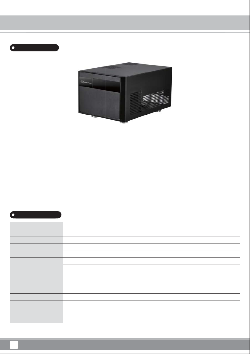
Product Overview
Introduction
oducti
SilverStone’s Sugo series, since its introduction in 2005, has been the de facto standard for which retail
tone’s Sugo series, since its introduction in 2005, has been the de facto standard for whic
small form factor cases are defined. The introduction of SG11 is both a tribute and advancement to one
of the most revered case design within SilverStone product portfolio, the Sugo SG01.
With classic shoebox proportion maintained, the SG11 continues to impress with its ability to
accommodate many standard sized components such as ATX power supply and room for graphics cards
up to 14.5 inches. For cooling, side intake fan size has been upgraded to 120mm from 80mm to help cope
with future hardware demands. For storage, redesigned internal layout allows for installation of up to nine
2.5” drives. Finished with cleanly styled acrylic accent, the beautiful SG11 is a great case for anyone
looking to build a compact workstation or a powerful small form factor gaming system.
or cases are
ost revered case design within SilverStone product portfolio, the Su
vancem
o SG01.
Specification
Material
Model
Motherboard
Drive Bay
Cooling System
Expansion Slot
Front I/O Port
Power Supply
Expansion Card
Limitation of CPU cooler
Dimension
* Fan and drive cage configuration will affect graphics card length support, please refer to manual for detailed information.
1
ABS & Acrylic front panel, steel body
SST-SG11B (black)
Micro ATX, Mini-DTX, Mini-ITX
Exposed
Internal
Top
Side
Rear
4
USB 3.0 x 2, audio x 1, MIC x 1
Optional standard PS2(ATX)
*Support graphics card up to 14.5”, width restriction-4.46"
82mm
270 mm (W) x 212 mm (H) x 393 mm (D), 22.5 liters
5.25” x 1
3.5" x 3 (compatible with 2.5”), 2.5” x 9
1 x 80mm fan slot
1 x 120mm intake fan, 1200rpm
1 x 80mm fan slot, Optional cross-flow fan
Page 5
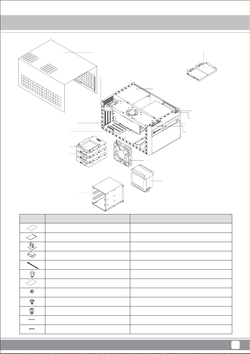
EXPANSION SLOT X 4
MOTHERBOARD (Micro ATX,
Mini-DTX, Mini-ITX) (OPTIONAL)
HDD TRAY X 3
3.5” OR 2.5” HDD X 3
(OPTIONAL)
Sugo Series SG11
Disassemble Chart
2.5" HDD X 2 (OPTIONAL)
TOP COVER
8025 FAN X 2 (OPTIONAL)
ATX / PS2 PSU (OPTION)
POWER BUTTON
RESET BUTTON
5.25” BAY X 1
USB 3.0 * 2 + SPK + MIC
12025 OR 12015 OR 12010 FAN (OPTIONAL)
2.5" HDD X 7 BRACKET
3.5” HDD BRACKET
PICTURE PURPOSE
ITEM
MANUAL
ZIPPER BAG
CABLE TIES
CABLE TIES
BUNCH WIRE TIES
STANDDFF
ZIPPER BAG
SCREW-6-32X5
SCREW-M3 (A)
SCREW-6-32 (B)
CD DOOR SPONGE
CD BUTTON SPONGE
Installation and maintenance guide
Manage Cables
Manage Cables
Cable management
Motherboard standoff
Secure 3.5" HDD
Secure 2.5" SSD/HDD
Secure PSU
2
Page 6
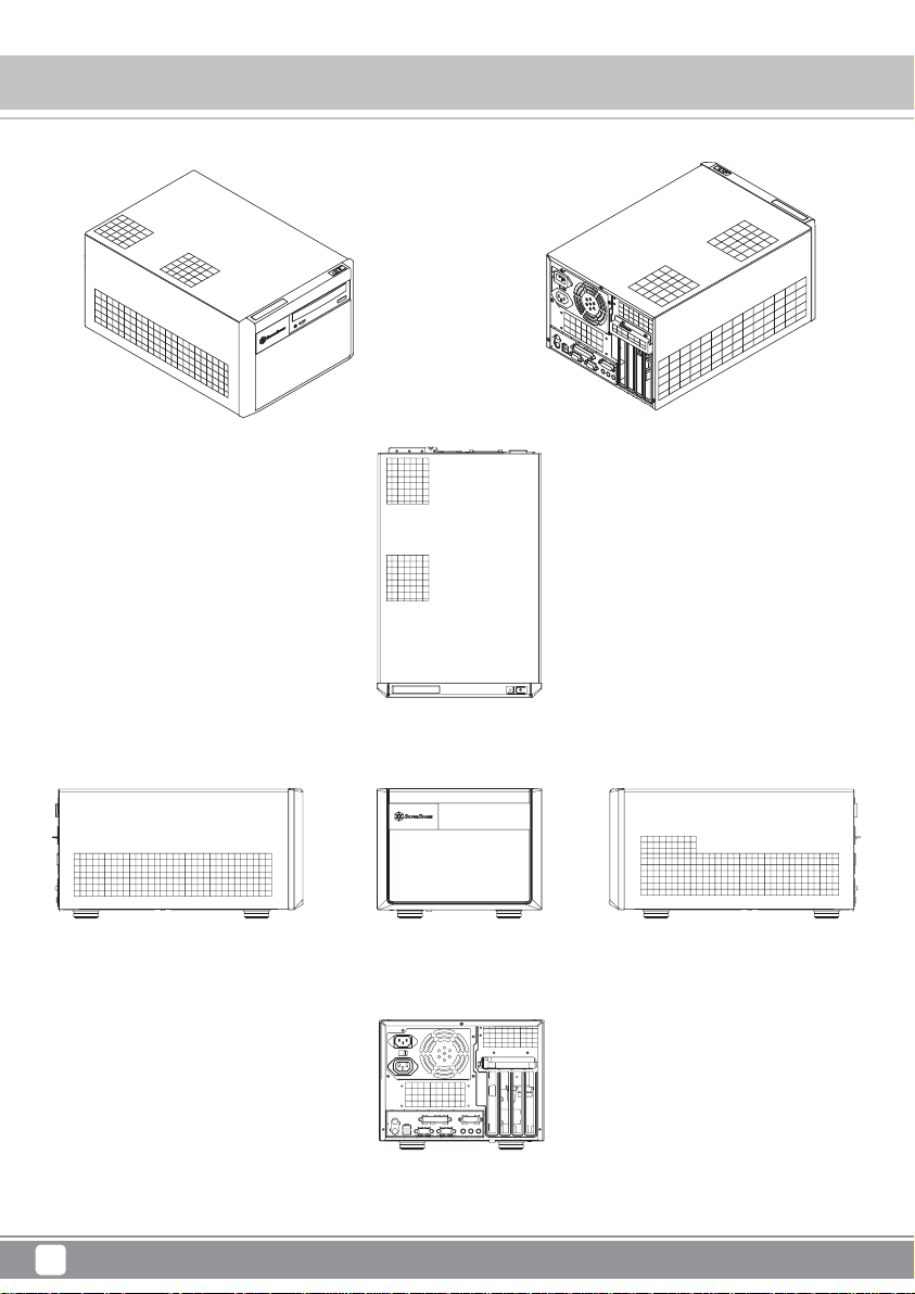
SUGO Series
SG11
Exterior Overview
TOP
FRONT
BACK
3
RIGHT SIDELEFT SIDE
Page 7
Before you begin, please make sure that you
1
have all components collected
2
check that all components do not have compatibility problems with each other or with the case
3
if possible, assemble the components outside the case first to make sure they are working
keep the motherboard manual ready for reference during installation
4
prepare a Philips screwdriver.
5
SUGO Series SG11
Installation Chart
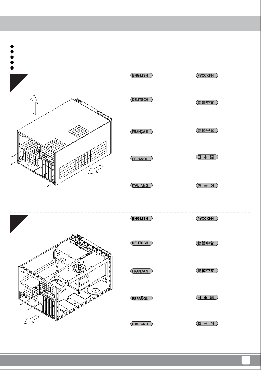
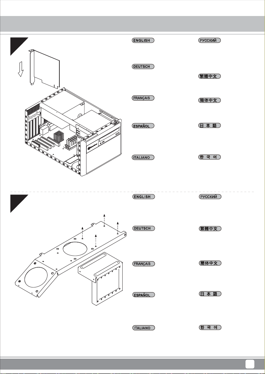
01
02
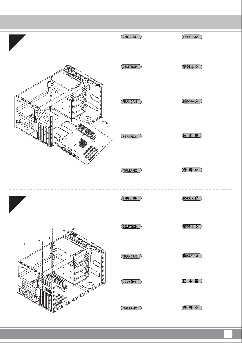
Please remove the screws holding
the top cover with a screw driver,
and then pull it toward back and lift
it outward away from chassis.
Bitte entfernen Sie die Schrauben,
die die obere Abdeckung halten,
mit einem Schraubendreher; ziehen
Sie die Abdeckung dann nach
hinten und nehmen Sie sie nach
außen vom Gehäuse ab.
Veuillez retirer les vis qui retiennent
le couvercle supérieur avec un
tournevis, puis le tirer vers l'arrière
et le soulever vers l'extérieur du
châssis.
Por favor, quite los tornillos que
sujetan la cubierta superior con un
destornillador y luego tire hacia
atrás y levántela apartándola del
chasis.
Utilizzando un cacciavite, rimuovere
le viti che fissano il coperchio
superiore, quindi tirarlo indietro e
sollevarlo allontanandolo dal telaio.
Please remove the screws holding
the expansion card slot cover, and
remove it.
Bitte entfernen Sie die Schrauben,
die die Abdeckung des
Erweiterungskartensteckplatzes
halten; nehmen Sie die Abdeckung
ab.
С помощью отвертки удалите
винты, крепящие верхнюю
крышку, а затем потяните ее
назад и, подняв в направлении
наружу, снимите с корпуса.
請以螺絲起子卸下鎖固上蓋的螺絲,
向後拉並提起自機箱中取出。
请以螺丝起子卸下锁固上盖的螺丝,
向后拉并提起自机箱中取出。
上面カバーを固定しているネジを
ドライバーで外し、後方に引き上
げてケースから取り外します。
스크루드라이버를 사용하여 상부
커버를 고정하는 나사를 푼 후 커
버를 뒤쪽으로 당기고 바깥쪽으로
들어올려 섀시에서 분리합니다.
Выверните винты, крепящие
крышку слота платы
расширения, и снимите ее.
請卸下鎖固擴充卡槽檔板螺絲
並卸下檔板。
Veuillez retirer les vis retenant le
cache de l'emplacement pour carte
d'extension, puis enlever celui-ci.
Quite los tornillos que sujetan la
cubierta de la tarjeta de expansión
y retírela.
Rimuovere le viti che fissano il
coperchio dell'alloggio della scheda
di espansione, e rimuoverlo.
请卸下锁固扩充卡槽档板螺丝
并卸下档板。
拡張カードスロットカバーを固定
しているネジを外し、カバーを取
り外します。
확장 카드 슬롯 커버를 고정하는
나사를 풀어 커버를 분리합니다.
4
Page 8
SUGO Series SG11
Installation Chart
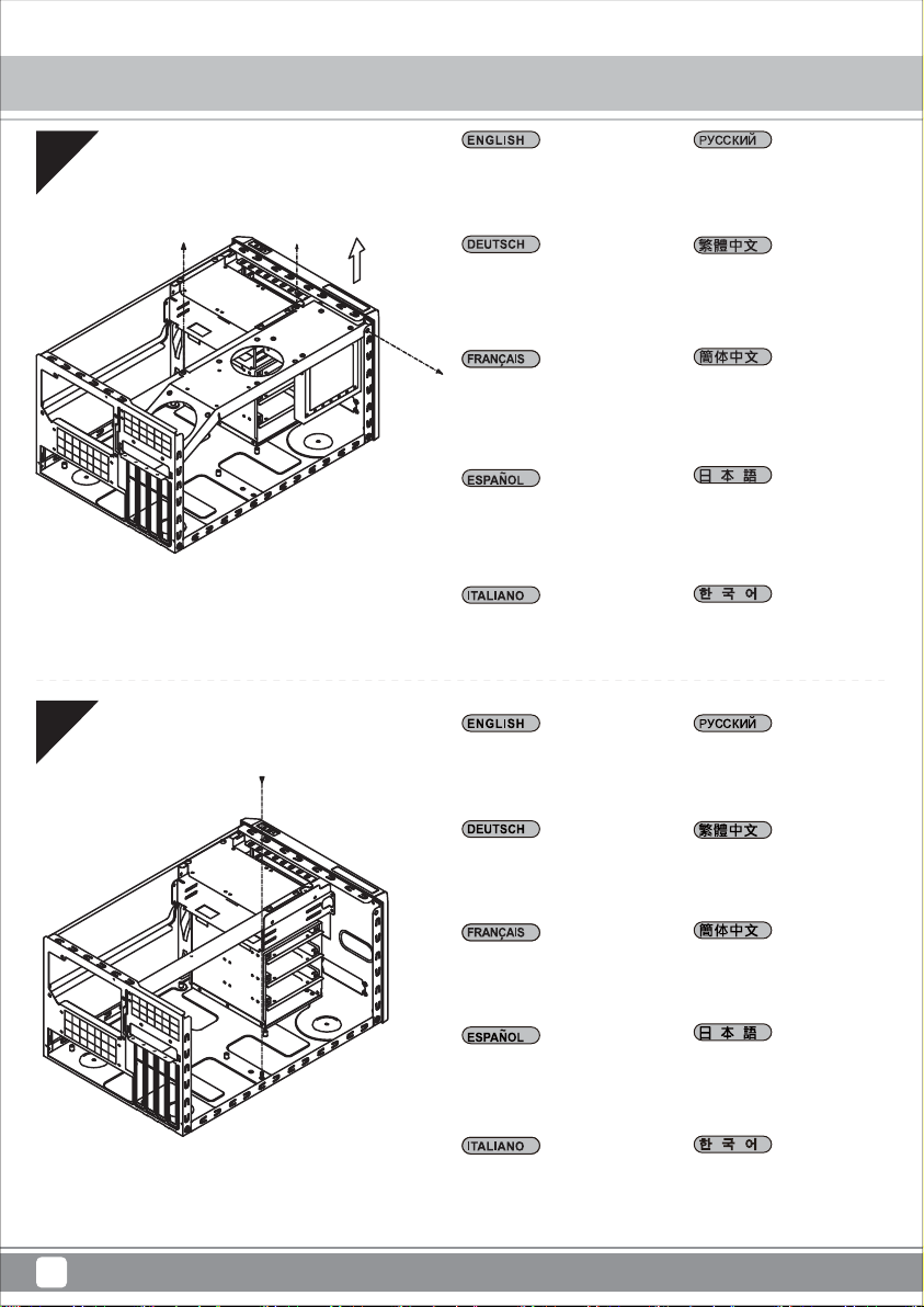
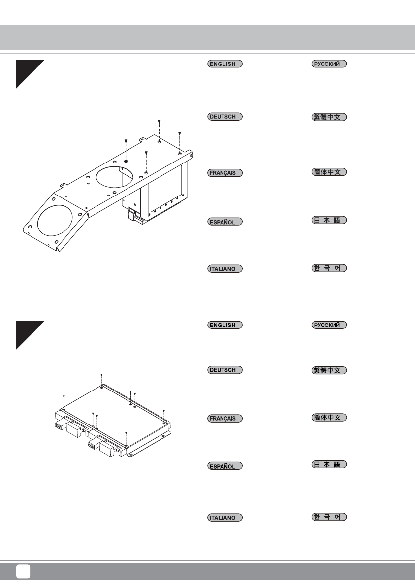
03
04
Please remove the screws on the fan
bracket, and then remove the bracket
outward from chassis.
Bitte entfernen Sie die Schrauben an
der Lüfterhalterung und nehmen Sie
die Halterung dann aus dem Gehäuse.
Retirez les vis du support de ventilateur,
puis retirez le support vers l'extérieur du
châssis.
Quite los tornillos del bracket para
ventilador y luego saque el bracket del
chasis.
Rimuovere le viti sul supporto ventola,
quindi allontanare il supporto dal telaio.
Fasten and secure the standoffs
as required.
Выверните винты из кронштейна
вентилятора, а затем снимите
кронштейн с корпуса в
направлении наружу.
請卸下風扇架上螺絲,並自機箱
取出風扇架。
请卸下风扇架上螺丝,并自机箱
取出风扇架。
ファンブラケットのネジを外し、
ブラケットをケース外側へ外し
ます。
팬 브래킷의 나사를 푼 후 브래킷을
바깥쪽으로 당겨 섀시에서 분리합니
다.
Затяните и закрепите опорные
стойки по месту.
Befestigen und sichern Sie die
Abstandhalter wie erforderlich.
Serrez et fixez les entretoises
comme requis.
Fije y asegure los soportes
según sea necesario.
Stringere e fissare i distanziatori
come richiesto.
請依照需求鎖固主機板螺柱。
请依照需求锁固主板螺柱。
スペーサーを必要に応じて固定し
ます。
필요한 경우 스탠드 오프를 조이고
고정합니다.
5
Page 9
SUGO Series SG11
Installation Chart
05
06
Please install your motherboard into
the chassis as shown.
Bitte installieren Sie Ihr Motherboard
wie abgebildet im Gehäuse.
Installez votre carte mère dans le
châssis comme illustré.
Por favor, instale su placa base en el
chasis como se muestra.
Installare la scheda madre nel telaio
come mostrato.
Please secure your motherboard with
included screws (screw A).
Установите системную плату в
корпус, как показано на
рисунке.
請依圖示安裝您的主機板。
请依图示安装您的主板。
図のようにマザーボードをケースに
取り付けます。
그림과 같이 마더보드를 섀시에 설치
합니다.
Зафиксируйте материнскую
плату с помощью винтов из
комплекта (винт A).
Bitte befestigen Sie Ihr Motherboard
mit den mitgelieferten Schrauben
(Schraube A).
Fixez votre carte mère avec les vis
fournies (vis A).
Por favor, asegure su placa base con
los tornillos incluidos (tornillo A).
Fissare la scheda madre utilizzando
le viti fornite in dotazione (viti A).
請以內附螺絲(螺絲A)鎖固您的主
機板。
请以内附螺丝(螺丝A)锁固您的主
板。
マザーボードは、付属のネジ(ネジA)
で固定します。
제공된 나사(나사 A)를 사용하여 마더
보드를 고정합니다.
6
Page 10
SUGO Series SG11
Installation Chart
07
08
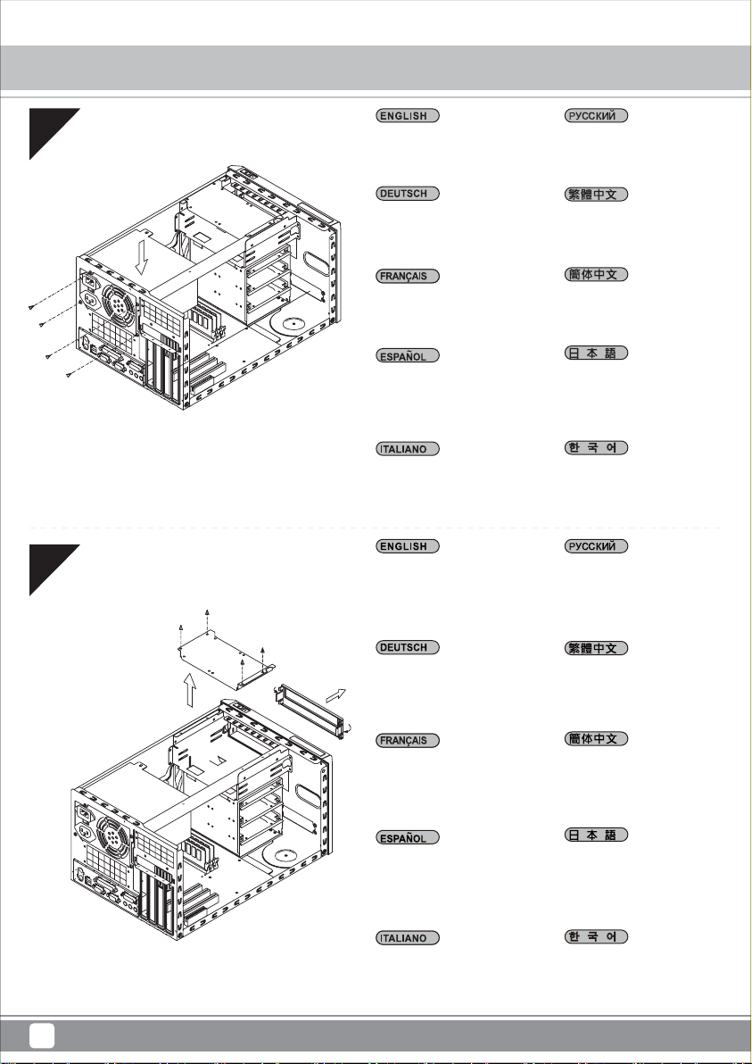
Insert your power supply from the top
as shown and secure it with included
screws (screws B).
Setzen Sie Ihr Netzteil wie abgebildet
von oben ein und befestigen Sie es
mit den mitgelieferten Schrauben
(Schraube B).
Insérez votre alimentation depuis le
dessus comme illustré et fixez-la avec
les vis fournies (vis B).
Inserte su fuente de alimentación desde
la parte superior como se muestra y
asegúrela con los tornillos incluidos
(tornillos B)
Inserire l'alimentatore dalla parte
superiore, come mostrato, e fissarlo
utilizzando le viti fornite in dotazione
(viti B).
Please remove 2.5” hard drive
bracket and press the area as
shown to release 5.25” device
bay cover.
Вставьте блок питания сверху,
как показано на рисунке, и
закрепите его с помощью
прилагающихся винтов (винты B).
請依圖示自上方安裝您的電源供應
器,並以內附螺絲鎖固(螺絲B)。
请依图示自上方安装您的电源供应
器,并以内附螺丝锁固(螺丝B)。
図のように電源を上面から入れて、
付属のネジ(ネジB)で固定します。
그림과 같이 위로부터 전원 공급장치를
삽입하고, 제공된 나사(나사 B)를
사용하여 이를 고정합니다.
Снимите кронштейн
2,5-дюймового жесткого диска
и нажмите на область, как
показано на рисунке, чтобы
освободить крышку отсека
5,25-дюймового устройства.
Bitte entfernen Sie die 2,5-ZollFestplattenhalterung und drücken
Sie den abgebildeten Bereich zur
Freigabe der Abdeckung des
5,25-Zoll-Geräteschachts.
Retirez le support de disque dur
2,5" et appuyez sur la zone
comme illustré pour dégager le
cache de la baie de périphérique
5,25".
Por favor, retire el bracket para
discos duros de 2,5” y presione la
zona como se muestra para
liberar la cubierta de la bahía de
dispositivos de 5,25”.
Rimuovere il supporto disco rigido
2,5” e premere l'area mostrata per
sbloccare il coperchio dell’alloggio
unità 5,25”.
請先取下2.5吋硬碟架,再輕壓圖
示區域以卸下5.25吋裝置檔板。
请先取下2.5吋硬盘架,再轻压图
标区域以卸下5.25吋装置文件板。
2.5”ハードディスクドライブブラ
ケットを外し、図に示される部分
を押して5.25”デバイスベイのカ
バーを開放します。
2.5” 하드 드라이브 브래킷을 풀고
그림에 표시된 부분을 눌러 5.25”
장치 베이 커버를 분리합니다.
7
Page 11
SUGO Series SG11
Installation Chart
09
10
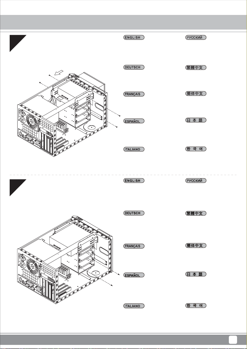
Insert your optical drives through the
front as shown and secure ith
included screws (screws A).
Setzen Sie Ihre optischen Laufwerke
wie abgebildet von vorne ein und
sichern Sie sie mit den mitgelieferten Schrauben (Schraube A).
Insérez vos lecteurs optiques par
l'avant comme illustré, et fixez-les
avec les vis fournies (vis A).
Inserte su dispositivo óptico a través
del frontal como se muestra y fíjelo
con los tornillos incluidos (tornillos A).
Inserire le unità ottiche dalla parte
anteriore, come mostrato, e fissare
utilizzando le viti fornite in dotazione
(viti A).
Remove the screws holding the hard
drive tray, and then remove the tray
outward from chassis.
Вставьте приводы оптических
дисков с передней стороны, как
показано на рисунке, и
закрепите их с помощью
винтов из комплекта (винты A).
請依圖示自前方安裝您的光碟裝
置,並以內附螺絲鎖固(螺絲A)。
请依图标自前方安装您的光盘装
置,并以内附螺丝锁固(螺丝A)。
図のように光学ドライブをフロント
から入れ、付属のネジ(ネジA)で固定
します。
그림과 같이 전면을 통해 광 드라이브
를 삽입하고 제공된 나사(나사 A)를
사용하여 이를 고정합니다.
Удалите винты, крепящие
лоток для жесткого диска, и
затем извлеките лоток из
корпуса.
Entfernen Sie die Schrauben, die den
Festplatteneinschub halten; nehmen
Sie dann den Einschub aus dem
Gehäuse.
Enlevez les vis qui retiennent le
plateau de disque dur, puis retirez le
plateau vers l'extérieur du châssis.
Retire los tornillos que sujetan la
bandeja para discos duros y luego
saque la bandeja del chasis.
Rimuovere le viti che fissano il
cassetto del disco rigido, quindi
allontanare il cassetto dal telaio.
請先卸下鎖固硬碟托盤螺絲,再
將其自機箱中取出。
请先卸下锁固硬盘托盘螺丝,再
将其自机箱中取出。
ハードディスクドライブトレイを固
定しているネジを外し、トレイをケ
ース外側へ外します。
하드 드라이브 트레이를 고정하는 나
사를 푼 후 트레이를 바깥쪽으로 당겨
섀시에서 분리합니다.
8
Page 12
SUGO Series SG11
Installation Chart
11
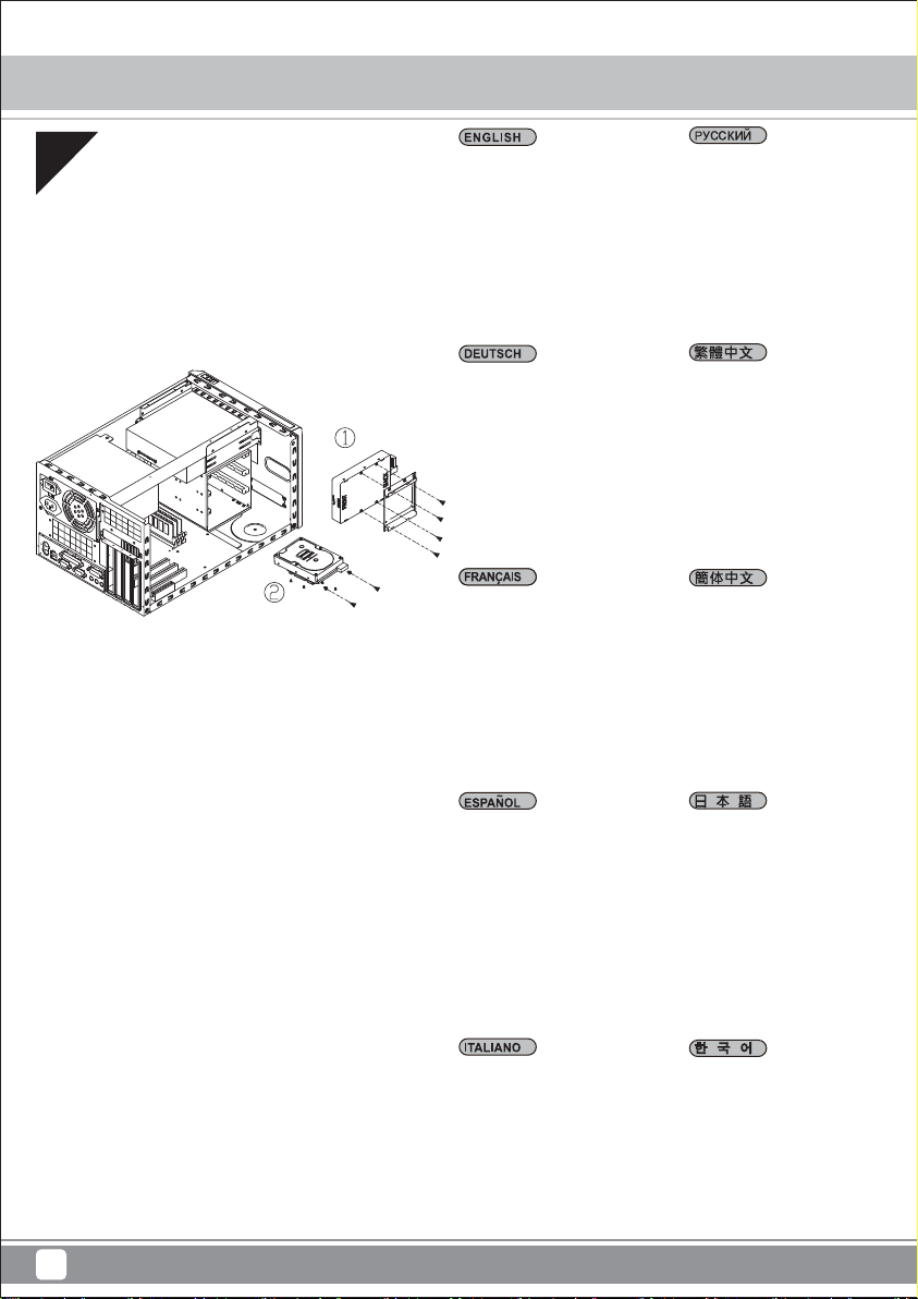
Place your hard drive on the tray and
secure with included screws (screws
B). Then insert your hard drive with
the tray into the chassis and secure
with screws (step 10). Caution: the
secure with mount of hard drive tray
should be place at the same side with
your hard drive connector jack.
Positionieren Sie Ihre Festplatte am
Einschub und sichern Sie sie mit den
mitgelieferten Schrauben (Schraube
B). Setzen Sie Ihre Festplatte dann
mit dem Einschub im Gehäuse ein
und sichern Sie sie mit Schrauben
(Schritt 10). Achtung: Die
Befestigung des Festplatteneinschubs sollte auf der Seite erfolgen,
auf der sich auch der Festplattenanschluss befindet.
Placez votre disque dur sur le plateau
et fixez-le avec les vis fournies (vis B).
Puis insérez votre disque dur avec le
plateau dans le châssis et fixez-le avec
des vis (étape 10). Attention : le support
du plateau de disque dur doit être du
même côté que la prise du connecteur
de disque dur.
Поместите жесткий диск в лоток
и закрепите его винтами из
комплекта (винты B). Затем
вставьте лоток с жестким диском
в корпус и зафиксируйте его с
помощью винтов (шаг 10).
Внимание! Крепление лотка
выполняется с той же стороны,
где расположен соединительный
разъем для жесткого диска.
請將您的硬碟安裝置硬碟托盤中,
並以內附螺絲(螺絲B)鎖固後,安
裝回機箱內,再以步驟10卸下的螺
絲鎖固。請注意鎖固硬碟托盤的方
向必須與硬碟連接線接頭一致。
请将您的硬盘安装置硬盘托盘中,
并以内附螺丝(螺丝B)锁固后,安
装回机箱内,再以步骤10卸下的螺
丝锁固。请注意锁固硬盘托盘的方
向必须与硬盘连接线接头一致。
Coloque su disco duro en la bandeja y
fíjelo con los tornillos incluidos (tornillos
B). Luego inserte su disco duro con la
bandeja en el chasis y fíjelo con los
tornillos (paso 10). Aviso: el disco duro
montado en la bandeja debería situarse
en el mismo lado de su conector para
disco duro.
Collocare il disco rigido nel cassetto e
fissarlo utilizzando le viti fornite in
dotazione (viti B). Quindi inserire nel
telaio il cassetto con il disco rigido e
fissare con le viti (punto 10). Attenzione:
la parte con le prese del cassetto
contenente il disco rigido deve essere
collocata sullo stesso lato del
connettore del disco rigido.
ハードディスクをトレイに置き、
付属のネジ(ネジB)で固定します。
それからハードディスクを装着し
たトレイをケースに収めてネジで
固定します(ステップ10)。注意:
ハードディスクドライブトレイは、
ハードディスクコネクタジャック
と同じ向きに設置してください。
하드 드라이브를 트레이에 올려 놓고 제
공된 나사(나사 B)를 사용하여 고정합니
다. 그리고 트레이가 장착된 하드 드라이
브를 섀시에 삽입하고 나사를 사용하여
고정합니다(10 단계). 주의: 하드 드라이브
트레이는 하드 드라이브 커넥터 잭과 동
일한 면에 놓고 장착해야 합니다.
9
Page 13
SUGO Series SG11
Installation Chart
12
13
Install graphic card or expansion
card. (If an extension expansion
card installation is needed, please
refer to the installation guide of it.)
Installieren Sie eine Grafik- oder
Erweiterungskarte. (Falls eine
Erweiterungskarte installiert werden
muss, beachten Sie bitte die
zugehörige Installationsanleitung.)
Installez la carte graphique ou
d'extension. (S'il est nécessaire
d'installer une carte d'extension,
consultez son guide d'installation.)
Instale la tarjeta gráfica o tarjeta
de expansión. (Si es necesario
instalar una tarjeta de expansión,
por favor consulte su guía de
instalación).
Installare la scheda video o la scheda
di espansione. (Se è necessaria
l’installazione di una scheda di
espansione, fare riferimento alla
guida all’installazione della scheda
stessa.)
Remove 2.5” drive bracket from the
fan bracket.
Установите графическую карту
или плату расширения. (Если
необходимо установить
дополнительную плату
расширения, воспользуйтесь
руководством по ее установке.)
安裝顯示卡或擴充卡(如需安裝超
長擴充卡,請參考內附擴充卡安裝
指南)。
安装显卡或扩充卡(如需安装超长
扩充卡,请参考内附扩充卡安装
指南)。
グラフィックスカードまたは拡張
カードをインストールします。
(拡張カードのインストールが必
要な場合は、そのカードのインス
トールガイドをご参照ください。)
그래픽 카드 또는 확장 카드를 설치
합니다. (확장 카드를 설치해야 할
경우, 카드의 설치 설명서를 참조하
십시오.)
Снимите кронштейн для
2,5-дюймового жесткого диска
с кронштейна вентилятора.
Entfernen Sie die 2,5-ZollLaufwerkshalterung von der
Lüfterhalterung.
Retirez le support de lecteur 2,5" du
support de ventilateur.
Retire el bracket para dispositivos de
2,5” del bracket para ventilador
Rimuovere il supporto unità da 2,5”
dal supporto ventola.
請將2.5吋硬碟架自風扇架上拆下。
请将2.5吋硬盘架自风扇架上拆下。
2.5”ドライブブラケットをファン
ブラケットから外します。
팬 브래킷에서 2.5” 드라이브 브래킷
을 분리합니다.
10
Page 14
SUGO Series SG11
Installation Chart
14
15
Secure 2.5” drive to bracket with
included screws (screw B), then
reinstall drive bracket back onto fan
bracket.
Befestigen Sie das 2,5-Zoll-Laufwerk
mit den mitgelieferten Schrauben
(Schraube B) an der Halterung;
installieren Sie die Laufwerkshalterung dann wieder an der Lüfterhalterung.
Fixez le lecteur 2,5" avec les vis
fournies (vis B), puis réinstallez le
support de lecteur sur le support de
ventilateur.
Fije el dispositivo de 2,5” al bracket con
los tornillos incluidos (tornillo B), luego
vuela a reinstalar el bracket para
dispositivo en el bracket para ventilador.
Fissare l’unità da 2,5” al supporto
utilizzando le viti fornite in dotazione (viti
B), quindi reinstallare il supporto unità
sul supporto ventola.
Secure 2.5” drive to bracket
removed from step 8 with
included screws (screw B)
Прикрепите 2,5-дюймовый диск к
кронштейну винтами из
комплекта (винт В) и установите
кронштейн диска обратно на
кронштейн вентилятора.
將2.5吋硬碟用內附螺絲(螺絲B)鎖
固在硬碟架上,再以步驟13卸下的
螺絲將硬碟架鎖固在風扇架上。
将2.5吋硬盘用内附螺丝(螺丝B)锁
固在硬盘架上,再以步骤13卸下的
螺丝将硬盘架锁固在风扇架上。
2.5”ドライブをブラケットに付属
のネジ(ネジB)で固定してから、ド
ライブブラケットをファンブラケ
ットに戻します。
제공된 나사(나사 B)를 사용하여 2.5” 드라
이브를 브래킷에 고정한 후, 드라이브 브
래킷을 팬 브래킷에 도로 설치합니다.
Закрепите 2,5-дюймовый диск
на кронштейне, снятом на шаге
8, с помощью винтов из
комплекта (винт В).
Befestigen Sie das 2,5-ZollLaufwerk mit den mitgelieferten
Schrauben (Schraube B) an der in
Schritt 8 entfernten Halterung.
Fixez le lecteur de 2,5" sur le
support retiré à l'étape 8 avec les
vis fournies (vis B).
Fije el dispositivo de 2,5” al
bracket que se retiró en el paso 8
con los tornillos incluidos (tornillo
B).
Fissare l’unità da 2,5” al supporto
rimosso dal punto 8 utilizzando le
viti fornite in dotazione (viti B).
將2.5吋硬碟用內附螺絲(螺絲B)
鎖在從步驟8取下的硬碟架上。
将2.5吋硬盘用内附螺丝(螺丝B)
锁在从步骤8取下的硬盘架上。
2.5”ドライブをステップ8で外し
たブラケットに、付属のネジ(ネジ
B)で固定します。
2.5” 하드 드라이브 브래킷을 풀고
그림에 표시된 부분을 눌러 5.25”
장치 베이 커버를 분리합니다.
11
Page 15

SUGO Series SG11
Installation Chart
16
17
Reinstall bracket from step 8 back
onto the case.
Installieren Sie die Halterung aus
Schritt 8 dann wieder am Gehäuse.
Réinstallez le support de l'étape 8
dans le boîtier.
Reinstale el bracket del paso 8 de
nuevo en la carcasa.
Reinstallare sul telaio il supporto
partendo dal punto 8.
Reinstall the fan bracket into chassis
and secure with screw. (One or two
optional 80mm fans can be installed
onto the fan bracket.)
Установите кронштейн, снятый
на шаге 8, обратно в корпус.
再以步驟8卸下的螺絲將硬碟架
鎖固在支架上。
再以步骤8卸下的螺丝将硬盘架锁
在支架上。
ステップ8でのブラケットをケース
に戻します。
8 단계에서 분리한 브래킷을 케이
스에 도로 설치합니다.
Установите кронштейн
вентилятора на место в корпус
и закрепите винтом. (На
кронштейн вентилятора можно
установить один или два
дополнительных вентилятора
с типоразмером 80 мм.)
Bringen Sie die Lüfterhalterung
wieder im Gehäuse an und sichern
Sie sie mit Schrauben. (Ein oder zwei
optionale 80-mm-Lüfter können an
der Lüfterhalterung installiert werden.)
Réinstallez le support de ventilateur
dans le châssis et fixez-le avec des
vis. (Un ou deux ventilateurs
optionnels de 80 mm peuvent être
installés sur le support de ventilateur.)
Reinstale el bracket para ventilador
en el chasis y asegúrelo con tornillos
(Se pueden instalar uno o dos
ventiladores opcionales de 80mm en
el bracket para ventilador).
cReinstallare sul telaio la staffa della
ventola, quindi fissarla con le viti.
(Sulla staffa della ventola possono
essere installate una o due ventole
opzionali da 80 mm.)
請將風扇架裝回機箱並以螺絲鎖固
(可選配一個或兩個80mm的風扇)。
请将风扇架装回机箱并以螺丝锁固
(可选配一个或两个80mm的风扇)。
ファンブラケットをケースに戻し、
ネジで固定します。(ファンブラケ
ットにはオプションの80mmファン
1~2台が装着可能です。)
팬 브래킷을 섀시에 도로 설치하고 나
사를 사용하여 고정합니다. (옵션인
80mm 팬 1개 또는 2개를 팬 브래킷에
설치할 수 있습니다.)
12
Page 16

SUGO Series SG11
Installation Chart
18
19
Reinstall the expansion card slot
cover and secure with screws.
Bringen Sie die Abdeckung des
Erweiterungskartensteckplatzes
wieder an und befestigen Sie sie mit
Schrauben.
Reinstale la cubierta del zócalo de la
tarjeta de expansión y fíjela con tornillos
Réinstallez le cache de l'emplacement
de la carte d'extension et fixez-le avec
des vis.
Reinstallare il coperchio dell'alloggio
della scheda di espansione e fissarlo
con le viti.
After all cables and wirings are
connected, reinstall the top
cover and secure it.
Установите крышку слота платы
расширения обратно на место и
закрепите ее винтами.
請裝回擴充卡槽檔板並以螺絲鎖固。
请装回扩充卡槽档板并以螺丝锁固。
拡張カードスロットカバーを戻し、
ネジで固定します。
확장 카드 슬롯 커버를 도로 설치하고 나
사를 사용하여 고정합니다.
После подключения всех
кабелей и проводов установите
на свое место верхнюю крышку
и закрепите ее.
Nachdem alle Kabel und Drähte
angeschlossen wurden, bringen Sie
die obere Abdeckung wieder an und
befestigen sie.
Une fois tous les câbles et fils
connectés, replacez le couvercle
supérieur et fixez-le.
Después de conectar todo el
cableado, reinstale la cubierta
superior y fíjela.
Dopo avere collegato tutti i cavi ed
i cablaggi, reinstallare il coperchio
superiore e fissarlo.
請確認所有必需的線材與線路都已
連接後,將上蓋裝回機箱並以螺絲
鎖固。
请确认所有必需的线材与线路都已
连接后,将上盖装回机箱并以螺丝
锁固。
ケーブルおよび結線の接続を確認
後、上面カバーを戻して固定しま
す。
모든 케이블과 배선이 연결되면,
상부 커버를 도로 설치하고 고정합
니다.
13
Page 17

SUGO Series SG11
Installation Chart
20
Installation complete. Установка завершена.
Damit ist die Installation
abgeschlossen.
L'installation est terminée.
安裝完成。
安装完成。
Instalación completa.
L'installazione è completata.
インストール完了。
설치가 완료되었습니다.
14
Page 18

SUGO Series SG11
Connector Definition
(1) Front Panel Connectors
A.Power switch and reset switch installation guide:
Please refer to the motherboard manuals for the motherboard’s “Front Panel Connector” or “System Panel Connector” pin definitio
Power switch and reset switch have no polarity, so they can be connected in any orientation.
Bitte suchen Sie in der Motherboard-Dokumentation nach der Pinbelegung der Anschlüsse des Frontbedienfeldes („Front Panel Conne
oder „ System Panel Connectors“). Ein-/Austaste und Rücksetztaste benötigen keine bestimmte Polarität, können daher beliebig (o
und - zu achten) angeschlossen werden.
Veuillez-vous référer au manuel de votre carte mère pour la description des broches "des connecteurs du panneau frontal" et des
"des connecteurs du panneau système". Les interrupteurs d'allumage et de réinitialisation ne possède pas de polarité, donc ils peuvent être
branché dans les deux sens.
Por favor, consulte en los manuales de la placa base la configuración de pines del “Conector de panel frontal” ó “Conector de panel de sistema”
de su placa base. Los interruptores de encendido y reseteo no tienen polaridad, luego se pueden conectar con cualquier orientac
Fare riferimento al manuale della scheda madre nella sezione “Connettori del pannello frontale” o “Connettori del pannello di sistema”. Power
switch e reset switch non hanno polarità, posso essere pertanto connessi con qualsiasi orientamento.
Описание контактов разъемов приведены в разделах “Разъемы передней панели” или “Разъемы системной панели” руководства
пользователя материнской платы. Вык лючатель питания и кнопка перезагрузки не имеют полярности, поэтому их можно подключать
в любой ориентации.
請參考主機說明書的Front Panel Connectors安裝Pin Define,將Connector插上;Power Switch 與Reset Switch並無正負極性之分,
反插正插都不影響功能性。
请参考主机说明书的Front Panel Connectors安装Pin Define,将Connector插上;Power Switch 与Reset Switch
反插正插都不影响功能性。
マザーボードの「フロントパネルコネクタ」または「システムパネルコネクタ」のピン配列についてはマザーボードマニュアルを参照してください。
電源スイッチとリセットスイッチに極性はないので、いずれの方向でも接続できま。
메인보드 매뉴얼의 전면패널 커넥터 혹은 시스템패널 커넥터 핀을 참조하기 바랍니다. 파워 스위치와 리셋 스위치는 극 성이 없어 어떤
방향으로 설치해도 무방합니다.
并无正负极性之分,
15
Page 19

SUGO Series SG11
Connector Definition
(1) Front Panel Connectors
B:LED indicators installation guide
Please refer to the motherboard manuals for the motherboard’s “Front Panel Connector ” or “System Panel Connector” pin definition.; the white/black
wires are negative while other colors are positive wires. The Power LED wires are separate pins for compatibility with different motherboard pin
definition so please make sure they are connected in the right polarity by referring to your motherboard manual.
Bitte suchen Sie in der Motherboard-Dokumentation nach der Pinbelegung der Anschlüsse des Frontbedienfeldes („Front Panel Connectors“ oder „
System Panel Connectors“). Die weißen/ schwarz Adern sind negativ (-), die farbigen Adern positiv (+).Die Kabel für die Betriebsanzeige-LED sind
zur Kompatibilität mit unterschiedlichsten Motherboards einzeln, nicht als kompletter Stecker ausgeführt. Achten Sie hier bitte auf die richtige
Polarität, lesen Sie in der Dokumentation Ihres Motherboards nach.
Veuillez-vous référer au manuel de votre carte mère pour la description des broches "des connecteurs du panneau frontal" et des broches "des connecteurs du panneau
système". Les câbles colorés en blanc/noir sont négatifs alors que ceux d'une autre couleur sont positifs. Les câbles de la LED Power sont séparés afin d'être compatible
avec différentes cartes mères, donc vérifiez bien qu'ils sont branchés avec la bonne polarité en vous référant au manuel de votre carte mère
Por favor, consulte en los manuales de la placa base la configuración de pines del “Conector de panel frontal” ó “Conector de panel de sistema” de
su placa base. Los cables de color blanco/negro son negativos mientras que los de color son positivos. Los cables LED de potencia tienen pines
separados para compatibilidad con diferentes definiciones de pines de la placa base luego por favor, asegúrese de que están conectados en la
polaridad correcta consultando el manual de su placa base.
Fare riferimento al manuale della scheda madre nella sezione “Connettori del pannello frontale” o “Connettori del pannello di sistema”. I cavi di
colore bianco/nero sono il polo negativo, mentre quelli di colore diverso il positivo.
Описание контактов разъемов приведены в разделах “Разъемы передней панели” или “Разъемы системной панели” руководства
пользователя материнской платы. Белые/черный провода - отрицательной полярности, цветные провода - положительной полярности.
Провода светодиодного индикатора питания имеют отдельные контакты для совместимости с различными типами контактов материнских
плат, поэтому обратитесь к руководству пользователя материнской платы и убедитесь, что полярность соблюдена.
請參考主機說明書的Front Panel Connectors安裝Pin Define,將Connector插上;白/黑色線的部分為負極,彩色線的部分是正極。
Power LED為了適應各主機板的不同, 特別設計為散Pin樣式,請安心使用。
请参考说明书的Front Panel Connectors安装Pin Define,将Connector插上;白/黑色线的部份为负极,彩色线的部份为正极。
Power LED为了适应主机板的不同, 特别设计为散Pin样式,请安心使用。
マザーボードの「フロントパネルコネクタ」または「システムパネルコネクタ」ピン配列についてはマザーボードマニュアルを参照してください。
白/黑色のリード線はマイナスで、色の着いたリード線がプラスです。電源LEDリード線は種々のマザーボードピン定義と互換性を持たせるため分離されたピ
ンとなっているので、ご使用のマザーボードマニュアルを参照して、適切な極性に接続されるようお確かめください。
메인보드 매뉴얼의 전면패널 커넥터 혹은 시스템패널 커넥터 핀을 참조하기 바랍니다. 하얀/검은선의 경우 음극이며, 다른 색의 경우
양극입니다. 파워 LED 선은 분리되어 다양한 메인보드에서 동작할 수 있도록 되어 있습니다. 그러므로 메인보드 매뉴얼을 참조하여 올바를
극성을 주의해 선택하시기 바랍니다.
16
Page 20

SUGO Series SG11
Connector Definition
(2) Front I/O connector guide
Below are the front I/O connectors pin definition, please also check your motherboard manual to cross reference with motherboard’s
front I/O pin headers. SilverStone’s I/O connectors are in block type to simplify installation.
Nachstehend finden Sie die Pinbelegung der vorderen E/A-Anschlüsse; bitte gleichen Sie zudem das Handbuch Ihres Motherboards mit
den vorderen E/A-Pinzuweisungen ab. SilverStones E/A-Anschlüsse befinden sich zur Vereinfachung der Installation in Blockart.
Au dessous de la description des broches des ports d'E/S, veuillez aussi vérifier sur le manuel de votre carte mère de manière croisée
que les broches sont correctement placées. Les connecteurs d'E/S de SilverStone sont en bloc pour en simplifier leur installation.
A continuación tiene la definición de pines de los conectores frontales de E/S, también debe consultar el manual de su placa base para c
omprobar la referencia de los pines para E/S frontales. Los conectores de E/S de SilverStone son de bloque para simplificar la instalación.
Di seguito lo schema delle connessioni I/O frontali, confrontare lo schema con quanto riportato sul manuale della scheda madre per
effettuare una controllo incrociato. I connettori I/O Silverstone, per semplificare l’installazione, sono del tipo “a blocco”.
Ниже приведено описание контактов передних разъемов ввода/вывода. Обратитесь также к руководству пользователя материнской
платы за описанием передних разъемов ввода/вывода типа "пин-хедер". Разъемы ввода/вывода "SilverStone" - блочного типа, что
облегчает сборку.
下表為Front I/O Connectors的Pin Define,請參閱主機板說明書的各Front I/O Connectors Pin Define一一核對。
Front I/O Connectors完全採用集合Pin方式以簡化安裝。
下表为Front I/O Connectors的Pin Define,请参阅主机板说明书的各Front I/O Connectors Pin Define一一核对。
Front I/O Connectors完全采用集合Pin方式以简化安装。
以下はフロントI/Oコネクタピン配列ですが、お持ちのマザーボードのフロントI/Oピンヘッダは、マザーボードマニュアルをご参照ください。
シルバーストーンのI/Oコネクタは、インストールの容易なブロックタイプになっています。
아래는 전면 I/O 커넥터의 핀 설정이며, 메인보드 매뉴얼을 참조해 메인보드의 전면 I/O 핀 헤더와 맞추어 설치합니다.
Silverstone의 I/O 커낵터는 블록 타이브로 구성되어 설치를 간편화 했습니다.
USB 3.0 CONNECTOR HD CONNECTOR
Pin 1
Vbus
IntA_P1_SSRX-
IntA_P1_SSRX+
GND
IntA_P1_SSTX-
IntA_P1_SSTX+
GND
IntA_P1_D-
IntA_P1_D+
ID
Pin 19
Vbus
IntA_P2_SSRXIntA_P2_SSRX+
GND
IntA_P2_SSTXIntA_P2_SSTX+
GND
IntA_P2_DIntA_P2_D+
AUD GND
PRESENCE
SENSE1_RETURN
PIN
SENSE2_RETURN
PORT1L
PORT1R
PORT2R
SENSE_SEND
PORT2L
Pin 11Pin 10
17
Pin
Page 21

SUGO Series SG11
Component Size Limitations
The SG11 can accommodate all standard size components and even some that are out of spec, please refer to the following guidelines for
component selection and future upgrade considerations
(1) CPU Cooler limitation
A. CPU cooler height limitation:The SG11 has 82mm height limitation for CPU cooler.
B. Upper boundary:The cooler can protrude 10mm over the motherboard edge
C. Front boundary:Cooler can protrude from motherboard edge by 3mm.
D. Rear boundary: If optional crossflow fan is installed in the rear of the case, then there is 45mm less room from the edge of motherboard.
If no crossflow fan is installed, then available room is all
A. Höhenbeschränkung:Das SG11 unterstützt beim CPU-Kühler eine Maximalhöhe von 82 mm.
B. Obere Grenze:Der Kühler kann 10 mm über die Motherboard-Oberkante hinausstehen.
C. Vordere Grenze:Der Kühler kann um 3 mm über die Motherboard-Kante hinausragen.
D. Hintere Grenze: Falls der optionale Querstromlüfter im hinteren Gehäusebereich installiert ist, gibt es 45 mm weniger Platz von der Kante
des Motherboards. Falls kein Querstromlüfter installiert ist, reicht der verfügbare Platz bis zur Motherboard-Kante.
A. Limitation de la hauteur:Le SG11 ne peut accueillir que les dissipateurs de processeur d'une taille inférieure ou égale à 82mm.
B. Limite supérieure:Le dissipateur peut dépasser de 10 mm par rapport aux bords de la carte mère.
C. Limite frontale:Le système de refroidissement peut dépasser du bord de la carte mère de 3 mm.
D. Limite arrière: Si un ventilateur optionnel de flux d'air transversal est installé à l'arrière du boîtier, alors il y a 45 mm de place en moins
depuis le bord de la carte mère. Si aucun ventilateur de flux d'air transversal n'est installé, alors la carte mère peut utiliser toute la place.
A. Limitación de altura:La SG11 tiene una limitación de altura de 82mm para el disipador de la CPU.
B. Límite superior:El disipador puede sobresalir 10 mm sobre el borde de la placa base.
C. Límite frontal:El disipador puede sobresalir 3mm del borde de la placa base.
D. Límite trasera: Si se instala un ventilador de flujo cruzado opcional en la parte trasera de la carcasa, entonces habrá 45mm menos de
espacio desde el borde de la placa base. Si no se instala un ventilador de flujo cruzado, entonces todo el espacio estará disponible hasta el
borde de la placa base.
A. Limitazioni dell’altezza:In SG11 l’altezza del dissipatore CPU è limitata a 82 mm.
B. Limite superiore:Il dissipatore può sporgere 3 mm dai bordi della scheda madre.
C. Limite anteriore:Il dispositivo di raffreddamento può sporgere di 3 mm dal bordo della scheda madre.
D. Limite posteriore: Se nella parte posteriore del case è installata la ventola a flusso incrociato, ci saranno 45 mm in meno di spazio dal bordo
della scheda madre. Se non è installata alcuna ventola a flusso incrociato, lo spazio disponibile sarà fino al bordo della scheda madre.
A. Ограничение по высоте::В корпус SG11 можно установить процессорный кулер высотой не более 82 мм.
B. Верхний
C. Передний край::Вентилятор может выступать за край системной платы на 3 мм.
D. Задняя граница: Если дополнительный поперечноточный вентилятор установлен сзади корпуса, то пространство от края
системной платы в нем уменьшится на 45 мм. Если такой вентилятор не установлен, все пространство до края системной платы
будет свободно.
A.高度限制:Cooler限高是82mm。
B.上邊界:Cooler外緣允許超出主機板上邊界10mm。
C.前邊界:Cooler允許超出主機板前方3mm。
D.後邊界:SG11後方的橫流風扇(選購),為CPU Cooler的後邊界,若額外加裝FX121風扇時,後邊界距離主機板後端45mm,如果無加裝橫流扇,
則後邊界與主機板後邊緣切齊。
край::Кулер может выступать на 10 мм за край материнской платы.
18
Page 22

SUGO Series SG11
Component Size Limitations
A.高度限制:Cooler限高是82mm。
B.上边界:Cooler外缘允许超出主板上边界10mm。
C.前边界:Cooler允许超出主板前方3mm。
D.后边界:SG11后方的横流风扇(选购),为CPU Cooler的后边界,若额外加装FX121风扇时,后边界距离主板后端45mm,如果无加装横流扇,
则后边界与主板后边缘切齐。
A. 高さ制限:SG11はCPUクーラーを対照として82mmの高さ制限があります。
B. 上方の限界:クーラーはマザーボードエッジから10mm突出させることができます。
C. 正面の限界:クーラーはマザーボード端面から3mm程度はみ出し可能です。
D. 後部の限界:オプションのクロスフローファンがケース後部に装着された場合、マザーボード端面からの余地は45mm狭くなります。
クロスフローファンが装着されていない場合は、マザーボード端面まで全部使用できます。
A. 높이 제한:SG11은 CPU쿨러의 높이 제한이 82mm 입니다.
B. 단 경계:쿨러는 메인보드 가장자리로 부터 10mm 정도 나와도 무방합니다.
C. 전면 경계:쿨러는 마더보드 가장자리에서 3mm 정도 돌출될 수 있습니다.
D. 후면 경계:옵션인 크로스플로우 팬을 케이스 후면에 설치된 경우, 마더보드 가장자리에서 45mm 미만의 공간만 남습니다. 크로스플로우
팬이 설치되지 않은 경우, 마더보드 가장자리까지의 공간을 모두 사용할 수 있습니다.
(2) PSU limitation
A: Length limitation:
PSU and optical drive total length limit: Power supply and optical drive reside in the same plane in the SG11, so with total allowable length at
393mm, cabling room also needs to be considered. We recommend the maximum length of PSU to be 180mm with modular cables. For ultra-high
wattage model at this length, we recommend SilverStone’s ST1500-GS.
B: Recommended cable length:
Since power supply is mounted in the middle of the case, no devices will be more than 250mm away from the power supply, so there should not be
any issues with insufficient cable length. If you feel cables from your power supplies are too long, we recommend purchasing a SilverStone modular
power supply with the PP05-E short cable kit.
A: Length limitation:
Maximale Gesamtlänge von Netzteil und optischem Laufwerk: Netzteil und optisches Laufwerk befinden sich auf derselben Ebene im SG11; bei
einer erlaubten Gesamtlänge von 393 mm muss also auch der Platz zur Verkabelung berücksichtigt werden. Wir empfehlen eine maximale Netztei
llänge von 180 mm mit modularen Kabeln. Für ein Modell mit ultrahoher Wattzahl bei dieser Länge empfehlen wir das ST1500-GS von SilverStone.
B: Recommended cable length:
Da das Netzteil in der Mitte des Gehäuses montiert ist, liegt keine Teil mehr als 250 mm vom Netzteil entfernt, sodass keine Probleme mit
unzureichender Kabellänge auftreten sollten. Falls Ihnen Kabel von Ihren Netzteilen zu lang vorkommen sollten, empfehlen wir ein modulares
Netzteil von SilverStone mit dem Kurzkabelset PP05-E.
19
Page 23

SUGO Series SG11
Component Size Limitations
A: Length limitation:
Limite de longueur totale du lecteur optique et du bloc d'alimentation : L'alimentation et le lecteur optique se trouvent sur le même plan dans le
SG11, donc avec une longueur totale autorisée de 393 mm, il faut également prendre en compte l'espace pour le câblage. Nous conseillons une
longueur maximale de 180 mm avec câbles modulaires pour le bloc d'alimentation. Pour un modèle de puissance élevée correspondant à cette
longueur, nous conseillons le SilverStone ST1500-GS.
B: Recommended cable length:
Comme l'alimentation se monte au milieu du boîtier, aucun appareil ne sera à plus de 250 mm de l'alimentation, il ne devrait donc pas y avoir de
problème de longueur de câble insuffisante. Si vous pensez que les câbles de votre alimentation sont trop longs, nous conseillons l'achat d'une
alimentation modulaire SilverStone avec le kit de câbles courts PP05-E.
A: Length limitation:
Longitud límite total del dispositivo óptico y FA: La fuente de alimentación y el dispositivo óptico residen en el mismo plano que la SG11, luego con
una longitud total admisible de 393mm, el espacio para el cableado también debe ser considerado. Le recomendamos que la longitud máxima de
la FA sea de 180mm con cables modulares. Para un modelo de voltaje ultra-alto con esta longitud, le recomendamos la SilverStone ST1500-GS.
B: Recommended cable length:
Ya que la fuente de alimentación se monta en mitad de la carcasa, ningún dispositivo estará a más de 250mm de la fuente de alimentación, luego
no habrá problemas por longitud insuficiente del cable. Si piensa que los cables de su fuente de alimentación son demasiado largos, le
recomendamos comprar una fuente de alimentación modular de SilverStone con el juego de cables cortos PP05-E.
A: Length limitation:
Limite di lunghezza totale PSU e unità ottica: In SG11, PSU ed unità ottica risiedono sullo stesso piano, quindi con una lunghezza totale permessa
di 393 mm deve essere preso in considerazione lo spazio necessario per il cablaggio. Si raccomanda l’uso di PSU con una lunghezza massima di
180 mm e dotate di cavi modulari. Un modello consigliato ad altissimo wattaggio di questa lunghezza è ST1500-GS di SilverStone.
B: Recommended cable length:
Poiché la PSU è montata al centro del case, nessun dispositivo sarà ad una distanza superiore di 250 mm dall’alimentazione, quindi non ci dovrebbero
essere problemi relativi a insufficiente lunghezza del cavo. Se si ritiene che i cavi collegati all’alimentatore siano troppo lunghi, si consiglia di acquistare
una PSU modulare SilverStone con il kit di cavi corti PP05-E.
A: Length limitation:
Ограничение на общую длину блока питания и привода оптических дисков. Источник питания и привод оптических дисков располагаются
в одной плоскости в SG11, поэтому их общая допустимая длина равна
кабелей. Рекомендуемая максимальная длина блока питания вместе с кабелями составляет 180 мм. Этому требованию удовлетворяет
модель повышенной мощности SilverStone ST1500-GS.
B: Recommended cable length:
Так как блок питания устанавливается в середине корпуса, устройств на расстоянии более 250 мм от блока питания установлено не будет,
поэтому длина кабелей должна быть достаточной. Если вы считаете, что кабели, идущие от блоков питания, слишком длинные, рекомендуется
приобрести модульный блок питания SilverStone с комплектом коротких кабелей PP05-E.
393 мм. Кроме того, следует учитывать пространство для размещения
A:長度限制:
PSU與光碟機的總和限制:SG11的電源與光碟機相對,因此加總長度為393mm,需要另外再扣除線材所需的空間,我們建議最大安裝到180mm的電源供
應器,例如ST1500-GS。無論如何,我們最推薦使用模組化電源,如果需要最高瓦數的電源,建議您選購ST1500-GS金牌1500W電源。
B:電源線材建議長度:
SG11的電源前端位於整台機殼正中央,所有裝置距離電源供應器出線端不會超過250mm
不會有電纜線太短的問題。如果覺得電源線太長,我們建議您選購SilverStone的模組化電源與專為小型機殼設計的PP05-E短線模組線材。
A:长度限制:
PSU与光驱的总和限制:SG11的电源与光驱相对,因此加总长度为393mm,需要另外再扣除线材所需的空间,我们建议最大安装到180mm的电源供应器,
例如ST1500-GS。无论如何,我们最推荐使用模块化电源,如果需要最高瓦数的电源,建议您选购ST1500-GS金牌1500W电源。
B:电源线材建议长度:
SG11的电源前端位于整台机壳正中央,所有装置距离电源供应器出线端不会超过250mm
不会有电缆线太短的问题。如果觉得电源线太长,我们建议您选购SilverStone的模块化电源与专为小型机壳设计的PP05-E短线模块线材。
20
Page 24

SUGO Series SG11
Component Size Limitations
A: Length limitation:
PSUおよび光学ドライブの合計長さの限界: 電源と光学ドライブはSG11においては同一平面上に位置するので、全体の許容長さは393mmですが、
ケーブル取り回し分も考慮に入れる必要があります。PSUの推奨最大長は、モジュラーケーブルを含めて180mmです。この長さでの超高出力モデ
ルとしてSilverStone製ST1500-GSをお勧めします。
B: Recommended cable length:
電源はケース中央に設置されるので、いずれのコンポーネントも電源から250mm以内に位置することになり、ケーブル長が不足することはないは
ずです。電源からのケーブルが長すぎるとお感じならば、PP05-Eショートケーブルキット付きのSilverStoneモジュラー電源のご購入をお勧めし
ます。
A: Length limitation:
PSU 및 광 드라이브 총 길이 한계: 전원 공급장치 및 광 드라이브는 SG11에서 동일한 면에 상주하기 때문에, 허용 가능한 총 길이가 393mm인
경우 배선에 필요한 공간도 고려해야 합니다. 모듈식 케이블의 경우 PSU의 최대 길이를 180mm로 할 것을 권장합니다. 이 길이에 전력량이 매우
높은 모델을 원할 경우, SilverStone의 ST1500-GS를 권장합니다.
B: Recommended cable length:
전원 공급장치가 케이스의 중앙에 장착되기 때문에 장치가 전원 공급장치로부터 250mm 이상 떨어지지 않으므로, 케이블 길이가 부족할 염려는
없습니다. 전원 공급장치로부터 케이블 길이가 너무 길다고 생각되면, SilverStone 모듈식 전원 공급장치를 케이블 길이가 짧은 PP05-E 키트와
함께 구매할 것을 권장합니다.
(3) Graphics card position, length limit, and drive bracket interference
A. SG11’s included fan is 25mm thick, if your wish to install graphics card into first slot on the motherboard, its length cannot exceed 9.8”. If you
are willing to change to another fan with different thickness, SG11’s main drive bracket can be adjusted to accommodate it to enable support for
longer graphics card.
Below is a table showing main drive bracket’s support for various fan thickness and graphics card length:
Fan thickness
25mm
15mm
10mm
Card length
Shorter than 11.5”
No
Yes
Yes
Longer than 11.5”
No
No
Yes with thin SATA connector
(SilverStone CP11)
No fan installed
Yes
Yes
A. Der mitgelieferte Lüfter des SG11 ist 25 mm dick; wenn Sie die Grafikkarte im ersten Steckplatz am Motherboard installieren möchten, darf ihre
Länge 9,8-Zoll- nicht übersteigen. Wenn Sie zur Unterstützung längerer Grafikkarten einen anderen Lüfter mit einer anderen Dicke nutzen
möchten, kann die Hauptlaufwerkshalterung des SG11 zu dessen Aufnahme angepasst werden.
Nachstehend sehen Sie eine Tabelle, die die Unterstützung der Hauptlaufwerkshalterung im Hinblick auf verschiedene Lüfterdicken und
Grafikkartenlängen zeigt:
Lüfterdicke
25mm
15mm
10mm
Kartenlänge
Kürzer als 11,5"
Nein
Ja
Ja
Länger als 11,5"
Nein
Nein
Ja, mit dünnem SATA-Anschluss
(SilverStone CP11)
Kein Lüfter installiert
21
Ja
Ja
Page 25

SUGO Series SG11
Component Size Limitations
A. Le ventilateur fourni avec le SG11 fait 25 mm d'épaisseur. Si vous souhaitez installer une carte graphique dans le premier emplacement de la
carte mère, sa longueur ne peut pas dépasser 9,8” (249mm). Si vous souhaitez utiliser un autre ventilateur avec une épaisseur différente, le support
de lecteur principal du SG11 peut être réglé pour prendre en charge des cartes graphiques plus longues.
Vous trouverez ci-dessous un tableau présentant les différentes épaisseurs de ventilateur et longueurs de carte graphique prises en charge par le
support de lecteur :
Épaisseur ventilateur
25mm
15mm
10mm
Aucun ventilateur installé
A. El ventilador incluido de la SG11 tiene 25mm de grosor, si desea instalar tarjetas gráficas en el primer zócalo de la placa base, su longitud no
podrá pasar de 9,8”. Si desea cambiar a otro ventilador con un grosor diferente, el bracket para dispositivo principal de la SG11 se puede ajustar
para adaptarlo y permitir usar tarjetas gráficas más largas.
A continuación hay una tabla que muestra lo que acepta el bracket del dispositivo principal para según qué grosor de ventilador y longitud de
tarjeta gráfica:
tarjeta
Grosor del ventilador
25mm
15mm
10mm
Sin ventilador instalado
Longueur carte
Longitud de
Moins de 11,5" (292mm)
Non
Oui
Oui
Oui
Menos de 11,5”
No
Sí
Sí
Sí
Plus de 11,5" (292mm)
Non
Non
Oui avec connecteur SATA fin
(SilverStone CP11)
Oui
Más de 11,5”
No
No
Sí con conector SATA Delgado
(SilverStone CP11)
Sí
A. La ventola fornita in dotazione a SG11 ha uno spessore di 25 mm, se si vuole installare la scheda video nel primo alloggio sulla scheda madre,
la sua lunghezza non può superare i 9,8”. Se si è disposti a cambiare la ventola con una di spessore diverso, il supporto unità principale di SG11
può essere regolato per accomodarla e supportare quindi schede video più lunghe.
La tabella che segue mostra i vari spessori delle ventole e le varie lunghezze delle schede video supportate dal supporto unità principale:
Lunghezza della
Spessore della ventola
scheda
25mm
15mm
10mm
Inferiore a 11,5”
No
Sì
Sì
Superiore a 11,5”
No
No
Sì, con connettore SATA sottile
(SilverStone CP11)
Nessuna ventola installata
A. Толщина вентиляторов SG11 составляет 25 мм. Если необходимо установить графическую карту в первый слот системной платы,
длина карты не может превышать 9,8 дюймов. Если предполагается установить вентилятор с другой толщиной, основной кронштейн
диска SG11 можно отрегулировать так, чтобы удержать графическую плату большей длины.
В таблице ниже показана опора основного кронштейна диска в зависимости от
Толщина вентилятора
Длина карты
25mm
15mm
10mm
Sì
Короче 11,5 дюйма
Нет
Да
Да
Sì
толщины вентилятора и длины графической карты:
Длиннее 11,5 дюйма
Нет
Нет
Да, с тонким разъемом SATA
(SilverStone CP11)
Вентилятор не установлен
Да
Да
22
Page 26

SUGO Series SG11
Component Size Limitations
A.SG11已內置的風扇厚度為25mm,若欲安裝顯示卡於第一擴充槽位,顯示卡長度不能超過9.8”。若您想要更換預設的風扇厚度,SG11的主硬碟架可
以調整位置,以配合不同的風扇厚度,讓位支援更長的顯示卡。
下表為主硬碟架的風扇厚度與顯示卡長度限制:
風扇厚度
25mm
15mm
10mm
不安裝風扇
A.SG11已内置的风扇厚度为25mm,若欲安装显卡于第一扩展槽位,显卡长度不能超过9.8”。若您想要更换预设的风扇厚度,SG11的主硬盘架可以调
整位置,以配合不同的风扇厚度,让位支持更长的显卡。
下表为主硬盘架的风扇厚度与显卡长度限制:
风扇厚度
25mm
15mm
10mm
不安装风扇
A. SG11に付属のファンは厚さ25mmです。マザーボードの第1スロットにグラフィックスカードをインストールする場合、長さは9.8”以内となり
ます。異なる厚さのファンと交換する場合、SG11のメインドライブブラケットは、長尺グラフィックスカードに対応できるよう調節可能です。
下表には個々のファン厚さおよびグラフィックスカード長に対するメインドライブブラケットの対応状態が示されています。
ファン厚さ
25mm
15mm
10mm
擴充卡長度
扩充卡长度
カード長
11.5”以下
無法安裝
可以安裝
可以安裝
可以安裝
11.5”以下
无法安装
可以安装
可以安装
可以安装
11.5”未満
非対応
対応
対応
11.5”以上
無法安裝
無法安裝
視線材樣式而定,我們建議使用CP11
可以安裝
11.5”以上
无法安装
无法安装
视线材样式而定,我们建议使用CP11
可以安装
11.5”以上
非対応
非対応
薄型SATAコネクタで対応
(SilverStone CP11)
ファンなし
対応
対応
A. SG11에 포함된 팬은 두께가 25mm이며, 마더보드의 그래픽 카드를 첫 번째 슬롯에 설치하려면 길이가 9.8”를 초과할 수 없습니다. 두께가
다른 팬으로 변경하려면, 이를 수용하여 길이가 긴 그래픽 카드 지원이 가능하도록 SG11의 메인 드라이브 브래킷을 조정할 수 있습니다.
아래는 메인 드라이브 브래킷에서 지원하는 다양한 팬 두께 및 그래픽 카드 길이를 보여주는 표입니다.
팬 두께
25mm
15mm
10mm
카드 길이
11.5”보다 짧음
아니요
예
예
11.5”보다 김
아니요
아니요
얇은 SATA 커넥터의 경우, 예
(SilverStone CP11)
설치된 팬이 없음
23
예
예
Page 27

SUGO Series SG11
Component Size Limitations
B. If graphics card is to be installed in the second or third motherboard slot, then there is no need to change fans to support cards up to 14.5” long.
C. If graphics card is to be installed in the fourth motherboard slot, then the length cannot be more than 9.6” as it will interfere with fan bracket’s
2.5” drive bracket.
B. Falls die Grafikkarte im zweiten oder dritten Motherboard-Steckplatz installiert werden soll, müssen zur Unterstützung von Karten mit einer
Länge bis 36,83-Zoll- keine Lüfteränderungen vorgenommen werden.
C. Falls die Grafikkarte im vierten Motherboard-Steckplatz installiert werden soll, darf die Länge 9,6-Zoll- nicht übersteigen, da andernfalls
Platzprobleme mit der 2,5-Zoll-Laufwerkhalterung der Lüfterhalterung auftreten.
B. Si la carte graphique est installée sur le deuxième ou troisième emplacement de la carte mère, il est inutile de changer de ventilateur pour les
cartes jusqu'à 14,5" (368mm).
C. Si la carte graphique sera installée sur le quatrième emplacement de carte mère, sa longueur ne doit pas dépasser 9,6" (244mm), sous peine
d'interférer avec le support de lecteur 2,5".
B. Si las tarjetas gráficas se van a instalar en el segundo o tercer zócalo de la placa base, entonces no hay necesidad de cambiar ventiladores
para poder usar tarjetas de hasta 14,5” de largo.
C. Si las tarjetas gráficas se van a instalar en el cuarto zócalo de la placa base, entonces la longitud no podrá ser superior a 9,6”, ya que interferirá
con el bracket para ventilador del bracket para dispositivos de 2,5”.
B. Se la scheda video deve essere installata nel secondo o terzo alloggio della scheda madre, allora non è necessario cambiare ventola per
supportare schede lunghe fino a 14,5”.
C. Se la scheda video deve essere installata nel quarto alloggio della scheda madre, allora la lunghezza non può essere superiore a 9,6” poiché
interferirà con il supporto ventola del supporto unità da 2,5”.
B. При установке графической карты во второй или третий слот системной платы замена вентиляторов для поддержки карт длиной до
14,5 дюйма не требуется.
C. При установке графической карты в четвертый слот системной платы ее длина не должна превышать 9,6 дюйма
кронштейну 2,5-дюймового диска на кронштейне вентилятора.
B.2若顯示卡安裝於第二、第三擴充槽位,則不需要更換風扇為薄型的樣式,即可支援至14.5”顯示卡。
C.3若顯示卡欲安裝在第四擴充槽位,長度不能超過9.6”,否則風扇架上的2.5”磁架將會無法安裝。
B.2若显卡安装于第二、第三扩展槽位,则不需要更换风扇为薄型的样式,即可支持至14.5”显示适配器。
C.3若显卡欲安装在第四扩展槽位,长度不能超过9.6”,否则风扇架上的2.5”磁架将会无法安装。
, так как это помешает
B. グラフィックスカードがマザーボードの第2または第3スロットに装着される場合、最大14.5”長までのカードの対応にはファンの交換は不要です。
C. グラフィックスカードがマザーボードの第4スロットに装着される場合、長さは9.6”を超えられません。超えるとファンブラケット2.5”ドライブブラケットに当たり
ます。
B. 그래픽 카드를 두 번째 또는 세 번째 마더보드 슬롯에 설치해야 할 경우, 최대 14.5” 길이의 카드를 지원하는 팬으로 변경할 필요가
없습니다.
C. 그래픽 카드를 네 번째 마더보드 슬롯에 설치해야 할 경우, 길이가 9.6” 이상이어서는 안 됩니다. 이 경우 팬 브래킷의 2.5” 드라이브
브래킷과 간섭되기 때문입니다.
24
Page 28

SUGO Series SG11
Component Size Limitations
D. Graphics card length limit is affected by the 2.5” drive bracket on the fan bracket. Below table summarizes the limits:
Installed drive
First 2.5” drive
Second 2.5” drive
Third 2.5” drive
Fourth 2.5” drive
Fifth 2.5” drive
Sixth 2.5” drive
Seventh 2.5” drive
Graphics card length limit
13.3”
12.7”
12.1”
11.5”
10.9”
10.4”
9.8”
D. Die maximale Grafikkartenlänge wird durch die 2,5-Zoll-Laufwerkshalterung an der Lüfterhalterung beeinflusst. Die nachstehende Tabelle zeigt
eine Übersicht der Limits:
Installiertes Laufwerk
Erstes 2,5-Zoll-Laufwerk
Zweites 2,5-Zoll-Laufwerk
Drittes 2,5-Zoll-Laufwerk
Viertes 2,5-Zoll-Laufwerk
Fünftes 2,5-Zoll-Laufwerk
Sechstes 2,5-Zoll-Laufwerk
Siebtes 2,5-Zoll-Laufwerk
D. La limite de longueur de carte graphique est affectée par le support de lecteur 2,5" sur le support de ventilateur. Le tableau ci-dessous résume
les limites :
Lecteur installé
Premier lecteur 2,5"
Deuxième lecteur 2,5"
Troisième lecteur 2,5"
Quatrième lecteur 2,5"
Cinquième lecteur 2,5"
Sixième lecteur 2,5"
Septième lecteur 2,5"
25
Maximale Grafikkartenlänge
13.3”
12.7”
12.1”
11.5”
10.9”
10.4”
9.8”
Limite de longueur de carte graphique
13.3”
12.7”
12.1”
11.5”
10.9”
10.4”
9.8”
Page 29

SUGO Series SG11
Component Size Limitations
D. La longitud límite de las tarjetas gráficas se ve afectada por el bracket para dispositivo de 2,5” en el bracket para ventilador. La tabla siguiente
resume los límites:
Dispositivo instalado
Primer dispositivo de 2,5”
Segundo dispositivo de 2,5”
Tercer dispositivo de 2,5”
Cuarto dispositivo de 2,5”
Quinto dispositivo de 2,5”
Sexto dispositivo de 2,5”
Séptimo dispositivo de 2,5”
D. Il limite della lunghezza della scheda video è influenzato dal supporto unità da 2,5” sul supporto ventola. La tabella che segue riassume i limiti:
Unità installata
Prima unità da 2,5”
Seconda unità da 2,5”
Terza unità da 2,5”
Quarta unità da 2,5”
Quinta unità da 2,5”
Sesta unità da 2,5”
Settima unità da 2,5”
Longitud límite de la tarjeta gráfica
13.3”
12.7”
12.1”
11.5”
10.9”
10.4”
9.8”
Limite lunghezza scheda video
13.3”
12.7”
12.1”
11.5”
10.9”
10.4”
9.8”
D. Ограничение на длину графической карты зависит от кронштейна 2,5-дюймового диска на кронштейне вентилятора. В следующей
таблице приведены краткие сведения об ограничениях:
Установленный диск
Первый 2,5-дюймовый диск
Второй 2,5-дюймовый диск
Третий 2,5-дюймовый диск
Четвертый 2,5-дюймовый диск
Пятый 2,5-дюймовый диск
Шестой 2,5-дюймовый диск
Седьмой 2,5-дюймовый диск
D.顯示卡長度也與風扇架下方的2.5”硬碟有關,下表是2.5”硬碟與顯示卡長度限制
無法安裝的硬碟
第一顆2.5 硬碟
第二顆2.5 硬碟
第三顆2.5 硬碟
第四顆2.5 硬碟
第五顆2.5 硬碟
第六顆2.5 硬碟
第七顆2.5 硬碟
Ограничение на длину графической карты
13.3”
12.7”
12.1”
11.5”
10.9”
10.4”
9.8”
顯示卡長度
13.3”
12.7”
12.1”
11.5”
10.9”
10.4”
9.8”
26
Page 30

SUGO Series SG11
Component Size Limitations
D.显卡长度也与风扇架下方的2.5”硬盘有关,下表是2.5”硬盘与显卡长度限制
无法安装的硬盘
第一颗2.5 硬盘
第二颗2.5 硬盘
第三颗2.5 硬盘
第四颗2.5 硬盘
第五颗2.5 硬盘
第六颗2.5 硬盘
第七颗2.5 硬盘
D. グラフィックスカードの長さ限度は、ファンブラケット上の2.5”ドライブブラケットの影響を受けます。その限度は下表にまとめられています。
インストールされたドライブ
1台目の2.5”ドライブ
2台目の2.5”ドライブ
3台目の2.5”ドライブ
4台目の2.5”ドライブ
5台目の2.5”ドライブ
6台目の2.5”ドライブ
7台目の2.5”ドライブ
D. 그래픽 카드 길이 한계는 팬 브래킷 상의 2.5” 드라이브 브래킷에 의해 영향을 받습니다. 아래 표는 이러한 한계를 요약한 표입니다.
설치된 드라이브
첫 번째 2.5” 드라이브
두 번째 2.5” 드라이브
세 번째 2.5” 드라이브
네 번째 2.5” 드라이브
다섯 번째 2.5” 드라이브
여섯 번째 2.5” 드라이브
일곱 번째 2.5” 드라이브
显卡长度
13.3”
12.7”
12.1”
11.5”
10.9”
10.4”
9.8”
グラフィックスカード長さ限度
13.3”
12.7”
12.1”
11.5”
10.9”
10.4”
9.8”
그래픽 카드 길이 한계
13.3”
12.7”
12.1”
11.5”
10.9”
10.4”
9.8”
27
Page 31

SUGO Series SG11
Recommended cooling device setup and selection
(1)For CPU cooling, we recommend SilverStone NT06-PRO with CPU fan mounted to blow air upwards for optimized performance.
(1)Zur CPU-Kühlung empfehlen wir SilverStones NT06-PRO mit montiertem CPU-Lüfter, damit Luft für optimale Leistung nach oben geblasen wird.
(1)Pour le refroidissement du processeur, nous conseillons le SilverStone NT06-PRO avec ventilateur monté sur processeur, pour souffler de l'air
vers le haut et ainsi obtenir des performances optimisées.
(1)Para refrigerar la CPU le recomendamos el SilverStone NT06-PRO con el ventilador de la CPU montado para mover el aire hacia arriba y conseguir un rendimiento
optimizado.
(1)Per il raffreddamento della CPU si raccomanda SilverStone NT06-PRO dotato di ventola CPU montata per soffiare l’aria verso l'alto, ottenendo
così prestazioni ottimizzate.
(1)Для оптимального охлаждения процессора мы рекомендуем использовать теплоотводы NT06-PRO компании SilverStone с вентилятором,
направляющим поток воздуха вверх.
(1)CPU部份我們建議使用NT06-PRO以達到最佳效果,風扇我們建議安裝成往上吹的樣式。
(1)CPU部份我们建议使用NT06-PRO以达到最佳效果,风扇我们建议安装成往上吹的样式。
(1)CPUの冷却に関して最適な性能を得るには、SilverStone NT06-PROにCPUファンを装着してエアを上方に排出する設定をお勧めします。
(1)CPU 냉각을 위해, 공기를 위로 불어내 성능을 최적화하는 CPU 팬이 장착된 SilverStone NT06-PRO를 사용할 것을 권장합니다.
28
Page 32

SUGO Series SG11
Recommended cooling device setup and selection
CPU cooler as shown here does not allow fan to be reversed so its fan may fight with power supply’s airflow and result in less optimal performance.
CPU-Kühler wie der hier abgebildete erlauben kein Umdrehen des Lüfters, so dass der Lüfter möglicherweise mit dem Luftstrom des Netzteils in
Konflikt steht, was die Leistung beeinträchtigen kann.
Le refroidisseur de processeur tel qu'indiqué ici ne peut pas être inversé, car il se battrait à contre flux du débit d'air du bloc d'alimentation, ce qui
donnerait des performances moins optimales.
El disipador de la CPU tal y como se muestra aquí no permite invertir el sentido del ventilador, luego el ventilador podría enfrentarse al flujo de aire de la fuente de
alimentación y resultar en un rendimiento inferior al óptimo.
I dissipatori di calore CPU come quello qui mostrato non consentono di invertire la ventola, quindi le loro ventole possono entrare in contrasto con
il flusso d'aria dell’alimentatore causando così prestazioni meno ottimali.
Кулер процессора на приведенном рисунке не позволяет развернуть вентилятор таким образом, чтобы он мог отводить поток воздуха от
блока питания, и поэтому менее эффективен.
如圖示的Cooler風扇無法反向安裝,讓風流往上吹,這樣會容易與電源供應器風向相反,較不易達到散熱最佳化。
如图示的Cooler风扇无法反向安装,让风流往上吹,这样会容易与电源供应器风向相反,较不易达到散热优化。
下に示されるCPUクーラーは、ファン回転を逆転できないので電源のエアフローと衝突し、パフォーマンスは悪くなります。
그림과 같이 CPU 쿨러에서는 팬이 역회전되지 않아 전원 공급장치의 공기 흐름에 대한 저항으로 성능의 최적화가 떨어질 수 있습니다.
29
Page 33

SUGO Series SG11
Recommended cooling device setup and selection
If possible, choose CPU coolers that allows fan to be mounted freely so that it works with case’s overall airflow direction.
Wählen Sie nach Möglichkeit CPU-Kühler, bei denen der Lüfter frei montiert werden kann, damit er mit der Ausrichtung des Gesamtluftstroms im
Gehäuse konform geht.
Si possible, choisissez des refroidisseurs de processeur qui permettent de monter le ventilateur librement pour qu'il fonctionne avec le sens du
débit d'air global du boîtier.
Si es posible, escoja disipadores de CPU que permitan a los ventiladores ser montados libremente para que así trabajen en la dirección del flujo de aire global de la
carcasa.
Se possibile, scegliere dissipatori di calore CPU che permettano di montare liberamente la ventola in modo che funzioni con la direzione del flusso
d'aria generale del case.
При возможности выбирайте кулеры процессора, допускающие свободную установку вентилятора, чтобы он справлялся со всем потоком
воздуха в корпусе.
選用如圖片所示,可以把風扇反向安裝的Cooler較容易達到風流散熱方向的最佳化。
选用如图片所示,可以把风扇反向安装的Cooler较容易达到风流散热方向的优化。
ケース全体のエアフローに対応できるよう、可能であればファン取り付け方向を選択できるCPUクーラーをお選びください。
CPU 쿨러가 케이스 공기 흐름의 전방향에서 작동하도록 가능한 한 팬을 자유롭게 장착할 수 있는 CPU 쿨러를 선택하십시오.
30
Page 34

SUGO Series SG11
Recommended cooling device setup and selection
(2) For power supply selection, we recommend getting models with a fan of at least 120mm or bigger to assist with SG11’s overall cooling.
(2)Bei Auswahl des Netzteils empfehlen wir zur Unterstützung der Gesamtkühlung des SG11 Modelle mit einem Lüfter mit mindestens 120 mm.
(2)Pour le choix de l'alimentation, nous vous conseillons d'obtenir des modèles avec un ventilateur d'au moins 120 mm, voire plus, pour contribuer
au refroidissement global du SG11.
(2) Para seleccionar la fuente de alimentación, le recomendamos conseguir modelos con un ventilador de al menos 120mm o mayor para ayudar con la refrigeración
global de la SG11.
(2)Per la selezione dell’alimentatore si raccomandano modelli con una ventola almeno da 120 mm, o più grande, per coadiuvare il raffreddamento
complessivo di SG11.
(2)При выборе блока питания мы рекомендуем модели вентиляторов с размером не менее 120 мм для обеспечения полного охлаждения
корпуса SG11.
(2)電源供應器方面,我們建議您使用內建風扇較大的電源供應器,建議至少需要120mm,越大的電源供應器風扇對於SG11的散熱越有幫助。
(2)电源供应器方面,我们建议您使用内建风扇较大的电源供应器,建议至少需要120mm,越大的电源供应器风扇对于SG11的散热越有帮助。
(2) 電源の選択については、SG11の総体的な冷却性能をサポートすべく、最低120mmまたはそれ以上のファンをお勧めします。
(2)전원 공급장치 선택의 경우, 최소 120mm 이상의 팬으로 SG11의 전반적인 냉각을 지원하는 모델을 선택할 것을 권장합니다.
31
Page 35

(1) Fan removal steps Hard drive bracket fan
01
SUGO Series SG11
Upgrade And Maintenance
Remove all hard drive trays Извлеките все лотки жестких
дисков.
02
Alle Festplatteneinsätze entfernen
Retirez tous les plateaux de
disques durs
Retire todas las bandejas de
discos duros
Rimuovere tutti i cassetti disco
rigido
Remove hard drive bracket’s screws
from the bottom of the case
Schrauben der Festplattenhalterung
von der Unterseite des Gehäuses
entfernen
先將所有硬碟抽盤拆下。
先将所有硬盘抽盘拆下。
ステップ8でのブラケットをケース
に戻します。
모든 하드 드라이브 트레이를 분리
하십시오.
Отверните винты крепления
кронштейна жесткого диска
внизу корпуса.
將機殼底部的硬碟架螺絲卸下。
Retirer les vis du support de disque
dur depuis le fond du boîtier
Retire los tornillos del bracket para
discos duros de la parte inferior de la
carcasa
Rimuovere, dalla parte inferiore del
case, le viti del supporto del disco
rigido
将机壳底部的硬盘架螺丝卸下。
ケース底部からハードディスクドラ
イブブラケットのネジを外します。
케이스의 하단에서 하드 드라이브 브
래킷의 나사를 제거하십시오.
32
Page 36

SUGO Series SG11
Upgrade And Maintenance
03
04
Slide drive bracket toward left to
remove it from the case
Festplattenhalterung zum Entfernen
aus dem Gehäuse nach links
schieben
Faites coulisser le support des
lecteurs vers la gauche pour le
retirer du boîtier
Deslice el bracket para discos
hacia la izquierda para retirarlo de
la carcasa
Far scorrere il supporto del disco
rigido verso sinistra per rimuoverla
dal case
Use a long screw driver to remove
the fan screws from the drive
bracket
Lüfterschrauben mit einem langen
Schraubendreher von der
Festplattenhalterung entfernen
Переместите кронштейн диска
влево для его извлечения из
корпуса.
將硬碟架往左方滑出機殼。
将硬盘架往左方滑出机壳。
ドライブブラケットを左にスライ
ドさせて、ケースから取り外しま
す。
드라이브 브래킷을 왼쪽으로 밀어
케이스에서 이를 분리하십시오.
С помощью длинной отвертки
отверните винты крепления
вентилятора к кронштейну
диска.
使用夠長的螺絲起子拆裝硬碟架
的風扇螺絲。
Utilisez un long tournevis pour retirer
les vis du ventilateur depuis le
support du lecteur
Use un destornillador largo para
retirar los tornillos del ventilador del
bracket para discos
Utilizzare un cacciavite lungo per
rimuovere le viti della ventola dal
supporto del disco rigido
33
使用够长的螺丝起子拆装硬盘架
的风扇螺丝。
長めのドライバーでドライブブラケ
ットからファンのネジを外します。
긴 스크루드라이버를 사용하여 드라
이브 브래킷에서 팬 나사를 제거하십
시오.
Page 37

SUGO Series SG11
Upgrade And Maintenance
05
Repeat above steps in reverse
for reinstallation.
Befolgen Sie zur Installation die
obigen Schritte in umgekehrter
Reihenfolge.
Répétez les étapes ci-dessus
dans l'ordre inverse pour le
remontage.
Repita los pasos anteriores a la
inversa para una reinstalación.
Ripetere le istruzioni precedenti in
ordine inverso per reinstallare.
(2) Optical drive cover
You can use the 5.25” drive cover to stealth your optical drive
01
Cut the flaps on both sides of the
5.25” drive cover (there are notches
on both sides to indicate the cutting
point)
Для обратной установки
повторите эти операции в
обратном порядке.
依相反步驟安裝回去。
依相反步骤安装回去。
ファンを戻すには、上記の手順を
逆に行います。
재설치할 경우 위의 단계를 역순으
로 반복하십시오.
Срежьте отвороты с обеих
сторон крышки
5,25-дюймового привода (по
обеим сторонам точка среза
обозначена метками).
Laschen an beiden Seiten der
5,25-Zoll-Laufwerksabdeckung
abschneiden (Kerben an beiden
Seiten zeigen den Einschnittpunkt)
Coupez les volets des deux côtés du
cache du lecteur de 5,25" (il y a des
encoches sur les deux côtés pour
indiquer l'endroit où couper)
Corte las solapas a ambos lados de
la tapa para dispositivos de 5,25”
(hay marcas a ambos lados para
indicar el punto de corte)
Tagliare le alette su entrambi i lati del
coperchio unità da 5,25” (ci sono
delle tacche su entrambi i lati per
indicare il punto di taglio)
將5.25”檔板兩端剪斷(兩端缺口
處為剪斷位置)。
将5.25”档板两端剪断(两端缺口
处为剪断位置)。
5.25”ドライブカバーの両側のフラ
ップを切り取ります。(切り取り部
分は切欠きで表示してあります。)
5.25” 드라이브 커버의 양면에 있는
플랩을 잘라내십시오(절단점을 표시
하는 V자형 새김이 있음).
34
Page 38

SUGO Series SG11
Upgrade And Maintenance
02
Adhere the included double-sided
foam tapes to the optical drive’s
front door, make sure the smaller
one is adhered to optical drive’s
eject button.
Befestigen Sie das mitgelieferte
doppelseitige Schaumstoffklebeband an der Frontklappe des
optischen Laufwerks; achten Sie
darauf, das kleinere Stück an der
Auswurftaste des optischen
Laufwerks zu befestigen.
Collez les bandes de mousse à
double incluses sur le volet avant du
lecteur optique, en vous assurant
vous que le plus petit est collé sur le
bouton d'éjection du lecteur optique.
Наклейте двухстороннюю
поролоновую ленту из
комплекта на переднюю крышку
оптического привода, меньшая
часть должна наклеиваться на
кнопку выброса диска..
使用零件包內附的泡棉雙面膠,
將檔板黏上光碟機門,並確認
泡棉頂片貼到會確實頂住光碟
門開關的位置。
使用零件包内附的泡棉双面胶,
将文件板黏上光驱门,并确认泡
棉顶片贴到会确实顶住光盘门开
关的位置。
Adhiera las tiras de espuma de
doble cara incluidas a la puerta
frontal del dispositivo óptico,
asegúrese de que la pequeña se
adhiere al botón de eyección del
dispositivo óptico.
Attaccare i nastri di schiuma
biadesivi forniti in dotazione allo
sportello d'ingresso dell'unità ottica,
accertarsi che il più piccolo sia
attaccato al tasto di espulsione
dell’unità ottica
35
付属の両面フォームテープを光学
ドライブのフロントドアに貼りま
す。この際、光学ドライブのイジ
ェクトボタンにも小さな両面テー
プを貼ってください。
포함된 양면 폼 테이프를 광학 드
라이브의 전면 도어에 부착하십시
오. 이 경우 크기가 작은 테이프를
광학 드라이브의 꺼내기 버튼에
부착해야 합니다.
Page 39

SUGO Series SG11
Upgrade And Maintenance
03
Install optical drive into the case
and adjust its position accordingly
before securing with screws.
Installieren Sie das optische
Laufwerk im Gehäuse und passen
Sie seine Position vor der
Befestigung mit Schrauben
entsprechend an.
Installez le lecteur optique dans le
boîtier et ajustez sa position en
conséquence avant de le fixer avec
les vis.
Установите оптический привод
в корпус и, перед тем как
закреплять винтами,
отрегулируйте его положение.
將光碟機裝上機殼,調整前後位
置再鎖上。
将光驱装上机壳,调整前后位置
再锁上。
Instale el dispositivo óptico a la
carcasa y ajuste su posición según
sea necesario antes de asegurarlo
con tornillos.
Installare l’unità ottica nel case e
regolare la sua posizione prima di
fissarla con le viti.
光学ドライブをケースに入れ、位置
を調整してからネジで固定します。
광학 드라이브를 케이스에 삽입하
고 위치를 적절히 조정한 후 나사
를 사용하여 고정하십시오.
36
Page 40

SUGO Series SG11
Q&A
Q: If I use NT06-PRO, is it possible to run without fan installed?
A: That depends on how hot your CPU is and how much air the power supply can draw away from the CPU area. We do not have a blanket answer
for this question so you have to try it by yourself!
F: Wenn ich mit NT06-PRO; ist es möglich, ihn ohne installierten CPU-Lüfter laufen zu lassen?
A: Das hängt davon ab, wie heiß Ihre CPU ist und wie viel Luft das Netzteil vom CPU-Bereich wegleiten kann. Wir haben keine pauschale Antwort
auf diese Frage parat; versuchen Sie selbst durch Ausprobieren, die optimale Lösung zu finde
Q: Si j'ai un NT06-PRO, est-il possible de l'utiliser sans ventilateur?
R: Cela dépend de la température de votre processeur et de la quantité d'air que l'alimentation peut extraire de la zone du processeur.
Nous n'avons pas de réponse générale à cette question, vous devez donc le tester par vous-même.
P: Si tengo un NT06-PRO, ¿es posible usarlo sin un ventilador para CPU instalado?
R: Eso depende de lo caliente que esté su CPU y de cuánto aire pueda sacar la fuente de alimentación de la zona de la CPU. No tenemos una respuesta general para
esta pregunta, luego tendrá que probar usted mismo.
D: Se possiedo un NT06-PRO, è possibile utilizzarlo senza montare le ventole in dotazione?
R: Dipende da quanto è calda la CPU e da quanta aria l'alimentatore può allontanare dalla zona della CPU. Non abbiamo una risposta generale e
assoluta per questa domanda, quindi è necessario provare da soli.
В: При наличии NT06-PRO можно ли обойтись без установки процессорного вентилятора?
О: Это зависит от степени нагрева процессора и объема воздуха, который блок питания может вытянуть из зоны размещения процессора.
У нас нет готового ответа на этот вопрос, поэтому проверьте это сами.
Q: 我使用NT06-PRO, 可不可以不用裝風扇?
A: CPU發熱量與電源風力而定,你可以試試看,但是我們並不保證。
Q: 我使用NT06-PRO, 可不可以不用装风扇?
A: CPU发热量与电源风力而定,你可以试试看,但是我们并不保证。
Q: 私はNT06-PROを使用している場合、CPUファンをインストールせずに稼働することは可能ですか?
A: CPUの温度上昇および電源がCPU部分から移動させるエアの量と関係があります。この質問には包括的な回答がないので、ご自分で試行なさる必要が
あります。
Q: 만약 NT06-PRO를 사용할 경우 CPU팬 없이 사용 가능할까요 ?
A: 이는 CPU가 얼마나 뜨거운지, 그리고 전원 공급장치가 CPU 영역에서 얼마나 많은 공기를 끌어낼 수 있는지에 따라 다릅니다. 이 질문에
대해서는 한 가지로 적용되는 답변을 드릴 수 없고, 여러분이 직접 시도해보셔야 합니다.
37
Page 41

Q: I’ve installed all drives but my motherboard won’t support them all.
A: Please purchase expansion cards that support additional drives.
F: Ich habe alle Laufwerke installiert, doch mein Motherboard unterstützt sie nicht alle.
A: Bitte kaufen Sie Erweiterungskarten, die zusätzliche Laufwerke unterstützen.
Q: J'ai installé tous les lecteurs, mais ma carte mère ne les prend pas tous en charge.
R: Veuillez acheter des cartes d'extension qui prennent en charge des lecteurs supplémentaires.
P: He instalado todos los dispositivos pero mi placa base no los soporta todos.
R: Por favor, compre tarjetas de expansión que acepten dispositivos adicionales.
SUGO Series SG11
Q&A
D: Ho installato tutte le unità ma la scheda madre non le supporta tutte.
R: Acquistare schede di espansione che supportano le unità aggiuntive.
В: Я установил все приводы, однако моя системная плата не поддерживает их.
О: Для поддержки дополнительных приводов приобретите карты расширения.
Q:我硬碟裝滿了,但是排線沒地方可以接?
A:請購買擴充卡
Q:我硬盘装满了,但是扁平电缆没地方可以接?
A:请购买扩充卡
Q: ドライブを全部装着しましたが、マザーボードが全てには対応していません。
A: 増設ドライブに対応した拡張カードをご購入ください。.
Q:모든 드라이브를 설치했으나, 메인보드에서 일부 드라이브가 지원되지 않습니다.
A:추가 드라이브를 지원하는 확장 카드를 구입하십시오.
38
Page 42

Page 43

SUGO Series SG11
Warranty Information
This product has a limited 1 year warranty in North America and Australia.
For information on warranty periods in other regions, please contact your reseller or SilverStone authorized distributor.
Warranty terms & conditions
1. Product component defects or damages resulted from defective production is covered under warranty.
Defects or damages with the following conditions will be fixed or replaced under SilverStone Technology’s jurisdiction.
a) Usage in accordance with instructions provided in this manual, with no misuse, overuse, or other inappropriate actions.
b) Damage not caused by natural disaster (thunder, fire, earthquake, flood, salt, wind, insect, animals, etc…)
c) Product is not disassembled, modified, or fixed. Components not disassembled or replaced.
d) Warranty mark/stickers are not removed or broken.
Loss or damages resulted from conditions other than ones listed above are not covered under warranty.
2. Under warranty, SilverStone Technology’s maximum liability is limited to the current market value for the product (depreciated value, excluding
shipping, handling, and other fees). SilverStone Technology is not responsible for other damages or loss associated with the use of product.
3. Under warranty, SilverStone Technology is obligated to repair or replace its defective products. Under no circumstances will SilverStone
Technology be liable for damages in connection with the sale, purchase, or use including but not limited to loss of data, loss of business, loss of
profits, loss of use of the product or incidental or consequential damage whether or not foreseeable and whether or not based on breach of warranty,
contract or negligence, even if SilverStone Technology has been advised of the possibility of such damages.
4. Warranty covers only the original purchaser through authorized SilverStone distributors and resellers and is not transferable to a second hand
purchaser.
5. You must provide sales receipt or invoice with clear indication of purchase date to determine warranty eligibility.
6. If a problem develops during the warranty period, please contact your retailer/reseller/SilverStone authorized distributors or SilverStone
http://www.silverstonetek.com.
Please note that: (i) You must provide proof of original purchase of the product by a dated itemized receipt; (ii) You shall bear the cost of shipping
(or otherwise transporting) the product to SilverStone authorized distributors. SilverStone authorized distributors will bear the cost of shipping
(or otherwise transporting) the product back to you after completing the warranty service; (iii) Before you send the product, you must be issued a
Return Merchandise Authorization (“RMA”) number from SilverStone. Updated warranty information will be posted on SilverStone’s official website.
Please visit http://www.silverstonetek.com for the latest updates.
Additional info & contacts
For North America (usasupport@silverstonetek.com)
SilverStone T echnology in North America may repair or replace defective product with refurbished product that is not new but has been functionally tested.
Replacement product will be warranted for remainder of the warranty period or thirty days, whichever is longer. All products should be sent
back to the place of purchase if it is within 30 days of purchase, after 30 days, customers need to initiate RMA procedure with SilverStone Technology
in USA by first downloading the “USA RMA form for end-users” form from the below link and follow its instructions.
http://silverstonetek.com/contactus.php
For Australia only (support@silverstonetek.com)
Our goods come with guarantees that cannot be excluded under the Australian Consumer Law.
You are entitled to a replacement or refund for a major failure and for compensation for any other reasonably foreseeable loss or damage.
You are also entitled to have the goods repaired or replaced if the goods fail to be of acceptable quality and the failure does not amount to a major failure.
Please refer to above “Warranty terms & conditions” for further warranty details.
SilverStone Technology Co., Ltd. 12F No. 168 Jiankang Rd., Zhonghe Dist., New Taipei City 235 Taiwan R.O.C. + 886-2-8228-1238
(standard international call charges apply)
For Europe (support.eu@silverstonetek.de)
For all other regions (support@silverstonetek.com)
Page 44

G11223180
 Loading...