

Page 1

RVZ02
Page 2
RVZ02
The perfect slim case for
gaming and multimedia
Installation and system optimization guide:
The following manual and guides were carefully prepared by the RAVEN engineering team to help
you maximize the potential of your SilverStone product. Please keep this manual for future reference
when upgrading or performing maintenance on your system. A copy of this manual can also be
downloaded from our website at:
http://www.silverstonetek.com
Specifications
Disassemble Chart
Installation Guide
Connector definition
Component Size Iimitations
Optimal Thermal Performance Layout
Filter removal
Protect Your Computer
Q & A
1
P.2
P.3
P.5
P.12
P.15
P.21
P.24
P.25
P.26
Page 3
Redefine expectations
Specifications
Material
Model
Motherboard
Drive Bay
Cooling System
Expansion Slot
Front I/O Port
Power Supply
Expansion Card
Limitation of CPU cooler
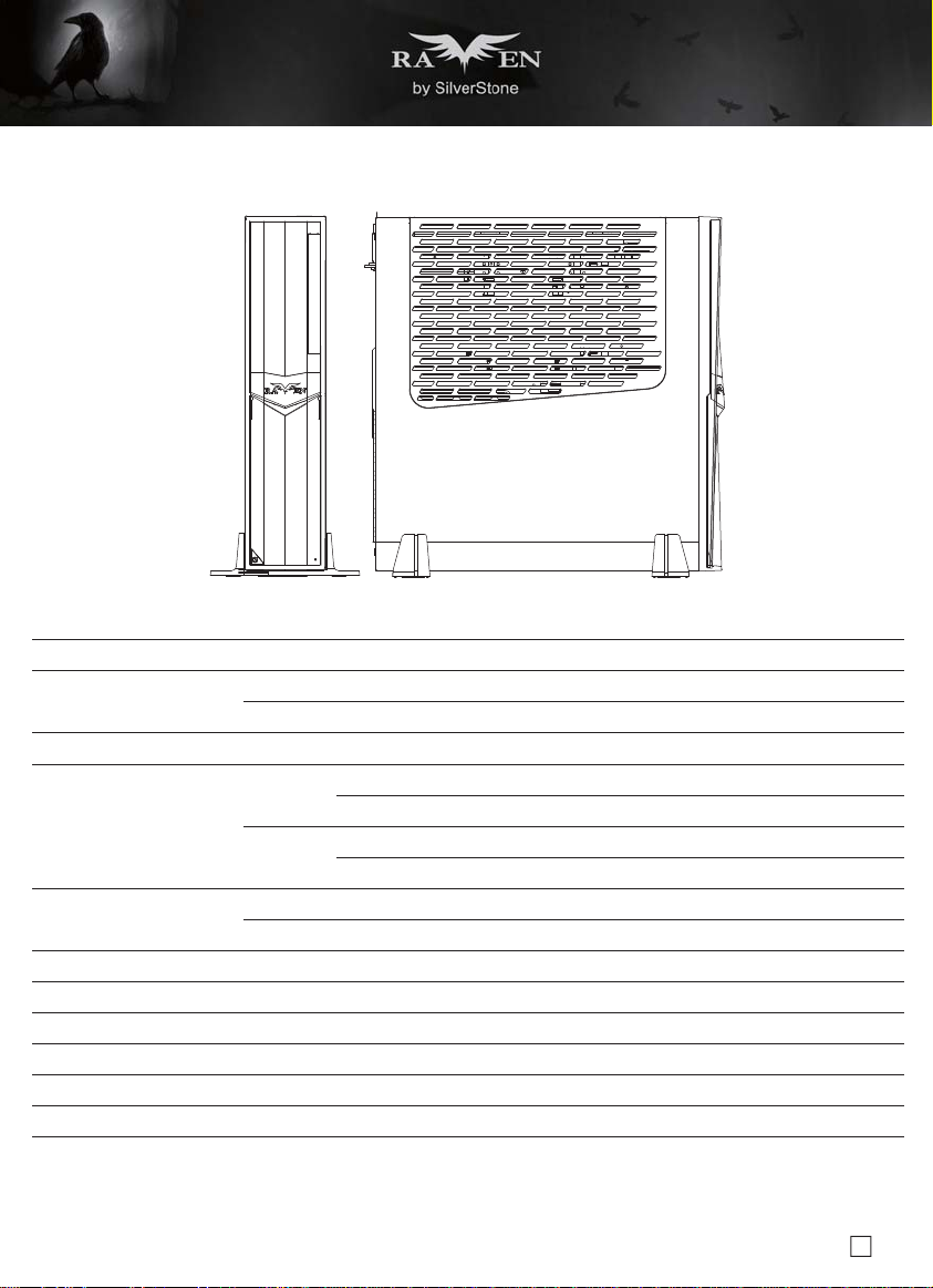
Dimension
Extra
*Expansion card holder needs to be removed when installing expansion/graphics card wider than 4.78 inches.
When system is assembled without the holder, vertical orientation of the case is recommended and transporting/shipping should be avoided.
For more details, please refer to manual.
Reinforced plastic outer shell, steel body
SST-RVZ02B (black)
SST-RVZ02B-W (black + window)
Mini-ITX
External
Internal
Sides
Rear
2
USB 3.0 x 2, Audio x 1, MIC x 1
SFX & SFX-L
*Compatible with 13” long, width restriction – 4.78”
58mm
380mm (W) x 87mm (H) x 370mm (D), 12 liters
Support two Kensington locks
Slim slot-loading optical 12.7mm or 9.5mm x 1
(9.5mm compatibility limited to tray type)
2.5” x 2
(one additional 3.5” or 2.5” space depending on expansion card installed)
Oversized vents over CPU/motherboard and expansion area
Passive exhaust vents
2
Page 4
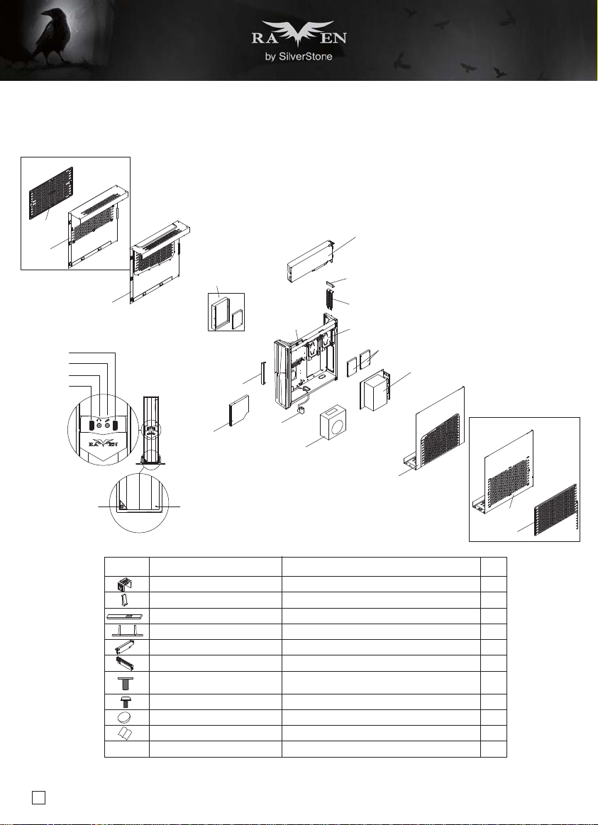
Disassemble Chart
W/O WINDOW TYPE
FILTER
COVER
COVER WINDOW
USB
MIC
SPK
USB
POWER RESET
3.5” HDD (OPTION) OR
2.5” HDD (OPTION)
SLIM ODD BKT
SLIM ODD COVER
SLIM ODD
(OPTION)
ITEMPICTURE PURPOSE QTY
CARD HOLDER BKT
PSU CLIP
SLIM CDR 95 TO 127 PANEL
FOOT
PCIE RISER CARD
PCIE EXPEND CARD
I-632-5-BK
PW-M3-4-BK
RUBBER FEET
MANUAL
CABLE TIE
PSU EXTEND
CABLE
ADD ON CARD (OPTION)
CARD BKT
2 x SLOT COVER
2.5” HDD BKT
2.5” HDD (OPTION)
MB (OPTION)
SFX PSU (OPTION)
COVER WINDOW
MB X 4, PSU X3, PCIE RISER CARD X2
PSU CLIP X2, 3.5” HDD X4, CARD HOLDER X1
2.5” HDD X 4
W/O WINDOW TYPE
COVER
FILTER
1
1
1
2
1
1
16
4
4
1
3
3
Page 5
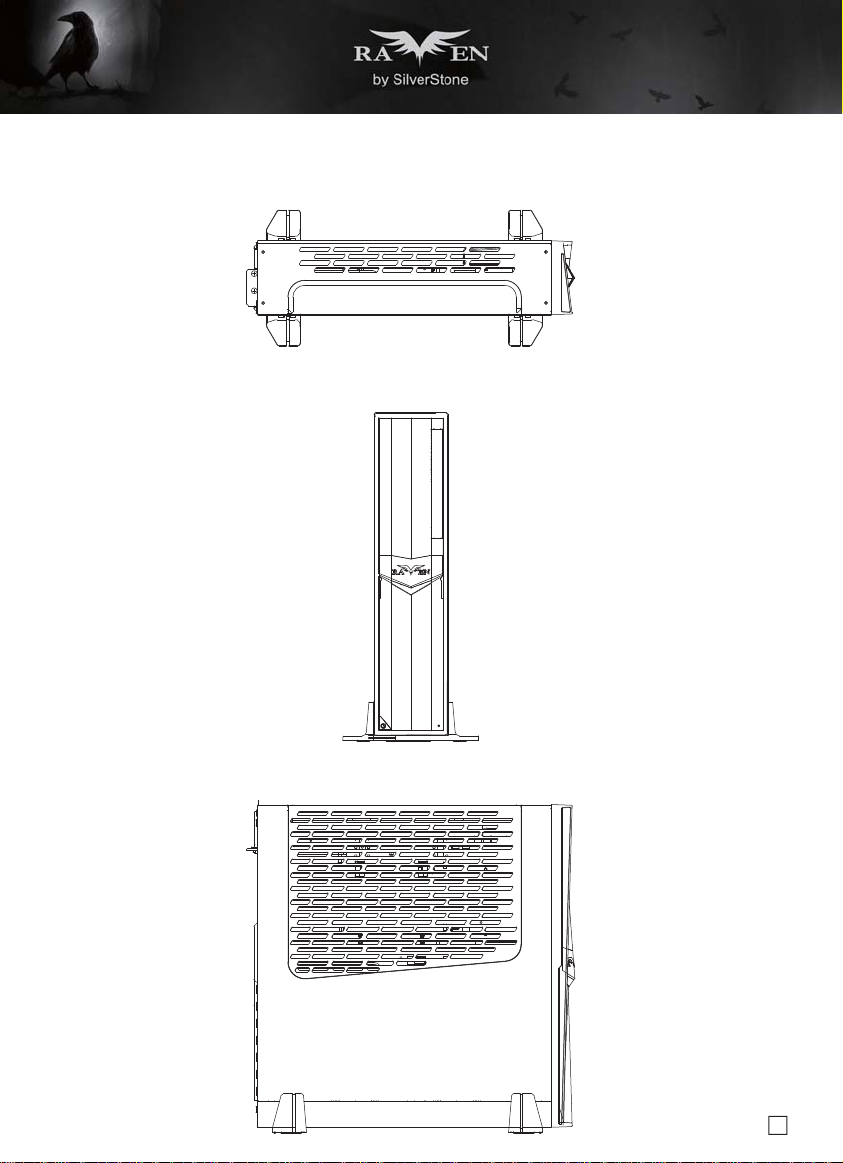
Disassemble Chart
TOP
FRONT
SIDE
4
Page 6
lnstallation Guide
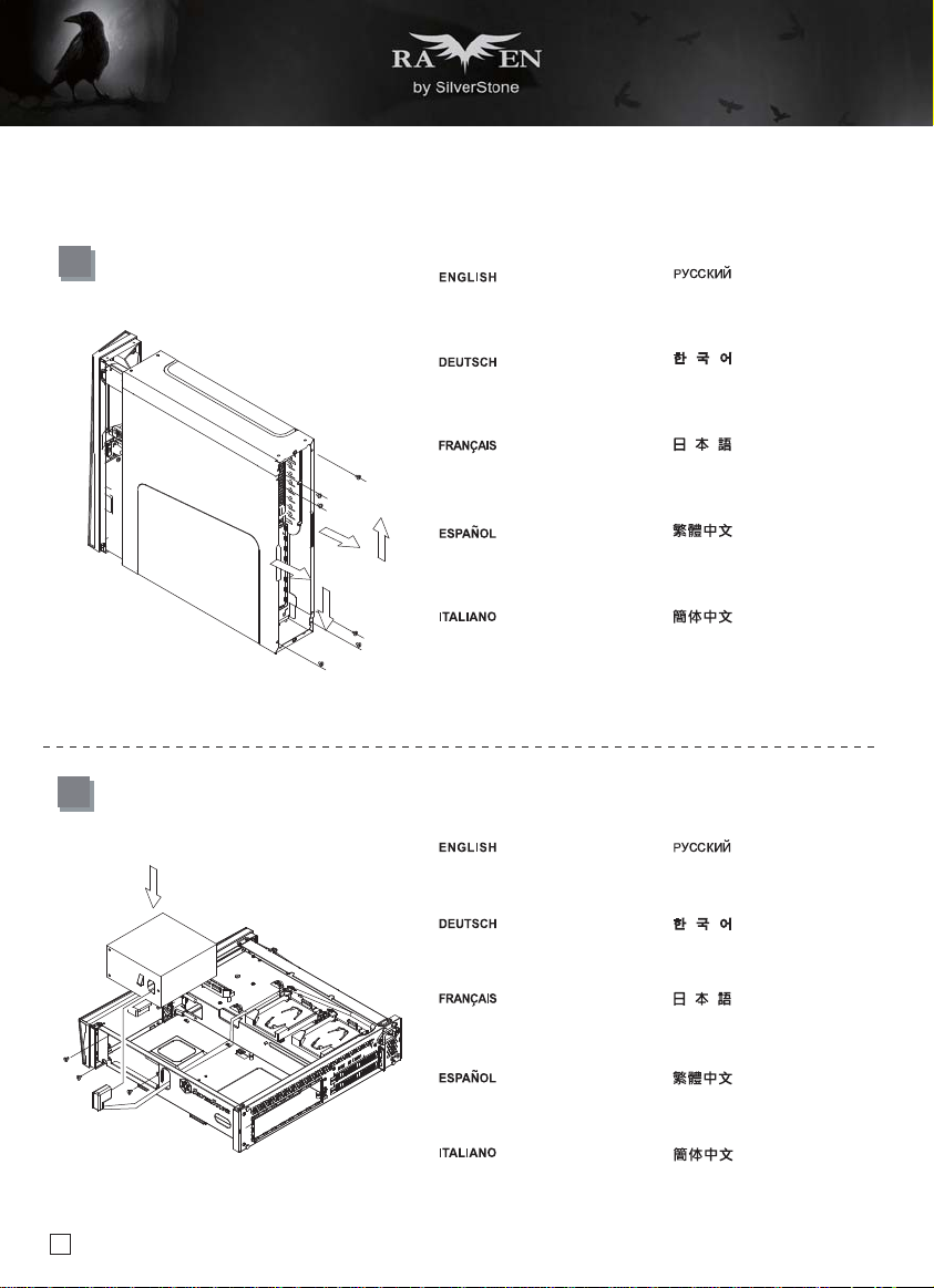
1
Loosen screws from both side panels
to remove them
Отверните винты крепления обеих
боковых панелей и снимите их
Schrauben an beiden Seitenblenden
lösen und diese entfernen
Dévissez les vis des deux panneaux
latéraux afin de les retirer
Afloje los tornillos de ambos paneles
laterales para retirarlos
Allentare le viti da entrambi i pannelli
laterali per rimuoverli
양쪽 패널의 나사를 풀어서 뺍니다
両側のパネルのネジを緩めて取り外
します
鬆開兩邊側板螺絲,取下側板
松开两边侧板螺丝,取下侧板
2
Install power supply and connect it
to the power cord extension cable
Netzteil installieren und mit dem
Verlängerungskabel des Stromkabels
verbinden
Installez le bloc d'alimentation et
raccordez-le au câble prolongateur
du cordon d'alimentation
Установите блок питания и
подключите к нему удлинительный
кабель питания
전원 공급장치를 설치한 다음 전원
코드 연장 케이블에 연결합니다
電源装置を取り付け、電源延長ケー
ブルを接続します
Instale la fuente de alimentación y
conéctelo al cable extensor del cable
de potencia
Installare l’alimentatore e collegarlo
alla prolunga del cavo di
alimentazione
5
安裝電源,並連接電源延長線
安装电源,并连接电源延长线
Page 7

lnstallation Guide
3
Unscrew the screws from PSU
bracket then remove it
Установите кронштейн блока
питания
Netzteilhalterung installieren
Installez le support du bloc
d'alimentation
Instale el bracket de la fuente de
alimentación
Installare la staffa PSU
4
If you want to mount a 2.5”HDD/SSD
on the center brace, we recommend
you to remove it in this step
Motherboard-I/O-Platte einsetzen,
dann das Motherboard im Gehäuse
installieren
Insérez la plaque d'E/S de la carte
mère puis installez la carte mère
dans le boîtier
전원 공급장치 브래킷을 설치합니다
PSUケージのネジを緩めて取
り外します
安裝電源固定支架
安装电源固定支架
Установите плату ввода-вывода
системной платы, затем
системную плату установите
в корпус
마더보드 I/O 플레이트를 끼운
다음 마더보드를 케이스에
끼웁니다
電源ブラケットを取り付けます
Inserte la bandeja de E/S de la placa
base y luego instale la placa base
en la carcasa
Inserire la piastra I/O della scheda
madre, quindi installare la scheda
madre nel case
將I/O彈片後檔板裝上機殼,
裝上主機板
将I/O弹片后档板装上机壳,
装上主板
6
Page 8
lnstallation Guide
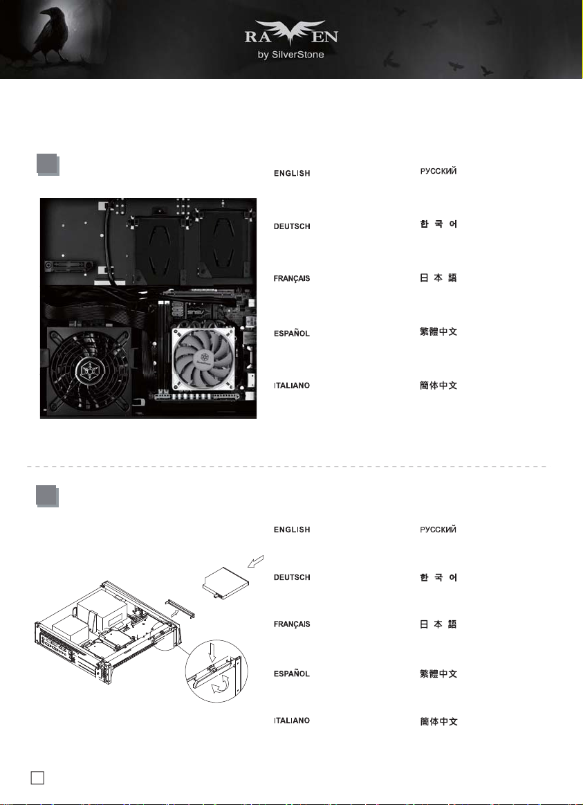
5
We recommend connecting all front
I/O and motherboard power cables
now
Wir empfehlen, nun sämtliche
frontseitigen I/O- und MotherboardStromkabel anzuschließen
В этот момент рекомендуется
подключить все кабели вводавывода и питания системной платы
на лицевой панели
이제 전면의 I/O 케이블과 마더보드
전원 케이블을 모두 연결할 것을
권장합니다
Nous conseillons à ce stade de
raccorder toutes les E/S de la face
avant ainsi que les câbles
d'alimentation de la carte mère
Le recomendamos conectar todos
los cables frontales de E/S y los
cables de potencia de la placa
base ahora
Si raccomanda di collegare a questo
punto tutti i cavi I/O ed i cavi di
alimentazione della scheda madre
この時点で全てのフロントI/Oおよび
マザーボード電源ケーブルを接続す
るようお勧めします
我們建議此時可以先連接機殼的前
I/O與主機板的電源線材
我们建议此时可以先连接机壳的前
I/O与主板的电源线材
6
Remove optical drive slot cover
and install optical drive
Abdeckung des ODD-Fachs
entfernen und das optische Laufwerk
installieren
Retirez le couvercle de l'emplacement
du lecteur optique et installez le
lecteur optique
Retire la cubierta del zócalo del
dispositivo óptico e instale el
dispositivo óptico
Снимите крышку слота оптического
привода и установите привод
оптических дисков
광 드라이브 슬롯 커버를 제거하고
광 드라이브를 설치합니다
光学ドライブスロットカバーを外し、
光学ドライブを取り付けます
移除光碟機檔片,安裝光碟機
Rimuovere il coperchio dell’alloggio
dell'unità ottica ed installare l’unità
ottica
7
移除光驱文件片,安装光驱
Page 9
lnstallation Guide
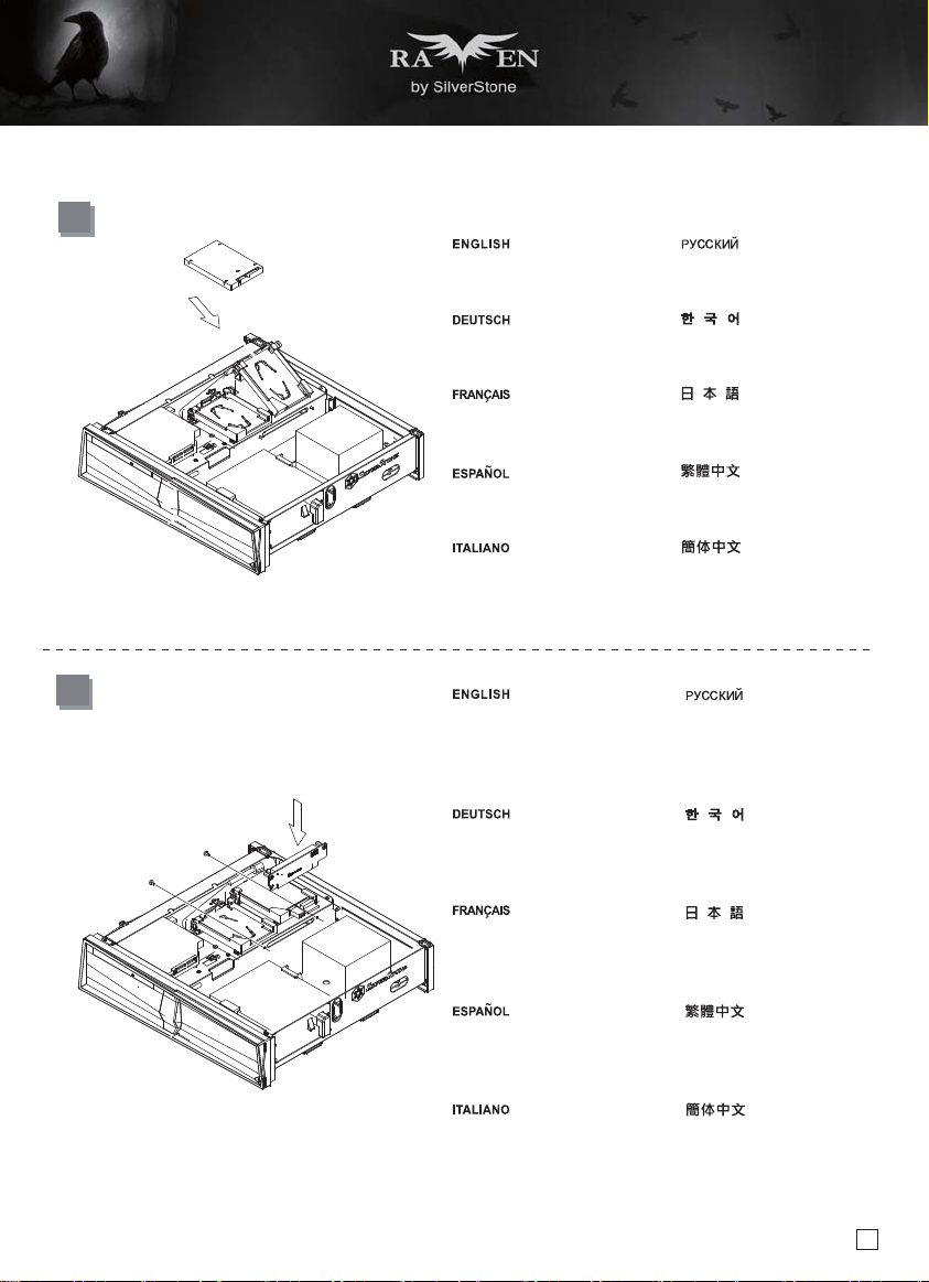
7
Squeeze the tool-less clips on both
sides of the drive cage to open it,
then insert 2.5” drive and close the
cage
Die werkzeuglosen Klemmen an
beiden Seiten des Laufwerkkäfigs
zum Öffnen zusammendrücken,
dann 2,5-Zoll-Laufwerk einsetzen
und den Käfig schließen
Appuyez sur les attaches sans outil
des deux côtés de la cage du lecteur
pour l'ouvrir, puis insérez le lecteur
2,5" et refermez la cage
Нажмите на фиксаторы по обеим
сторонам отсека для дисков, чтобы
открыть его, затем установите
2,5-дюймовый диск и закройте
отсек для дисков
드라이브 케이지 양쪽에 있는 공구가
필요 없는 클립을 꽉 눌러서 케이지를
연 다음 2.5" 드라이브를 끼우고
케이지를 닫습니다
ドライブケージ両側の工具不要クリ
ップを押さえて開き、2.5”ドライ
ブを装着してからケージを閉じます
Apriete los enganches sin
herramientas a ambos lados de la
carcasa de dispositivos para abrirla,
luego inserte el dispositivo de 2,5” y
cierre la carcasa
Premere le clip su entrambi i lati
della gabbia HDD per aprirla, quindi
inserire l’unità da 2,5" e chiudere la
gabbia
8
Install PCI Express riser card and
secure with screws
PCI-Express-Riserkarte installieren
und mit Schrauben sichern
Installez la carte adaptatrice PCI
Express et fixez-la avec des vis
Instale la tarjeta elevadora PCI
Express y fíjela con tornillos
Installare il riser scheda PCI Express
e fissare con le viti
按壓免螺絲硬碟架兩側並向外拉出,
安裝2.5吋硬碟後壓回固定
按压免螺丝硬盘架两侧并向外拉出,
安装2.5吋硬盘后压回固定
Установите райзер-карту PCI
Express и закрепите ее винтами
PCI Express 라이저 카드를 끼우고
나사로 고정합니다
PCI Expressライザーカードを取り
付け、ネジで固定します
安裝PCIE轉接卡,並從另一面鎖
上螺絲
安装PCIE转接卡,并从另一面锁
上螺丝
8
Page 10
lnstallation Guide
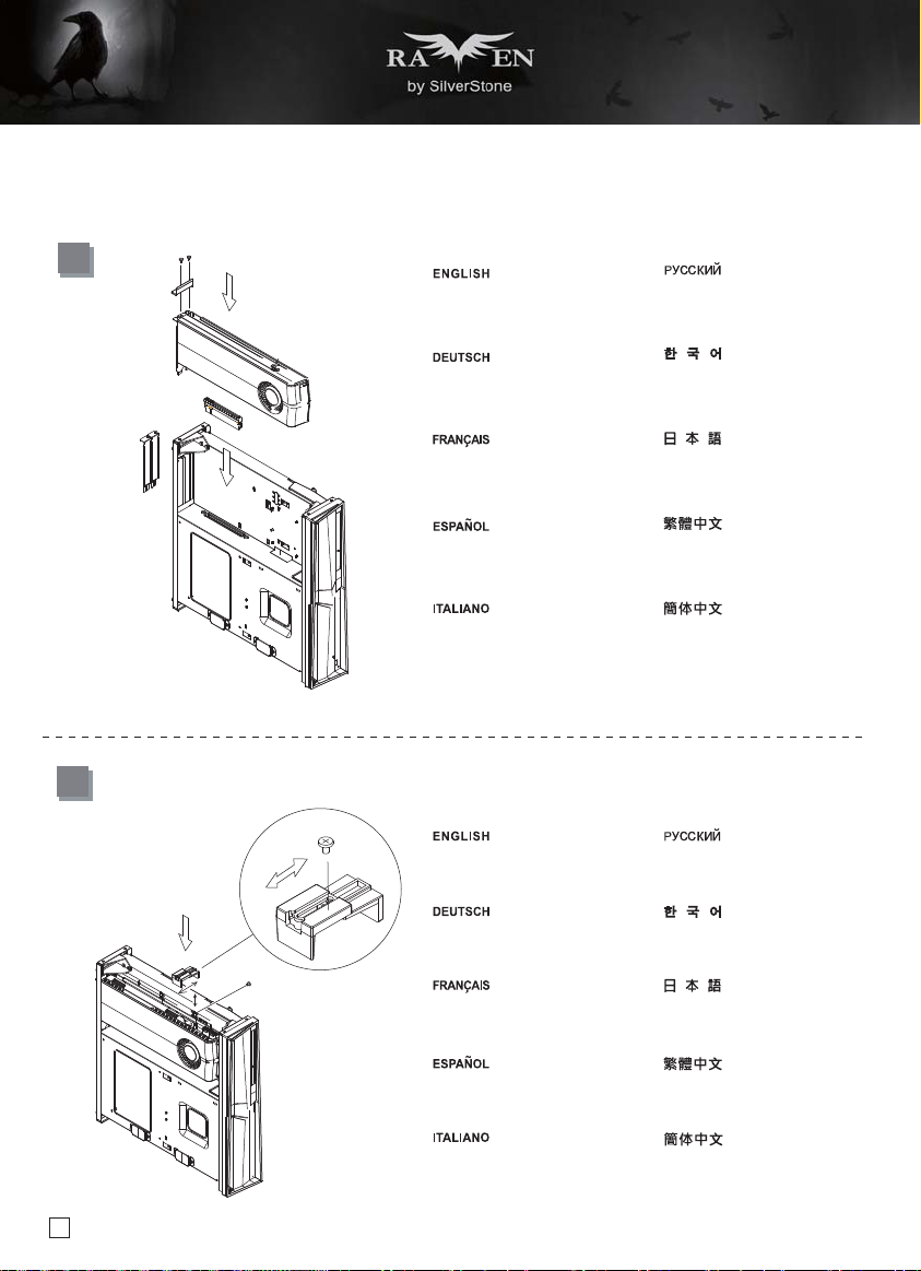
9
Loosen the screws holding the
expansion slot covers to remove
them, then install expansion card into
the PCI Express riser card
Befestigungsschrauben der
Erweiterungssteckplatzabdeckungen
zum Entfernen lösen, dann
Erweiterungskarte in der PCI-ExpressRiserkarte installieren
Desserrez les vis de maintien des
couvercles de l'emplacement
d'extension pour les enlever, puis
installez la carte d'extension dans la
carte adaptatrice PCI Express
Afloje los tornillos que sujetan las
cubiertas del zócalo de expansión
para retirarlas, luego instale la tarjeta
de expansión en la tarjeta elevadora
PCI Express
Отверните винты крышек слота
расширения и снимите их, затем
установите карту расширения в
райзер-карту PCI Express
확장 슬롯 커버를 고정하고 있는 나사를
풀어서 커버를 제거한 다음 확장 카드를
PCI Express 라이저 카드 안에
설치합니다
拡張スロットカバーを固定している
ネジを緩めて取り外し、拡張カード
をPCI Expressライザーカードに装
着します
鬆開螺絲,拆下顯示卡擋板,將顯示
卡安裝於PCIE 轉接卡插槽
10
9
Allentare le viti che fissano i coperchi
degli alloggi d’espansione per
rimuoverli, quindi installare la scheda
di espansione nel riser scheda PCI
Express
If needed, install expansion card
brace for extra security
Bei Bedarf Klammer für
Erweiterungskarte für zusätzliche
Sicherheit installieren
Si nécessaire, installez une attache
de carte d'extension pour plus de
sécurité
Si es necesario, instale el soporte
de la tarjeta de expansión para
seguridad extra
Se necessario, installare il sostegno
scheda di espansione per una
maggiore sicurezza
松开螺丝,拆下显示卡挡板,将显示
卡安装于PCIE 转接卡插槽
При необходимости установите скобу
карты расширения для ее
дополнительной фиксации
추가 보안을 위해 필요할 경우 확장
카드 죔쇠를 설치합니다
必要であれば、より確実な設置のた
めに拡張カードブレースを装着します
視需求,安裝顯示卡支撐架以強化固定
视需求,安装显示卡支撑架以强化固定
Page 11

lnstallation Guide
11
Connect all remaining cables
and wires
Подключите остальные кабели
и провода
12
Alle verbleibenden Kabel und
Drähte anschließen
Branchez tous les câbles et les
fils restants
Conecte todos los cables restantes
Collegare tutti i fili e cavi rimanenti
Reinstall both side panels Установите на место боковые
Beide Seitenblenden wieder
installieren
Réinstallez les deux panneaux
latéraux
나머지 케이블과 와이어를 모두
연결합니다
残りのケーブルおよびリード線を
全て接続します
連接所有線材
连接所有线材
панели
양쪽 패널을 도로 설치합니다
両側のパネルを元に戻します
Reinstale ambos paneles laterales
Reinstallare entrambi i pannelli
laterali
裝回兩邊側板
装回两边侧板
10
Page 12

lnstallation Guide
13
Depending on intended usage, use
corresponding case stands for
horizontal or vertical orientation
Je nach vorgesehenem Einsatz
entsprechende Gehäuseständer zur
horizontalen oder vertikalen
Aufstellung verwenden
Selon l'utilisation prévue, employez
les supports de boîtier correspondant
à une orientation horizontale ou
verticale
В зависимости от условий эксплуатации
используйте соответствующие стойки
для горизонтального или вертикального
размещения
용도에 따라 해당 케이스를 수평이나
수직 방향으로 세워서 사용합니다
使用目的に応じて横置きまたは縦置き
用のケーススタンドを使用します
Dependiendo del uso que se le
quiera dar, use los soportes
correspondientes de la carcasa
para orientación horizontal o vertical
In base all'utilizzo previsto, utilizzare
il corrispondente supporto case per
l’orientamento orizzontale o verticale
視需求,安裝橫躺或直立的腳墊
视需求,安装横躺或直立的脚垫
11
Page 13
Connector definition
(1) Front Panel Connectors
Guide:
Front panel connector installation no polarity, so they can be connected in any orientation
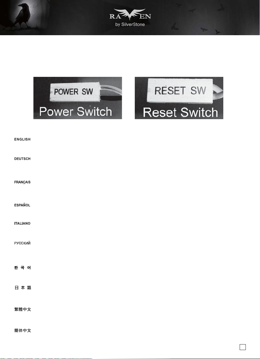
A.Power switch and reset switch installation guide:
Please refer to the motherboard manuals for the motherboard’s “Front Panel Connector” or “System Panel Connector” pin definitio
Power switch and reset switch have no polarity, so they can be connected in any orientation.
Bitte suchen Sie in der Motherboard-Dokumentation nach der Pinbelegung der Anschlüsse des Frontbedienfeldes („Front Panel Conne
oder „ System Panel Connectors“). Ein-/Austaste und Rücksetztaste benötigen keine bestimmte Polarität, können daher beliebig (o
und - zu achten) angeschlossen werden.
Veuillez-vous référer au manuel de votre carte mère pour la description des broches "des connecteurs du panneau frontal" et des
"des connecteurs du panneau système". Les interrupteurs d'allumage et de réinitialisation ne possède pas de polarité, donc ils peuvent être
branché dans les deux sens.
Por favor, consulte en los manuales de la placa base la configuración de pines del “Conector de panel frontal” ó “Conector de panel de sistema”
de su placa base. Los interruptores de encendido y reseteo no tienen polaridad, luego se pueden conectar con cualquier orientac.
Fare riferimento al manuale della scheda madre nella sezione “Connettori del pannello frontale” o “Connettori del pannello di sistema”. Power
switch e reset switch non hanno polarità, posso essere pertanto connessi con qualsiasi orientamento.
Описание контактов разъемов приведены в разделах “Разъемы передней панели” или “Разъемы системной панели” руководства
пользователя материнской платы. Выключатель питания и кнопка перезагрузки не имеют полярности, поэтому их можно подключать
в любой ориентации.
메인보드 매뉴얼의 전면패널 커넥터 혹은 시스템패널 커넥터 핀을 참조하기 바랍니다. 파워 스위치와 리셋 스위치는 극 성이 없어 어떤
방향으로 설치해도 무방합니다.
マザーボードの「フロントパネルコネクタ」または「システムパネルコネクタ」のピン配列についてはマザーボードマニュアルを参照してください。
電源スイッチとリセットスイッチに極性はないので、いずれの方向でも接続できま。
請參考主機說明書的Front Panel Connectors安裝Pin Define,將Connector插上;Power Switch 與Reset Switch並無正負極性之分,
反插正插都不影響功能性。
请参考主机说明书的Front Panel Connectors安装Pin Define,将Connector插上;Power Switch 与Reset Switch并无正负极性之分,
反插正插都不影响功能性。
12
Page 14

Connector definition
(1) Front Panel Connectors
B:LED indicators installation guide
Please refer to the motherboard manuals for the motherboard’s “Front Panel Connector ” or “System Panel Connector” pin definition.; the white/black
wires are negative while other colors are positive wires. The Power LED wires are separate pins for compatibility with different motherboard pin
definition so please make sure they are connected in the right polarity by referring to your motherboard manual.
Bitte suchen Sie in der Motherboard-Dokumentation nach der Pinbelegung der Anschlüsse des Frontbedienfeldes („Front Panel Connectors“ oder „
System Panel Connectors“). Die weißen/ schwarz Adern sind negativ (-), die farbigen Adern positiv (+).Die Kabel für die Betriebsanzeige-LED sind
zur Kompatibilität mit unterschiedlichsten Motherboards einzeln, nicht als kompletter Stecker ausgeführt. Achten Sie hier bitte auf die richtige
Polarität, lesen Sie in der Dokumentation Ihres Motherboards nach.
Veuillez-vous référer au manuel de votre carte mère pour la description des broches "des connecteurs du panneau frontal" et des broches "des connecteurs du panneau
système". Les câbles colorés en blanc/noir sont négatifs alors que ceux d'une autre couleur sont positifs. Les câbles de la LED Power sont séparés afin d'être compatible
avec différentes cartes mères, donc vérifiez bien qu'ils sont branchés avec la bonne polarité en vous référant au manuel de votre carte mère.
Por favor, consulte en los manuales de la placa base la configuración de pines del “Conector de panel frontal” ó “Conector de panel de sistema” de
su placa base. Los cables de color blanco/negro son negativos mientras que los de color son positivos. Los cables LED de potencia tienen pines
separados para compatibilidad con diferentes definiciones de pines de la placa base luego por favor, asegúrese de que están conectados en la
polaridad correcta consultando el manual de su placa base.
Fare riferimento al manuale della scheda madre nella sezione “Connettori del pannello frontale” o “Connettori del pannello di sistema”. I cavi di
colore bianco/nero sono il polo negativo, mentre quelli di colore diverso il positivo.
Описание контактов разъемов приведены в разделах “Разъемы передней панели” или “Разъемы системной панели” руководства
пользователя материнской платы. Белые/черный провода - отрицательной полярности, цветные провода - положительной полярности.
Провода светодиодного индикатора питания имеют отдельные контакты для совместимости с различными типами контактов материнских
плат, поэтому обратитесь к руководству пользователя материнской платы и убедитесь, что полярность соблюдена.
메인보드 매뉴얼의 전면패널 커넥터 혹은 시스템패널 커넥터 핀을 참조하기 바랍니다. 하얀/검은선의 경우 음극이며, 다른 색의 경우
양극입니다. 파워 LED 선은 분리되어 다양한 메인보드에서 동작할 수 있도록 되어 있습니다. 그러므로 메인보드 매뉴얼을 참조하여 올바를
극성을 주의해 선택하시기 바랍니다.
マザーボードの「フロントパネルコネクタ」または「システムパネルコネクタ」ピン配列についてはマザーボードマニュアルを参照してください。
白/黑色のリード線はマイナスで、色の着いたリード線がプラスです。電源LEDリード線は種々のマザーボードピン定義と互換性を持たせるため分離されたピ
ンとなっているので、ご使用のマザーボードマニュアルを参照して、適切な極性に接続されるようお確かめください。
請參考主機說明書的Front Panel Connectors安裝Pin Define,將Connector插上;白/黑色線的部分為負極,彩色線的部分是正極。
Power LED為了適應各主機板的不同, 特別設計為散Pin樣式,請安心使用。
请参考说明书的Front Panel Connectors安装Pin Define,将Connector插上;白/黑色线的部份为负极,彩色线的部份为正极。
Power LED为了适应主机板的不同, 特别设计为散Pin样式,请安心使用。
13
Page 15

Connector definition
(2) Front I/O connector guide
Below are the front I/O connectors pin definition, please also check your motherboard manual to cross reference with motherboard’s
front I/O pin headers. SilverStone’s I/O connectors are in block type to simplify installation.
Nachstehend finden Sie die Pinbelegung der vorderen E/A-Anschlüsse; bitte gleichen Sie zudem das Handbuch Ihres Motherboards mit
den vorderen E/A-Pinzuweisungen ab. SilverStones E/A-Anschlüsse befinden sich zur Vereinfachung der Installation in Blockart.
Au dessous de la description des broches des ports d'E/S, veuillez aussi vérifier sur le manuel de votre carte mère de manière croisée
que les broches sont correctement placées. Les connecteurs d'E/S de SilverStone sont en bloc pour en simplifier leur installation.
A continuación tiene la definición de pines de los conectores frontales de E/S, también debe consultar el manual de su placa base para c
omprobar la referencia de los pines para E/S frontales. Los conectores de E/S de SilverStone son de bloque para simplificar la instalación.
Di seguito lo schema delle connessioni I/O frontali, confrontare lo schema con quanto riportato sul manuale della scheda madre per
effettuare una controllo incrociato. I connettori I/O Silverstone, per semplificare l’installazione, sono del tipo “a blocco”.
Ниже приведено описание контактов передних разъемов ввода/вывода. Обратитесь также к руководству пользователя материнской
платы за описанием передних разъемов ввода/вывода типа "пин-хедер". Разъемы ввода/вывода "SilverStone" - блочного типа, что
облегчает сборку.
아래는 전면 I/O 커넥터의 핀 설정이며, 메인보드 매뉴얼을 참조해 메인보드의 전면 I/O 핀 헤더와 맞추어 설치합니다.
Silverstone의 I/O 커낵터는 블록 타이브로 구성되어 설치를 간편화 했습니다.
以下はフロントI/Oコネクタピン配列ですが、お持ちのマザーボードのフロントI/Oピンヘッダは、マザーボードマニュアルをご参照ください。
シルバーストーンのI/Oコネクタは、インストールの容易なブロックタイプになっています。
下表為Front I/O Connectors的Pin Define,請參閱主機板說明書的各Front I/O Connectors Pin Define一一核對。
Front I/O Connectors完全採用集合Pin方式以簡化安裝。
下表为Front I/O Connectors的Pin Define,请参阅主机板说明书的各Front I/O Connectors Pin Define一一核对。
Front I/O Connectors完全采用集合Pin方式以简化安装。
14
Page 16

Component size limitations
The RVZ02 was designed to be as small as possible while maximizing interior space usage, please refer to the following guidelines for component
selection and future upgrade considerations.
(1) CPU cooler height limitation
58
Height limitation: The RVZ02 has 58mm height limitation for CPU cooler.
4
Upper boundary: The cooler can protrude 15mm over the motherboard’s top edge.
Front boundary: The clearance toward the front of the chassis is 4mm.
Höhenbeschränkung: Das RVZ02 unterstützt beim CPU-Kühler eine Maximalhöhe von 58 mm.
Obere Grenze: Der Kühler kann 15 mm über die Motherboard-Oberkante hinausstehen.
Vordere Grenze: Der Abstand Richtung Vorderseite des Gehäuses beträgt 4 mm.
Limitation de la hauteur : Le RVZ02 a une limitation de hauteur de 58mm pour le refroidisseur de CPU.
Limite supérieure : Le refroidisseur peut dépasser de 15mm sur le bord supérieur de la carte mère.
Limite avant : Le dégagement vers l'avant du châssis est 4 mm.
Limitación de altura: el RVZ02 tiene una limitación de altura de 58mm para un disipador de CPU.
Límite superior: el disipador puede sobresalir 15mm sobre el límite superior de la placa base.
Límite frontal: el espacio libre hacia la parte frontal del chasis debe ser de 4mm.
Limitazioni dell’altezza: RVZ02 ha una limitazione di 58 mm in altezza per il dispersore di calore CPU.
Limite superiore: il dispersore di calore può sporgere di 15 mm dal bordo superiore della scheda madre.
Limite anteriore: Lo spazio libero verso la parte anteriore del telaio è di 4 mm.
Ограничение по высоте: Корпус RVZ02 для установки вентилятора охлаждения процессора имеет ограничение по высоте 58мм.
Верхний край: вентилятор может выступать на 15 мм над верхним краем системной платы.
Передний край: Зазор до передней стороны корпуса должен составлять 4 мм.
높이 제한: CPU 쿨러에 대한 RVZ02의 높이 제한은 58mm입니다.
상한: 쿨러는 메인보드 상단 가장자리 위로 15mm까지 돌출할 수 있습니다.
전방 한계: 섀시 전면 쪽 간극은 4mm입니다.
高さ制限:RVZ02には、CPUクーラーに対して58mmの高さ制限があります。
上限:クーラーは、マザーボードの上端の上方15mmまで突出できます。
正面の制限:ケースの正面の方の許容範囲は4mmです。
高度限制: CPU Cooler限高是58mm
上邊界: CPU Cooler允許超出主機板上邊緣15mm
前邊界: CPU Cooler允許超出主機板前邊界4mm
15
高度限制: CPU Cooler限高是58mm
上边界: CPU Cooler允许超出主板上边缘15mm
前边界: CPU Cooler允许超出主板前边界4mm
15
Page 17
Component size limitations
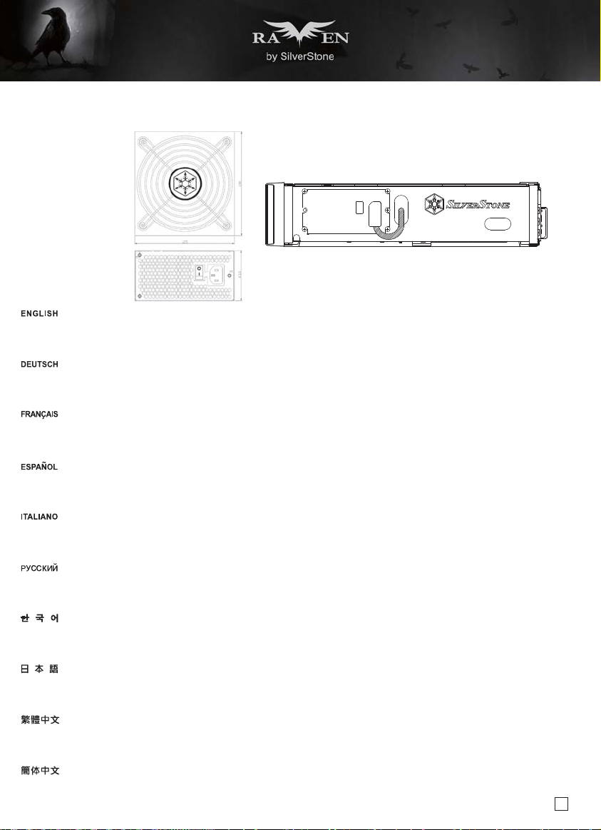
(2) PSU limitation
RVZ02 requires standard SFX or SFX-L power supplies with maximum depth of 130mm
In the illustration, the PSU is situated in the front part of the chassis with the 90 degrees connector extension cable installed. The extension cable shall
not exceed the upper or the lower boundary.
RVZ02 erfordert standardmäßige SFX- oder SFX-L-Netzteile mit einer maximalen Tiefe von 130 mm
In der Abbildung befindet sich das Netzteil im vorderen Bereich des Gehäuses; mit installiertem Verlängerungskabel mit 90-Grad-Anschluss. Das
Verlängerungskabel darf die obere und untere Grenze nicht überschreiten.
Le RVZ02 nécessite une alimentation standard SFX ou SFX-L avec une profondeur maximale de 130 mm.
Dans l'illustration, l'unité d'alimentation est située dans la partie avant du châssis avec le câble d'extension et un connecteur de 90 degrés. Le câble
d'extension ne doit pas dépasser la limite supérieure ou inférieure.
La RVZ02 necesita fuentes de alimentación estándar SFX o SFX-L con una profundidad máxima de 130mm
In the illustration, the PSU is situated in the front part of the chassis with the 90 degrees connector extension cable installed. The extension cable shall
not exceed the upper or the lower boundary.
RVZ02 richiede alimentatori standard SFX o SFX-L, con una profondità massima di 130 mm
Nell'illustrazione, la PSU si trova sulla parte anteriore del telaio ed è dotata di prolunga con connettore a 90 gradi. La prolunga non deve superare il
limite superiore o inferiore.
Для корпуса RVZ02 требуется стандартный блок питания SFX или SFX-L с максимальной глубиной 130 мм
На рисунке блок питания размещен в передней части корпуса с помощью кабеля с уголковым (90 градусов) разъемом. Кабель не должен
выходить за пределы верхнего или нижнего края.
RVZ02에는 깊이가 최대 130mm인 표준 SFX 또는 SFX-L 모델 전원 공급장치를 사용해야 합니다.
그림에서 PSU는 90도 커넥터 확장 케이블이 설치된 상태에서 섀시의 앞 부분에 위치합니다. 확장 케이블은 상한 또는 하한을 초과해서는 안 됩니다.
RVZ02には、最大奥行130mmの標準SFXまたはSFX-L電源が必要です。
図中では、PSUは90度コネクタ拡張ケーブルを使用して、ケース前方に設置されています。拡張ケーブルは、上限や下限を超えないようにします。
RVZ02限定使用標準SFX或SFX-L電源,深度限制為130mm
如圖,RVZ02電源前置,在內部使用90度的延長線,延長線安裝上後不允許往上或往下超出邊界
RVZ02限定使用标准SFX或SFX-L电源,深度限制为130mm
如图,RVZ02电源前置,在内部使用90度的延长线,延长线安装上后不允许往上或往下超出边界
16
Page 18
Component size limitations
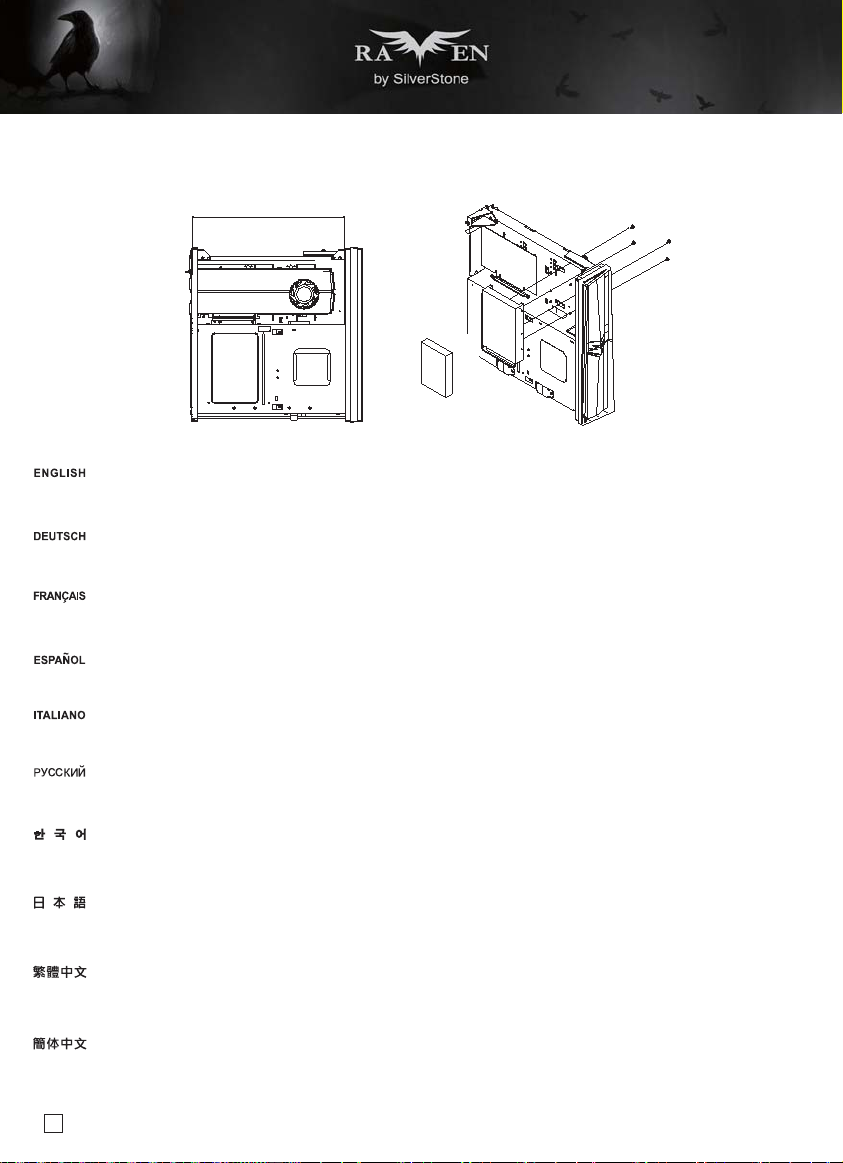
(3) Graphics card/expansion card length limitation
13"
2.5” HDD 3.5” HDD
OR
A. Length limitation
The RVZ02 can support 13”(330mm) consumer level graphics cards. Please contact us if you find a card that does not fit.
If the card used is shorter than 7.8” (200mm), then an additional 3.5” or 2.5” drive can be installed next to it. Please refer to diagram for this installation,
you will need to do this before installing optical drive.
Das RVZ02 nimmt bis zu 330 mm lange Grafikkarten auf. Bitte wenden Sie sich an uns, falls Sie keine passende Karte finden können.
Falls die verwendete Karte kürzer als 200 mm ist, kann daneben ein zusätzliches 3,5- oder 2,5-Zoll-Laufwerk installiert werden. Bitte beachten Sie
die Abbildung für diese Installation; Sie müssen diesen Schritt vor Installation des optischen Laufwerks durchführen.
Le RVZ02 peut supporter la plupart des cartes graphiques du marché de 13" (330mm). Veuillez nous contacter si vous trouvez une carte qui ne
correspond pas.
Si la longueur de la carte utilisée est inférieure à 7,8" (200 mm), il est possible d'installer un lecteur supplémentaire de 3,5" ou 2.5" à côté. Veuillez
consulter le schéma pour cette installation, vous devrez le faire avant d'installer le lecteur optique.
The RVZ02 can support 13”(330mm) consumer level graphics cards. Please contact us if you find a card that does not fit.
Si la tarjeta usada mide menos de 7,8” (200mm), entonces se podrá instalar un dispositivo adicional de 3,5” o 2,5” al lado. Por favor, consulte el
diagrama para esta instalación, necesitará hacer esto antes de instalar el dispositivo óptico.
RVZ02 può supportare schede grafiche da 13” (330 mm) di livello consumer. Vi preghiamo di contattarci se si trova una scheda che non si adatta
Se la scheda utilizzata è di lunghezza inferiore ai 7,8" (200 mm), accanto ad essa può essere installata una ulteriore unità da 3,5” o 2,5”. Fare
riferimento al diagramma per questa installazione, sarà necessario eseguirla prima di installare l'unità ottica.
Корпус RVZ02 допускает установку 13-дюймовых (330 мм) графических карт. Если ваша карта не устанавливается, свяжитесь с нами.
Если размер используемой карты менее 7,8 дюйма (200 мм), рядом с ней можно установить дополнительный 3,5-дюймовый или 2,5дюймовый привод. При необходимости см. таблицу по установке, прежде
чем устанавливать оптический привод.
RVZ01은 13”(330mm)의 소비자급 그래픽 카드를 지원합니다. 카드가 맞지 않으면 당사로 문의하십시오.
사용되는 카드가 7.8” (200mm)보다 짧을 경우 3.5” 또는 2.5” 드라이브를 그 옆에 추가로 설치할 수 있습니다. 이같은 설치 방법은 그림을
참조하십시오. 광 드라이브를 설치하기 전에 그림을 참조해야 합니다.
RVZ02は13インチ(330mm)消費者用グラフィックスカードに対応します。適合しないカードを発見した場合、当社にご連絡ください。
使用されるカードが7.8” (200mm)より短い場合、隣接して3.5”または2.5”ドライブが追加設置可能です。この設置は光学ドライブ設置より前に
行い、その際には図をご参照ください。
RVZ02支援到13”顯示卡,如果你找到裝不下的顯示卡請聯絡我們
如果顯示卡長度短於7.8”(200mm),則可於顯示卡側再額外安裝一顆3.5”或2.5”硬碟
安裝方式如圖,需在安裝光碟機之前先行安裝
RVZ02支持到13”显示卡,如果你找到装不下的显示适配器请联络我们
如果显示卡长度短于7.8”(200mm),则可于显示卡侧再额外安装一颗3.5”或2.5”硬盘
安装方式如图,需在安装光驱之前先行安装
17
Page 19

Component size limitations
(3) Graphics card/expansion card length limitation
B. Width limitation
4.78"
4.38"
The standard width for graphics card is 4.38”
With the graphics card holder installed, the maximum allowable width for graphics card is 4.78”
Without the graphics card holder, the maximum allowable width for graphics card is up to 6.15”
If there is interference with rear support structure, you may remove it
Die Standardbreite bei Grafikkarten beträgt 4,38”
Bei installierter Grafikkartenhalterung beträgt die maximal erlaubte Grafikkartenbreite 4,78”
Ohne installierte Grafikkartenhalterung beträgt die maximal erlaubte Grafikkartenbreite 6,15”
Falls es Probleme mit der hinteren Stützstruktur gibt, können Sie sie entfernen
La largeur standard pour les cartes graphiques est 4,38".
Avec le support de carte graphique, la largeur maximale permise pour les cartes graphiques est 4,78".
Sans le support de carte graphique, la largeur maximale permise pour les cartes graphiques est 6,15".
En cas d'interférence avec la structure du support arrière, vous pouvez le retirer
La anchura estándar para las tarjetas gráficas es de 4,38”.
Con el soporte para tarjetas gráficas instalado, la anchura máxima permitida para las tarjetas gráficas es de 4,78”
Sin el soporte para tarjetas gráficas, la anchura máxima permitida para tarjetas gráficas es de hasta 6,15
En caso de interferencia con la estructura de soporte trasera, podría retirarla.
La larghezza standard delle schede video è di 4,38”.
Quando è installato il supporto della scheda video, la larghezza massima consentita per la scheda video è di 4,78”
Quando non è installato il supporto della scheda video, la larghezza massima consentita per la scheda video è di 6,15”
In caso di interferenze con la struttura di sostegno posteriore, è possibile rimuoverlo
Стандартная ширина графической карты составляет 4,38 дюйма (11,1 см).
При установленном кронштейне графической карты максимально допустимая ширина графической карты составляет 4,78 дюйма (12,1 см).
Без установленного кронштейна графической карты максимально допустимая ширина графической карты составляет 6,15 дюйма (15,6 см).
Если задняя опора мешает, ее можно снять.
그래픽 카드의 표준 폭은 4.38”입니다.
그래픽 카드 홀더가 설치된 상태에서 그래픽 카드의 최대 허용 폭은 4.78”입니다.
그래픽 카드 홀더가 없는 상태에서 그래픽 카드의 최대 허용 폭은 6.15”입니다.
뒷면의 지지 구조물이 방해가 될 경우 제거해도 됩니다.
グラフィックスカードの標準的な幅は、4.38インチです。
グラフィックスカード・ホルダーを設置した場合、グラフィックスカードの最大許容幅は、4.78インチです。
グラフィックスカード・ホルダーなしでは、グラフィックスカードの最大許容幅は、6.15インチです。
後方のサポート構造とぶつかる場合、そのサポートを取り外すことも可能です。
標準顯示卡寬度是4.38”
如果有要使用輔助托架,支援最大寬度到4.78”(超過標準10mm)
如果不使用輔助托架,顯示卡寬度最多為6.15” (超過標準45mm)
如果干涉到後方補強件的話,可以拆除
标准显示卡宽度是4.38”
如果有要使用辅助托架,支持最大宽度到4.78”(超过标准10mm)
如果不使用辅助托架,显示卡宽度最多为6.15” (超过标准45mm)
如果干涉到后方补强件的话,可以拆除
6.15"
18
Page 20

Component size limitations
(3) Graphics card/expansion card length limitation
C. Thickness limitation
4.9
35
If expansion card brace is used, the limit is 35mm for top side of the card. If not used, the limit is 43mm
There is 4.9mm limit for backside of the card where expansion card brace is present, otherwise the limit is 7.9mm
If RVZ02 is to be used in horizontal orientation or transported often, we recommend installing expansion card brace. If the case is used in vertical
orientation and does not need to be moved often, you may opt not to install the brace for quicker upgrade or replacement of graphics/expansion card
in the future.
Falls die Erweiterungskartenklammer genutzt wird, beträgt das Limit für die Oberseite der Karte 35 mm. Andernfalls beträgt das Limit 43 mm.
Es gibt ein Limit von 4,9 mm für die Rückseite der Karte, wenn eine Erweiterungskartenklammer vorhanden ist; andernfalls beträgt das Limit 7,9 mm
Falls das RVZ02 in horizontaler Ausrichtung verwendet oder häufig transportiert werden soll, sollten Sie die Erweiterungskartenklammer installieren.
Wenn das Gehäuse in vertikaler Ausrichtung verwendet werden soll und nicht häufig transportiert werden muss, können Sie die Klammer zur schnellen
Aufrüstung oder Auswechslung der Grafik-/Erweiterungskarte weglassen.
Si le support de carte d’extension est utilisé, la limite est de 35mm pour le côté supérieur de la carte. Sinon, la limite est de 43mm
La limite pour l'arrière de la carte est de 4,9 mm si une attache de carte d'extension est présente. Sinon, la limite est de 7,9 mm
Si le RVZ02 doit être utilisé en position horizontale ou souvent transporté, nous conseillons d'installer l'attache de carte d'extension. Si le boîtier est
utilisé en position verticale et ne doit pas être souvent déplacé, vous pouvez choisir de ne pas installer l'attache pour une mise à niveau ou un
remplacement ultérieurs plus rapides de la carte graphique/d'extension.
Si se usa la abrazadera para la tarjeta de expansión, el límite es de 35mm para la parte superior de la tarjeta. Si no se usa, el límite es de 43mm.
Existe un límite de 4,9mm para la parte trasera de la tarjeta cuando esté presente el soporte de la tarjeta de expansión, en caso contrario el límite es
de 7,9mm.
Si la RVZ02 se usa en orientación horizontal o se transporta a menudo, le recomendamos instalar el soporte de la tarjeta de expansión. Si la carcasa
se usa en orientación vertical y no necesita moverse a menudo, podría optar por no instalar el soporte para cambios o reemplazos más rápidos de
tarjetas de expansión/gráficas en el futuro.
Se si utilizza il supporto della scheda di espansione, il limite è 35 mm per il lato superiore della scheda. Se non si utilizza, il limite è 43 mm.
Quando è presente il sostegno della scheda di espansione, il limite per la parte posteriore della scheda è di 4,9 mm, altrimenti è di 7,9 mm
Se RVZ02 deve essere utilizzato in posizione orizzontale o deve essere trasportato spesso, si raccomanda di installare il sostegno della scheda di
espansione. Se il case è utilizzato in posizione verticale e non c’è la necessità di spostarlo spesso, è possibile scegliere di non installare il sostegno
per poter aggiornare o sostituire più rapidamente la scheda grafica/di espansione in futuro.
43
7.9
Если используется скоба расширительной платы, ограничение для верхней стороны платы составляет 35 мм. Если она не используется,
ограничение составляет 43 мм.
Для задней стороны карты имеется зазор 4,9-мм, в котором установлен
составляет 7,9 мм
Если корпус RVZ02 используется в горизонтальном положении или часто транспортируется, рекомендуется установить кронштейн для карты
расширения. Если корпус используется в вертикальном положении и не требует частого перемещения, кронштейн можно не устанавливать
для быстрой модернизации или замены графической карты или карты расширения в дальнейшем.
확장 카드 브레이스를 사용할 경우, 카드 상단의 한계는 35mm이고, 사용하지 않을 경우는 43mm입니다.
확장 카드 죔쇠가 있는 경우 카드 뒷면에 최대 4.9mm의 여유 공간이, 죔쇠가 없는 경우 최대 7.9mm의 여유 공간이 있습니다.
RVZ02를 수평 방향으로 사용하거나 자주 이동시켜야 할 경우 확장 카드 죔쇠를 설치할 것을 권장합니다. 케이스를 수직 방향으로 사용하거나 자주
이동시킬 필요가 없을 경우, 나중에 그래픽 카드나 확장 카드를 신속하게 업그레이드하거나 교체하려면 죔쇠를 설치하지 않는 것이 좋습니다.
19
кронштейн карты расширения, в противном случае величина зазора
Page 21
Component size limitations
(3) Graphics card/expansion card length limitation
拡張カードブレース使用時は、カード上面の限度は35mmで、非使用時は限度43mmです。
カードブレースが設置されている場合、カード後方には4.9mmの限界があります。設置なしの場合は7.9mmとなります。
RVZ02が横置き、または頻繁に移動される場合は拡張カードブレースの設置をお勧めします。ケースが縦置き、または移動があまりない場合は、将
来に素早いアップグレードやグラフィックス/拡張カードの交換に対応できるよう、ブレースを装着しない選択も可能です。
如果使用輔助托架,正面元件限制35mm,不使用的話則為43mm
有被顯示卡托架接觸到的部分,顯示卡背面元件厚度限制4.9mm,未接觸到的部分厚度限制為7.9mm
若RVZ02是橫躺使用或需搬動運輸的情況下,建議安裝顯示卡輔助托架,若機器僅直立使用,且不經常運輸,可以暫時不安裝,方便日後快速替換升級
顯示卡。
如果使用辅助托架,正面组件限制35mm,不使用的话则为43mm
有被显示卡托架接触到的部分,显示卡背面组件厚度限制4.9mm,未接触到的部分厚度限制为7.9mm
若RVZ02是横躺使用或需搬动运输的情况下,建议安装显示卡辅助托架,若机器仅直立使用,且不经常运输,可以暂时不安装,方便日后快速替换升级
显示卡。
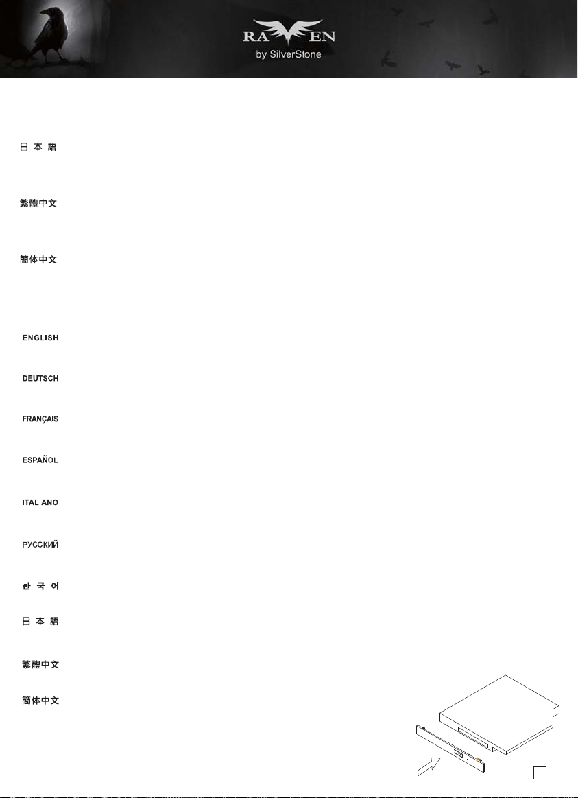
(4) Optical drive limitation
RVZ02 is compatible with only slim optical drives
For 12.7mm slim optical drive, both slot-loading or tray-loading type can be used.
For 9.5mm slim optical drive, only tray-loading type can be used and an adapter (included) is required for installation. Please refer to illustration for
install instruction.
RVZ02 ist nur mit schmalen optischen Laufwerken kompatibel
Bei einem 12,7 mm schmalen optischen Laufwerk kann sowohl die Slot-In- als auch die Schubladenvariante verwendet werden.
Bei einem 9,5 mm schmalen optischen Laufwerk wird nur die Schubladenvariante unterstützt; zur Installation ist ein Adapter (mitgeliefert) erforderlich.
Bitte beachten Sie zur Installation die Abbildung.
Le RVZ02 est uniquement compatible avec les lecteurs optiques fins
Pour les lecteurs optiques fins de 12,7 mm de type slim, un type de chargement par fente ou par plateau peut être utilisé.
Pour les lecteurs optiques fins de 9,5 mm de type slim, seul le type de chargement par plateau peut être utilisé et un adaptateur (fourni) est nécessaire
pour l'installation. Veuillez consulter l'illustration pour les instructions d'installation.
La RVZ02 es compatible solo con dispositivos ópticos delgados
Para un dispositivo óptico delgado de 12,7mm, se pueden usar los tipos de carga mediante ranura o bandeja.
Para un dispositivo óptico delgado de 9,5mm, sólo se pueden usar los tipos de carga mediante bandeja y es necesario un adaptador (incluido) para
la instalación. Por favor, consulte la ilustración para las instrucciones de instalación.
RVZ02 è compatibile solo con unità ottiche slim
Per quanto riguarda le unità slim da 12,7 mm, possono essere utilizzate sia quelle con caricamento a fessura, sia quelle con caricamento a cassetto.
Per quanto riguarda le unità slim da 9,5 mm, possono essere utilizzate solo quelle con caricamento a cassetto, e per l’installazione è necessario un
adattatore (incluso). Fare riferimento all’illustrazione per istruzioni sull'installazione.
Корпус RVZ02 совместим только с тонкими оптическими приводами
При использовании тонкого 12,7-мм оптического привода можно применять приводы как с щелевой, так и с лотковой загрузкой диска.
При использовании тонкого 9,5-мм оптического привода можно применять только приводы с лотковой загрузкой диска, при
требуется адаптер (в комплекте). Указания по установке см. на иллюстрации.
슬림형 광 드라이브만 RVZ02와 호환됩니다
12.7mm 슬림형 광 드라이브의 경우 슬롯 로딩 타입이나 트레이 로딩 타입 둘 다 사용할 수 있습니다.
9.5mm 슬림형 광 드라이브의 경우 트레이 로딩 타입만 사용할 수 있으며 설치할 때 어댑터(함께 제공된)가 필요합니다. 설치 방법은 그림을 참조하십시오.
RVZ02はスリム型光学ドライブとのみ互換性を有します
12.7mmスリム型光学ドライブでは、スロットローディングとトレイローディングの双方のタイプが利用可能です。
9.5mmスリム型光学ドライブでは、トレイローディングタイプのみが使用可能で、装着にはアダプタ(付属)が必要です。装着の手順はイラストをご参照
ください。
RVZ02只能使用薄型光碟機
如果光碟機厚度為12.7mm,可選擇使用托盤式光碟機或吸入式光碟機
如果光碟機厚度為9.5mm,則必須使用附件的轉換檔片進行安裝,並且只能使用托盤式光碟機,組裝方式如圖
RVZ02只能使用薄型光驱
如果光驱厚度为12.7mm,可选择使用托盘式光驱或吸入式光驱
如果光驱厚度为9.5mm,则必须使用附件的转换文件片进行安装,并且只能使用托盘式光驱,组装方式如图
этом для установки
20
Page 22

Optimal Thermal Performance Layout
(1)To improve cooling performance for CPU, we recommend coolers such as SilverStone’s AR06. Because the case is designed for passive cooling,
the closer the CPU fan can be to the side panel vents, the better.
(2)Expansion card area is also passively vented so we recommend graphics cards with open air cooler for best cooling performance.
(1)Zur Verbesserung der Kühlleistung für die CPU empfehlen wie Kühler, wie SilverStones AR06. Da das Gehäuse für passive Kühlung ausgelegt ist,
sollte der CPU-Kühler möglichst nah an den Belüftungsöffnungen der Seitenblende platziert werden.
(2)Der Erweiterungskartenbereich wird ebenfalls passiv gekühlt; daher empfehlen wir für optimale Kühlleistung Grafikkarten mit offenem Luftkühler.
(1)Pour améliorer les performances de refroidissement du CPU, nous recommandons des refroidisseurs tels que l'AR06 de SilverStone. Dans la mesure
où le boîtier est conçu pour un refroidissement passif, mieux vaut positionner le ventilateur du CPU au plus près des aérations des panneaux latéraux.
(2)La zone de la carte d'extension est également ventilée de manière passive, nous vous conseillons donc les cartes graphiques avec un refroidisseur
d'air ouvert pour les meilleures performances de refroidissement.
(1)Para mejorar el rendimiento de refrigeración de la CPU, le recomendamos disipadores como el SilverStone AR06. Ya que la carcasa está diseñada
para una refrigeración pasiva, mientras más cerca esté el ventilador de la CPU de las aberturas del panel lateral, mejor.
(2)La zona de la tarjeta de expansión también se ventila de forma pasiva, por lo que le recomendamos tarjetas gráficas con disipadores de aire abiertos
para un mejor rendimiento de la refrigeración.
(1)Per migliorare le prestazioni di raffreddamento della CPU, si raccomanda l’uso di dissipatori come AR06 SilverStone. Poiché il case è stato progettato
per il raffreddamento passivo, più vicina la ventola della CPU è alle prese d'aria del pannello laterale, meglio è.
(2)Anche l’area della scheda di espansione è raffreddata passivamente, quindi si consiglia l’uso di schede grafiche con raffreddamento ad aria per
ottenere le migliori prestazioni di raffreddamento.
(1)Для улучшения охлаждения процессора рекомендуется применять такие вентиляторы, как AR06 компании SilverStone. Так как конструкция
корпуса рассчитана на пассивное охлаждение, то, чем ближе к вентиляционным отверстиям размещен вентилятор процессора, тем лучше его
охлаждение.
(2)Зона размещения карты расширения также охлаждается пассивным образом, поэтому для
рекомендуется применять графические карты с открытым воздушным охлаждением.
получения наилучших характеристик охлаждения
(1)CPU의 냉각 성능을 향상시키려면 SilverStone의 AR06 모델과 같은 쿨러를 추천합니다. 케이스는 자연 냉각 방식으로 설계되었기 때문에 CPU
팬이 측면 패널 통풍구에 가까이 있을수록 냉각 성능이 향상됩니다.
(2)확장 카드 영역도 자연적으로 통풍되므로 최상의 냉각 성능을 얻으려면 개방된 기냉식 쿨러가 탑재된 그래픽 카드를 사용할 것을 권장합니다.
(1)CPUの冷却性能改善には、SilverStone製AR06などのクーラーをお勧めします。これは、ケースが受動冷却用に設計され、CPUファンが側面パネル
に近いほど良い効果が得られるためです。
(2)拡張カードエリアも受動換気なので、最善の冷却性能には開放型空冷クーラー付きグラフィックスカードをお勧めします。
(1)若需提升散熱效能,CPU散熱器建議使用銀欣AR06,由於設計為被動式散熱,Cooler風扇與側板距離越緊貼,散熱效果越佳
(2)顯示卡區域也是依靠被動進風的方式進行散熱,如欲安裝高階顯示卡,建議選擇顯示卡散熱器型式為開放型的散熱效果最佳
(1)若需提升散热效能,CPU散热器建议使用银欣AR06,由于设计为被动式散热,Cooler风扇与侧板距离越紧贴,散热效果越佳
(2)显示卡区域也是依靠被动进风的方式进行散热,如欲安装高阶显示卡,建议选择显示显示卡型式为开放型的散热效果最佳
21
Page 23

Optimal Thermal Performance Layout
(3) Vertical/horizontal placement
Because most vents are situated on the bottom, placing the RVZ02 vertically will result in better temperature than in horizontal position.
When using the case horizontally, please be sure of adhering rubber stands to the bottom.
Da sich die meisten Belüftungsöffnungen an der Unterseite befinden, führt die vertikale Aufstellung des RVZ02 zu einem besseren Temperaturergebnis
als die horizontale Aufstellung.
Wenn Sie das Gehäuse horizontal verwenden, denken Sie bitte daran, die Gummifüße an der Unterseite anzubringen.
Parce que la plupart des sorties sont situées en bas, le fait de placer le RVZ01 verticalement permettra d'obtenir une meilleure température que dans
la position horizontale.
Lorsque vous utilisez le boîtier horizontalement, veuillez vous assurer d'installer les pieds de caoutchouc en bas.
Ya que la mayoría de las aberturas están situadas en la parte inferior, situar la FTZ01 verticalmente provocará que la temperatura sea mejor que en
posición horizontal.
Cuando use la carcasa horizontalmente, por favor asegúrese de adherir las patas de goma a la parte inferior.
Poiché la maggior parte delle prese d’aria è situata sulla parte inferiore, collocando RVZ02 in verticale la temperatura sarà migliore che in posizione
orizzontale.
Quando si utilizza il case in orizzontale, assicurarsi di fare aderire i supporti di gomma sulla parte inferiore.
Так как большинство вентиляционных отверстий находятся на нижней панели корпуса, установка RVZ02 в вертикальном положении приводит
к лучшим результатам по сравнению с горизонтальной установкой.
При горизонтальном размещении закрепите на дне самоклеящиеся резиновые стойки.
대부분의 통풍구는 바닥에 위치하기 때문에 RVZ02을 수직으로 배치할 경우 수평 위치보다 온도를 낮출 수 있습니다.
케이스를 수평으로 사용할 경우 바닥에 고무 스탠드를 부착하십시오.
大部分の換気口が底に位置しているので、RVZ02を垂直設置した方が水平位置設置より理想的な温度になります。
水平設置の場合、ゴムスタンドを底部に貼付したことをご確認ください。
由於底層通風性的限制,散熱方面,將RVZ02直立使用的整體溫度會低於橫躺使用的溫度
橫躺使用時請記得貼上腳墊
由于底层通风性的限制,散热方面,将RVZ02直立使用的整体温度会低于横躺使用的温度
横躺使用时请记得贴上脚垫
22
Page 24

Optimal Thermal Performance Layout
(4) Cable routing
The photo shows recommended cable routing paths
Die Abbildung zeigt die empfohlenen Kabelwege
La photo montre les chemins de passage de câbles recommandés
La foto muestra los caminos de enrutado recomendados para los cables.
La foto mostra il cablaggio raccomandato per i cavi
На фотографии показан рекомендуемый способ прокладки кабелей
이 사진에는 권장되는 케이블 라우팅 경로가 나와있습니다
写真には推奨されるケーブル取り回しが示されています。
圖示為示範的整線圖
图示为示范的整线图
23
Page 25

Filter removal (RVZ02B)
As shown in illustration, filters on both sides can be removed for cleaning.
(applicable to “window-less” SST-RVZ02B only)
Wie in der Abbildung gezeigt, können die Filter an beiden Seiten zur Reinigung entfernt werden.
(nur beim „fensterlosen“ SST-RVZ02B)
Comme indiqué dans l'illustration, les filtres des deux côtés peuvent être retirés pour le nettoyage.
(applicable uniquement au SST-RVZ02B « sans fenêtre »)
Como se muestra en la ilustración, los filtros a ambos lados se pueden sacar para su limpieza.
(aplicable solo a la SST-RVZ02B “sin ventanas”)
Come mostrato nell’illustrazione, i filtri su entrambi i lati possono essere rimossi per la pulizia.
(applicabile solo per SST-RVZ02B "senza finestra")
Как видно из иллюстрации, фильтры с обеих сторон можно извлечь для очистки.
(только для «безоконной» модели SST-RVZ02B)
그림에 나와있는 것과 같이 양쪽에 있는 필터를 빼서 세척할 수 있습니다.
(“창 없는” SST-RVZ02B 모델에만 적용됨)
図に示されるように、フィルターの両側がクリーニング時に取り外せます。
(「ウィンドウなし」SST-RVZ02Bにのみ適用)
如圖示,可直接移除兩側濾網進行清理
(僅SST-RVZ02B無開窗版本)
如图示,可直接移除两侧滤网进行清理
(仅SST-RVZ02B无开窗版本)
24
Page 26

Protect Your Computer
A lock and cable can be purchased on the market for use with the Kensington security slot located on rear of RVZ02 to prevent removal of
the entire computer or top cover.
Caution: Please check for compatibility before purchasing the lock and cable for use with RVZ02’s Kensington security slot.
Im Fachhandel erhalten Sie passende Schlösser und Kabel zum Anschluss an den Kensington-Sicherheitsschlitz; auf diese Weise können
Sie verhindern, dass der gesamte Computer gestohlen wird oder die Seitenwände abgenommen werden.
Achtung: Bitte erkundigen Sie sich zuvor, ob Schlösser und Kabel zu den Kensington-Sicherheitsschlitzen des RVZ02 passen.
Un câble de verrouillage peut être acheté pour utilisé l'emplacement de sécurité Kensington situé à l'arrière du RVZ02 pour empêcher le
boîtier d'être déplacé ou ouvert.
Attention : Veuillez vérifier la compatibilité avant d'acheter le verrou et le câble pour l'utiliser avec l'emplacement de sécurité Kensington
du RVZ02.
Se puede comprar una cerradura y un cable en el mercado para usarlos en los zócalos para seguridad Kensington situados en la parte
trasera de la RVZ02 para evitar abrir todo el ordenador o los paneles laterales.
Advertencia: Compruebe por favor la compatibilidad antes de comprar la cerradura y el cable para usarlos con los zócalos de seguridad
Kensington de la RVZ02.
Cavo e dispositivo di blocco possono essere acquistati separatamente per l’utilizzo con la fessura Kensington security posta dietro al RVZ02
per prevenire la rimozione del computer o dei pannelli laterali.
Attenzione: Controllare che cavo e dispositivo di blocco siano compatibili con la fessura Kensington security presente sul RVZ02.
В продаже имеются замки и тросы, используемые с разъемами для защитных замков защитного замка Kensington, расположенными
на задней панели корпуса RVZ02, в целях предотвращения кражи всего компьютера и снятия боковых панелей.
Внимание! Перед приобретением замков и тросов под разъемы для защитных замков Kensington корпуса RVZ02 убедитесь в их
совместимости.
켄싱턴 보안 슬롯에 사용할 수 있는 자물쇠와 케이블은 별도로 구입 하실 수 있으며, RVZ02의 뒤쪽을 잠그므로, 컴퓨터 전체의 사이드 패널을 제거
할 수 없게 해 줍니다.
주의: RVZ02용 켄싱터 보안 잠금 장치를 구입하기전에 호환성을 확인하시기 바랍니다.
RVZ02後部に配置されたケンジントンセキュリティスロットに合ったロックとケーブルは市場で購入でき、コンピュータ全体またはパネルの盗難を
防止するのに使用できます。
注意:RVZ02のケンジントンセキュリティスロットに使用するロックとケーブルを購入する前に、互換性をチェックしてください。
安全纜線鎖是從市面上可以買到的防盜裝置。若要使用該鎖,請將其連接至您的RVZ02上的安兩個全纜線孔。可以避免整台電腦被搬走,同時保護左右
側板避免被開啟
注意事項:購買防盜裝置之前,請確定它適用於您電腦上的安全纜線孔。
安全缆线锁是从市面上可以买到的防盗装置。若要使用该锁,请将其连接至您的RVZ02上的安两个全缆线孔。可以避免整台计算机被搬走,同时保护左
右侧板避免被开启
注意事项:购买防盗装置之前,请确定它适用于您计算机上的安全缆线孔。
25
Page 27

Q&A
Q: Does RVZ02 fit in the Sugo Pack?
A: Yes it does, with room to spare!
F: Passt das RVZ02 in das Sugo Pack?
A: Ja, es passt, es bleibt sogar noch Platz übrig!
Q: Le RVZ02 convient-il au Sugo Pack?
R: Oui, avec en plus de la place!
P : ¿Encaja la RVZ01 en el Pack Sugo?
R : ¡Pues sí, con espacio de sobra!
D: RVZ02 entra nel Sugo Pack?
R: Sì. E rimane altro spazio!
Вопрос: Корпус RVZ02 вмещается в сумку Sugo?
Ответ: Да, и еще остается свободное место!
Q: RVZ02가 Sugo Pack에 맞습니까?
A: 예, 맞습니다. 그리고 여분의 공간이 있습니다!
Q. RVZ02は、Sugoパックに入りますか?
A. はい、余裕で入ります!
Q: RVZ02相容於Sugo pack嗎?
A: 相容
Q: RVZ02相容于Sugo pack吗?
A: 相容
26
Page 28
Q&A
Q: Everything is properly installed, why does it not start up?
A: If your PSU has an AC switch, make sure the switch is at the “ON” position.
F: Alles ist richtig installiert; warum läuft mein System nicht an?
A: Wenn Ihr Netzteil mit einem Schalter ausgestattet ist, vergewissern Sie sich, dass sich dieser in der ON-Position befindet.
Q: Tout est installé correctement, pourquoi est-ce que rien ne démarre ?
R: Si votre PSU dispose d’un commutateur de CA, assurez-vous que le commutateur est en position “ON”.
P : Todo está instalado correctamente, ¿por qué no arranca el sistema?
R : Si su FA tiene un interruptor de potencia, compruebe que el interruptor está en la posición “ON”.
D: Tutto è installato correttamente, perché non si avvia?
R: Se il PSU dispone di un interruttore CA, assicurarsi che l'interruttore sia in posizione "ON"
Вопрос: Все установлено правильно, но системный блок не включается. Что делать?
Ответ: Если блок питания имеет выключатель питания, убедитесь, что он установлен в положение ON (Вкл.).
Q: 모든 것을 제대로 설치했는데 작동되지 않는 이유가 무엇입니까?
A: PSU에 AC 스위치가 있는 경우, 스위치가 “ON” 위치에 있는지 확인하십시오
Q. 全て正しくインストールされたのに、なぜ起動しませんか?
A. PSUにACスイッチがある場合、スイッチが「オン」の位置にあることを確認してください。
Q: 所有零件都安裝完成,為何無法順利開機?
A: 如果您的電源供應器帶有交流電開關,請確認開關的位置是在開啟的狀態。
Q: 所有零件都安装完成,为何无法顺利开机?
A: 如果您的电源供应器带有交流电开关,请确认开关的位置是在开启的状态。
27
Page 29

Warranty Information
This product has a limited 1 year warranty in North America and Australia.
For information on warranty periods in other regions, please contact your reseller or SilverStone authorized distributor.
Warranty terms & conditions
1. Product component defects or damages resulted from defective production is covered under warranty.
Defects or damages with the following conditions will be fixed or replaced under SilverStone Technology’s jurisdiction.
a) Usage in accordance with instructions provided in this manual, with no misuse, overuse, or other inappropriate actions.
b) Damage not caused by natural disaster (thunder, fire, earthquake, flood, salt, wind, insect, animals, etc…)
c) Product is not disassembled, modified, or fixed. Components not disassembled or replaced.
d) Warranty mark/stickers are not removed or broken.
Loss or damages resulted from conditions other than ones listed above are not covered under warranty.
2. Under warranty, SilverStone Technology’s maximum liability is limited to the current market value for the product (depreciated value, excluding
shipping, handling, and other fees). SilverStone Technology is not responsible for other damages or loss associated with the use of product.
3. Under warranty, SilverStone Technology is obligated to repair or replace its defective products. Under no circumstances will SilverStone
Technology be liable for damages in connection with the sale, purchase, or use including but not limited to loss of data, loss of business, loss of
profits, loss of use of the product or incidental or consequential damage whether or not foreseeable and whether or not based on breach of warranty,
contract or negligence, even if SilverStone Technology has been advised of the possibility of such damages.
4. Warranty covers only the original purchaser through authorized SilverStone distributors and resellers and is not transferable to a second hand
purchaser.
5. You must provide sales receipt or invoice with clear indication of purchase date to determine warranty eligibility.
6. If a problem develops during the warranty period, please contact your retailer/reseller/SilverStone authorized distributors or SilverStone
http://www.silverstonetek.com.
Please note that: (i) You must provide proof of original purchase of the product by a dated itemized receipt; (ii) You shall bear the cost of shipping
(or otherwise transporting) the product to SilverStone authorized distributors. SilverStone authorized distributors will bear the cost of shipping
(or otherwise transporting) the product back to you after completing the warranty service; (iii) Before you send the product, you must be issued a
Return Merchandise Authorization (“RMA”) number from SilverStone. Updated warranty information will be posted on SilverStone’s official website.
Please visit http://www.silverstonetek.com for the latest updates.
Additional info & contacts
For North America (usasupport@silverstonetek.com)
SilverStone T echnology in North America may repair or replace defective product with refurbished product that is not new but has been functionally tested.
Replacement product will be warranted for remainder of the warranty period or thirty days, whichever is longer. All products should be sent
back to the place of purchase if it is within 30 days of purchase, after 30 days, customers need to initiate RMA procedure with SilverStone Technology
in USA by first downloading the “USA RMA form for end-users” form from the below link and follow its instructions.
http://silverstonetek.com/contactus.php
For Australia only (support@silverstonetek.com)
Our goods come with guarantees that cannot be excluded under the Australian Consumer Law.
You are entitled to a replacement or refund for a major failure and for compensation for any other reasonably foreseeable loss or damage.
You are also entitled to have the goods repaired or replaced if the goods fail to be of acceptable quality and the failure does not amount to a major failure.
Please refer to above “Warranty terms & conditions” for further warranty details.
SilverStone Technology Co., Ltd. 12F No. 168 Jiankang Rd., Zhonghe Dist., New Taipei City 235 Taiwan R.O.C. + 886-2-8228-1238
(standard international call charges apply)
For Europe (support.eu@silverstonetek.de)
For all other regions (support@silverstonetek.com)
Page 30

Page 31

Page 32
G11224710
 Loading...