

Page 1
SST-ET750-G/SST-ET650-G/SST-ET550-G
High efficiency with 80 PLUS Gold certification
24/7 continuous power output with 40°C operating temperature
Class-leading single +12V rail
Silent running 120mm fan with 18dBA
PCIe 8pin and PCIe 6pin connectors support
All-black flat cables design
Page 2
1.0 INPUT:
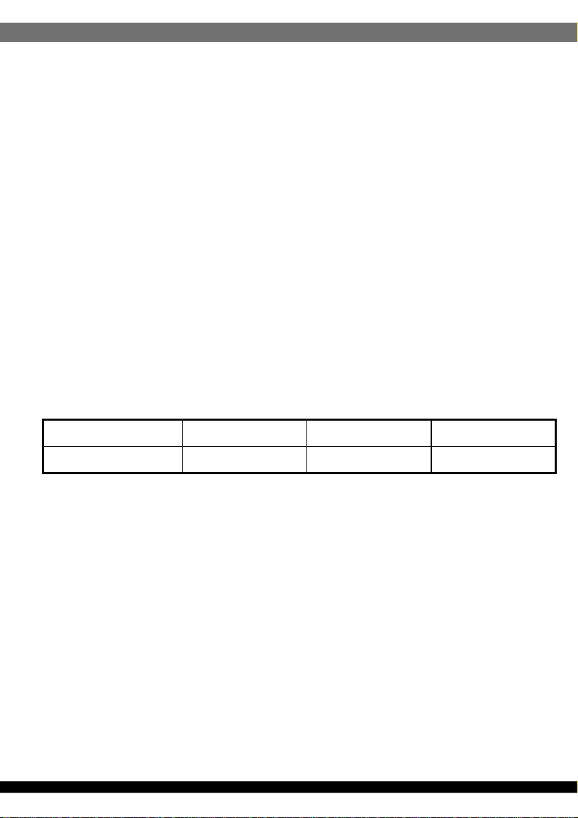
1.1 VOLTAGE
MINIMUM NOMINAL MAXIMUM UNITS
SPECIFICATION
SilverStone Essential
ET750-G
ET650-G
ET550-G
ATX12V Switching Power Supply
With Active PFC
80Plus Gold
PS/2
103 115-230 254 Vrms
1.2 FREQUENCY
47Hz ~ 63Hz
1.3 CURRENT
115Vac/10.0A max. 230Vac/5.0A max. (ET750-G, ET650-G)
115Vac/8.0A max. 230Vac/4.0A max. (ET550-G)
1.4 INRUSH CURRENT
150A max. when ac input 230Vac and 250C cold start.
1.5 POWER EFFICIENCY
Meet 80 Plus Gold requirement at 115Vac input.
1.6 LEAKAGE CURRENT
3.5mA max.
1.7 POWER FACTOR
PF > 0.96 at 230Vac input and full load
1.8 ErP REQUIREMENT
Meet ErP2013 requirement
01
Page 3
2.0 OUTPUT:
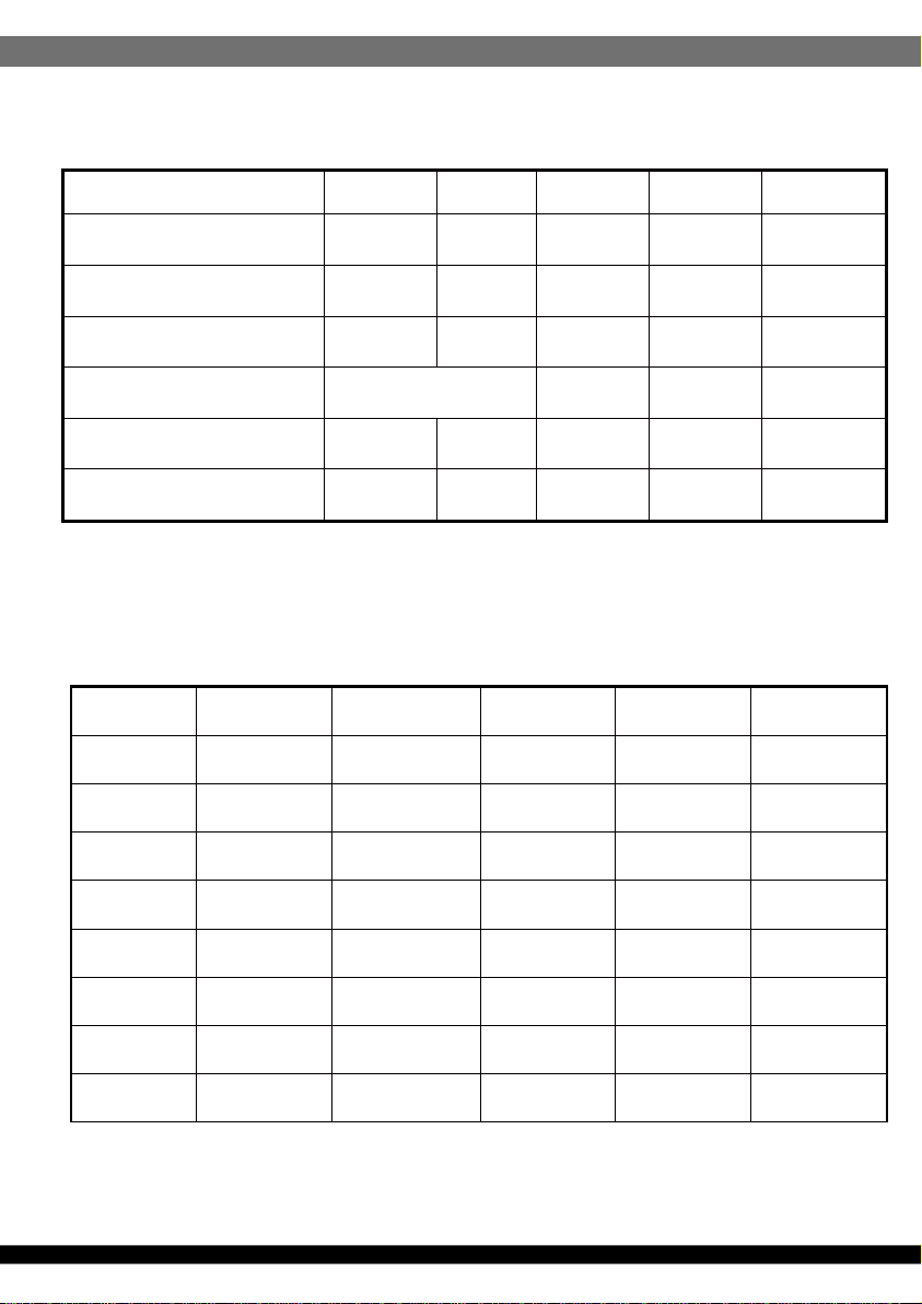
ET750-G
Voltage
Max load
*
Min load
Peak load
Combined power
*
Regulation
*
Ripple & Noise
*
* The continuous total output power is 750W max.
• The combined power of +5V and +3.3V is 120W max.
• Peak currents may last up to 12 seconds with not more than one occurrence per minute.
*
Add 0.1uF and 10uF capacitors across output terminal during ripple & noise test.
*
LOAD REGULATION TEST TABLE:
+5V +3.3V +12V -12V +5Vsb
22.0A 22.0A 62.0A 0.3A 2.5A
0.0A 0.0A 0.0A 0.0A 0.0A
-- -- -- -- 3.0A
120W -- -- --
+5,-5% +5,-5% +5,-5% +10,-10% +5,-5%
50mV 50mV 120mV 120mV 50mV
+5V +12V +3.3V -12V +5Vsb
LOAD1
LOAD2
0.0A 0.0A 0.0A 0.0A 0.0A
5.0A 0.5A 5.0A 0.1A 0.1A
LOAD3
LOAD4
LOAD5
LOAD6
LOAD7
LOAD8
10.0A 5.0A 10.0A 0.1A 0.5A
22.0A 10.0A 3.0A 0.2A 1.0A
9.5A 15.0A 22.0A 0.2A 2.5A
0.0A 62.0A 0.0A 0.3A 0.5A
12.0A 53.0A 12.0A 0.3A 2.0A
0.3A 0.3A 0.3A 0.0A 0.0A
02
Page 4

ET650-G
Voltage
Max load
*
Min load
Peak load
Combined power
*
Regulation
*
Ripple & Noise
*
* The continuous total output power is 650W max.
• The combined power of +5V and +3.3V is 110W max.
• Peak currents may last up to 12 seconds with not more than one occurrence per minute.
Add 0.1uF and 10uF capacitors across output terminal during ripple & noise test.
*
LOAD REGULATION TEST TABLE:
*
+5V +3.3V +12V -12V +5Vsb
20.0A 20.0A 53.0A 0.3A 2.5A
0.0A 0.0A 0.0A 0.0A 0.0A
-- -- -- -- 3.0A
110W -- -- --
+5,-5% +5,-5% +5,-5% +10,-10% +5,-5%
50mV 50mV 120mV 120mV 50mV
+5V +12V +3.3V -12V +5Vsb
LOAD1
LOAD2
0.0A 0.0A 0.0A 0.0A 0.0A
5.0A 0.5A 5.0A 0.1A 0.1A
03
LOAD3
LOAD4
LOAD5
LOAD6
LOAD7
LOAD8
10.0A 5.0A 10.0A 0.1A 0.5A
20.0A 10.0A 6.0A 0.2A 1.0A
11.0A 15.0A 20.0A 0.2A 2.5A
0.0A 53.0A 0.0A 0.3A 0.5A
12.0A 44.0A 12.0A 0.3A 2.0A
0.3A 0.3A 0.3A 0.0A 0.0A
Page 5

ET550-G
Voltage
Max load
*
Min load
Peak load
Combined power
*
Regulation
*
Ripple & Noise
*
* The continuous total output power is 550W max.
• The combined power of +5V and +3.3V is 110W max.
• Peak currents may last up to 12 seconds with not more than one occurrence per minute.
Add 0.1uF and 10uF capacitors across output terminal during ripple & noise test.
*
*
LOAD REGULATION TEST TABLE:
+5V +3.3V +12V -12V +5Vsb
20.0A 20.0A 45.0A 0.3A 2.5A
0.0A 0.0A 0.0A 0.0A 0.0A
-- -- -- -- 3.0A
110W -- -- --
+5,-5% +5,-5% +5,-5% +10,-10% +5,-5%
50mV 50mV 120mV 120mV 50mV
+5V +12V +3.3V -12V +5Vsb
LOAD1
LOAD2
0.0A 0.0A 0.0A 0.0A 0.0A
5.0A 0.5A 5.0A 0.1A 0.1A
LOAD3
LOAD4
LOAD5
LOAD6
LOAD7
LOAD8
2.1 REMOTE ON/OFF
TTL High/PS-OFF; TTL Low/PS-ON
VIL=0.8Vmax, IIL=-1.6mAmax @Vin=0.4V
VIH=2.0Vmin @Iin=-200uA, VIH=5.25Vmax @open ckt.
10.0A 5.0A 10.0A 0.1A 0.5A
20.0A 10.0A 3.0A 0.2A 1.0A
9.0A 15.0A 20.0A 0.2A 2.5A
0.0A 45.0A 0.0A 0.3A 0.5A
11.0A 37.0A 11.0A 0.3A 2.0A
0.3A 0.3A 0.3A 0.0A 0.0A
04
Page 6

2.2 HOLD-UP TIME
10msec (minimum) at 80% of full load at 230Vac input.
2.3 POWER GOOD DELAY
100-500 msec.
2.4 POWER FAIL DELAY
>1 msec.
2.5 TURN-ON DELAY TIME
2000 msec max.At nominal line full load.
2.6 TRANSIENT OVERSHOOT
DC output transient step sizes as below table:
Output voltage +5V +3.3V +12V
Max. step size 30% 30% 60%
Load-changing repetition rate of 10m seconds.
Load slew rated 1.0A/uS and capacitive load as below :
+5V +3.3V +12V -12V +5Vsb
10000uF 10000uF 10000uF 470uF 3300uF
2.7 RISE TIME
20ms max at full load.
3.0 PROTECTION:
When OVP ,OPP or short protection is triggered, the main outputs will be latched
off. The main outputs can be reset by cycling the DC remote on/off or AC power.
+5Vsb output is auto recovery when fault condition removed.
3.1 OVER VOLTAGE PROTECTION
+3.3V output 4.5 Vmax.
+5.0V output 7.0 Vmax.
+12.0V output 15.6 Vmax.
3.2 SHORT PROTECTION
All output to GND.
3.3 OVER POWER PROTECTION
Foldback at 110%~150% over peak load
3.4 OVER TEMPERATURE PROTECTION
05
Page 7

4.0 ENVIRONMENT:
4.1 OPERATING TEMP. 0 °C to +40 °C
4.2 STORAGE TEMP. -20 °C to +70 °C
4.3 OPERATING HUMIDITY 20% to 90%,non-condensing
4.4 STORAGE HUMIDITY 5% to 95%, non-condensing
4.5 OPERATING ALTITUDE 0 to 10,000 feet
4.6 STORAGE ALTITUDE 0 to 50,000 feet
5.0 HI-POT:
5.1 PRIMARY TO SECONDARY
1800Vac for 1 minute
6.0 SAFETY AND EMC REQUIREMENTS
6.1 CONDUCTED EMI
1.MEET FCC:Class B
2.MEET BSMI:Class B
3. MEET CISPR 22: Class B
6.2 SAFETY STANDARDS
1.MEET CUL(UL60950)
2. MEET TUV (EN60950)
3. MEET CB (IEC 950 )
4. MEET CE
5. MEET CCC
6.3 HARMONIC
MEET IEC61000-3-2,Class D
7.0 MTBF at 25°C(demonstrated)
100K hrs minimum
8.0 DIMENSIONS
W x Lx H=150mm x 140mm x 86mm
06
Page 8

NO. G11231630
 Loading...