

Page 1
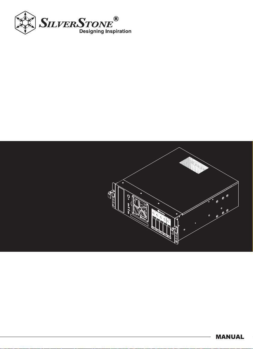
Case Storage
4U 5-bay 3.5" hot-swappable storage chassis
CS350
Page 2
Installation and system optimization guide:
The following manual and guides were carefully prepared by the SilverStone engineering team to
help you maximize the potential of your SilverStone product. Please keep this manual for future
reference when upgrading or performing maintenance on your system. A copy of this manual can also
be downloaded from our website at:
Product Overview
Special Features
Specification
Disassemble Chart
Exterior Overview
Installation Guide
How to install 5.25" device?
How to install slim optical drive?
How do I adjust the expansion slot brace?
Connector Definition
Component Size Limitations
Warranty Information
P.1
P.1
P.1
P.2
P.3
P.5
P.14
P.17
P.20
P.23
P.26
Page 3
Product Overview
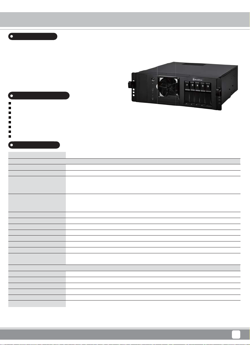
Introduction
To fulfill the needs of enthusiasts looking for a versatile desktop or server chassis,
SilverStone designed the CS350. Its modern front panel design can support
five hot-swappable 3.5" SAS / SATA HDD comfortably with individual LED
indicators allowing for easy and quick drive status monitoring in one glance.
For extra security, each drive tray also has metal key lock. Besides easily
fitting ATX or Micro-ATX motherboard, the CS350 is loaded with features such
as 120mm fan, magnetic fan filter, and designs for efficient use in server rack
with optional tool-less rail slide*. With an overall package designed for maximizing
efficiency, flexibility, and durability, the CS350 is a great choice for professionals
or data center engineers looking to build a storage server.
Special Features
Magnetic fan filter included for easy maintenance against dust
Supports graphics cards up to 13.78" (350mm)
Supports ATX, Micro-ATX motherboards
Support standard PS2 (ATX) up to 250mm
Support five 3.5" SAS / SATA 6 Gbit/s drives with trayless & screwless design
Adjustable drive status LED and fan control system
Individual metal key lock for each drive for extra security
Full support for SATA hot-swap
Specification
Model No.
Material
Color
Motherboard
Drive Bay
Cooling System
Expansion Slot
Front I/O Port
Power Supply
Expansion Card
Limitation of CPU cooler
Limitation of PSU
Net weight
Dimension
Hot Swap 3.5" HDD Storage
Transfer rate
Host interface
Power connector
Drive tray security
LED indicator
Switch button
* Your system must have SAS controller if you want to use SAS HDD
** Hard drive capacity and RAID support is dependent on SAS or SATA controller used
*** Compatible with tool-less rail slide - RMS05-22
**** If you want to install CS350 into a rack, we highly recommended removing its foot stands first
SST-CS350
SECC body
Black
ATX, Micro-ATX
External
Internal
Front
Internal
Rear
7+1
USB 3.0 x 2, Audio x 1, MIC x 1
Support standard PS2 (ATX) up to 250mm
Support graphics card up to 13.78" (350mm), width restriction - 4.52" (114mm)
110mm
250mm
7.95kg
440mm (W) x 161.2mm (H) x 474mm (D)
17.32" (W) x 6.35" (H) x 18.66" (D)
Up to 6 Gbit/s (dependent on drive speed)
7pin SATA connector x 5 or SAS* primary channel connection
SATA 15pin x 2
Triangle metal key lock design
Power ON: Blue, Accessing: Purple blinking
Fan speed: High / Low, HDD LED: ON / OFF
5.25" x 1, 12.7mm slim optical x 1
3.5" x 5 hot-swappable
2.5" x 2 (Support up to 9.5mm), 3.5" x 1
120mm fan x 1
80mm fan x 1, 3000rpm (on hot-swap cage)
70mm fan slot x 2
Case Storage CS350
1
Page 4
Case Storage CS350
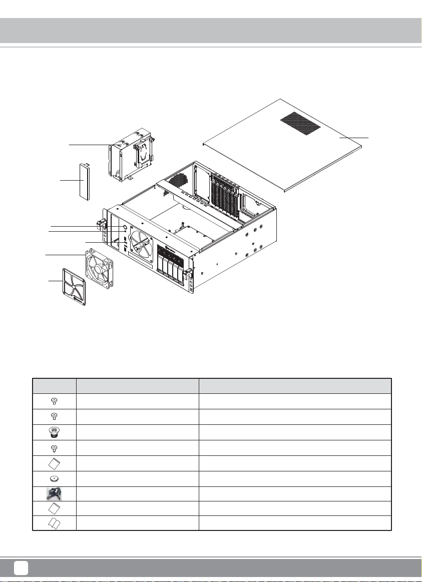
Disassemble Chart
5.25" DRIVE CAGE
5.25" BRACKET
POWER SW
RESET SW
USB 3.0 X 2 + SPK + MIC
12025 FAN
FAN FIL TER
PICTURE PURPOSEITEM
SCREW-P-HEAD-M4-4
SCREW-I-6-32 X 5-BK
SCREW-M3-4
SCW-M2 X 3
ASSEMBLY
FFG-2A (RU)
KEY
PLASTIC BAG
MANUAL
TOP COVER
SCREW FOR FOOT PAD
SCREW FOR PSU, M/B, HDD
SCREW FOR 5.25" DRIVE BAY
SCREW FOR 12.5mm/9.5mm ODD
SCREW FOR RAIL SLIDE (OPTIONAL)
FOOT PAD
LOCKER
CS350 MANUAL
2
Page 5
Case Storage CS350
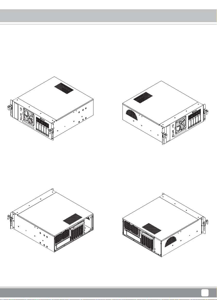
Exterior Overview
Left front 3/4 view
Left rear 3/4 view
Right front 3/4 view
Right rear 3/4 view
3
Page 6
Case Storage CS350
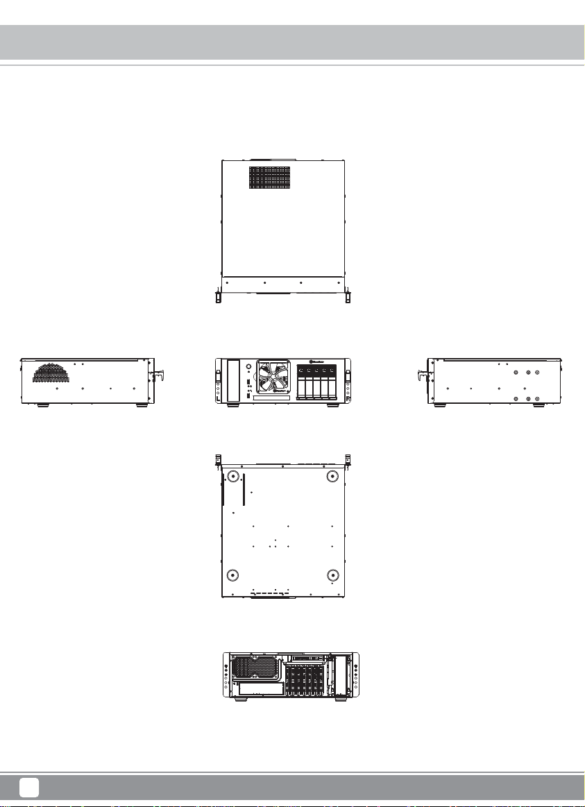
Exterior Overview
Top
Middle RightLeft
Bottom
Rear
4
Page 7
Installation guide
Before you begin, please make sure that you
1
have all components collected
2
check that all components do not have compatibility problems with each other or with the case
3
if possible, assemble the components outside the case first to make sure they are working
keep the motherboard manual ready for reference during installation
4
prepare a Philips screwdriver
5
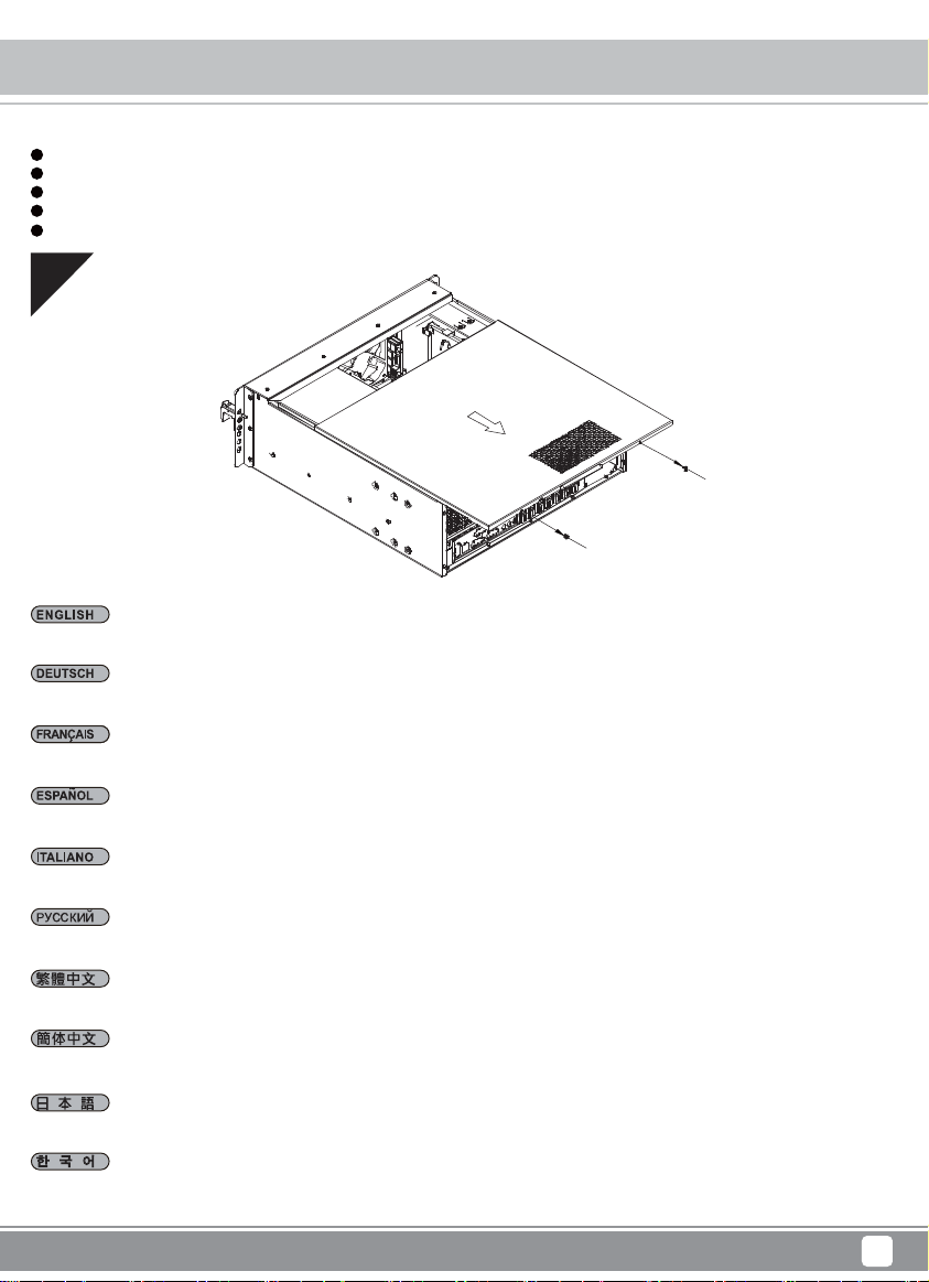
01
Remove screws on both sides of the case and remove top cover in direction shown in the illustration
Case Storage CS350
Entfernen Sie die Schrauben an beiden Seiten des Gehäuses und entfernen Sie dann die obere Abdeckung in der abgebildeten Ausrichtung
Retirez les vis des deux côtés du boîtier et retirez le couvercle supérieur dans la direction indiquée dans l'illustration
Quite los tornillos de ambos lados de la carcasa y retire la cubierta superior en la dirección que se muestra en la ilustración
Rimuovere le viti su entrambi i lati del case e rimuovere il coperchio superiore nella direzione mostrata nell'illustrazione
Удалите винты с обеих сторон корпуса и снимите верхнюю крышку в направлении, показанном на рисунке
取下機殼兩側螺絲,並按照圖中所示方向拆下上蓋
取下机箱两侧螺丝,并按照图中所示方向拆下上盖
ケース両側のネジを外し、図に示される方向に上部カバーを取り外します
케이스 양쪽의 나사를 제거하고 그림에 표시된 방향으로 상단 덮개를 분리합니다`
5
Page 8
Case Storage CS350
Installation guide
02
Install memory, CPU cooler, and connect SATA cables onto the motherboard first. Then install motherboard in direction shown in the illustration and
connect front I/O, fan cable and power supply connectors to it
Installieren Sie zunächst Arbeitsspeicher und CPU-Kühler und schließen Sie die SATA-Kabel am Motherboard an. Installieren Sie nun das Motherboard
in der abgebildeten Ausrichtung und verbinden Sie die vorderen Ein-/Ausgänge, Lüfterkabel und Stromanschlüsse mit ihm
Installez d'abord la mémoire, le dispositif de refroidissement du processeur et connectez les câbles SATA sur la carte mère. Puis installez la carte
mère dans la direction indiquée dans l'illustration et connectez-y les connecteurs d'E/S avant, du câble du ventilateur et de l'alimentation électrique
Instale la memoria, disipador de CPU y conecte primero los cables SATA a la placa base. Luego instale la placa base en la dirección que se muestra
en la ilustración y conecte la E/S frontal, cable de ventilador y los conectores de la fuente de alimentación
Per prima cosa, installare memoria, dispositivo di raffreddamento CPU e collegare i cavi SATA sulla scheda madre. Quindi installare la scheda madre
nella direzione mostrata nell'illustrazione e collegare i connettori I/O anteriori, il cavo della ventola e l'alimentazione
Установите память, процессорный кулер и подключите все кабели на материнской плате. Затем установите материнскую плату как показано
на рисунке и подключите фронтальные разъёмы I/O, кабели вентилятора и коннекторы питания к нему
將記憶體、CPU散熱器、SATA線,先安裝並連接至主機板,然後按照圖中所示方向安裝主機板,並連接前置I/O線材、風扇線及電源線
将内存、CPU散热器、SATA线,先安装并连接至主板,然后按照图中所示方向安装主板,并连接前置I/O线材、风扇线及电源线
まず、メモリー、CPUクーラーをインストールし、マザーボードにSATAケーブルを接続します。それから図に示される向きにマザーボードをインス
トールし、フロントI/O、ファンケーブルおよび電源コネクタを接続します
먼저 메인보드에 메모리, CPU 쿨러를 설치하고, SATA 케이블을 연결합니다. 그런 다음 그림에 표시된 방향으로 메인보드를 설치하고, 전면 I/O,
팬 케이블 및 전원 공급장치 커넥터를 메인보드에 연결합니다
6
Page 9
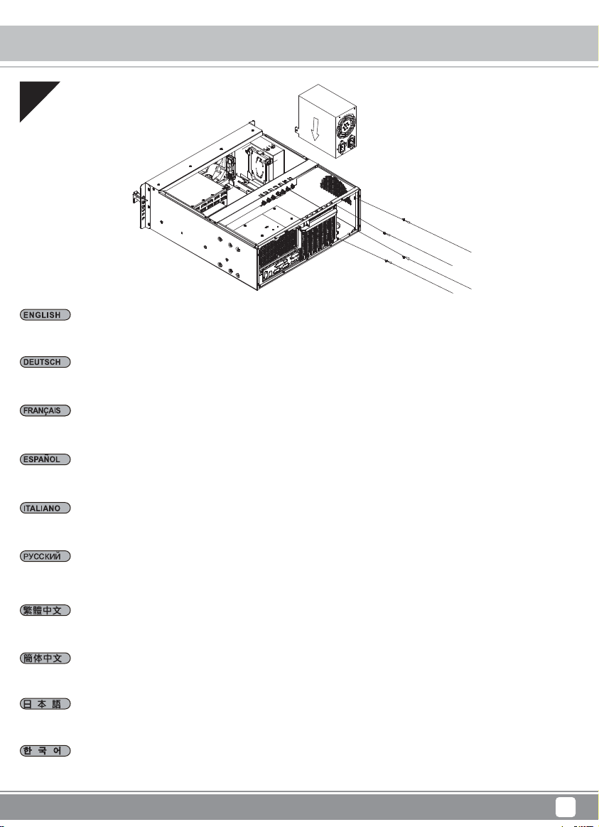
03
Install power supply in the direction as shown
Installieren Sie das Netzteil in der abgebildeten Ausrichtung
Installez l'alimentation électrique dans la direction indiquée
Case Storage CS350
Installation guide
Instale la fuente de alimentación en la dirección que se muestra
Installare l'alimentatore nella direzione mostrata
Установите блок питания как показано на рисунке
按照圖中所示方向安裝電源
按照图中所示方向安装电源
図示される向きに電源をインストールします
그림과 같은 방향으로 전원 공급장치를 설치합니다
7
Page 10
Case Storage CS350
Installation guide
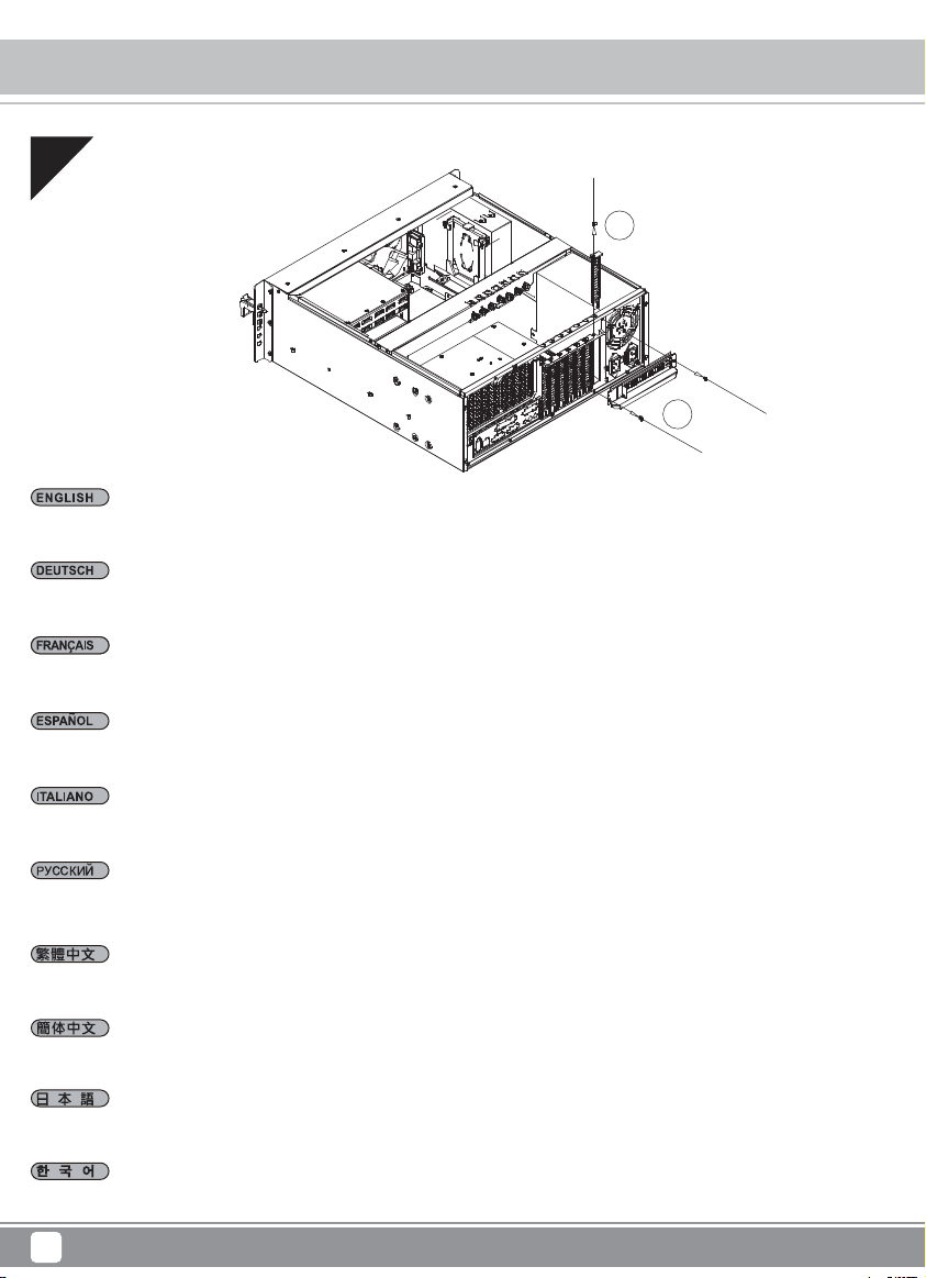
04
2
Remove expansion slot screws to remove expansion slot covers and cover plate
Entfernen Sie die Erweiterungssteckplatzabdeckungen und die Abdeckplatte, indem Sie die Schrauben lösen
1
Retirez les vis de l'emplacement d'extension pour retirer les couvercles de l'emplacement d'extension et la plaque du couvercle
Retire los tornillos del zócalo de expansión para quitar las cubiertas de los zócalos de expansión y la placa de la cubierta
Rimuovere le viti dell'alloggio di espansione per rimuuovere i coperchi degli alloggi di espansione e la relativa piastra
Удалите винты слота расширения, чтобы снять заглушки
請將擴充槽的螺絲卸下,再將擴充槽檔片及鎖固檔片卸下
请将扩展槽的螺丝卸下,再将扩展槽档片及锁固档片卸下
拡張スロットのネジを外して拡張スロットカバーおよびカバープレートを取り外します
확장 슬롯 나사를 제거하여 확장 슬롯 커버와 커버 플레이트를 분리합니다
8
Page 11

Case Storage CS350
Installation guide
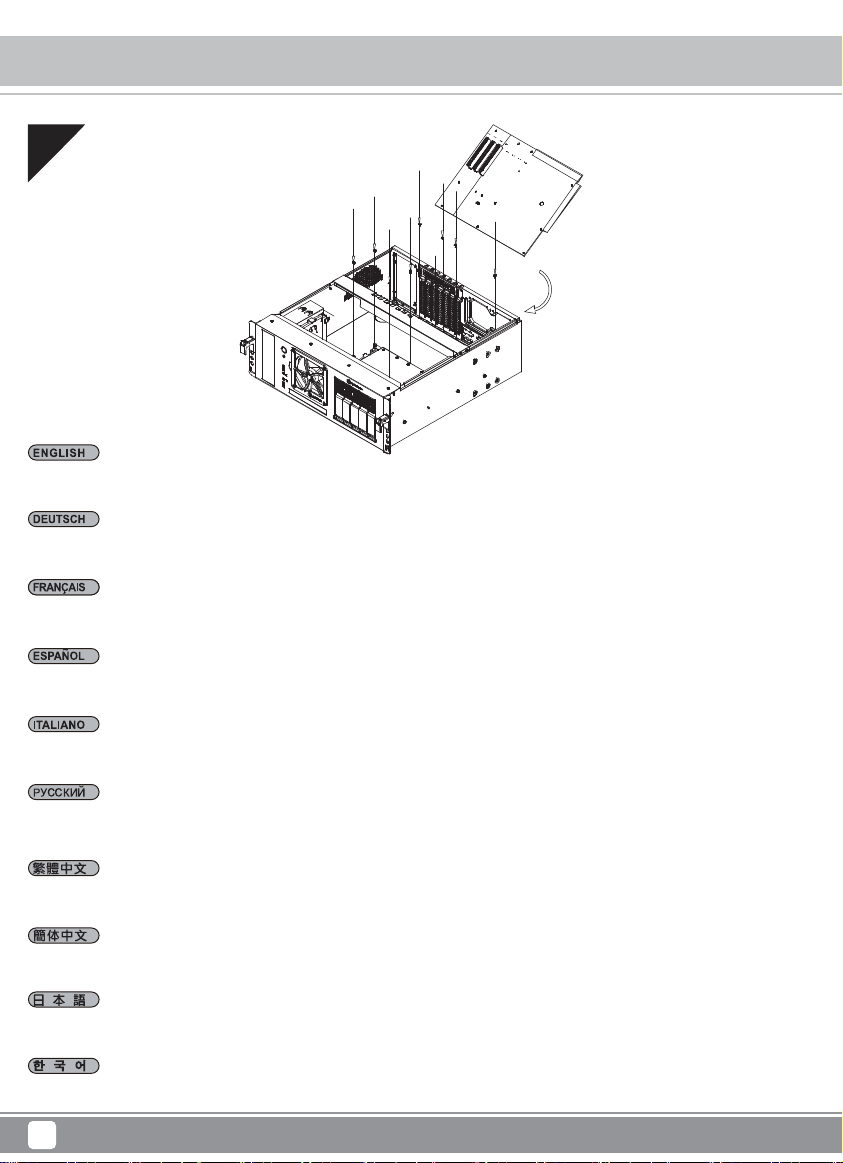
05
Install your graphic or expansion card (please install the cards in direction shown in the illustration)
Installieren Sie Ihre Grafik- oder Erweiterungskarte (bitte installieren Sie die Karten in der abgebildeten Ausrichtung)
Installez votre carte graphique ou votre carte d'extension (veuillez installer les cartes dans la direction indiquée dans l'illustration)
Instale su tarjeta gráfica o de expansión (por favor, instale las tarjetas en la dirección que se muestra en la ilustración)
Installare la scheda video o la scheda di espansione (installare le schede nella direzione mostrata nell'illustrazione)
Установите графические карты или другие карты расширения (пожалуйста, устанавливайте карты в направлении, показанном на рисунке)
安裝您的顯示卡或擴充卡 (請按照圖中所示方向安裝顯示卡及其他擴充卡)
安装您的显示卡或扩充卡 (请按照图中所示方向安装显示卡及其他扩充卡)
グラフィックスまたは拡張カードをインストールします(カードは、図に示される方向にインストールしてください)
그래픽 카드 또는 확장 카드를 설치합니다 (그림에 표시된 방향으로 카드를 설치하십시오)
9
Page 12

Case Storage CS350
Installation guide
06
Secure cards using the adjustable card braces from top support bar, then reinstall expansion slot cover plate and secure with screws
Befestigen Sie die Karten mit den einstellbaren Kartenklammern von der oberen Leiste; bringen Sie dann die Erweiterungssteckplatz-Abdeckplatte
wieder an und befestigen Sie sie mit Schrauben
Fixez les cartes avec les attaches de carte réglables depuis la barre de support supérieure, puis réinstallez la plaque du couvercle de l'emplacement
d'extension et fixez-la avec des vis
Asegure las tarjetas usando las abrazaderas para tarjetas ajustables desde la barra de soporte superior, luego reinstale la placa del zócalo de
expansión y fíjela con tornillos
Fissare le schede con i supporti regolabili della scheda dalla barra di supporto superiore, quindi reinstallare la piastra del coperchio dell'alloggio di
espansione e fissare con viti
Закрепите карты с помощью специальных скоб для карт расширения, а затем установите защитные крышки на слот расширения и закрепите
их с помощью винтов
使用機殼上方的可調整卡條固定卡,然後重新安裝擴充槽檔片並以螺絲固定
使用机箱上方的可调整卡条固定卡,然后重新安装扩展槽档片并以螺丝固定
カードは上部サポートバーからの可変カードブレースで固定してから、拡張スロットカバー・プレートを戻してネジで固定します
상단 지지 바에서 조정 가능한 카드 브레이스를 사용하여 카드를 고정한 후 확장 슬롯 커버 플레이트를 다시 설치하고 나사로 고정합니다
10
Page 13

Case Storage CS350
Installation guide
07
Install internal 2.5" drive into the tool-less drive tray and install 3.5" drive onto the 3.5” mounting holes on the side of the case (if required)
Installieren Sie das interne 2,5-Zoll-Laufwerk in dem Laufwerkeinsatz (erfordert kein Werkzeug) und installieren Sie das 3,5-Zoll-Laufwerk an den
3,5-Zoll-Montagelöchern an der Seite des Gehäuses (falls erforderlich)
Installez le lecteur 2,5" interne dans le plateau de lecteur sans outil et installez le lecteur 3,5" sur les trous de montage 3,5" sur le côté du boîtier
(si nécessaire)
Instale el dispositivo interno de 2,5" en la bandeja para dispositivos sin herramientas e instale el dispositivo de 3,5" en los agujeros de montaje del
lado de la carcasa (si es necesario)
Installare l'unità interna da 2,5" nel cassetto ad incastro e installare l'unità da 3,5" nei fori di montaggio da 3,5" sul lato del case (se necessario)
Установите накопитель 2,5" в соответствующий лоток, а накопитель 3,5" установите на монтажные отверстия на боковой стороне корпуса
(если это требуется)
安裝內接2.5"硬碟於免螺絲硬碟架及安裝3.5"硬碟於硬碟鎖固孔 (如果需要的話)
安装内接2.5"硬盘于免螺丝硬盘架及安装3.5"硬盘于硬盘锁固孔 (如果需要的话)
内部2.5"ドライブはツール不要ドライブトレイにインストールし、3.5"ドライブはケース側面の3.5"マウント孔に装着します(必要時)
내부 2.5" 드라이브를 툴리스 드라이브 트레이에 설치하고 3.5" 드라이브를 케이스 측면의 3.5" 장착 구멍에 설치합니다(필요한 경우)
11
Page 14

Case Storage CS350
Installation guide
08
Install 3.5" drive into the hot-swap tray and lock it with included key if needed
Installieren Sie das 3,5-Zoll-Laufwerk im Hot-Swapping-Einsatz und schließen Sie diesen bei Bedarf mit dem beigefügten Schlüssel ab
Installez le lecteur 3,5" dans le plateau échangeable à chaud et verrouillez-le avec la clé incluse si nécessaire
Instale el dispositivo de 3,5" en la bandeja de cambio en caliente y fíjelo con la llave incluida si es necesario
Installare l'unità da 3,5" nell'unità hot-swap e bloccarla con la chiave inclusa, ove necessario
Установите диски 3,5" в лоток с возможностью горячей замены и зафиксируйте его с помощью прилагаемого ключа (если это требуется)
安裝3.5"硬碟於熱插拔硬碟模組,並用鎖匙鎖上
安装3.5"硬盘于热插拔硬盘模块,并用锁匙锁上
3.5"ドライブをホットスワップ対応トレイにインストールし、必要であれば付属のキーでロックします
3.5" 드라이브를 핫스왑 트레이에 설치하고, 필요한 경우 제공된 키를 사용하여 이를 잠급니다
12
Page 15

Case Storage CS350
Installation guide
09
Make sure all cables are connected correctly then reinstall top cover to complete installation
Stellen Sie sicher, dass alle Kabel richtig angeschlossen sind. Bringen Sie dann zum Abschließen der Installation die obere Abdeckung wieder an
Assurez-vous que tous les câbles sont connectés correctement puis réinstallez le couvercle supérieur pour terminer l'installation
Asegúrese de que todos los cables están conectados correctamente y luego reinstale la cubierta superior para completar la instalación
Assicurarsi che tutti i cavi siano collegati correttamente, quindi reinstallare il coperchio superiore per completare l'installazione
Убедитесь, что все кабели подключены правильно, установите верхнюю крышку, чтобы завершить настройку
確認所有線材均已正確的連接上,然後重新裝回頂蓋,完成安裝
确认所有线材均已正确的连接上,然后重新装回顶盖,完成安装
全てのケーブルが正しく接続されているのを確認してから、上部カバーを戻すとインストールは完了です
모든 케이블이 올바로 연결되었는지 확인한 후 상단 덮개를 제자리에 설치하여 설치를 완료합니다
13
Page 16

Case Storage CS350
How to install 5.25" device?
01
Remove screws with a screwdriver as shown
Entfernen Sie Schrauben wie abgebildet mit einem Schraubendreher
Retirez les vis avec un tournevis comme indiqué
Quite los tornillos con un destornillador como se muestra
Rimuovere le viti con un cacciavite come mostrato
Удалите винты с помощью отвертки как показано на картинке
用螺絲起子移除螺絲如圖中所示
用螺丝起子移除螺丝如图中所示
図のようにドライバーでネジを取り外します
그림과 같이 스크루드라이버를 사용하여 나사를 제거합니다
14
Page 17

Case Storage CS350
How to install 5.25" device?
02
Remove 5.25" drive cage and install 5.25" device into it, align the device to appropriate mounting holes on the drive cage and secure with screws
Entfernen Sie den 5,25-Zoll-Laufwerkkäfig und installieren Sie ein 5,25-Zoll-Gerät darin. Richten Sie das Gerät an den geeigneten Montagelöchern
am Laufwerkkäfig aus und sichern Sie es mit Schrauben
Retirez la cage du lecteur 5,25" et installez-y un périphérique 5,25", alignez le périphérique avec les trous de montage appropriés sur la cage du
lecteur et fixez-le avec des vis
Quite la carcasa de dispositivos de 5,25" e instale el dispositivo de 5,25", alinee el dispositivo a los agujeros de montaje apropiados de la carcasa
para dispositivos y fíjela con tornillos
Rimuovere la gabbia unità da 5,25" e installare il dispositivo da 5,25", allineare il dispositivo sui relativi fori di montaggio sulla gabbia unità e fissare
con viti
Вытащите отсек 5,25" и установите в него устройство 5,25", выровняйте устройство по монтажным отверстиям и закрепите его с помощью
винтов
取出5.25"硬碟架並將5.25"硬碟安裝到其中,將硬碟仔細對準硬碟架上的安裝孔,並用螺絲鎖固
取出5.25"硬盘架并将5.25"硬盘安装到其中,将硬盘仔细对准硬盘架上的安装孔,并用螺丝锁固
5.25"ドライブケージを取り外し、5.25"デバイスをそれに取り付けてから、ドライブケージにあるマウント孔にデバイス合わせて、ネジで固定し
ます
5.25" 드라이브 케이지를 제거하고 5.25" 장치를 케이지에 설치한 후 장치를 드라이브 케이지의 적절한 장착 구멍에 맞춰 정렬하고 나사를 사용하여
고정합니다
15
Page 18

Case Storage CS350
How to install 5.25" device?
03
Install 5.25" drive cage assembly back into the case and secure with screws
Installieren Sie den montierten 5,25-Zoll-Laufwerkkäfig wieder im Gehäuse und sichern Sie ihn mit Schrauben
Réinstallez l'assemblage de la cage du lecteur 5,25" dans le boîtier et fixez-le avec des vis
Instale la carcasa para dispositivos de 5,25" montada de nuevo en la carcasa y fíjela con tornillos
Installare di nuovo l'assieme gabbia unità da 5,25" nel case e fissare con viti
Установите отсек 5,25" обратно в корпус и закрепите его винтами
將5.25"硬碟架裝回到機殼中,並用螺絲固定
将5.25"硬盘架装回到机箱中,并用螺丝固定
5.25"ドライブケージをケースに戻して、ネジで固定します
5.25" 드라이브 케이지 어셈블리를 케이스에 도로 설치하고 나사를 사용하여 고정합니다
16
Page 19

How to install slim optical drive?
01
1
2
Remove optical drive cage and front bezel in the direction as shown
Entfernen Sie den Käfig für das optische Laufwerk und die Frontblende in der dargestellten Ausrichtung
Retirez la cage du lecteur optique et le cadre avant dans la direction indiquée
Case Storage CS350
3
Quite la carcasa del dispositivo óptico delgado y el bisel frontal en la dirección que se muestra
Rimuovere la gabbia unità ottica e il frontalino nella direzione mostrata
Снимите отсек для оптического привода и переднюю панель как показано на рисунке
請按照圖中所示拆除薄型光碟機支架與前方檔板
请按照图中所示拆除薄型光驱支架与前方文件板
光学ドライブケージおよびフロントベゼルを、図に示される方向に取り外します
그림에 표시된 방향으로 광 드라이브 케이지와 전면 베젤을 제거합니다
17
Page 20

Case Storage CS350
How to install slim optical drive?
02
Install slim optical drive
Installieren Sie ein schmales optisches Laufwerk
Installez le lecteur optique mince
Instale el dispositivo óptico delgado
Installare l'unità ottica slim
Установите тонкий оптический привод
安裝薄型光碟機
安装薄型光驱
スリム光学ドライブをインストールします
슬림형 광 드라이브를 설치합니다
18
Page 21

Case Storage CS350
How to install slim optical drive?
03
1
2
Place slim optical drive cage in the direction as shown and secure with screws
Platzieren Sie den Käfig für das schmale optische Laufwerk in der dargestellten Ausrichtung und sichern Sie ihn mit Schrauben
Placez la cage du lecteur optique mince dans la direction indiquée et fixez-la avec des vis
Coloque la carcasa con el dispositivo óptico delgado en la dirección que se muestra y fíjela con tornillos
Collocare la gabbia unità ottica slim nella direzione mostrata e fissare con viti
Установите отсек оптического привода обратно как показано на рисунке
按照圖中所示方向裝上薄型光碟機支架並鎖上螺絲固定
按照图中所示方向装上薄型光驱支架并锁上螺丝固定
スリム光学ドライブを図に示される方向に取り付け、ネジで固定します
슬림형 광 드라이브를 그림에 표시된 방향으로 넣고 나사를 사용하여 고정합니다
19
Page 22

Case Storage CS350
How do I adjust the expansion slot brace?
01
Remove optical drive cage and front bezel in the direction as shown
Entfernen Sie die Schrauben der Kartenklammer an beiden Seiten des Gehäuses
Retirez les vis de l'attache de carte de chaque côté du boîtier
Quite los tornillos de la abrazadera a cada lado de la carcasa
Rimuovere le viti del sostegno della scheda su ogni lato del case
Удалите винты скобы с каждой стороны корпуса
移除機殼兩側的卡條螺絲
移除机箱两侧的卡条螺丝
ケース両側のカードブレースネジを外します
케이스의 양쪽에 있는 카드 브레이스 나사를 제거합니다
20
Page 23

How do I adjust the expansion slot brace?
02
Adjust card braces to suitable position in the direction as shown
Entfernen Sie die Schrauben der Kartenklammer an beiden Seiten des Gehäuses
Réglez l'attache de carte à la position adéquate dans la direction indiquée
Case Storage CS350
Ajuste las abrazaderas en una posición adecuada en la dirección que se muestra
Regolare i sostegni della scheda nella posizione adeguata nella direzione mostrata
Отрегулируйте скобы в нужном положении как показано на рисунке
按照圖中所示方向將卡條調至適當的位置
按照图中所示方向将卡条调至适当的位置
図に示される方向にカードブレースを適切な位置に調節します
그림에 표시된 방향으로 카드 브레이스를 적절한 위치로 조정합니다
21
Page 24

Case Storage CS350
How do I adjust the expansion slot brace?
03
Secure it with the screws
Sichern Sie sie mit dem Schrauben
Fixez-la avec les vis
Fije con tornillos
Fissare con viti
Закрепите с помощью винтов
鎖上螺絲
锁上螺丝
ネジで固定します
나사를 사용하여 브레이스를 고정합니다
22
Page 25

Case Storage CS350
Connector Definition
(1) Front Panel Connectors
A.Power switch and reset switch installation guide:
Please refer to the motherboard manuals for the motherboard’s “Front Panel Connector” or “System Panel Connector” pin definitio
Power switch and reset switch have no polarity, so they can be connected in any orientation.
Bitte suchen Sie in der Motherboard-Dokumentation nach der Pinbelegung der Anschlüsse des Frontbedienfeldes („Front Panel Conne
oder „ System Panel Connectors“). Ein-/Austaste und Rücksetztaste benötigen keine bestimmte Polarität, können daher beliebig (o
und - zu achten) angeschlossen werden.
Veuillez-vous référer au manuel de votre carte mère pour la description des broches "des connecteurs du panneau frontal" et des
"des connecteurs du panneau système". Les interrupteurs d'allumage et de réinitialisation ne possède pas de polarité, donc ils peuvent être
branché dans les deux sens.
Por favor, consulte en los manuales de la placa base la configuración de pines del “Conector de panel frontal” ó “Conector de panel de sistema”
de su placa base. Los interruptores de encendido y reseteo no tienen polaridad, luego se pueden conectar con cualquier orientac
Fare riferimento al manuale della scheda madre nella sezione “Connettori del pannello frontale” o “Connettori del pannello di sistema”. Power
switch e reset switch non hanno polarità, posso essere pertanto connessi con qualsiasi orientamento.
Описание контактов разъемов приведены в разделах “Разъемы передней панели” или “Разъемы системной панели” руководства
пользователя материнской платы. Выключател ь питания и кнопка перезагрузки не имеют полярности, поэтому их можно подключать
в любой ориентации.
메인보드 매뉴얼의 전면패널 커넥터 혹은 시스템패널 커넥터 핀을 참조하기 바랍니다. 파워 스위치와 리셋 스위치는 극 성이 없어 어떤
방향으로 설치해도 무방합니다.
マザーボードの「フロントパネルコネクタ」または「システムパネルコネクタ」のピン配列についてはマザーボードマニュアルを参照してください。
電源スイッチとリセットスイッチに極性はないので、いずれの方向でも接続できま。
請參考主機說明書的Front Panel Connectors安裝Pin Define,將Connector插上;Power Switch 與Reset Switch並無正負極性之分,
反插正插都不影響功能性。
请参考主机说明书的Front Panel Connectors安装Pin Define,将Connector插上;Power Switch 与Reset Switch
反插正插都不影响功能性。
并无正负极性之分,
23
Page 26

Case Storage CS350
Connector Definition
(1) Front Panel Connectors
B:LED indicators installation guide
Please refer to the motherboard manuals for the motherboard’s “Front Panel Connector ” or “System Panel Connector” pin definition.; the white/black
wires are negative while other colors are positive wires. The Power LED wires are separate pins for compatibility with different motherboard pin
definition so please make sure they are connected in the right polarity by referring to your motherboard manual.
Bitte suchen Sie in der Motherboard-Dokumentation nach der Pinbelegung der Anschlüsse des Frontbedienfeldes („Front Panel Connectors“ oder „
System Panel Connectors“). Die weißen/ schwarz Adern sind negativ (-), die farbigen Adern positiv (+).Die Kabel für die Betriebsanzeige-LED sind
zur Kompatibilität mit unterschiedlichsten Motherboards einzeln, nicht als kompletter Stecker ausgeführt. Achten Sie hier bitte auf die richtige
Polarität, lesen Sie in der Dokumentation Ihres Motherboards nach.
Veuillez-vous référer au manuel de votre carte mère pour la description des broches "des connecteurs du panneau frontal" et des broches "des connecteurs du panneau
système". Les câbles colorés en blanc/noir sont négatifs alors que ceux d'une autre couleur sont positifs. Les câbles de la LED Power sont séparés afin d'être compatible
avec différentes cartes mères, donc vérifiez bien qu'ils sont branchés avec la bonne polarité en vous référant au manuel de votre carte mère
Por favor, consulte en los manuales de la placa base la configuración de pines del “Conector de panel frontal” ó “Conector de panel de sistema” de
su placa base. Los cables de color blanco/negro son negativos mientras que los de color son positivos. Los cables LED de potencia tienen pines
separados para compatibilidad con diferentes definiciones de pines de la placa base luego por favor, asegúrese de que están conectados en la
polaridad correcta consultando el manual de su placa base.
Fare riferimento al manuale della scheda madre nella sezione “Connettori del pannello frontale” o “Connettori del pannello di sistema”. I cavi di
colore bianco/nero sono il polo negativo, mentre quelli di colore diverso il positivo.
Описание контактов разъемов приведены в разделах “Разъемы передней панели” или “Разъемы системной панели” руководства
пользователя материнской платы. Белые/черный провода - отрицательной полярности, цветные провода - положительной полярности.
Провода светодиодного индикатора питания имеют отдельные контакты для совместимости с различными типами контактов материнских
плат, поэтому обратитесь к руководству пользователя материнской платы и убедитесь, что полярность соблюдена.
메인보드 매뉴얼의 전면패널 커넥터 혹은 시스템패널 커넥터 핀을 참조하기 바랍니다. 하얀/검은선의 경우 음극이며, 다른 색의 경우
양극입니다. 파워 LED 선은 분리되어 다양한 메인보드에서 동작할 수 있도록 되어 있습니다. 그러므로 메인보드 매뉴얼을 참조하여 올바를
극성을 주의해 선택하시기 바랍니다.
マザーボードの「フロントパネルコネクタ」または「システムパネルコネクタ」ピン配列についてはマザーボードマニュアルを参照してください。
白/黑色のリード線はマイナスで、色の着いたリード線がプラスです。電源LEDリード線は種々のマザーボードピン定義と互換性を持たせるため分離されたピ
ンとなっているので、ご使用のマザーボードマニュアルを参照して、適切な極性に接続されるようお確かめください。
請參考主機說明書的Front Panel Connectors安裝Pin Define,將Connector插上;白/黑色線的部分為負極,彩色線的部分是正極。
Power LED為了適應各主機板的不同, 特別設計為散Pin樣式,請安心使用。
请参考说明书的Front Panel Connectors安装Pin Define,将Connector插上;白/黑色线的部份为负极,彩色线的部份为正极。
Power LED为了适应主机板的不同, 特别设计为散Pin样式,请安心使用。
24
Page 27

Case Storage CS350
Connector Definition
(2) Front I/O connector guide
Below are the front I/O connectors pin definition, please also check your motherboard manual to cross reference with motherboard’s
front I/O pin headers. SilverStone’s I/O connectors are in block type to simplify installation.
Nachstehend finden Sie die Pinbelegung der vorderen E/A-Anschlüsse; bitte gleichen Sie zudem das Handbuch Ihres Motherboards mit
den vorderen E/A-Pinzuweisungen ab. SilverStones E/A-Anschlüsse befinden sich zur Vereinfachung der Installation in Blockart.
Au dessous de la description des broches des ports d'E/S, veuillez aussi vérifier sur le manuel de votre carte mère de manière croisée
que les broches sont correctement placées. Les connecteurs d'E/S de SilverStone sont en bloc pour en simplifier leur installation.
A continuación tiene la definición de pines de los conectores frontales de E/S, también debe consultar el manual de su placa base para c
omprobar la referencia de los pines para E/S frontales. Los conectores de E/S de SilverStone son de bloque para simplificar la instalación.
Di seguito lo schema delle connessioni I/O frontali, confrontare lo schema con quanto riportato sul manuale della scheda madre per
effettuare una controllo incrociato. I connettori I/O Silverstone, per semplificare l’installazione, sono del tipo “a blocco”.
Ниже приведено описание контактов передних разъемов ввода/вывода. Обратитесь также к руководству пользователя материнской
платы за описанием передних разъемов ввода/вывода типа "пин-хедер". Разъемы ввода/вывода "SilverStone" - блочного типа, что
облегчает сборку.
아래는 전면 I/O 커넥터의 핀 설정이며, 메인보드 매뉴얼을 참조해 메인보드의 전면 I/O 핀 헤더와 맞추어 설치합니다.
Silverstone의 I/O 커낵터는 블록 타이브로 구성되어 설치를 간편화 했습니다.
以下はフロントI/Oコネクタピン配列ですが、お持ちのマザーボードのフロントI/Oピンヘッダは、マザーボードマニュアルをご参照ください。
シルバーストーンのI/Oコネクタは、インストールの容易なブロックタイプになっています。
下表為Front I/O Connectors的Pin Define,請參閱主機板說明書的各Front I/O Connectors Pin Define一一核對。
Front I/O Connectors完全採用集合Pin方式以簡化安裝。
下表为Front I/O Connectors的Pin Define,请参阅主机板说明书的各Front I/O Connectors Pin Define一一核对。
Front I/O Connectors完全采用集合Pin方式以简化安装。
USB 3.0 CONNECTOR
Pin 1
Vbus
IntA_P1_SSRX-
IntA_P1_SSRX+
GND
IntA_P1_SSTX-
IntA_P1_SSTX+
GND
IntA_P1_D-
IntA_P1_D+
ID
Pin 19
Vbus
IntA_P2_SSRXIntA_P2_SSRX+
GND
IntA_P2_SSTXIntA_P2_SSTX+
GND
IntA_P2_DIntA_P2_D+
Pin 11Pin 10
25
Page 28

Case Storage CS350
Component Size Limitations
(1) CPU cooler height limitation
Height limitation for CPU cooler is 110mm with 8mm clearance over the motherboard’s top edge.
Höhenbeschränkung für CPU-Kühler 110 mm mit einem Freiraum von 8 mm oberhalb der Motherboard-Oberkante.
La limitation de hauteur des refroidisseurs de processeurs est 110mm avec un espace de 8mm au-dessus du bord supérieur de la carte mere.
La limitación de altura para disipadores de CPU es de 110mm con un espacio libre de 8mm sobre el borde superior de la placa base.
La limitazione dell’altezza del dissipatore di calore CPU è di 110 millimetri con uno spazio libero di 8 mm sopra il bordo superiore della scheda
madre.
Ограничение по высоте для системы охлаждения процессора составляет 110 мм с 8-мм зазором над верхним краем системной платы.
CPU 쿨러의 높이 제한은 110mm로서 메인보드 상단 가장자리 위로의 허용 오차가 8mm입니다.
CPUクーラーの高さ限度は、マザーボード上側の余裕8mmを取って、110mmです。
Cooler限高是110mm,Cooler外緣允許超出主機板上邊界8mm。
Cooler限高是110mm,Cooler外缘允许超出主板上边界8mm。
26
Page 29

(2) Power supply limitation
CS350 is compatible with PS2 (ATX) up to 250mm deep.
Case Storage CS350
Component Size Limitations
250mm
CS350 ist kompatibel mit PS2 (ATX)-Netzteilen mit einer Tiefe bis 250 mm.
Le CS350 est compatible avec les alimentations PS2 (ATX) jusqu'à 250mm de profondeur.
La CS350 es compatible con FA PS2 (ATX) de hasta 250mm de profundidad.
CS350 è compatibile con PS2 (ATX) PSU con profondità fino a 250 mm.
Корпус CS350 совместим с блоками питания PS2 (ATX) глубиной до 250 мм.
CS350은 최대 깊이 250mm까지 PS2 (ATX) 또는와 호환됩니다.
CS350は、最大奥行き250mm までのPS2 (ATX)に対応します。
CS350限定使用PS2 (ATX)電源,最長可安裝至250mm深的電源。
CS350限定使用PS2 (ATX)电源,最长可安装至250mm深的电源。
27
Page 30

Case Storage CS350
Component Size Limitations
(3) Graphic card height limitation
111mm
114.95mm
350mm
CS350 supports standard card or other expansion cards. The top expansion card brace can secure and hold expansion cards with height of 111mm to
114.95mm.
CS350 unterstützt Standardkarten und andere Erweiterungskarten. Die obere Erweiterungskartenklammer kann Erweiterungskarten mit einer Höhe zwischen
111 und 114,95 mm sichern und halten.
Le CS350 prend en charge une carte standard ou d'autres cartes d'extension. L'attache de carte d'extension supérieure peut fixer et maintenir des cartes
d'extension d'une hauteur de 111mm à 114,95mm.
El CS350 acepta una tarjeta estándar u otras tarjetas de expansión. La abrazadera de la tarjeta de expansión superior puede asegurar y sostener tarjetas
de expansión con una altura de 111mm a 114,95mm.
CS350 supporta schede standard o altre schede di espansione. Il sostegno scheda di espansione superiore è in grado di fissare e tenere schede
di espansione con un altezza compresa tra 111 mm e 114,95 mm.
CS350 поддерживает стандартные карты и другие карты расширения. Верхняя скоба для карт расширения может удержать карты высотой
111 мм - 114,95 мм.
CS350 은 표준 카드 또는 기타 확장 카드를 지원합니다. 상단 확장 카드 브레이스는 111mm ~ 114.95mm의 높이로 확장 카드를 고정할 수 있습니다.
CS350は、標準カードまたはその他拡張カードに対応します。上部の拡張カードブレースは、高さ111mmから114.95mmの範囲で保持・固定可能です。
CS350支援標準顯示卡或其他擴充卡。透過機殼上方卡條,可固定和保持擴充卡高度111mm到114.95mm。
CS350支持标准显示卡或其他扩充卡。透过机箱上方卡条,可固定和保持扩充卡高度111mm到114.95mm。
28
Page 31

计算器机箱 有毒有害物质/元素及其化学含量表
部件名称
机壳(金属)
机壳(塑胶)
风扇
电子卡
线材
螺丝
包材
○:表示该有毒有害物质在该部件所有均质材料中的含量均在SJ/T11364-2014
标准规定的限量要求以下。
×:表示该有毒有害物质在该部件材料中的含量超出SJ/T11364-2014标准规定
的限量要求。
本表中有×的部件均符合欧盟RoHS法规,即欧盟第2011/65/EU号指令要求。
铅
(Pb)
×
○
×
×
×
×
○
汞
(Hg)
○
○
○
○
○
○
○
镉
(Cd)
○
○
○
○
○
○
○
六价铬
(Cr(VI))
○
○
○
○
○
○
○
多溴联苯
(PBB)
○
○
○
○
○
○
○
产品合格证
检验员:检01
生产日期:见产品条码
This product has a limited 1 year warranty in North America and Australia.
For information on warranty periods in other regions, please contact your reseller or SilverStone authorized distributor.
Warranty terms & conditions
1. Product component defects or damages resulted from defective production is covered under warranty.
Defects or damages with the following conditions will be fixed or replaced under SilverStone Technology’s jurisdiction.
a) Usage in accordance with instructions provided in this manual, with no misuse, overuse, or other inappropriate actions.
b) Damage not caused by natural disaster (thunder, fire, earthquake, flood, salt, wind, insect, animals, etc…)
c) Product is not disassembled, modified, or fixed. Components not disassembled or replaced.
d) Warranty mark/stickers are not removed or broken.
Loss or damages resulted from conditions other than ones listed above are not covered under warranty.
2. Under warranty, SilverStone Technology’s maximum liability is limited to the current market value for the product (depreciated value, excluding
shipping, handling, and other fees). SilverStone Technology is not responsible for other damages or loss associated with the use of product.
3. Under warranty, SilverStone Technology is obligated to repair or replace its defective products. Under no circumstances will SilverStone
Technology be liable for damages in connection with the sale, purchase, or use including but not limited to loss of data, loss of business, loss of
profits, loss of use of the product or incidental or consequential damage whether or not foreseeable and whether or not based on breach of warranty,
contract or negligence, even if SilverStone Technology has been advised of the possibility of such damages.
4. Warranty covers only the original purchaser through authorized SilverStone distributors and resellers and is not transferable to a second hand
purchaser.
5. You must provide sales receipt or invoice with clear indication of purchase date to determine warranty eligibility.
6. If a problem develops during the warranty period, please contact your retailer/reseller/SilverStone authorized distributors or SilverStone
http://www.silverstonetek.com.
Please note that: (i) You must provide proof of original purchase of the product by a dated itemized receipt; (ii) You shall bear the cost of shipping
(or otherwise transporting) the product to SilverStone authorized distributors. SilverStone authorized distributors will bear the cost of shipping
(or otherwise transporting) the product back to you after completing the warranty service; (iii) Before you send the product, you must be issued a
Return Merchandise Authorization (“RMA”) number from SilverStone. Updated warranty information will be posted on SilverStone’s official website.
Please visit http://www.silverstonetek.com for the latest updates.
Additional info & contacts
For North America (usasupport@silverstonetek.com)
SilverStone T echnology in North America may repair or replace defective product with refurbished product that is not new but has been
functionally tested.
Replacement product will be warranted for remainder of the warranty period or thirty days, whichever is longer. All products
should be sent back to the place of purchase if it is within 30 days of purchase, after 30 days, customers need to initiate RMA
procedure with SilverStone Technology in USA by first downloading the “USA RMA form for end-users” form from the below link
and follow its instructions.
http://silverstonetek.com/contactus.php
For Australia only (support@silverstonetek.com)
Our goods come with guarantees that cannot be excluded under the Australian Consumer Law.
You are entitled to a replacement or refund for a major failure and for compensation for any other reasonably foreseeable loss or
damage.
You are also entitled to have the goods repaired or replaced if the goods fail to be of acceptable quality and the failure does not
amount to a major failure.
Please refer to above “Warranty terms & conditions” for further warranty details.
SilverStone Technology Co., Ltd. 12F No. 168 Jiankang Rd., Zhonghe Dist.,
New Taipei City 235 Taiwan R.O.C. + 886-2-8228-1238
(standard international call charges apply)
For Europe (support.eu@silverstonetek.de)
For all other regions (support@silverstonetek.com)
多溴二苯醚
(PBDE)
○
○
○
○
○
○
○
Page 32

NO:G11229801
 Loading...