

Page 1

Case Storage Series
Premium 8-bay 2.5" small form factor NAS chassis
CS280
Page 2

Installation and system optimization guide:
The following manual and guides were carefully prepared by the SilverStone engineering team to
help you maximize the potential of your SilverStone product. Please keep this manual for future
reference when upgrading or performing maintenance on your system. A copy of this manual can also
be downloaded from our website at:
Product Overview
Special Features
Specification
Disassemble Chart
Exterior Overview
Installation Guide
Guide to hard drive backplane
Connector Definition
Component Size Limitations
P.1
P.1
P.1
P.2
P.3
P.4
P.13
P.14
P.17
Warranty Information
Page 3

Case Storage Series CS280
Product Overview
Introduction
For users migrating to small form factor (SFF) computers with large libraries of media files, storage capacity is often a compromise that is
difficult to overcome. Choosing a smaller case may require additional purchase of external storage enclosure, while choosing a larger
case with extra drive bays may defeat the purpose of going SFF in the first place.
For seasoned enthusiasts looking to downsize even further beyond the popular DS380, SilverStone created the CS280 that can pack up
to nine 2.5” drives in nearly half the size of DS380! With the ability to accommodate components such as Mini-ITX motherboards, dual
slot expansion card, and standard retail box CPU coolers, the CS280 can readily support most system build requirements. Equipped with
two 80mm intake fans plus externally removable filter on the front, keeping everything cool and dust-free is as easy as in any SilverStone
chassis.
CS280’s signature feature is a group of eight individually lockable and hot-swappable drive cages for 2.5” drives. It utilizes a custom back
panel PCB designed to support both SATA and SAS interface for increased compatibly with nearly all modern hard drives or SSDs. At
only 11.8 liters overall, the impressively small CS280 is perfect for anyone looking to build a beautiful and even portable small form factor
NAS for home or office.
Special Features
Supports 2.5" hot swap hard drives x 8 with locker
Premium aluminum front door with lock
Individual metal key lock for each drive for extra security
Fully supports SATA Hot-Swap function
Mini-DTX/Mini-ITX motherboard & SFX power supply compatible
Supports low profile expansion cards up to 8.66 inches
Specification
Model No.
Color
Material
Motherboard
Drive Bay
Cooling System
Expansion Slots
HDD backplane
Data Transfer Rate
Front Door
Front Panel Buttons
Number of key
Limitation of CPU cooler
Limitation of PSU
Net weight
Dimension
* To use SAS drive, you must have motherboard or expansion card with hardware SAS controller.
** support low profile expansion card up to 8.66 inch (220mm) long and width up to 60.75mm.
SST-CS280B
Black
Aluminum + SECC + Plastic
Mini-ITX (170mm x 170mm)
Mini-DTX (203mm x 170mm)
External
Internal
80mm Fan x 2
PCIe slot x 2**
8 port x 6Gb/s SAS/SATA
Up to 6 Gbit/s (dependent on drive speed)
Aluminum material with door lock
Power ON/OFF, system reset, USB 3.0 x 2, 3.5mm stereo jack, 3.5mm Mic. Jack
2
65mm
SFX (up to 100mm deep)
3.3 kg
221.5mm (W) x 176.7mm (H) x 301mm (D), 11.8 Liters
2.5" SAS*/SATA hot-swap x 8
2.5" SAS*/SATA x 1
1
Page 4
Case Storage Series CS280
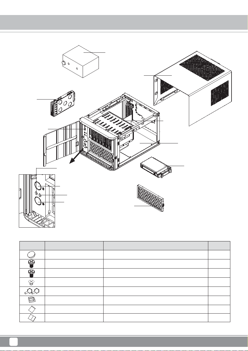
Disassemble Chart
2.5"HDD x 8
USB3.0 + SPK + MIC
SFX PSU(OPTION)
TOP COVE R
HDD CAGE
MINI-ITX(OPTION)
POWER LED
2.5"HDD x 1
POWER BUTTON
HDD LED
RESET BUTTON
PICTURE PURPOSEITEM QTY
RUBBER-E-FEET PAD
SCREW C 632*5
SCREW E M3*5
SCREW F M3*4
KEY
BUNCH WIRE TIES
ZIPPER BAG
Manual
FAN FILTER
For PSU
For Motherboard
Secure 2.5" SSD/HDD
32
4
4
8
2
1
1
1
2
Page 5

TOP
Case Storage Series CS280
Exterior Overview
FRONT
BACK
BOTTOM
RIGHT SIDELEFT SIDE
3
Page 6
Case Storage Series CS280
Installation Chart
Before you begin, please make sure that you
1
have all components collected
2
check that all components do not have compatibility problems with each other or with the case
3
if possible, assemble the components outside the case first to make sure they are working
keep the motherboard manual ready for reference during installation
4
prepare a Philips screwdriver.
5
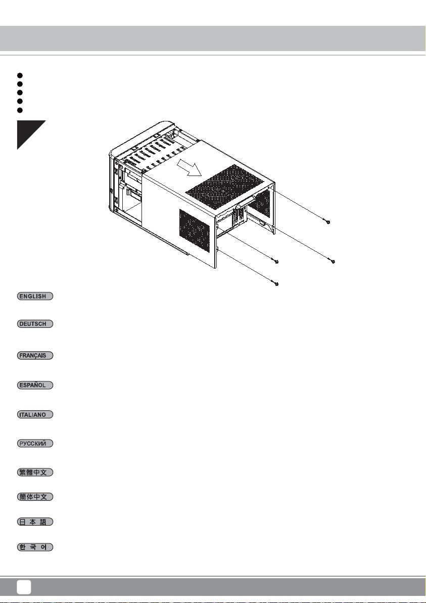
01
Remove screws from rear of the case then pull top cover backwards to remove it.
Entfernen Sie die Schrauben an der Gehäuserückseite und ziehen Sie dann die obere Abdeckung zum Entfernen nach hinten.
Retirez les vis à l'arrière du boîtier puis tirez le capot supérieur vers l'arrière pour le retirer.
Retire los tornillos de la parte trasera de la carcasa y luego tire de la cubierta superior hacia atrás para retirarla.
Rimuovere le viti dal retro del case, quindi spingere all'indietro il coperchio superiore per rimuoverlo.
Открутите винты на задней панели корпуса, затем потяните верхнюю крышку назад, чтобы снять её.
取下側板和機殼上方螺絲,依箭頭方向卸下機殼。
取下侧板和机箱上方螺丝,依箭头方向卸下机箱。
ケース後部からネジを外してから、上部カバーを後方に引いて取り外します。
케이스의 후면에서 나사를 제거한 후 상부 커버를 뒤로 당겨 제거합니다.
4
Page 7

Case Storage Series CS280
Installation Chart
02
Install memory, CPU cooler, and SATA cables onto the motherboard first. Then install the motherboard through the side of the case and connect
front I/O, fans, and power supply cables to it.
Installieren Sie zunächst Speicher, CPU-Kühler und SATA-Kabel am Motherboard. Installieren Sie dann das Motherboard durch die Gehäuseseite
und schließen Sie frontseitige Ein-/Ausgänge, Lüfter- und Netzteilkabel an.
Installez d'abord la mémoire, le dispositif de refroidissement du processeur et les câbles SATA sur la carte mère. Ensuite, installez la carte mère
par le côté du boîtier et raccordez-y les E/S de façade, les ventilateurs et les câbles d'alimentation.
Instale primero la memoria, el disipador de la CPU y los cables SATA en la placa base. Luego instale la placa base por el lateral de la carcasa
y conéctele los cables de E/S frontales, de los ventiladores y las fuentes de alimentación.
Per prima cosa, installare memoria, dispositivo di raffreddamento CPU e cavi SATA sulla scheda madre. Quindi installare la scheda madre attraverso
il lato del case e collegare I/O anteriore, ventole e cavi di alimentazione ad essa.
Сначала на системную плату установите чипы памяти, кулер процессора и подключите кабели SATA. Затем пропустите системную плату
через боковое отверстие в корпусе и подключите к ней кабели ввода/вывода на передней панели, кабели вентиляторов и блока питания.
將記憶體、CPU散熱器、SATA線,先安裝與連接至主機板,再將主機板由機殼側邊裝入,並連接IO線材、風扇線及電源線。
将内存、CPU散热器、SATA线,先安装与连接至主板,再将主板由机箱侧边装入,并连接IO线材、风扇线及电源线。
メモリ、CPUクーラー、およびSATAケーブルをマザーボードに取り付けます。それからケース側面からマザーボードを装着し、フロントI/O、ファ
ン、および電源ケーブルを接続します。
먼저 메인보드에 메모리, CPU 쿨러, SATA 케이블을 설치합니다. 그리고 케이스의 측면을 통해 메인보드를 설치하고 전면 I/O, 팬,전원 공급장치
케이블을 메인보드에 연결합니다.
5
Page 8

Case Storage Series CS280
Installation Chart
03
Install power supply as shown.
Installieren Sie das Netzteil wie abgebildet.
Installez l'alimentation comme indiqué.
Instale la fuente de alimentación como se muestra.
Installare l'alimentatore come mostrato.
Установите блок питания как показано.
將電源按圖示方向安裝。
将电源按图示方向安装。
図のように電源を装着します。
그림과 같이 전원 공급장치를 설치합니다.
6
Page 9

04
Please remove the screws holding the expansion card slot cover, and remove it.
Case Storage Series CS280
Installation Chart
Bitte entfernen Sie die Schrauben der Expansionssteckplatzabdeckungen und entfernen Sie sie.
Veuillez retirer les vis fixant les equerres des emplacements d’extension, puis retirez-les selon vos besoins.
Quite los tornillos que sujetan la cubierta del zocalo de la tarjeta de expansion y retirela.
Rimuovere le viti che che fissano la mascherina dello slot delle schede di espansione ed asportarlo.
Открутите шурупы на крышке слота карты расширения и снимите крышк.
請將鎖固擴充槽檔片的螺絲卸下,再將擴充槽檔片卸下。
请将锁固扩展槽档片的螺丝卸下,再将扩展槽档片卸下。
拡張カードカバーを固定しているネジを外し、カバーを取り外します。
확장슬롯 커버를 고정하고 있는 나사를 제거한 후 슬롯 커버를 제거합니다.
7
Page 10

Case Storage Series CS280
Installation Chart
05
Install your graphics card or expansion card.
Installieren Sie Ihre Grafik- oder andere Expansionskarte.
Installez vos cartes graphiques ou d’extensions.
Instale su tarjeta grafica o tarjeta de expansion.
Installare la scheda grafica o la scheda di espansione.
Установите графическую карту или карту расширения.
安裝您的顯示卡或擴充卡。
安装您的显示卡或扩充卡。
グラフィックスカードまたは拡張カードをインストールします。
그래픽카드나 확장 카드를 설치합니다.
8
Page 11

06
Reinstall the expansion card slot cover and secure with screws.
Case Storage Series CS280
Installation Chart
Installieren Sie die Expansionssteckplatzabdeckung wieder und befestigen Sie sie mit Schrauben.
Reinstallez la fixation des equerries et fixez-le avec des vis.
Reinstale la cubierta del zocalo de la tarjeta de expansion y fijela con tornillos.
Reinstallare la mascherina e serrarlo per mezzo delle viti.
Поместите на место крышку слота карты расширения и закрепите ее шурупами.
裝回擴充槽檔片並以螺絲固定。
装回扩展槽档片并以螺丝固定。
拡張カードスロットカバーを戻し、ネジで固定します。
확장슬롯 커버를 재설치한 후 나사로 고정시깁니다.
9
Page 12

Case Storage Series CS280
Installation Chart
07
Remove 2.5" drive trays, install drives onto them and reinstall back into the drive bracket.
Entfernen Sie die 2,5-Zoll-Laufwerksschächte, installieren Sie die Laufwerke in ihnen und bringen Sie sie wieder in der Laufwerkshalterung an.
Retirez les plateaux des lecteurs de 2,5", installez-y les lecteurs et réinstallez-les dans le support du lecteur.
Retire las bandejas de dispositivos de 2,5", instale en ellas los dispositivos y vuelva a reinstalarlas en el bracket para dispositivos.
Rimuovere i cassetti delle unità da 2,5", installare le unità sui cassetti, quindi reinstallare i cassetti sul supporto unità.
Извлеките лотки 2,5-дюймовых дисков, установите в них диски, затем установите лотки на место в кронштейн.
取出2.5吋硬碟抽取盒,安裝硬碟後再插入硬碟支架。
取出2.5吋硬盘抽取盒,安装硬盘后再插入硬盘支架。
2.5"ドライブトレイを取り外し、ドライブをトレイに装着してからドライブブラケットに戻します。
2.5"드라이브 트레이를 제거하고, 드라이브를 트레이 위에 설치한 후 드라이브 브래킷에 도로 설치합니다.
10
Page 13

Case Storage Series CS280
Installation Chart
08
Remove 2.5" drive trays, install drives onto them and reinstall back into the drive bracket, lockdown with key if needed and close the front door.
Entfernen Sie die 2,5-Zoll-Laufwerkseinsätze, installieren Sie Laufwerke in ihnen und installieren Sie sie wieder in der Laufwerkshalterung;
schließen Sie sie bei Bedarf mit dem Schlüssel ab und schließen Sie die Frontklappe.
Retirez le plateau de disque 2.5", installez le disque sur le plateau et remettez le plateau dans son emplacement, verrouillez avec la clé si besoin,
et refermez la porte avant
Retire las bandejas de dispositivo de 2,5", instale los dispositivos en ellas y vuelva a reinstalar el bracket de dispositivos, bloquee con la llave
si es necesario y cierre la puerta frontal.
Rimuovere i cassetti per dischi da 2,5", installare i dischi su di essi, quindi reinstallare nuovamente nell'unità, chiudere a chiave se necessario,
e chiudere lo sportello frontale.
Вытащите лотки для дисков, установите в них накопители и вставьте обратно в крепежные скобы. Если необходимо, заблокируйте диски
ключом и закройте переднюю дверцу.
取出內接2.5吋硬碟抽取盒,安裝硬碟後再插入硬碟支架,並用鎖匙鎖上及關上前方門板。
取出内接2.5吋硬盘抽取盒,安装硬盘后再插入硬盘支架,并用锁匙锁上及关上前方门板。
2.5"ドライブベイを取り外して、ドライブを装着してからドライブブラケットに戻します。必要であれば鍵でロックしてからフロントドアを
閉めます。
2.5" 드라이브 트레이를 제거하고, 드라이브를 트레이 위에 설치한 후 드라이브 브래킷 안에 도로 설치하고, 필요한 경우 키를 사용하여 잠근 후
전면 도어를 닫습니다.
11
Page 14

Case Storage Series CS280
Installation Chart
09
Connect all remaining cables and reinstall side panels to complete installation.
Verbinden Sie alle restlichen Kabel und bringen Sie zum Abschließen der Installation die Seitenblenden wieder an.
Raccordez tous les câbles restants et remontez les panneaux latéraux pour terminer l'installation.
Conecte todos los cables restantes y reinstale los paneles laterales para completar la instalación.
Collegare tutti i cavi rimanenti e reinstallare i pannelli laterali per completare l'installazione.
Подключите остальные кабели и установите на место боковые панели.
連接所有線材,裝回機殼側板,完成安裝。
连接所有线材,装回机箱侧板,完成安装。
残りのケーブルを全て接続し、サイドパネルを戻すとインストール完了です。
나머지 모든 케이블을 연결하고 측면 패널을 제자리에 다시 끼워 설치를 완료합니다.
12
Page 15

Case Storage Series CS280
Guide to hard drive backplane
1.Insert two 4pin peripheral connectors into the corresponding plugs on the backplane.
2.Connect the SAS/SATA ports on the backplane to corresponding SAS/SATA ports on the motherboard or expansion card with SAS/SATA cables.
※ To use SAS drive, you must have motherboard or expansion card with hardware SAS controller.
1. Verbinden Sie zwei vierpolige Peripherieverbinder mit den passenden Anschlüssen an der Rückwand.
2. Verbinden Sie die SAS/SATA-Ports an der Rückwand über die SAS/SATA-Kabel mit den entsprechenden SAS/SATA-Ports an Motherboard oder
Erweiterungskarte.
※ Zur Nutzung eines SAS-Laufwerks benötigen Sie ein Motherboard oder eine Erweiterungskarte mit Hardware-SAS-Controller.
1. Inserte dos conectores para periféricos de 4 pines en las clavijas correspondientes de la placa posterior.
2. Conecte los puertos SAS/SATA de la placa trasera a los puertos SAS/SATA correspondientes en la placa base o tarjeta de expansión con los
cables SAS/SATA.
※ Para usar un dispositivo SAS, debe tener una placa base o tarjeta de expansión con controlador SAS por hardware.
1. Inserte dos conectores para periféricos de 4 pines en las clavijas correspondientes de la placa posterior.
2. Conecte los puertos SAS/SATA de la placa trasera a los puertos SAS/SATA correspondientes en la placa base o tarjeta de expansión con
los cables SAS/SATA.
※ Para usar un dispositivo SAS, debe tener una placa base o tarjeta de expansión con controlador SAS por hardware.
1. Inserire due connettori periferiche a 4 pin nelle corrispondente spine sul backplane.
2. Collegare le porte SAS/SATA del backplane alle corrispondenti porte SAS/SATA della scheda madre o della scheda di espansione utilizzando cavi
SAS/SATA.
※ Per utilizzare unità SAS, è necessaria una scheda madre o scheda di espansione con controller hardware SAS.
1. Подсоедините два 4-контактных разъема для периферийных устройств к соответствующим гнездам на коммутационной панели.
2. Соедините разъемы SAS/SATA на соединительной панели с соответствующими разъемами SAS/SATA на системной плате или плате
расширения с помощью кабелей SAS/SATA.
※ Для использования диска SAS на системной плате или плате расширения должен быть установлен контроллер SAS.
1.請將兩個大4Pin電源接頭,插入背板電源輸入端。
2.將PCB板上SATA port 用SATA線接至對應之SATA孔。
※主機板或是擴充卡必須有SAS控制晶片方能支援使用SAS硬碟。
1.请将两个大4Pin电源接头,插入背板电源输入端。
2.将PCB板上SATA port 用SATA线接至对应之SATA孔。
※主板或是扩充卡必须有SAS控制芯片方能支持使用SAS硬盘。
1.2つの4ピン周辺装置コネクタをバッックプレートの対応する箇所に挿します。
2.バックプレーンのSAS/SATAポートをSAS/SATAケーブルで対応するSAS/SATAポートに接続します。
※SASドライブを使用するには、ハードウェアSASコントローラを備えたマザーボードまたは対応拡張カードが必要です。
1.두 개의 4핀 주변장치 커넥터를 뒷면의 해당 플러그에 삽입합니다.
2.SAS/SATA 케이블을 사용하여 백 플레인의 SAS/SATA 포트를 메인보드 또는 확장 카드의 해당 SAS/SATA 포트에 연결합니다.
※SAS 드라이브를 사용하려면, 하드웨어 SAS 컨트롤러가 탑재된 메인보드 또는 확장 카드가 있어야 합니다.
13
Page 16

Case Storage Series CS280
Connector Definition
(1) Front Panel Connectors
A.Power switch and reset switch installation guide:
Please refer to the motherboard manuals for the motherboard’s “Front Panel Connector” or “System Panel Connector” pin definitio
Power switch and reset switch have no polarity, so they can be connected in any orientation.
Bitte suchen Sie in der Motherboard-Dokumentation nach der Pinbelegung der Anschlüsse des Frontbedienfeldes („Front Panel Conne
oder „ System Panel Connectors“). Ein-/Austaste und Rücksetztaste benötigen keine bestimmte Polarität, können daher beliebig (o
und - zu achten) angeschlossen werden.
Veuillez-vous référer au manuel de votre carte mère pour la description des broches "des connecteurs du panneau frontal" et des
"des connecteurs du panneau système". Les interrupteurs d'allumage et de réinitialisation ne possède pas de polarité, donc ils peuvent être
branché dans les deux sens.
Por favor, consulte en los manuales de la placa base la configuración de pines del “Conector de panel frontal” ó “Conector de panel de sistema”
de su placa base. Los interruptores de encendido y reseteo no tienen polaridad, luego se pueden conectar con cualquier orientac
Fare riferimento al manuale della scheda madre nella sezione “Connettori del pannello frontale” o “Connettori del pannello di sistema”. Power
switch e reset switch non hanno polarità, posso essere pertanto connessi con qualsiasi orientamento.
Описание контактов разъемов приведены в разделах “Разъемы передней панели” или “Разъемы системной панели” руководства
пользователя материнской платы. Выключател ь питания и кнопка перезагрузки не имеют полярности, поэтому их можно подключать
в любой ориентации.
메인보드 매뉴얼의 전면패널 커넥터 혹은 시스템패널 커넥터 핀을 참조하기 바랍니다. 파워 스위치와 리셋 스위치는 극 성이 없어 어떤
방향으로 설치해도 무방합니다.
マザーボードの「フロントパネルコネクタ」または「システムパネルコネクタ」のピン配列についてはマザーボードマニュアルを参照してください。
電源スイッチとリセットスイッチに極性はないので、いずれの方向でも接続できま。
請參考主機說明書的Front Panel Connectors安裝Pin Define,將Connector插上;Power Switch 與Reset Switch並無正負極性之分,
反插正插都不影響功能性。
请参考主机说明书的Front Panel Connectors安装Pin Define,将Connector插上;Power Switch 与Reset Switch
反插正插都不影响功能性。
并无正负极性之分,
14
Page 17

Case Storage Series CS280
Connector Definition
B:LED indicators installation guide
Please refer to the motherboard manuals for the motherboard’s “Front Panel Connector ” or “System Panel Connector” pin definition.; the white/black
wires are negative while other colors are positive wires. The Power LED wires are separate pins for compatibility with different motherboard pin
definition so please make sure they are connected in the right polarity by referring to your motherboard manual.
Bitte suchen Sie in der Motherboard-Dokumentation nach der Pinbelegung der Anschlüsse des Frontbedienfeldes („Front Panel Connectors“ oder „
System Panel Connectors“). Die weißen/ schwarz Adern sind negativ (-), die farbigen Adern positiv (+).Die Kabel für die Betriebsanzeige-LED sind
zur Kompatibilität mit unterschiedlichsten Motherboards einzeln, nicht als kompletter Stecker ausgeführt. Achten Sie hier bitte auf die richtige
Polarität, lesen Sie in der Dokumentation Ihres Motherboards nach.
Veuillez-vous référer au manuel de votre carte mère pour la description des broches "des connecteurs du panneau frontal" et des broches "des connecteurs du panneau
système". Les câbles colorés en blanc/noir sont négatifs alors que ceux d'une autre couleur sont positifs. Les câbles de la LED Power sont séparés afin d'être compatible
avec différentes cartes mères, donc vérifiez bien qu'ils sont branchés avec la bonne polarité en vous référant au manuel de votre carte mère
Por favor, consulte en los manuales de la placa base la configuración de pines del “Conector de panel frontal” ó “Conector de panel de sistema” de
su placa base. Los cables de color blanco/negro son negativos mientras que los de color son positivos. Los cables LED de potencia tienen pines
separados para compatibilidad con diferentes definiciones de pines de la placa base luego por favor, asegúrese de que están conectados en la
polaridad correcta consultando el manual de su placa base.
Fare riferimento al manuale della scheda madre nella sezione “Connettori del pannello frontale” o “Connettori del pannello di sistema”. I cavi di
colore bianco/nero sono il polo negativo, mentre quelli di colore diverso il positivo.
Описание контактов разъемов приведены в разделах “Разъемы передней панели” или “Разъемы системной панели” руководства
пользователя материнской платы. Белые/черный провода - отрицательной полярности, цветные провода - положительной полярности.
Провода светодиодного индикатора питания имеют отдельные контакты для совместимости с различными типами контактов материнских
плат, поэтому обратитесь к руководству пользователя материнской платы и убедитесь, что полярность соблюдена.
메인보드 매뉴얼의 전면패널 커넥터 혹은 시스템패널 커넥터 핀을 참조하기 바랍니다. 하얀/검은선의 경우 음극이며, 다른 색의 경우
양극입니다. 파워 LED 선은 분리되어 다양한 메인보드에서 동작할 수 있도록 되어 있습니다. 그러므로 메인보드 매뉴얼을 참조하여 올바를
극성을 주의해 선택하시기 바랍니다.
マザーボードの「フロントパネルコネクタ」または「システムパネルコネクタ」ピン配列についてはマザーボードマニュアルを参照してください。
白/黑色のリード線はマイナスで、色の着いたリード線がプラスです。電源LEDリード線は種々のマザーボードピン定義と互換性を持たせるため分離されたピ
ンとなっているので、ご使用のマザーボードマニュアルを参照して、適切な極性に接続されるようお確かめください。
請參考主機說明書的Front Panel Connectors安裝Pin Define,將Connector插上;白/黑色線的部分為負極,彩色線的部分是正極。
Power LED為了適應各主機板的不同, 特別設計為散Pin樣式,請安心使用。
请参考说明书的Front Panel Connectors安装Pin Define,将Connector插上;白/黑色线的部份为负极,彩色线的部份为正极。
Power LED为了适应主机板的不同, 特别设计为散Pin样式,请安心使用。
15
Page 18

Case Storage Series CS280
Connector Definition
(2) Front I/O connector guide
Below are the front I/O connectors pin definition, please also check your motherboard manual to cross reference with motherboard’s
front I/O pin headers. SilverStone’s I/O connectors are in block type to simplify installation.
Nachstehend finden Sie die Pinbelegung der vorderen E/A-Anschlüsse; bitte gleichen Sie zudem das Handbuch Ihres Motherboards mit
den vorderen E/A-Pinzuweisungen ab. SilverStones E/A-Anschlüsse befinden sich zur Vereinfachung der Installation in Blockart.
Au dessous de la description des broches des ports d'E/S, veuillez aussi vérifier sur le manuel de votre carte mère de manière croisée
que les broches sont correctement placées. Les connecteurs d'E/S de SilverStone sont en bloc pour en simplifier leur installation.
A continuación tiene la definición de pines de los conectores frontales de E/S, también debe consultar el manual de su placa base para c
omprobar la referencia de los pines para E/S frontales. Los conectores de E/S de SilverStone son de bloque para simplificar la instalación.
Di seguito lo schema delle connessioni I/O frontali, confrontare lo schema con quanto riportato sul manuale della scheda madre per
effettuare una controllo incrociato. I connettori I/O Silverstone, per semplificare l’installazione, sono del tipo “a blocco”.
Ниже приведено описание контактов передних разъемов ввода/вывода. Обратитесь также к руководству пользователя материнской
платы за описанием передних разъемов ввода/вывода типа "пин-хедер". Разъемы ввода/вывода "SilverStone" - блочного типа, что
облегчает сборку.
아래는 전면 I/O 커넥터의 핀 설정이며, 메인보드 매뉴얼을 참조해 메인보드의 전면 I/O 핀 헤더와 맞추어 설치합니다.
Silverstone의 I/O 커낵터는 블록 타이브로 구성되어 설치를 간편화 했습니다.
以下はフロントI/Oコネクタピン配列ですが、お持ちのマザーボードのフロントI/Oピンヘッダは、マザーボードマニュアルをご参照ください。
シルバーストーンのI/Oコネクタは、インストールの容易なブロックタイプになっています。
下表為Front I/O Connectors的Pin Define,請參閱主機板說明書的各Front I/O Connectors Pin Define一一核對。
Front I/O Connectors完全採用集合Pin方式以簡化安裝。
下表为Front I/O Connectors的Pin Define,请参阅主机板说明书的各Front I/O Connectors Pin Define一一核对。
Front I/O Connectors完全采用集合Pin方式以简化安装。
USB 3.0 CONNECTOR
Pin 1
Vbus
IntA_P1_SSRX-
IntA_P1_SSRX+
GND
IntA_P1_SSTX-
IntA_P1_SSTX+
GND
IntA_P1_D-
IntA_P1_D+
ID
Pin 19
Vbus
IntA_P2_SSRXIntA_P2_SSRX+
GND
IntA_P2_SSTXIntA_P2_SSTX+
GND
IntA_P2_DIntA_P2_D+
Pin 11Pin 10
16
Page 19

Case Storage Series CS280
Component Size Limitations
Height limitation for CPU cooler is 65mm with 7mm clearance over the motherboard’s top edge.
Höhenbeschränkung für CPU-Kühler 65 mm mit einem Freiraum von 7 mm oberhalb der Motherboard-Oberkante.
La limitation de hauteur des refroidisseurs de processeurs est 65mm avec un espace de 7mm au-dessus du bord supérieur de la carte mere.
La limitación de altura para disipadores de CPU es de 65mm con un espacio libre de 7mm sobre el borde superior de la placa base.
La limitazione dell’altezza del dissipatore di calore CPU è di 65 millimetri con uno spazio libero di 7 mm sopra il bordo superiore della scheda madre.
Ограничение по высоте для системы охлаждения процессора составляет 65 мм с 7-мм зазором над верхним краем системной платы.
CPU 쿨러의 높이 제한은 65mm로서 메인보드 상단 가장자리 위로의 허용 오차가 7mm입니다.
CPUクーラーの高さ限度は、マザーボード上側の余裕7mmを取って、65mmです。
CPU散熱器限高是65mm,外緣允許超出主機板上邊界7mm。
CPU散热器限高是65mm,外缘允许超出主板上边界7mm。
17
Page 20

Case Storage Series CS280
Component Size Limitations
CS280 is compatible with SFX up to 100mm deep.
CS280 ist kompatibel mit SFX-Netzteilen mit einer Tiefe bis 100 mm.
Le CS280 est compatible avec les alimentations SFX jusqu'à 100 mm de profondeur.
La CS280 es compatible con FA SFX de hasta 100mm de profundidad.
CS280 è compatibile con SFX PSU con profondità fino a 100 mm.
Корпус CS280 совместим с блоками питания SFX глубиной до 100 мм.
CS280은 최대 깊이 100mm까지 SFX 또는와 호환됩니다.
CS280は、最大奥行き100mm までのSFX PSUに対応します。
CS280限定使用標準SFX電源,最長可安裝至100mm深的電源。
CS280限定使用标准SFX电源,最长可安装至100mm深的电源。
18
Page 21

Case Storage Series CS280
Component Size Limitations
CS280 support low profile expansion card up to 8.66 inch (220mm) long and the width support up to 60.75mm.
Das CS280 unterstützt Low-Profile-Erweiterungskarten mit einer Länge bis 8,66 Zoll (220 mm) und einer Breite bis 60.75 mm.
CS280 prend en charge les cartes d'extension low profile jusqu'à 8.66 pouces (220mm) de long et jusqu'à 60.75mm de haut.
El CS280 acepta una tarjeta de expansión de perfil bajo de hasta 8,66 pulgadas (220mm) y una anchura de hasta 60.75mm.
CS280 supporta schede di espansione a basso profilo fino a 8,66" (220 mm) di lunghezza e fino a 60.75 mm di larghezza.
CS280 поддерживает установку низкопрофильных плат расширения длиной до 8,66 дюймов (220 мм) и шириной до 60.75 мм.
CS280은 길이가 최대 220mm(8.66인치)이고 너비가 최대 60.75mm인 로우 프로필 확장 카드를 지원합니다.
CS280は最大長8.66インチ(220mm)、最大幅60.75mmのロープロファイル拡張カードに対応します。
CS280可支援8.66吋 (220mm)長/60.75mm寬Low profile介面卡。
CS280可支持8.66吋 (220mm)长/60.75mm宽Low profile界面卡。
19
Page 22

Case Storage Series CS280
Warranty Information
This product has a limited 1 year warranty in North America and Australia.
For information on warranty periods in other regions, please contact your reseller or SilverStone authorized distributor.
Warranty terms & conditions
1. Product component defects or damages resulted from defective production is covered under warranty.
Defects or damages with the following conditions will be fixed or replaced under SilverStone Technology’s jurisdiction.
a) Usage in accordance with instructions provided in this manual, with no misuse, overuse, or other inappropriate actions.
b) Damage not caused by natural disaster (thunder, fire, earthquake, flood, salt, wind, insect, animals, etc…)
c) Product is not disassembled, modified, or fixed. Components not disassembled or replaced.
d) Warranty mark/stickers are not removed or broken.
Loss or damages resulted from conditions other than ones listed above are not covered under warranty.
2. Under warranty, SilverStone Technology’s maximum liability is limited to the current market value for the product (depreciated value, excluding
shipping, handling, and other fees). SilverStone Technology is not responsible for other damages or loss associated with the use of product.
3. Under warranty, SilverStone Technology is obligated to repair or replace its defective products. Under no circumstances will SilverStone
Technology be liable for damages in connection with the sale, purchase, or use including but not limited to loss of data, loss of business, loss of
profits, loss of use of the product or incidental or consequential damage whether or not foreseeable and whether or not based on breach of warranty,
contract or negligence, even if SilverStone Technology has been advised of the possibility of such damages.
4. Warranty covers only the original purchaser through authorized SilverStone distributors and resellers and is not transferable to a second hand
purchaser.
5. You must provide sales receipt or invoice with clear indication of purchase date to determine warranty eligibility.
6. If a problem develops during the warranty period, please contact your retailer/reseller/SilverStone authorized distributors or SilverStone
http://www.silverstonetek.com.
Please note that: (i) You must provide proof of original purchase of the product by a dated itemized receipt; (ii) You shall bear the cost of shipping
(or otherwise transporting) the product to SilverStone authorized distributors. SilverStone authorized distributors will bear the cost of shipping
(or otherwise transporting) the product back to you after completing the warranty service; (iii) Before you send the product, you must be issued a
Return Merchandise Authorization (“RMA”) number from SilverStone. Updated warranty information will be posted on SilverStone’s official website.
Please visit http://www.silverstonetek.com for the latest updates.
Additional info & contacts
For North America (usasupport@silverstonetek.com)
SilverStone T echnology in North America may repair or replace defective product with refurbished product that is not new but has been
functionally tested.
Replacement product will be warranted for remainder of the warranty period or thirty days, whichever is longer. All products
should be sent back to the place of purchase if it is within 30 days of purchase, after 30 days, customers need to initiate RMA
procedure with SilverStone Technology in USA by first downloading the “USA RMA form for end-users” form from the below link
and follow its instructions.
http://silverstonetek.com/contactus.php
For Australia only (support@silverstonetek.com)
Our goods come with guarantees that cannot be excluded under the Australian Consumer Law.
You are entitled to a replacement or refund for a major failure and for compensation for any other reasonably foreseeable loss or
damage.
You are also entitled to have the goods repaired or replaced if the goods fail to be of acceptable quality and the failure does not
amount to a major failure.
Please refer to above “Warranty terms & conditions” for further warranty details.
SilverStone Technology Co., Ltd. 12F No. 168 Jiankang Rd., Zhonghe Dist.,
New Taipei City 235 Taiwan R.O.C. + 886-2-8228-1238
(standard international call charges apply)
For Europe (support.eu@silverstonetek.de)
For all other regions (support@silverstonetek.com)
20
Page 23

Page 24

NO:G11226800
 Loading...