

Page 1
Case Storage Series
Serie
s
Premium aluminum small form factor chassis
CS01
Page 2

Installation and system optimization guide:
The following manual and guides were carefully prepared by the SilverStone engineering team to
help you maximize the potential of your SilverStone product. Please keep this manual for future
reference when upgrading or performing maintenance on your system. A copy of this manual can also
be downloaded from our website at:
Product Overview
Special Features
Specification
Disassemble Chart
Exterior Overview
Installation Guide
Connector Definition
Componet Size Limitations
Optimal Thermal Performance Layout
Upgrade And Maintenance
Warranty Information
P.1
P.1
P.1
P.2
P.3
P.4
P.11
P.14
P.16
P.18
Page 3
Case Storage Series CS01
Product Overview
Introduction
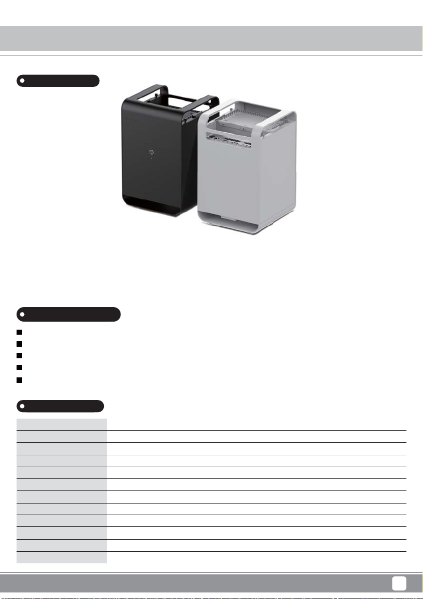
To meet increasing demand for cloud and local storage needs, SilverStone created the CS01 case to enable users to build sophisticated
and user-friendly system. Constructed with durable, sand-blasted anodized aluminium, the CS01 also utilizes SilverStone’s patented
90 degree rotated design to achieve efficient stack effect cooling for excellent thermal acoustic performance. Besides being durable
and practical, CS01 is also beautifully styled to fit perfectly in any office or home environment.
Special Features
Modern design with premium aluminum exterior
Compatible with Mini-ITX motherboard and SFX power supply
Vertical layout for stack effect cooling with built-in Air Penetrator fan
Accommodates two 3.5” and two 2.5” drives simultaneously
Supports low profile expansion card
Specification
Material
Model No.
Motherboard
Drive Bay
Cooling System
Expansion Slot
Front I/O Port
Power Supply
Expansion Card
Limitation of CPU cooler
Limitation of PSU
Dimension
Aluminum outer shell, steel body
SST-CS01S (Silver), SST-CS01B (Black)
Mini-ITX
Internal
Bottom
1x low profile
USB 3.0 x 2
SFX / SFX-L
1 x low profile up to 7.5”, width restriction – 2.95”
68mm
130mm (SFX-L)
210.5mm (W) x 322 mm (H) x 210 mm (D), 14.2 L
3.5" x 2 , 2.5” x 2
120mm AP fan x 1 , 1200rpm, 19.7dBA
1
Page 4
Case Storage Series CS01
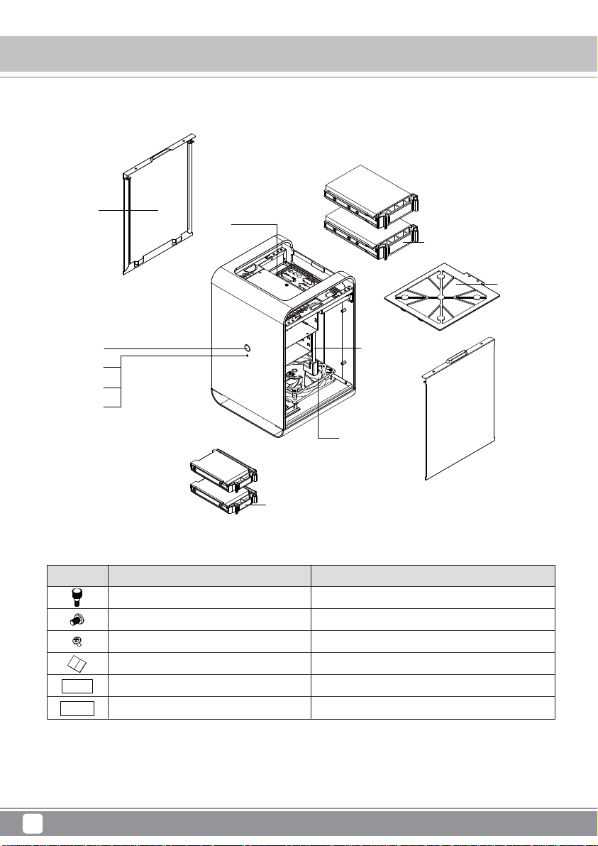
Disassemble Chart
Side Cover x 2
Power Button
Power LED
HDD LED
Reset Button
PICTURE PURPOSEITEM
THUMB - SCREW
632 - 5 - SCREW - NI
M3 - 4 SCREW - NI
Manual
STICKER
STICKER
USB3.0
3.5" HDD Tray x 2
Fan Filter x 1
Extended AC
power cord
12025 FAN x 1
2.5" HDD Tray x 2
Secure side panel
Secure motherboard, PSU, 3.5" HDD and water cooling pump
Secure 2.5" SSD/HDD
Description HDD content
Description HDD content
2
Page 5
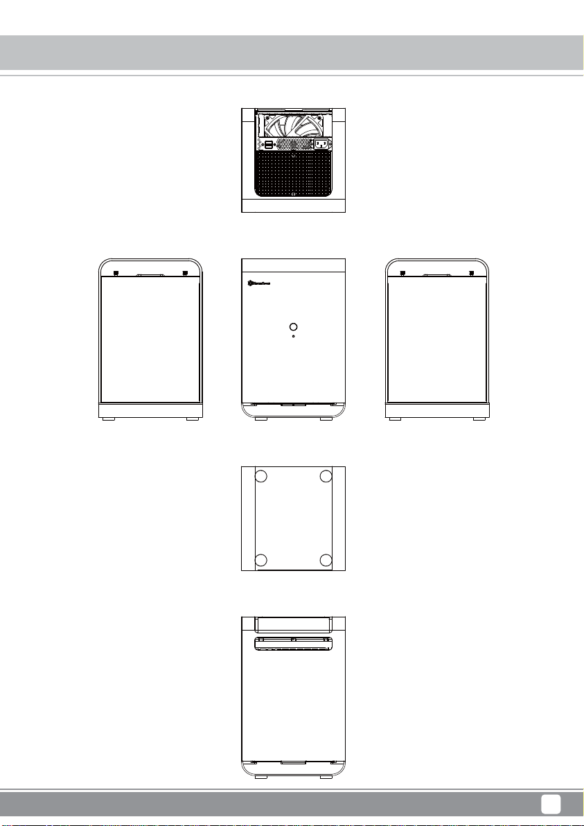
TOP
Case Storage Series CS01
Exterior Overview
FRONT
BOTTOM
BACK
RIGHT SIDELEFT SIDE
3
Page 6
Case Storage Series CS01
Installation Chart
Before you begin, please make sure that you
1
have all components collected
2
check that all components do not have compatibility problems with each other or with the case
3
if possible, assemble the components outside the case first to make sure they are working
keep the motherboard manual ready for reference during installation
4
prepare a Philips screwdriver.
5
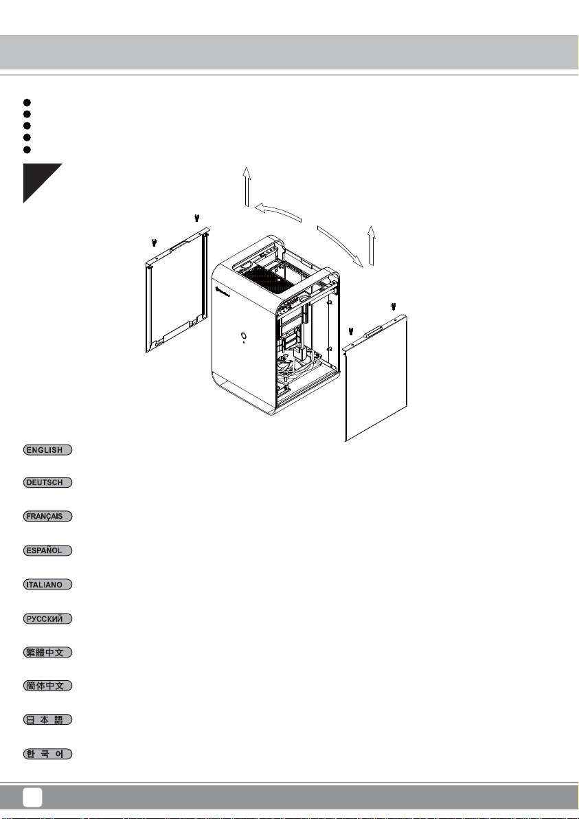
01
Unscrew two screws each from both side panels to remove them in the direction as shown.
Lösen Sie die beiden Schrauben an beiden Seitenblenden und entfernen Sie sie in der abgebildeten Ausrichtung.
Desserrez deux vis des deux panneaux latéraux pour les retirer dans le sens indiqué.
Quite dos tornillos de cada uno de los paneles laterales para retirarlos en la dirección que se muestra.
Svitare due viti da entrambi i pannelli laterali per rimuoverli nella direzione mostrata.
Чтобы снять боковые панели, отверните по два винта с каждой стороны панелей.
取下左右側板各兩顆螺絲,依箭頭方向卸下側板。
取下左右侧板各两颗螺丝,依箭头方向卸下侧板。
パネルの両サイドから各2本のネジを外し、図に示される方向に取り外します。
양 측면 패널에서 각각 2개의 나사를 풀어 그림과 같은 방향으로 이들을 분리합니다.
4
Page 7
Case Storage Series CS01
Installation Chart
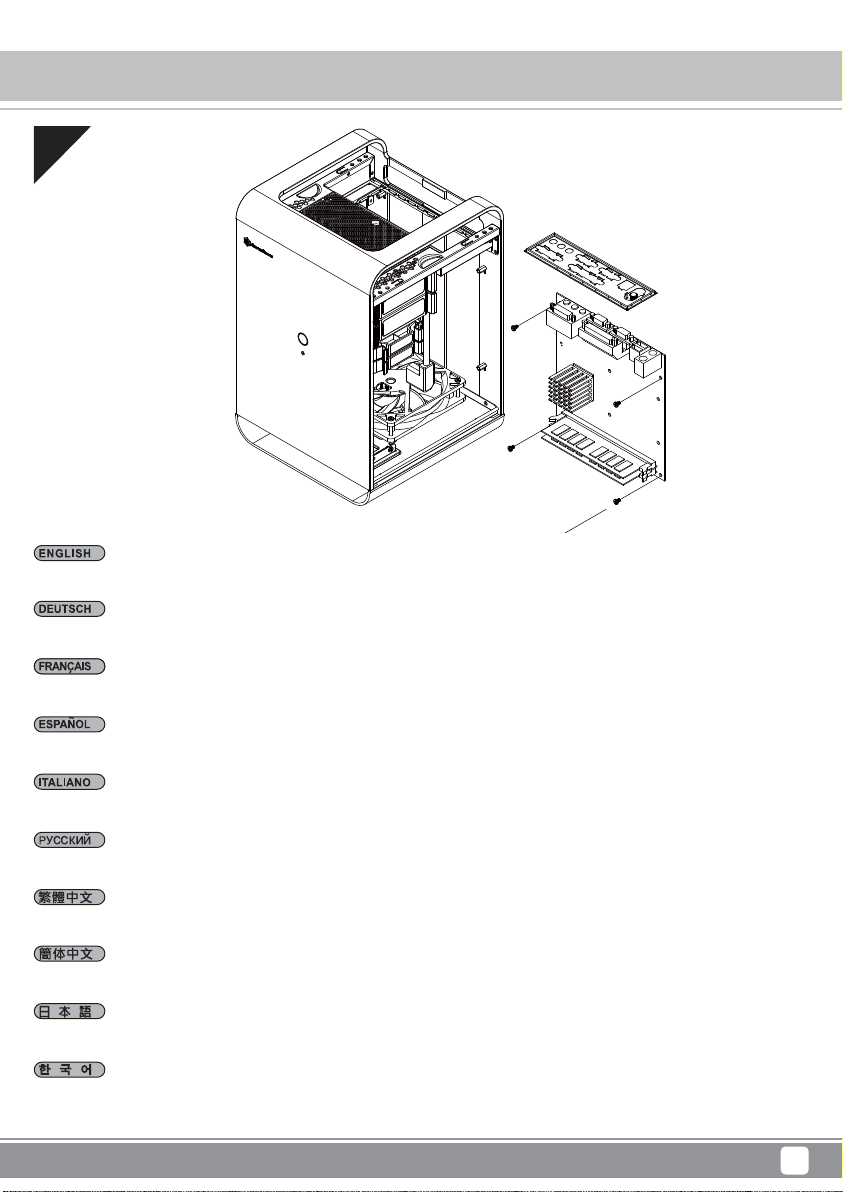
02
632-5-Screw x 4
Install memory, CPU cooler, and SATA cables onto the motherboard first. Then install the motherboard through the side of the case and connect
front I/O, fans, and power supply cables to it.
Installieren Sie zunächst Speicher, CPU-Kühler und SATA-Kabel am Motherboard. Installieren Sie dann das Motherboard durch die Gehäuseseite
und schließen Sie frontseitige Ein-/Ausgänge, Lüfter- und Netzteilkabel an.
Installez d'abord la mémoire, le dispositif de refroidissement du processeur et les câbles SATA sur la carte mère. Ensuite, installez la carte mère
par le côté du boîtier et raccordez-y les E/S de façade, les ventilateurs et les câbles d'alimentation.
Instale primero la memoria, el disipador de la CPU y los cables SATA en la placa base. Luego instale la placa base por el lateral de la carcasa
y conéctele los cables de E/S frontales, de los ventiladores y las fuentes de alimentación.
Per prima cosa, installare memoria, dispositivo di raffreddamento CPU e cavi SATA sulla scheda madre. Quindi installare la scheda madre attraverso
il lato del case e collegare I/O anteriore, ventole e cavi di alimentazione ad essa.
Сначала на системную плату установите чипы памяти, кулер процессора и подключите кабели SATA. Затем пропустите системную плату
через боковое отверстие в корпусе и подключите к ней кабели ввода/вывода на передней панели, кабели вентиляторов и блока питания.
將記憶體、CPU散熱器、SATA線,先安裝與連接至主機板,再將主機板由機殼側邊裝入,並連接IO線材、風扇線及電源線。
将内存、CPU散热器、SATA线,先安装与连接至主板,再将主板由机壳侧边装入,并连接IO线材、风扇线及电源线。
メモリ、CPUクーラー、およびSATAケーブルをマザーボードに取り付けます。それからケース側面からマザーボードを装着し、フロントI/O、ファ
ン、および電源ケーブルを接続します。
먼저 메인보드에 메모리, CPU 쿨러, SATA 케이블을 설치합니다. 그리고 케이스의 측면을 통해 메인보드를 설치하고 전면 I/O, 팬,전원 공급장치
케이블을 메인보드에 연결합니다.
5
Page 8
Case Storage Series CS01
Installation Chart
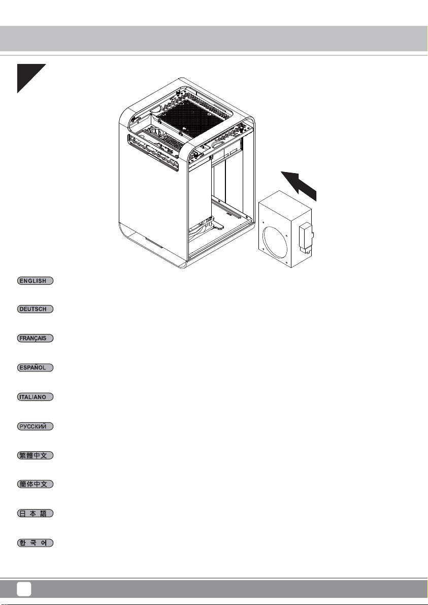
03
Install power supply in the direction as shown then connect to extension cable.
Installieren Sie das Netzteil in der abgebildeten Ausrichtung und schließen Sie es an das Verlängerungskabel an.
Installez l'alimentation dans le sens indiqué, puis raccordez-la au câble d'extension.
Instale la fuente de alimentación en la dirección que se muestra y luego conecte el cable de extensión.
Installare l’alimentatore nella direzione mostrata, quindi collegare alla prolunga.
Установите блок питания, как показано на рисунке, затем подключите кабельный удлинитель.
將電源按圖示方向安裝,並接上內接延長線。
将电源按图示方向安装,并接上内接延长线。
図に示される方向鬼電源を装着し、延長ケーブルを接続します。
전원 공급장치를 그림과 같은 방향으로 설치한 후 연장 케이블에 연결합니다.
6
Page 9

Case Storage Series CS01
Installation Chart
04
If low profile expansion card installation is required, remove expansion slot cover before proceeding.
Falls die Installation einer flachen Erweiterungskarte erforderlich ist, entfernen Sie die Erweiterungssteckplatzabdeckung, bevor Sie fortfahren.
Si une carte d'extension de faible encombrement doit être installée, retirez le cache de l'emplacement d'extension avant de continuer.
Si hace falta instalar una tarjeta de expansión de perfil bajo, retire la cobertura del zócalo de expansión antes de proceder.
Se è necessaria l'installazione della scheda di espansione a basso profilo, rimuovere il coperchio dell’alloggio di espansione prima di procedere.
Если требуется установить низкопрофильную плату расширения, снимите колпачок слота расширения.
若需安裝Low profile擴充卡,請先將檔板移除。
若需安装Low profile扩充卡,请先将档板移除。
ロープロファイル拡張カードの装着が必要な場合は、まず拡張スロットカバーを取り外します。
로우 프로필 확장 카드 설치가 필요한 경우, 계속하기 전에 확장 슬롯 커버를 제거하십시오.
7
Page 10

Case Storage Series CS01
Installation Chart
05
Install low profile expansion card.
Installieren Sie die flache Erweiterungskarte.
Installer une carte d'extension de faible encombrement.
Instale la tarjeta de expansión de perfil bajo.
Installare la scheda di espansione a basso profilo.
Установите низкопрофильную плату расширения.
安裝Low profile擴充卡。
安装Low profile扩充卡。
ロープロファイル拡張カードを装着します。
로우 프로필 확장 카드를 설치합니다.
8
Page 11

Case Storage Series CS01
Installation Chart
06
2.5" HDD Tray Label x 2
632-5-Screw x 4
3.5" HDD Tray Label x 2
M3-4-Screw x 4
Remove 2.5” and 3.5” drive trays, install drives onto them and reinstall back into the drive bracket.
Entfernen Sie die 2,5- und 3,5-Zoll-Laufwerksschächte, installieren Sie die Laufwerke in ihnen und bringen Sie sie wieder in der Laufwerkshalterung
an.
Retirez les plateaux des lecteurs de 2,5" et 3,5", installez-y les lecteurs et réinstallez-les dans le support du lecteur.
Retire las bandejas de dispositivos de 2,5” y 3,5”, instale en ellas los dispositivos y vuelva a reinstalarlas en el bracket para dispositivos.
Rimuovere i cassetti delle unità da 2,5” e 3,5”, installare le unità sui cassetti, quindi reinstallare i cassetti sul supporto unità.
Извлеките лотки 2,5-дюймовых и 3,5-дюймовых дисков, установите в них диски, затем установите лотки на место в кронштейн.
取出2.5吋/3.5吋硬碟抽取盒,安裝硬碟後再插入硬碟支架。
取出2.5吋/3.5吋硬盘抽取盒,安装硬盘后再插入硬盘支架。
2.5”および3.5”ドライブトレイを取り外し、ドライブをトレイに装着してからドライブブラケットに戻します。
2.5” 및 3.5” 드라이브 트레이를 제거하고, 드라이브를 트레이 위에 설치한 후 드라이브 브래킷에 도로 설치합니다.
9
Page 12

Case Storage Series CS01
Installation Chart
07
Connect all remaining cables and reinstall side panels to complete installation.
Verbinden Sie alle restlichen Kabel und bringen Sie zum Abschließen der Installation die Seitenblenden wieder an.
Raccordez tous les câbles restants et remontez les panneaux latéraux pour terminer l'installation.
Conecte todos los cables restantes y reinstale los paneles laterales para completar la instalación.
Collegare tutti i cavi rimanenti e reinstallare i pannelli laterali per completare l'installazione.
Подключите остальные кабели и установите на место боковые панели.
連接所有線材,裝回機殼側板,完成安裝。
连接所有线材,装回机壳侧板,完成安装。
残りのケーブルを全て接続し、サイドパネルを戻すとインストール完了です。
나머지 모든 케이블을 연결하고 측면 패널을 제자리에 다시 끼워 설치를 완료합니다.
10
Page 13

Case Storage Series CS01
Connector Definition
(1) Front Panel Connectors
A.Power switch and reset switch installation guide:
Please refer to the motherboard manuals for the motherboard’s “Front Panel Connector” or “System Panel Connector” pin definitio
Power switch and reset switch have no polarity, so they can be connected in any orientation.
Bitte suchen Sie in der Motherboard-Dokumentation nach der Pinbelegung der Anschlüsse des Frontbedienfeldes („Front Panel Conne
oder „ System Panel Connectors“). Ein-/Austaste und Rücksetztaste benötigen keine bestimmte Polarität, können daher beliebig (o
und - zu achten) angeschlossen werden.
Veuillez-vous référer au manuel de votre carte mère pour la description des broches "des connecteurs du panneau frontal" et des
"des connecteurs du panneau système". Les interrupteurs d'allumage et de réinitialisation ne possède pas de polarité, donc ils peuvent être
branché dans les deux sens.
Por favor, consulte en los manuales de la placa base la configuración de pines del “Conector de panel frontal” ó “Conector de panel de sistema”
de su placa base. Los interruptores de encendido y reseteo no tienen polaridad, luego se pueden conectar con cualquier orientac
Fare riferimento al manuale della scheda madre nella sezione “Connettori del pannello frontale” o “Connettori del pannello di sistema”. Power
switch e reset switch non hanno polarità, posso essere pertanto connessi con qualsiasi orientamento.
Описание контактов разъемов приведены в разделах “Разъемы передней панели” или “Разъемы системной панели” руководства
пользователя материнской платы. Выключател ь питания и кнопка перезагрузки не имеют полярности, поэтому их можно подключать
в любой ориентации.
메인보드 매뉴얼의 전면패널 커넥터 혹은 시스템패널 커넥터 핀을 참조하기 바랍니다. 파워 스위치와 리셋 스위치는 극 성이 없어 어떤
방향으로 설치해도 무방합니다.
マザーボードの「フロントパネルコネクタ」または「システムパネルコネクタ」のピン配列についてはマザーボードマニュアルを参照してください。
電源スイッチとリセットスイッチに極性はないので、いずれの方向でも接続できま。
請參考主機說明書的Front Panel Connectors安裝Pin Define,將Connector插上;Power Switch 與Reset Switch並無正負極性之分,
反插正插都不影響功能性。
请参考主机说明书的Front Panel Connectors安装Pin Define,将Connector插上;Power Switch 与Reset Switch
反插正插都不影响功能性。
并无正负极性之分,
11
Page 14

Case Storage Series CS01
Connector Definition
(1) Front Panel Connectors
B:LED indicators installation guide
Please refer to the motherboard manuals for the motherboard’s “Front Panel Connector ” or “System Panel Connector” pin definition.; the white/black
wires are negative while other colors are positive wires. The Power LED wires are separate pins for compatibility with different motherboard pin
definition so please make sure they are connected in the right polarity by referring to your motherboard manual.
Bitte suchen Sie in der Motherboard-Dokumentation nach der Pinbelegung der Anschlüsse des Frontbedienfeldes („Front Panel Connectors“ oder „
System Panel Connectors“). Die weißen/ schwarz Adern sind negativ (-), die farbigen Adern positiv (+).Die Kabel für die Betriebsanzeige-LED sind
zur Kompatibilität mit unterschiedlichsten Motherboards einzeln, nicht als kompletter Stecker ausgeführt. Achten Sie hier bitte auf die richtige
Polarität, lesen Sie in der Dokumentation Ihres Motherboards nach.
Veuillez-vous référer au manuel de votre carte mère pour la description des broches "des connecteurs du panneau frontal" et des broches "des connecteurs du panneau
système". Les câbles colorés en blanc/noir sont négatifs alors que ceux d'une autre couleur sont positifs. Les câbles de la LED Power sont séparés afin d'être compatible
avec différentes cartes mères, donc vérifiez bien qu'ils sont branchés avec la bonne polarité en vous référant au manuel de votre carte mère
Por favor, consulte en los manuales de la placa base la configuración de pines del “Conector de panel frontal” ó “Conector de panel de sistema” de
su placa base. Los cables de color blanco/negro son negativos mientras que los de color son positivos. Los cables LED de potencia tienen pines
separados para compatibilidad con diferentes definiciones de pines de la placa base luego por favor, asegúrese de que están conectados en la
polaridad correcta consultando el manual de su placa base.
Fare riferimento al manuale della scheda madre nella sezione “Connettori del pannello frontale” o “Connettori del pannello di sistema”. I cavi di
colore bianco/nero sono il polo negativo, mentre quelli di colore diverso il positivo.
Описание контактов разъемов приведены в разделах “Разъемы передней панели” или “Разъемы системной панели” руководства
пользователя материнской платы. Белые/черный провода - отрицательной полярности, цветные провода - положительной полярности.
Провода светодиодного индикатора питания имеют отдельные контакты для совместимости с различными типами контактов материнских
плат, поэтому обратитесь к руководству пользователя материнской платы и убедитесь, что полярность соблюдена.
메인보드 매뉴얼의 전면패널 커넥터 혹은 시스템패널 커넥터 핀을 참조하기 바랍니다. 하얀/검은선의 경우 음극이며, 다른 색의 경우
양극입니다. 파워 LED 선은 분리되어 다양한 메인보드에서 동작할 수 있도록 되어 있습니다. 그러므로 메인보드 매뉴얼을 참조하여 올바를
극성을 주의해 선택하시기 바랍니다.
マザーボードの「フロントパネルコネクタ」または「システムパネルコネクタ」ピン配列についてはマザーボードマニュアルを参照してください。
白/黑色のリード線はマイナスで、色の着いたリード線がプラスです。電源LEDリード線は種々のマザーボードピン定義と互換性を持たせるため分離されたピ
ンとなっているので、ご使用のマザーボードマニュアルを参照して、適切な極性に接続されるようお確かめください。
請參考主機說明書的Front Panel Connectors安裝Pin Define,將Connector插上;白/黑色線的部分為負極,彩色線的部分是正極。
Power LED為了適應各主機板的不同, 特別設計為散Pin樣式,請安心使用。
请参考说明书的Front Panel Connectors安装Pin Define,将Connector插上;白/黑色线的部份为负极,彩色线的部份为正极。
Power LED为了适应主机板的不同, 特别设计为散Pin样式,请安心使用。
12
Page 15

Case Storage Series CS01
Connector Definition
(2) Front I/O connector guide
Below are the front I/O connectors pin definition, please also check your motherboard manual to cross reference with motherboard’s
front I/O pin headers. SilverStone’s I/O connectors are in block type to simplify installation.
Nachstehend finden Sie die Pinbelegung der vorderen E/A-Anschlüsse; bitte gleichen Sie zudem das Handbuch Ihres Motherboards mit
den vorderen E/A-Pinzuweisungen ab. SilverStones E/A-Anschlüsse befinden sich zur Vereinfachung der Installation in Blockart.
Au dessous de la description des broches des ports d'E/S, veuillez aussi vérifier sur le manuel de votre carte mère de manière croisée
que les broches sont correctement placées. Les connecteurs d'E/S de SilverStone sont en bloc pour en simplifier leur installation.
A continuación tiene la definición de pines de los conectores frontales de E/S, también debe consultar el manual de su placa base para c
omprobar la referencia de los pines para E/S frontales. Los conectores de E/S de SilverStone son de bloque para simplificar la instalación.
Di seguito lo schema delle connessioni I/O frontali, confrontare lo schema con quanto riportato sul manuale della scheda madre per
effettuare una controllo incrociato. I connettori I/O Silverstone, per semplificare l’installazione, sono del tipo “a blocco”.
Ниже приведено описание контактов передних разъемов ввода/вывода. Обратитесь также к руководству пользователя материнской
платы за описанием передних разъемов ввода/вывода типа "пин-хедер". Разъемы ввода/вывода "SilverStone" - блочного типа, что
облегчает сборку.
아래는 전면 I/O 커넥터의 핀 설정이며, 메인보드 매뉴얼을 참조해 메인보드의 전면 I/O 핀 헤더와 맞추어 설치합니다.
Silverstone의 I/O 커낵터는 블록 타이브로 구성되어 설치를 간편화 했습니다.
以下はフロントI/Oコネクタピン配列ですが、お持ちのマザーボードのフロントI/Oピンヘッダは、マザーボードマニュアルをご参照ください。
シルバーストーンのI/Oコネクタは、インストールの容易なブロックタイプになっています。
下表為Front I/O Connectors的Pin Define,請參閱主機板說明書的各Front I/O Connectors Pin Define一一核對。
Front I/O Connectors完全採用集合Pin方式以簡化安裝。
下表为Front I/O Connectors的Pin Define,请参阅主机板说明书的各Front I/O Connectors Pin Define一一核对。
Front I/O Connectors完全采用集合Pin方式以简化安装。
USB 3.0 CONNECTOR
Pin 1
Vbus
IntA_P1_SSRX-
IntA_P1_SSRX+
GND
IntA_P1_SSTX-
IntA_P1_SSTX+
GND
IntA_P1_D-
IntA_P1_D+
ID
Pin 19
Vbus
IntA_P2_SSRXIntA_P2_SSRX+
GND
IntA_P2_SSTXIntA_P2_SSTX+
GND
IntA_P2_DIntA_P2_D+
Pin 11Pin 10
13
Page 16

Case Storage Series CS01
Component Size Limitations
The CS01 was designed to be as small as possible while maximizing interior space usage, please refer to the following guidelines forcomponent
selection and future upgrade considerations.
(1) CPU cooler height limitation
CPU cooler height limitation is 68mm.
Das CS01 unterstützt beim CPU-Kühler eine Maximalhöhe von 68 mm.
Le CS01 a une limitation de hauteur de 68mm pour le refroidisseur de CPU.
El CS01 tiene una limitación de altura de 68mm para un disipador de CPU.
CS01 ha una limitazione di 68 mm in altezza per il dispersore di calore CPU.
Корпус CS01 для установки вентилятора охлаждения процессора имеет ограничение по высоте 68 мм.
CPU 쿨러에 대한 CS01의 높이 제한은 68mm입니다.
CS01には、CPUクーラーに対して68mmの高さ制限があります。
Cooler限高為68mm。
Cooler限高为68mm。
(2) Power supply and optical drive limitation
CS01 is compatible with SFX or SFX-L PSU up to 130mm deep.
CS01 ist kompatibel mit SFX- und SFX-L-Netzteilen mit einer Tiefe bis 130 mm.
Le CS01 est compatible avec les alimentations SFX ou SFX-L jusqu'à 130 mm de profondeur.
La CS01 es compatible con FA SFX ó SFX-L de hasta 130mm de profundidad.
CS01 è compatibile con SFX o SFX-L PSU con profondità fino a 130 mm.
Корпус CS01 совместим с блоками питания SFX или SFX-L глубиной до 130 мм.
CS01은 최대 깊이 130mm까지 SFX 또는 SFX-L PSU와 호환됩니다.
CS01は、最大奥行き130mm までのSFXまたはSFX-L PSUに対応します。
CS01限定使用標準SFX電源,最長可安裝至130mm的SFX-L電源。
CS01限定使用标准SFX电源,最长可安装至130mm的SFX-L电源。
14
Page 17

Case Storage Series CS01
Component Size Limitations
(3) Expansion card length limitation
CS01 support low profile expansion card up to 7.5” long.
CS01 unterstützt flache Erweiterungskarten mit einer Länge bis 7,5 Zoll.
Le CS01 prend en charge une carte d'extension de faible encombrement jusqu'à 7,5" de long.
La CS01 acepta tarjetas de expansión de perfil bajo de hasta 7,5” de largo.
CS01 supporta schede di espansione a basso profilo lunghe fino a 7,5”.
Корпус CS01 поддерживает установку платы расширения длиной до 7,5 дюймов (19 см).
CS01은 최대 길이 7.5”까지 로우 프로필 확장 카드를 지원합니다.
CS01は、最大長7.5”までのロープロファイル拡張カードに対応します。
CS01 支援最長至7.5”長的Low profile擴充卡。
CS01 支持最长至7.5”长的Low profile扩充卡。
15
Page 18

Case Storage Series CS01
Optimal Thermal Performance Layout
CS01 has a unique 90 degree rotated motherboard design, below is a recommendation for component installation.
There are two main types of heat pipes used in popular aftermarket coolers, they are groove and powder. Groove heat pipes are very susceptible to
gravity while powder heat pipes are less so. To achieve best performance in either heat pipe technology, they need to be placed horizontally or have
the heat source side located below the other end of the heat pipe. We recommend choosing and installing components with heat pipes carefully by
taking into consideration of the following examples:
To achieve optimal performance in CS01, if you wish to upgrade CPU cooler, we recommend SilverStone’s AR05 or AR06. When installing
coolers with heat pipes, we recommend orientating them with heat pipes parallel to the surface or with heat source side below the other end of the
heat pipe with heatsink fins parallel to case airflow.
CPU-Kühlers
CS01 hat ein einzigartiges um 90 Grad drehbares Motherboard-Design; nachstehend finden Sie eine Empfehlung zur Komponenteninstallation.
Es gibt zwei Hauptarten von Wärmerohren, die bei den meisten Nachrüstkühlern verwendet werden: Nute und Pulver. Nuten-Wärmerohre sind sehr
empfindlich gegenüber der Gravitation, während Pulver-Wärmerohre weniger anfällig sind. Bei beiden Wärmerohrtechnologien gilt: Zur Erzielung
optimaler Leistung müssen diese horizontal platziert werden bzw. die Wärmequelle muss sich unterhalb des anderen Endes des Wärmerohrs befinden.
Beachten Sie bei der Auswahl und Installation von Komponenten mit Wärmerohren aufmerksam folgende Beispiele:
Zur Erzielung optimaler Leistung im CS01 empfehlen wir bei Aufrüstung des CPU-Kühlers SilverStones AR05 oder AR06. Bei einer Installation
von Kühlern mit Wärmerohren sollten Sie diese so ausrichten, dass die Wärmerohre parallel zur Oberfläche verlaufen bzw. sich die Wärmequelle
unterhalb des anderen Endes des Wärmerohrs mit den Kühlkörperlamellen parallel zum Gehäuseluftstrom befindet.
Refroidisseur CPU
Le CS01 dispose d'une conception unique de carte mère rotative à 90 degrés, vous trouverez ci-dessous des recommandations pour l'installation
des composants.
Deux types de caloducs sont utilisés dans la plupart des dispositifs de refroidissement, à rainures et à poudre. Les caloducs à rainures sont très
sensibles à la gravité alors que les caloducs à poudre le sont moins. Pour obtenir les meilleures performances avec les deux technologies de caloducs,
ils doivent être placés horizontalement ou avec le côté source de chaleur situé sous l'autre extrémité du caloduc. Nous recommandons de choisir
et d'installer soigneusement les composants avec des caloducs, en tenant compte des exemples suivants :
Pour obtenir des performances optimales avec le CS01, si vous souhaitez mettre à niveau le dispositif de refroidissement du processeur, nous vous
recommandons l'AR05 ou l'AR06 de SilverStone. En cas d'installation de dispositifs de refroidissement à caloducs, nous recommandons de les
orienter avec les caloducs parallèles à la surface ou avec le côté source de chaleur sous l'autre extrémité du caloduc, les ailettes du dissipateur
thermique parallèles au flux d'air du boîtier.
Refrigerador de CPU
La CS01 tiene un diseño de placa base único girado 90 grados, a continuación hay un recomendación para la instalación de componentes.
Hay dos tipos principales de tubos isotérmicos usados en disipadores del mercado postventa, son los de ranura y de polvo. Los tubos isotérmicos
de ranuras son muy susceptibles a la gravedad mientras los de polvo lo son menos. Para conseguir el mejor rendimiento con cualquier tecnología
de tubos isotérmicos, necesitan ser colocados de forma horizontal o tener la fuente de calor localizada en un lado bajo el otro extremo del tubo
isotérmico. Le recomendamos escoger e instalar componentes con cuidado con los tubos isotérmicos, teniendo en cuenta los siguientes ejemplos:
Para conseguir un rendimiento óptimo con la CS01, si desea mejorar el disipador de la CPU, le recomendamos instalar el AR05 ó AR06 de
SilverStone. Cuando instale disipadores con tubos isotérmicos, le recomendamos orientarlos con los tubos isotérmicos en paralelo con la superficie
o con el lado de la fuente de calor bajo el otro extremo del tubo isotérmico con las aletas del disipador paralelas al flujo de aire de la carcasa.
Raffreddamento della CPU
CS01 ha un design della scheda madre unico, ruotato di 90 gradi; di seguito sono indicate le raccomandazioni per l'installazione dei componenti.
Ci sono due tipi di heat pipe impiegati nei comuni accessori per dispersori di calore: “groove” e “powder”. Gli heat pipe “groove” sono molto
suscettibili alla gravità, mentre i “powder” lo sono di meno. Per ottenere le migliori prestazioni di entrambe le tecnologie, gli heat pipe devono essere
collocati orizzontalmente, oppure avere la sorgente di calore sotto o all’estremità del condotto. Si raccomanda di scegliere ed installare con
attenzione i componenti dotati di heat pipe tenendo in considerazione gli esempi che seguono.
Per ottenere le prestazioni ottimali di CS01, se si vuole aggiornare il dispositivo di raffreddamento CPU, si consiglia AR05 o AR06 SilverStone.
Durante l'installazione di dispositivi di raffreddamento con tubi termici, si raccomanda di orientare i tubi paralleli alla superficie, oppure con il lato
che origina il calore sotto l’altra estremità del tubo termico, con le alette del dissipatore parallele al flusso d'aria del case.
16
Page 19

Case Storage Series CS01
Optimal Thermal Performance Layout
Процессорного кулера
Корпус CS01 имеет уникальную конструкцию для установки системной платы с поворотом на 90 градусов, ниже приведены рекомендации
по установке компонентов системы.
В кулерах популярных марок применяются теплоотводные трубки двух основных типов: полые трубки и трубки с наполнителем. Полые
теплоотводные трубки подвержены воздействию силы тяжести гораздо сильнее, чем тепловые трубки с наполнителем
оптимального охлаждения при использовании теплоотводных трубок любого типа их следует располагать горизонтально или так, чтобы
источник тепла находился в нижней части трубок. Рекомендуется тщательно подбирать и устанавливать компоненты с теплоотводными
трубками, учитывая приведенные ниже примеры.
Если вы хотите заменить кулер процессора, для обеспечения оптимального режима работы в корпусе CS01 мы рекомендуем
использовать теплоотводы AR05 или AR06 компании SilverStone. При установке кулеров с теплоотводными трубками рекомендуется
устанавливать трубки параллельно поверхности или с источником тепла в нижней части трубок, располагая ребра теплоотводов
параллельно движению воздушного потока в корпусе.
CPU 쿨러
CS01 의 메인보드 디자인은 90도 회전식으로 독창적이며, 아래는 구성요소 설치를 위한 권장 예입니다.
인기있는 애프터마켓 쿨러에서 사용되는 히트 파이프에는 두 가지 종류, 즉 그루브 타입과 파우더 타입이 주를 이루고 있습니다. 그루브 히트
파이프는 중력에 매우 민감한 한편, 파우더 히트 파이프는 좀 덜한 편입니다. 어느 히트 파이프 기술에서든 최대 성능을 얻으려면, 수평으로
배치하거나 열원 쪽을 히트 파이프의 반대쪽 끝 아래에 배치해야 합니다. 다음 예를 고려하여 히트 파이프가 있는 구성품을 신중하게 선택하여
설치할 것을 권장합니다.
CS01 에서 최적의 성능을 얻기 위해 CPU 쿨러를 업그레이드하려는 경우, SilverStone의 AR05 또는 AR06을 사용할 것을 권장합니다. 히트
파이프와 함께 쿨러를 설치하는 경우, 히트 파이프가 표면과 평행을 이루거나 방열판 핀이 케이스 공기 흐름과 평행한 상태에서 열원 측면이 히트
파이프의 반대쪽 끝 아래에 놓이도록 하여 뱡향을 잡을 것을 권장합니다.
CPUクーラー
CS01 は、独特の90度回転マザーボード設計となっており、コンポーネントの装着は下記の方法が勧められています。
一般市場に出回るクーラーには、主に2種類のヒートパイプが使用されています。一つは溝付け、他方は粉体焼結です。溝付けヒートパイプは重
量に耐性を示し、対する粉体焼結パイプはさほど強度がありません。いずれのパイプ方式でもベストな性能を得るには、水平設置または熱発生源
をヒートパイプ他端の下方に置く必要があります。ヒートパイプ装備のコンポーネントの選択・設置には以下の例を考慮なさるようお勧めします。
CS01 での最適な性能を得るべくCPUクーラーのアップグレードを考慮される場合は、SilverStone製AR05またはAR06をお勧めします。ヒートパ
イプ装備のクーラーを装着する場合、表面に平行にパイプが設置、またはヒートパイプ他端より下方に熱発生源が来るようなもので、ヒートシン
クのフィンがエアフローに平行する向きであるものをお勧めします。
CPU Cooler
由於CS01 不同一般機殼,主機板為90度的安裝方向,請參考以下建議。
導熱管有兩種型式:溝槽與粉末導熱管,即使是比較高級的粉末導熱管也會受到地心引力的影響,多少會影響到效能;一般而言導熱管安裝呈水平方向或
是由下往上都沒有問題。但是由上往下散熱效能便會折損。因此我們建議在選配或安裝Cooler時需要先考慮方向性。
為了在CS01 有限的內部空間裡獲得最佳散熱,若您有改裝CPU散熱器,如我們推薦的銀欣AR05/AR06,建議您將散熱器方向為熱導管水平或朝上的
安裝方式,以順著CS01 的風流。
. Для достижения
CPU Cooler
由于CS01 不同一般机壳,主板为90度的安装方向,请参考以下建议。
导热管有两种型式:沟槽与粉末导热管,即使是比较高级的粉末导热管也会受到地心引力的影响,多少会影响到效能;一般而言导热管安装呈水平方向或
是由下往上都没有问题。但是由上往下散热效能便会折损。因此我们建议在选配或安装Cooler时需要先考虑方向性。
为了在CS01 有限的内部空间里获得最佳散热,若您有改装CPU散热器,如我们推荐的银欣AR05/AR06,建议您将散热器方向为热导管水平或朝上的
安装方式,以顺着CS01 的风流。
Horizontal style cooler
Good orientation Good orientation Bad orientation
17
Page 20

Case Storage Series CS01
Upgrade And Maintenance
CS01
’s positive air pressure design is an effective configuration that will reduce dust buildup inside the case. Small air particles or lint will
accumulate over time on intake filters instead of on the components inside the case. To maintain
to come, we recommend to clean all fan filters regularly every three months or half a year (depending on your environment). Below are steps to
remove fan filters.
CS01
’s excellent cooling performance for years
Das vorteilhafte Luftdruckdesign des
der Zeit sammeln sich kleine Partikel und Fusseln an den Luftzufuhrfiltern, anstatt an den Komponenten im Gehäuseinneren, an. Sie können eine
jahrelange optimale Kühlleistung des
Umgebungsbedingungen). Nachstehend finden Sie die Schritte zur Entfernung der Lüfterfilter.
La conception à pression d'air positive du
De petites particules d'air ou de peluche vont s'accumuler avec le temps sur les filtres d'aspiration, et non sur les composants à l'intérieur du boîtier.
Pour conserver les excellentes performances de refroidissement du
filtres des ventilateurs, tous les trois ou six mois (selon votre environnement). Vous trouverez ci-dessous les étapes vous expliquant comment retirer
les filtres des ventilateurs.
El diseño de presión de aire positiva de la
Pequeñas partículas de polvo ó pelusa se irán acumularán con el transcurso del tiempo en los filtros de entrada en lugar de en los componentes
del interior de la carcasa. Para mantener la excelente capacidad de refrigeración de la
con regularidad todos los filtros de los ventiladores cada tres meses ó seis meses (dependiendo de dónde viva). A continuación están los pasos
para quitar los filtros de los ventiladores.
Il design a pressione positiva di
infatti sui filtri invece che sui componenti interni. Per mantenere le eccellenti prestazioni di raffreddamento di
raccomandiamo di procedere ad una regolare pulizia dei filtri (con cadenza trimestrale o semestrale dipendentemente dall’ambiente un cui è
disposto il sistema). Di seguito i passi per la rimozione dei filtri.
Конструкция корпуса
препятствующую скоплению пыли внутри корпуса. Небольшие частицы и волокна, содержащиеся в воздухе, со временем будут
скапливаться на впускных фильтрах, а не на компонентах, находящихся внутри корпуса. Для поддержания превосходного охлаждения
компонентов в корпусе
раз в полгода (в зависимости от условий окружающей среды). Ниже приведена процедура для удаления фильтров вентиляторов.
CS01
的正壓差搭配濾網方式是經的起時間考驗最有效的防塵方式。在使用相當長一段時間後,棉屑灰塵或其他可能妨礙散熱效能的小異物只會卡在濾
網,而不是電腦內的元件上面。我們重視的散熱效能,是在您使用電腦長達2~3年後還能維持與全新的無異。為了維持這種散熱效能您只需要定期清理濾
網,而不是電腦裡面的元件。視環境而定,我們建議您每6個月~1年必須清理濾網,以下是濾網的拆卸步驟。
CS01
的正压差搭配滤网方式是经的起时间考验最有效的防尘方式。在使用相当长一段时间后,棉屑灰尘或其它可能妨碍散热效能的小异物只会卡在
滤网,而不是计算机内的组件上面。我们重视的散热效能,是在您使用计算机长达2~3年后还能维持与全新的无异。为了维持这种散热效能您只需要定
期清理滤网,而不是计算机里面的组件。视环境而定,我们建议您每6个月~1年必须清理滤网,以下是滤网的拆卸步骤。
CS01
CS01
CS01
ist eine effektive Konfiguration, die Staubablagerungen innerhalb des Gehäuses vermindert. Im Laufe
CS01
gewährleisten, indem Sie alle Lüfterfilter regelmäßig alle drei bis sechs Monate reinigen (je nach
CS01
est une configuration efficace permettant de réduire l'accumulation de la poussière dans le boîtier.
CS01
au fil des ans, nous vous recommandons de nettoyer l'ensemble des
CS01
es una configuración efectiva que reducirá la acumulación de polvo dentro de la carcasa.
CS01
en años venideros, le recomendamos que limpie
CS01
riduce considerevolmente gli accumuli di polvere all’interno del case. Le piccole particelle si accumulano
обеспечивает избыточное давление воздуха и, таким образом, имеет эффективную конфигурацию,
в течение многих лет рекомендуется регулярно очищать все фильтры вентиляторов: раз в 3 месяца или
CS01
negli anni a venire vi
CS01
の正圧設計は、ケース内のホコリの蓄積を減少させる有効な構造です。時と共に空気中の微粒子または糸くずはケース内のコンポーネト
上の代わりに取入れ口フィルタに溜まります。この先何年もの間SG10の素晴らしい冷却性能を維持するには、全てのファンを3ヶ月ないしは半年(
環境に依存) ごとに規則的に清掃するようお勧めします。以下は、ファンフィルタを取り外す手順です。
CS01
의 양압 디자인은 케이스 내부에 먼지가 싸이는 것을 방지 하기 위한 효과적인 디자인입니다. 작은 분진이나 먼지는 케이스 내부에 있는
필터에 시간에 따라 쌓이게 됩니다. SG10의 우수한 냉각 성능을 계속 유지하기 위헤서 매 3개월 혹은 6개월(사용환경에 따라)마다 필터 청소를
권장합니다. 다음의 필터 제거 과정을 참고하세요.
18
Page 21

Case Storage Series CS01
Upgrade And Maintenance
Fan filter is located on the bottom of the case, press down on it to remove from the case.
If you accidentally loose/damage filters or need additional ones for backup, please contact your local SilverStone retailers or distributors for purchasing
information:
http://www.silverstonetek.com/wheretobuy_all.php
Ein Lüfterfilter befindet sich an der Unterseite des Gehäuses; entfernen Sie ihn durch Drücken vom Gehäuse.
Wenn Sie einen Lüfterfilter als Zusatz, zum Austausch bei Verlust oder Beschädigung oder einfach als Reserve erwerben möchten, suchen Sie
einfach auf unseren Internetseiten nach einem Händler oder Distributor in Ihrer Nähe:
http://www.silverstonetek.com/wheretobuy_all.php
Le filtre du ventilateur se situe au fond du boîtier, appuyez dessus pour le retirer du boîtier.
Pour acheter un filtre du ventilateur au détail comme pour l’améliorer ou pour le remplacer en caisson de perte, de dommage ou simplement en
rechange, vous pouvez rechercher sur notre site Internet pour connaître les revendeurs ou les distributeurs les plus proches de chez vous:
http://www.silverstonetek.com/wheretobuy_all.php
El filtro del ventilador está situado en la parte inferior de la carcasa, presiónelo hacia abajo para sacarlo de la carcasa.
Para comprar un filtro para ventilador como mejora o reemplazo en caso de pérdida, daño o simplemente como recambio, puede buscar en nuestra
página web para encontrar el distribuidor o vendedor autorizado más cercano:
http://www.silverstonetek.com/wheretobuy_all.php
Il filtro della ventola si trova nella parte inferiore del case, premerlo per rimuoverlo dal case.
Per acquistare un filtro della ventola al dettaglio per la sostituzione in caso di perdita, danni o semplicemente uno di riserva, è possibile cercare sul
nostro sito web i rivenditori o distributori più vicini:
http://www.silverstonetek.com/wheretobuy_all.php
Фильтр вентилятора расположен в нижней части корпуса, для его извлечения нажмите на него.
На нашем сайте Вы найдете ближайшего торгового посредника или дистрибьютора, у которого можно приобрести фильтр вентилятора для
замены в случае потери или повреждения старого фильтра, или про запас.
http://www.silverstonetek.com/wheretobuy_all.php
風扇濾網位於機殼底部,向下按壓即可抽出。
添購濾網:
如果您不慎遺失、人為損壞或只是想要多購買濾網備用。請與我們的經銷點聯絡進行購買。
請上SilverStone網站查詢各區域經銷 http://www.silverstonetek.com.tw/wheretobuy_all.php?area=tw
风扇滤网位于机壳底部,向下按压即可抽出。
添购滤网:
如果您不慎遗失、人为损坏或只是想要多购买滤网备用。请与我们的经销点联络进行购买。
请上SilverStone网站查询各区域经销 http://www.silverstonetek.com/wheretobuy.php?wname=china&area=cn&pid=
ファンフィルターはケース底部に位置します。下方に押すとケースから取り外せます。.
アップグレードまたは損失の場合の交換用、または単にバックアップとして小売ファン・フィルタを購入するには、最寄りの小売業者または卸売
業者を下記の当社ウェブサイトから検索できます。
http://www.silverstonetek.com/wheretobuy_all.php
팬 필터는 케이스 하단에 위치하는데, 이를 아래로 눌러 케이스에서 분리합니다.
팬 필터가 분실 또는 손상되어 소매로 팬 필터를 구입하거나 단순히 여분으로 구입하려는 경우, 당사의 웹사이트에서 가까운 판매점을
검색할 수 있습니다.
http://www.silverstonetek.com/wheretobuy_all.php
19
Page 22

Case Storage Series CS01
Warranty Information
This product has a limited 1 year warranty in North America and Australia.
For information on warranty periods in other regions, please contact your reseller or SilverStone authorized distributor.
Warranty terms & conditions
1. Product component defects or damages resulted from defective production is covered under warranty.
Defects or damages with the following conditions will be fixed or replaced under SilverStone Technology’s jurisdiction.
a) Usage in accordance with instructions provided in this manual, with no misuse, overuse, or other inappropriate actions.
b) Damage not caused by natural disaster (thunder, fire, earthquake, flood, salt, wind, insect, animals, etc…)
c) Product is not disassembled, modified, or fixed. Components not disassembled or replaced.
d) Warranty mark/stickers are not removed or broken.
Loss or damages resulted from conditions other than ones listed above are not covered under warranty.
2. Under warranty, SilverStone Technology’s maximum liability is limited to the current market value for the product (depreciated value, excluding
shipping, handling, and other fees). SilverStone Technology is not responsible for other damages or loss associated with the use of product.
3. Under warranty, SilverStone Technology is obligated to repair or replace its defective products. Under no circumstances will SilverStone
Technology be liable for damages in connection with the sale, purchase, or use including but not limited to loss of data, loss of business, loss of
profits, loss of use of the product or incidental or consequential damage whether or not foreseeable and whether or not based on breach of warranty,
contract or negligence, even if SilverStone Technology has been advised of the possibility of such damages.
4. Warranty covers only the original purchaser through authorized SilverStone distributors and resellers and is not transferable to a second hand
purchaser.
5. You must provide sales receipt or invoice with clear indication of purchase date to determine warranty eligibility.
6. If a problem develops during the warranty period, please contact your retailer/reseller/SilverStone authorized distributors or SilverStone
http://www.silverstonetek.com.
Please note that: (i) You must provide proof of original purchase of the product by a dated itemized receipt; (ii) You shall bear the cost of shipping
(or otherwise transporting) the product to SilverStone authorized distributors. SilverStone authorized distributors will bear the cost of shipping
(or otherwise transporting) the product back to you after completing the warranty service; (iii) Before you send the product, you must be issued a
Return Merchandise Authorization (“RMA”) number from SilverStone. Updated warranty information will be posted on SilverStone’s official website.
Please visit http://www.silverstonetek.com for the latest updates.
Additional info & contacts
For North America (usasupport@silverstonetek.com)
SilverStone T echnology in North America may repair or replace defective product with refurbished product that is not new but has been functionally tested.
Replacement product will be warranted for remainder of the warranty period or thirty days, whichever is longer. All products should be sent
back to the place of purchase if it is within 30 days of purchase, after 30 days, customers need to initiate RMA procedure with SilverStone Technology
in USA by first downloading the “USA RMA form for end-users” form from the below link and follow its instructions.
http://silverstonetek.com/contactus.php
For Australia only (support@silverstonetek.com)
Our goods come with guarantees that cannot be excluded under the Australian Consumer Law.
You are entitled to a replacement or refund for a major failure and for compensation for any other reasonably foreseeable loss or damage.
You are also entitled to have the goods repaired or replaced if the goods fail to be of acceptable quality and the failure does not amount to a major failure.
Please refer to above “Warranty terms & conditions” for further warranty details.
SilverStone Technology Co., Ltd. 12F No. 168 Jiankang Rd., Zhonghe Dist., New Taipei City 235 Taiwan R.O.C. + 886-2-8228-1238
(standard international call charges apply)
For Europe (support.eu@silverstonetek.de)
For all other regions (support@silverstonetek.com)
20
Page 23

Page 24

G11223240
 Loading...