

Page 1
Page 2
Installation and system optimization guide:
The following manual and guides were carefully prepared by the SilverStone engineering team to
help you maximize the potential of your SilverStone product. Please keep this manual for future
reference when upgrading or performing maintenance on your system. A copy of this manual can also
be downloaded from our website at:
Product Overview
Special Features
Specification
Disassemble Chart
Exterior Overview
Installation Guide
Connector Definition
Componet Size Limitations
Upgrade And Maintenance
Q&A
P.1
P.1
P.1
P.2
P.3
P.4
P.20
P.23
P.27
P.30
Warranty Information
Page 3
SUGO Series SG13
r
dut O
v
S
on
i-I
TX
into mainstream DIY (do it yourself) market in 2009 with the Sugo SG05, SilverStone is look
h S
G13
, a
ne
wly
Product Overview
Introduction
SG13B
SG13B
-Q
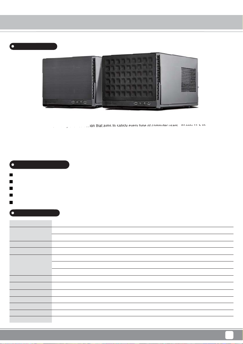
After bringing Mini-ITX into mainstream DIY (do it yourself) market in 2009 with the Sugo SG05, SilverStone is looking to define the
category again with SG13, a newly evolved design that aims to satisfy every type of computer users. At only 11.5 liters in size, it has
suitably small statue for easily integrating into numerous computing environments and will comfortably fit many standard components
for general purpose or office builds. For enthusiasts and in keeping with Sugo series’ famed tradition, the SG13’s ability to fit 10.5” long
expansion card, standard ATX power supply, and all-in-one liquid cooler in 120mm or 140mm size will help produce amazingly small
and powerful systems.
Special Features
Support standard-length expansion cards (10.5 inches)
Mini-DTX / Mini-ITX motherboard & ATX PSU compatible
Support 120mm or 140mm single fan All-in-One Liquid Cooler
Support 2.5” and 3.5” hard drives
Elevated standoff for motherboard back side components
Specification
Material
Model No.
Motherboard
Drive Bay
Cooling System
Expansion Slot
Front I/O Port
Power Supply
Expansion Card
Limitation of CPU cooler
Limitation of PSU
Dimension
* Maximum length for PSU is 150mm, we recommend 140mm due to varying connector locations on PSUs and the unique structure of SG13.
Mesh or plastic front panel, steel body
SST-SG13B (black, mesh front panel)
SST-SG13B-Q (black, plastic front panel with faux aluminum finish)
Mini-DTX, Mini-ITX
Internal
Front
Sides
Top
2
USB 3.0 x 2, Audio x 1, MIC x 1
Optional standard PS2 (ATX)
Compatible up to 10.5” long, width restriction-5.11"
61mm
150mm*
222mm (W) x 181 mm (H) x 285 mm (D) 11.5 liters
3.5” x 1 or 2.5” x 2 + 2.5” x 1
1 x 120mm/140mm fan slot compatible with radiator (option)
Oversized vents
Oversized vents
1
Page 4
SUGO Series SG13
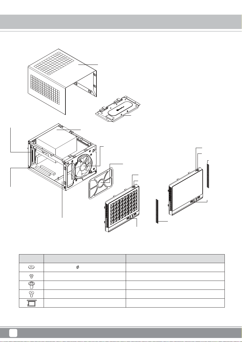
Disassemble Chart
EXPANSION SLOTS * 2
ATX / PS2 PSU (OPTION)
TOP COVER
3.5” DRIVE BAY * 1 OR 2.5” DRIVE BAY * 2
MOTHERBOARD
(Mini-DTX, Mini-ITX) (OPTION)
PICTURE PURPOSEITEM
FAN - RUBBER - 10 - G6
SCREW - I - 6 - 32 * 5-BK
SCREW - P / W - M3 * 6 - BK
SCREW - FT - M3 * 4 - BK
BUNCH WIRE SET
2.5” DRIVE BAY * 1
12025 FAN * 1 OR 14025 FAN (OPTION)
FAN FILTER (SG13B ONLY)
RESET BUTTON
POWER BUTTON
(SG13B)
USB 3.0 * 2 +
SPK + MIC
Fan rubber pads for noise dampening
Secure PSU, 3.5" HDD
Secure motherboard
Secure 2.5" SSD/HDD
For cable management
(SG13B-Q)
PVC - FILTER
RESET BUTTON
POWER BUTTON
PVC - FILTER
USB 3.0 * 2 +
SPK + MIC
2
Page 5
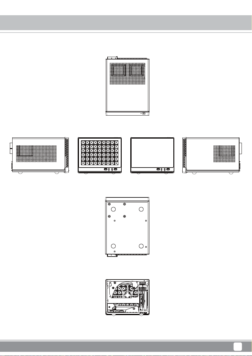
TOP
SUGO Series SG13
Exterior Overview
FRONT
SG13B SG13B-Q
BOTTOM
BACK
FRONT
RIGHT SIDELEFT SIDE
3
Page 6
SUGO Series SG13
Installation Chart
Before you begin, please make sure that you
1
have all components collected
2
check that all components do not have compatibility problems with each other or with the case
3
if possible, assemble the components outside the case first to make sure they are working
keep the motherboard manual ready for reference during installation
4
prepare a Philips screwdriver.
5
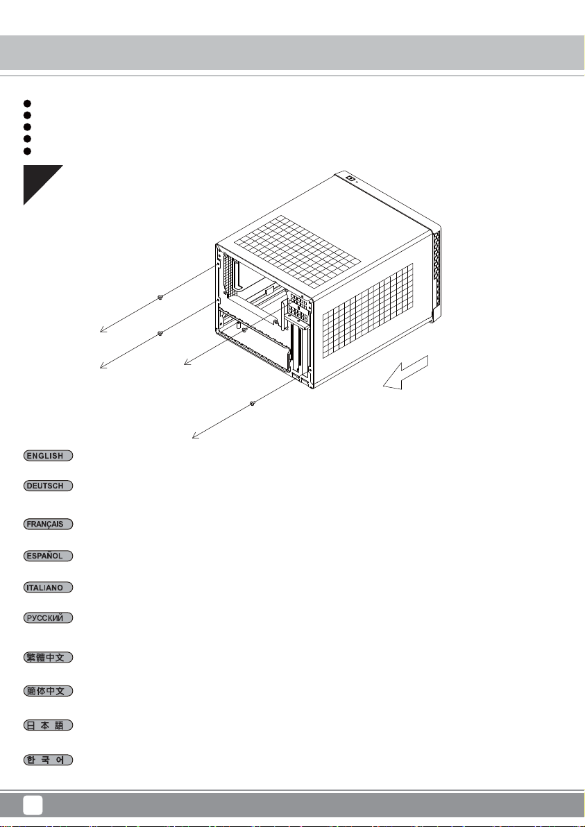
01
Please remove the screws holding the top cover with a screw driver, and then pull it toward the back and lift it outward away from chassis.
Bitte entfernen Sie die Schrauben, die die obere Abdeckung halten, mit einem Schraubendreher; ziehen Sie die Abdeckung dann nach hinten und
nehmen Sie sie nach außen vom Gehäuse ab.
Veuillez retirer les vis qui retiennent le couvercle supérieur avec un tournevis, puis le tirer vers l'arrière et le soulever vers l'extérieur du châssis.
Por favor, quite los tornillos que sujetan la cubierta superior con un destornillador y luego tire hacia atrás y levántela apartándola del chasis.
Utilizzando un cacciavite, rimuovere le viti che fissano il coperchio superiore, quindi tirarlo indietro e sollevarlo allontanandolo dal telaio.
С помощью отвертки удалите винты, крепящие верхнюю крышку, а затем потяните ее назад и, подняв в направлении наружу, снимите с
корпуса.
請以螺絲起子卸下鎖固上蓋的螺絲,向後拉後再自機箱向上取出。
请以螺丝起子卸下锁固上盖的螺丝,向后拉后再自机箱向上取出。
上面カバーを固定しているネジをドライバーで外し、後方に引き上げてケースから取り外します。
스크루드라이버를 사용하여 상부 커버를 고정하는 나사를 푼 후 커버를 뒤쪽으로 당기고 바깥쪽으로 들어올려 섀시에서 분리합니다.
4
Page 7
SUGO Series SG13
Installation Chart
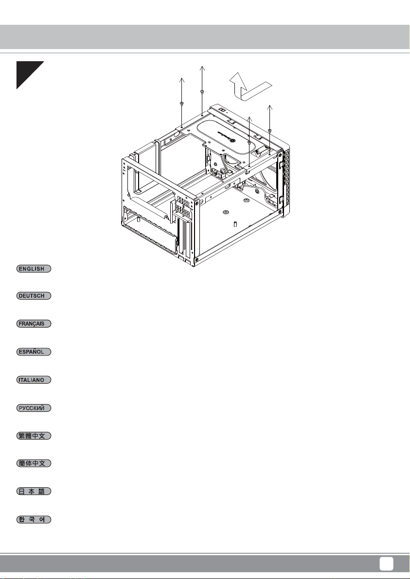
02
Remove the screws holding the hard drive bracket with a screw driver as shown, then remove the cage outward from the chassis.
Entfernen Sie die Schrauben, die die Festplattenhalterung halten, wie abgebildet mit einem Schraubendreher; nehmen Sie dann den Käfig aus dem
Gehäuse.
Retirez les vis de fixation du support de disque dur à l'aide d'un tournevis, comme indiqué, puis retirez la cage vers l'extérieur du châssis.
Quite los tornillos que sujetan el bracket para discos duros con un destornillador tal y como se muestra, luego saque la carcasa del chasis.
Rimuovere le viti che fissano il supporto del disco rigido utilizzando un cacciavite come mostrato, quindi estrarre la gabbia dal telaio.
С помощью отвертки отверните винты крепления кронштейна жесткого диска, затем извлеките отсек из корпуса.
請依圖示先以螺絲起子將鎖固硬碟架的螺絲卸下,再將硬碟架自機殼中取出。
请依图标先以螺丝起子将锁固硬盘架的螺丝卸下,再将硬盘架自机壳中取出。
図のようにドライバーでハードディスクブラケットを固定しているネジを取り外してから、ケースからケージを取り出します。
그림과 같이 스크루드라이버를 사용하여 하드 드라이브 브래킷을 고정하는 나사를 푼 후, 케이지를 섀시로부터 분리하여 꺼냅니다.
5
Page 8
SUGO Series SG13
Installation Chart
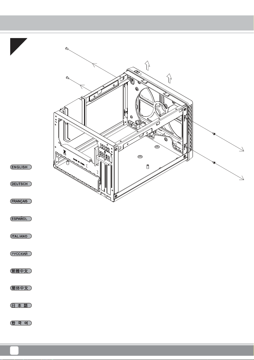
03
Remove front panel.
Entfernen Sie die Frontblende.
Enlevez le panneau frontal.
Retire el panel frontal.
Rimuovere il pannello frontale.
Снимите лицевую панель.
拆卸前面板。
拆卸前面板。
フロントパネルを取り外します。
전면 패널을 분리합니다.
6
Page 9
04
Install motherboard into the chassis.
SUGO Series SG13
Installation Chart
Installieren Sie das Motherboard im Gehäuse.
Installez la carte mère sur le châssis.
Instale la placa base en el chasis.
Installare la scheda madre nel telaio.
Установите системную плату в корпус.
將主機板安裝上機殼。
将主板安装上机壳。
ケースにマザーボードを装着します。
메인보드를 섀시에 설치합니다.
7
Page 10
SUGO Series SG13
Installation Chart
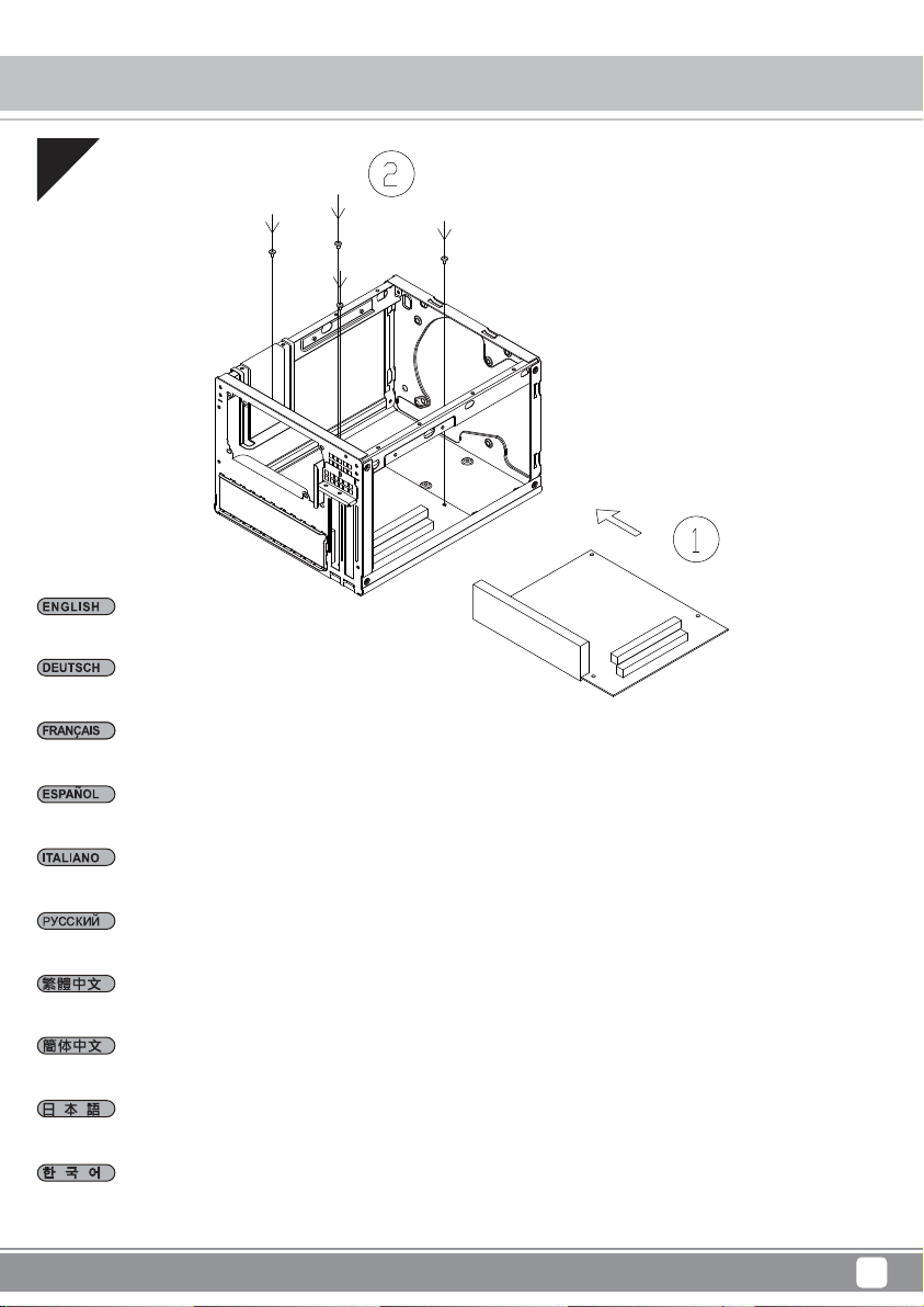
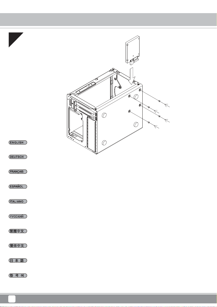
05
Install 2.5” drive onto the bottom panel.
Installieren Sie das 2,5-Zoll-Laufwerk an der Bodenplatte.
Installez le lecteur 2,5" sur le panneau inférieur.
Instale el dispositivo de 2,5” en el panel inferior.
Installare l’unità da 2,5” sul pannello inferiore.
Установите 2,5-дюймовый привод на нижнюю панель.
安裝底板的2.5吋硬碟。
安装底板的2.5吋硬盘。
2.5"ドライブを底部パネル上にインストールします。
2.5” 드라이브를 하단 패널에 설치합니다.
8
Page 11
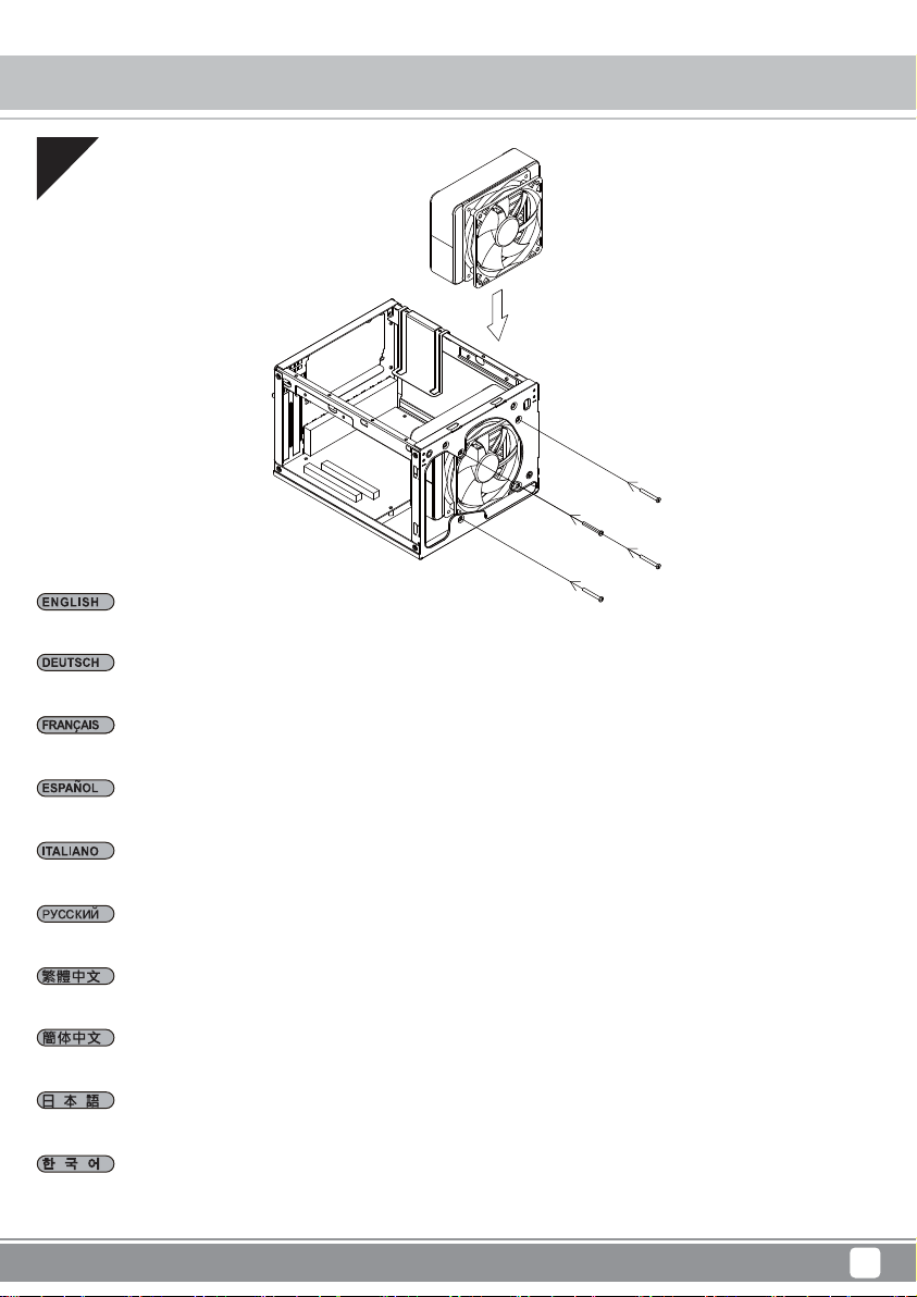
06
If you wish to use all-in-one liquid cooler or a front fan, please install it now.
SUGO Series SG13
Installation Chart
Wenn Sie einen Alles-in-Einem-Flüssigkeitskühler oder einen frontseitigen Lüfter nutzen möchten, installieren Sie diesen bitte jetzt.
Si vous souhaitez utiliser le refroidisseur liquide tout-en-un ou un ventilateur en façade, veuillez l'installer à présent.
Si desea usar refrigeración líquida multifunción o un ventilador frontal, por favor instálelos ahora.
Se si vuole utilizzare un sistema di raffreddamento a liquido all-in-one, oppure una ventola frontale, eseguirne adesso l’installazione.
Если вы собираетесь использовать моноблочный кулер с жидкостным охлаждением или передний вентилятор, сразу установите его.
如果您需要安装一体式水冷或前风扇,建议您于此时安装。
如果您需要安裝一體式水冷或前風扇,建議您於此時安裝。
オールインワン液冷クーラーまたはフロントファンを利用される場合、この時点でインストールします。
일체형 수냉식 쿨러 또는 전면 팬을 사용하려면, 지금 이를 설치하십시오.
9
Page 12

SUGO Series SG13
Installation Chart
07
Connect all front I/O connectors.
Verbinden Sie alle frontseitigen Ein-/Ausgänge.
Connectez tous les connecteurs d'E/S en façade.
Conecte todos los conectores frontales E/S.
Collegare tutti i connettori I/O frontali.
Подключите все разъемы ввода/вывода на передней панели.
建議您此時連接前置I/O線材。
建议您此时连接前置I/O线材。
すべてのフロントI/Oコネクタを接続します。
모든 전면 I/O 커넥터를 연결합니다.
10
Page 13

SUGO Series SG13
Installation Chart
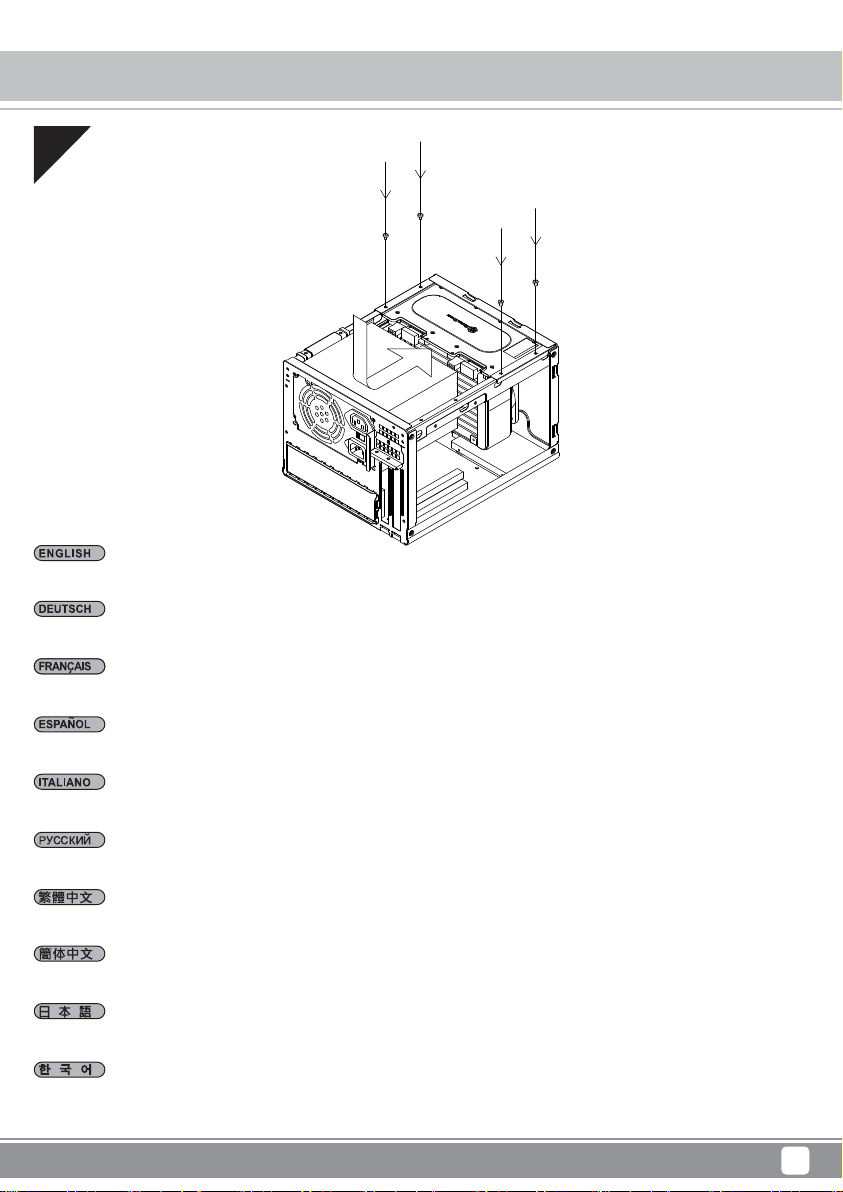
08
Due to limited internal space between expansion card and power supply area, we recommend to install power supply into the chassis before expansion
card.
Aufgrund des beschränkten Platzes zwischen Erweiterungskarte und Netzteilbereich sollten Sie das Netzteil vor der Erweiterungskarte im Gehäuse
installieren.
En raison de la limite d'espace interne entre la carte d'extension et la zone du bloc d'alimentation, nous vous recommandons d'installer l'alimentation
dans le châssis avant la carte d'extension.
Debido al límite del espacio interno entre la tarjeta de expansión y la zona de la fuente de alimentación, le recomendamos instalar la fuente de
alimentación en el chasis antes de la tarjeta de expansión.
A causa dello spazio interno limitato tra la scheda di espansione e l’area dell’alimentatore, si raccomanda di installare nel telaio prima l'alimentatore
e poi la scheda di espansione.
Ввиду ограниченности пространства между картой расширения и зоной блока питания мы рекомендуем сначала установить блок питания
в корпус, а затем карту расширения.
請先將電源供應器安裝至機殼。由於機殼內部安裝空間有限,顯示卡與電源供應器距離過近,不建議您先安裝顯示卡。
请先将电源供应器安装至机壳。由于机壳内部安装空间有限,显示卡与电源供应器距离过近,不建议您先安装显示卡。
拡張カードと電源の間のスペースが限られているので、拡張カードの前にケースに電源をインストールするようお勧めします。
확장 카드와 전원 공급장치 영역 간의 내부 공간이 제한되어 있기 때문에, 당사에서는 먼저 전원 공급장치를 섀시에 설치한 후 확장 카드를 나중에
설치할 것을 권장합니다.
11
Page 14

SUGO Series SG13
Installation Chart
09
Install 2.5” or 3.5” drives into drive cage.
Installieren Sie 2,5 / 3,5-Zoll-Festplatten im Festplattenkäfig.
Installez les disques 2,5" / 3,5" dans la cage des lecteurs.
Instale los dispositivos de 2,5” / 3,5” en la carcasa para dispositivos.
Installare le unità da 2,5” / 3,5” nella gabbia del disco rigido.
Установите в отсек приводов 2,5-дюймовые / 3,5-дюймовые диски.
將2.5吋或3.5吋硬碟安裝至硬碟架。
将2.5吋或3.5吋硬盘安装至硬盘架。
ドライブケージに2.5"/3.5"ドライブをドライブケージにインストールします。
2.5” / 3.5” 드라이브를 드라이브 케이지에 설치합니다.
12
Page 15
10
Reinstall completed drive cage assembly back into the chassis.
SUGO Series SG13
Installation Chart
Bringen Sie den bestückten Festplattenkäfig wieder im Gehäuse an.
Réinstallez l'ensemble de la cage avec les lecteurs dans le châssis.
Reinstale la carcasa para dispositivos con el montaje completo de nuevo en el chasis.
Reinstallare nel telaio la gabbia con disco rigido.
Установите заполненный отсек приводов обратно в корпус.
將硬碟架連同硬碟裝回機殼。
将硬盘架连同硬盘装回机壳。
組立てられたドライブケージアセンブリをケースへ戻します。
완료된 드라이브 케이지 어셈블리를 섀시에 도로 설치합니다.
13
Page 16

SUGO Series SG13
Installation Chart
11
Connect all remaining cables.
Schließen Sie alle restlichen Kabel an.
Connectez tous les câbles restants.
Conecte todos los cables restantes.
Collegare tutti i cavi rimanenti.
Подключите остальные кабели.
連接所有排線。
连接所有扁平电缆。
残りのケーブルを全て接続します。
남아 있는 모든 케이블을 연결합니다.
14
Page 17

SUGO Series SG13
Installation Chart
12
Install graphics or expansion card as needed. If the card you wish to use is too long to fit through the side of the chassis, you can alternatively install
it through the front panel of the case.
Installieren Sie nach Erforderlichkeit eine Grafik- oder Erweiterungskarte. Falls die Karte, die Sie nutzen möchten, aufgrund ihrer Länge nicht durch
die Seite des Gehäuses passt, können Sie sie alternativ durch die Frontblende des Gehäuses installieren.
Installez les cartes graphique ou d'extension si nécessaire. Si la carte que vous souhaitez utiliser est trop longue pour tenir sur le côté du châssis,
vous pouvez également l'installer via le panneau avant du boîtier.
Instale la tarjeta gráfica o de expansión según sea necesario. Si la tarjeta que desea usar es demasiado larga para pasar a través del lateral del
chasis, como alternativa puede instalarla a través del panel frontal de la carcasa.
Installare scheda video o la scheda di espansione come necessario. Se la scheda che si vuole utilizzare è troppo lunga da montare lungo il lato del
telaio, è possibile anche installarla dal pannello frontale del case.
При необходимости установите графическую карту или карту расширения. Если устанавливаемая карта слишком длинная и не проходит
через боковую сторону корпуса, ее можно установить через лицевую панель.
安裝顯示卡或擴充卡,如果顯示卡長度太長難以從側邊放入機殼,建議您可以從前面放入。
安装显示卡或扩充卡,如果显示卡长度太长难以从侧边放入机壳,建议您可以从前面放入。
必要に応じてグラフィックスまたは拡張カードを装着します。使用するカードがケース側面からは長過ぎて入らない場合、ケースのフロントパネ
ルからインストールすることができます。
필요한 경우 그래픽 카드 또는 확장 카드를 설치합니다. 사용하려는 카드가 너무 길어 섀시의 측면을 통해 넣을 수 없는 경우, 케이스의 전면 패널을
통해 이를 설치할 수 있습니다.
15
Page 18

SUGO Series SG13
Installation Chart
13
Close the front panel.
Schließen Sie die Frontblende.
Fermez le panneau frontal.
Cierre el panel frontal.
Chiudere il pannello frontale.
Закройте лицевую панель.
蓋上前面板。
盖上前面板。
フロントパネルを閉じます。
전면 패널을 닫습니다.
16
Page 19

14
Re-install expansion card slot holder and secure with screws.
SUGO Series SG13
Installation Chart
Bringen Sie die Halterung des Erweiterungskartensteckplatzes wieder an und befestigen Sie sie mit Schrauben.
Réinstallez le support de l'emplacement de la carte d'extension et fixez-le avec des vis.
Reinstale el enganche del zócalo de la tarjeta de expansión y fíjelo con tornillos.
Reinstallare il supporto dell’alloggio per schede di espansione e fissarlo con le viti.
Установите фиксатор слота карты расширения на место и закрепите винтами.
請裝回顯示卡槽檔板並以螺絲鎖固。
请装回显示卡槽档板并以螺丝锁固。
拡張カード・スロットホルダーを戻してから、ネジで固定します。
확장 카드 슬롯 홀더를 도로 설치하고 나사를 사용하여 고정합니다.
17
Page 20

SUGO Series SG13
Installation Chart
15
Make sure again that all cables and connectors are installed, then remount the top cover and secure with screws.
Stellen Sie sicher, dass alle Kabel und Anschlüsse installiert sind; bringen Sie die obere Abdeckung dann wieder an und befestigen Sie sie mit
Schrauben.
Assurez-vous de nouveau que tous les câbles et connecteurs sont installés, puis remontez le capot supérieur et fixez-le avec des vis.
Asegúrese de nuevo de que todos los cables y conectores están instalados, luego vuelva a montar la cubierta superior y fíjela con tornillos.
Assicurarsi ancora una volta che tutti i cavi ed i connettori siano stati installati, quindi rimettere il coperchio superiore e fissarlo con le viti.
Проверьте подключение всех кабелей и разъемов, после чего установите верхнюю крышку и закрепите ее винтами.
請確認所有必需線材與線路都已連接後,將上蓋裝回機殼並以螺絲鎖固。
请确认所有必需线材与线路都已连接后,将上盖装回机壳并以螺丝锁固。
全てのケーブルとコネクタが装着されていることをもう一度確認してから、トップカバーを戻し、ネジで固定します。
모든 케이블과 커넥터가 설치되었는지 다시 확인한 후, 상부 커버를 도로 장착하고 나사로 고정합니다.
18
Page 21

16
Installation complete.
SUGO Series SG13
Installation Chart
Damit ist die Installation abgeschlossen.
L'installation est terminée.
Instalación completa.
L'installazione è completata.
Установка завершена.
安裝完成
安装完成
インストール完了。
설치가 완료되었습니다.
19
Page 22

SUGO Series SG13
Connector Definition
(1) Front Panel Connectors
A.Power switch and reset switch installation guide:
Please refer to the motherboard manuals for the motherboard’s “Front Panel Connector” or “System Panel Connector” pin definitio
Power switch and reset switch have no polarity, so they can be connected in any orientation.
Bitte suchen Sie in der Motherboard-Dokumentation nach der Pinbelegung der Anschlüsse des Frontbedienfeldes („Front Panel Conne
oder „ System Panel Connectors“). Ein-/Austaste und Rücksetztaste benötigen keine bestimmte Polarität, können daher beliebig (o
und - zu achten) angeschlossen werden.
Veuillez-vous référer au manuel de votre carte mère pour la description des broches "des connecteurs du panneau frontal" et des
"des connecteurs du panneau système". Les interrupteurs d'allumage et de réinitialisation ne possède pas de polarité, donc ils peuvent être
branché dans les deux sens.
Por favor, consulte en los manuales de la placa base la configuración de pines del “Conector de panel frontal” ó “Conector de panel de sistema”
de su placa base. Los interruptores de encendido y reseteo no tienen polaridad, luego se pueden conectar con cualquier orientac
Fare riferimento al manuale della scheda madre nella sezione “Connettori del pannello frontale” o “Connettori del pannello di sistema”. Power
switch e reset switch non hanno polarità, posso essere pertanto connessi con qualsiasi orientamento.
Описание контактов разъемов приведены в разделах “Разъемы передней панели” или “Разъемы системной панели” руководства
пользователя материнской платы. Выключател ь питания и кнопка перезагрузки не имеют полярности, поэтому их можно подключать
в любой ориентации.
메인보드 매뉴얼의 전면패널 커넥터 혹은 시스템패널 커넥터 핀을 참조하기 바랍니다. 파워 스위치와 리셋 스위치는 극 성이 없어 어떤
방향으로 설치해도 무방합니다.
マザーボードの「フロントパネルコネクタ」または「システムパネルコネクタ」のピン配列についてはマザーボードマニュアルを参照してください。
電源スイッチとリセットスイッチに極性はないので、いずれの方向でも接続できま。
請參考主機說明書的Front Panel Connectors安裝Pin Define,將Connector插上;Power Switch 與Reset Switch並無正負極性之分,
反插正插都不影響功能性。
请参考主机说明书的Front Panel Connectors安装Pin Define,将Connector插上;Power Switch 与Reset Switch
反插正插都不影响功能性。
并无正负极性之分,
20
Page 23

SUGO Series SG13
Connector Definition
(1) Front Panel Connectors
B:LED indicators installation guide
Please refer to the motherboard manuals for the motherboard’s “Front Panel Connector ” or “System Panel Connector” pin definition.; the white/black
wires are negative while other colors are positive wires. The Power LED wires are separate pins for compatibility with different motherboard pin
definition so please make sure they are connected in the right polarity by referring to your motherboard manual.
Bitte suchen Sie in der Motherboard-Dokumentation nach der Pinbelegung der Anschlüsse des Frontbedienfeldes („Front Panel Connectors“ oder „
System Panel Connectors“). Die weißen/ schwarz Adern sind negativ (-), die farbigen Adern positiv (+).Die Kabel für die Betriebsanzeige-LED sind
zur Kompatibilität mit unterschiedlichsten Motherboards einzeln, nicht als kompletter Stecker ausgeführt. Achten Sie hier bitte auf die richtige
Polarität, lesen Sie in der Dokumentation Ihres Motherboards nach.
Veuillez-vous référer au manuel de votre carte mère pour la description des broches "des connecteurs du panneau frontal" et des broches "des connecteurs du panneau
système". Les câbles colorés en blanc/noir sont négatifs alors que ceux d'une autre couleur sont positifs. Les câbles de la LED Power sont séparés afin d'être compatible
avec différentes cartes mères, donc vérifiez bien qu'ils sont branchés avec la bonne polarité en vous référant au manuel de votre carte mère
Por favor, consulte en los manuales de la placa base la configuración de pines del “Conector de panel frontal” ó “Conector de panel de sistema” de
su placa base. Los cables de color blanco/negro son negativos mientras que los de color son positivos. Los cables LED de potencia tienen pines
separados para compatibilidad con diferentes definiciones de pines de la placa base luego por favor, asegúrese de que están conectados en la
polaridad correcta consultando el manual de su placa base.
Fare riferimento al manuale della scheda madre nella sezione “Connettori del pannello frontale” o “Connettori del pannello di sistema”. I cavi di
colore bianco/nero sono il polo negativo, mentre quelli di colore diverso il positivo.
Описание контактов разъемов приведены в разделах “Разъемы передней панели” или “Разъемы системной панели” руководства
пользователя материнской платы. Белые/черный провода - отрицательной полярности, цветные провода - положительной полярности.
Провода светодиодного индикатора питания имеют отдельные контакты для совместимости с различными типами контактов материнских
плат, поэтому обратитесь к руководству пользователя материнской платы и убедитесь, что полярность соблюдена.
메인보드 매뉴얼의 전면패널 커넥터 혹은 시스템패널 커넥터 핀을 참조하기 바랍니다. 하얀/검은선의 경우 음극이며, 다른 색의 경우
양극입니다. 파워 LED 선은 분리되어 다양한 메인보드에서 동작할 수 있도록 되어 있습니다. 그러므로 메인보드 매뉴얼을 참조하여 올바를
극성을 주의해 선택하시기 바랍니다.
マザーボードの「フロントパネルコネクタ」または「システムパネルコネクタ」ピン配列についてはマザーボードマニュアルを参照してください。
白/黑色のリード線はマイナスで、色の着いたリード線がプラスです。電源LEDリード線は種々のマザーボードピン定義と互換性を持たせるため分離されたピ
ンとなっているので、ご使用のマザーボードマニュアルを参照して、適切な極性に接続されるようお確かめください。
請參考主機說明書的Front Panel Connectors安裝Pin Define,將Connector插上;白/黑色線的部分為負極,彩色線的部分是正極。
Power LED為了適應各主機板的不同, 特別設計為散Pin樣式,請安心使用。
请参考说明书的Front Panel Connectors安装Pin Define,将Connector插上;白/黑色线的部份为负极,彩色线的部份为正极。
Power LED为了适应主机板的不同, 特别设计为散Pin样式,请安心使用。
21
Page 24

SUGO Series SG13
Connector Definition
(2) Front I/O connector guide
Below are the front I/O connectors pin definition, please also check your motherboard manual to cross reference with motherboard’s
front I/O pin headers. SilverStone’s I/O connectors are in block type to simplify installation.
Nachstehend finden Sie die Pinbelegung der vorderen E/A-Anschlüsse; bitte gleichen Sie zudem das Handbuch Ihres Motherboards mit
den vorderen E/A-Pinzuweisungen ab. SilverStones E/A-Anschlüsse befinden sich zur Vereinfachung der Installation in Blockart.
Au dessous de la description des broches des ports d'E/S, veuillez aussi vérifier sur le manuel de votre carte mère de manière croisée
que les broches sont correctement placées. Les connecteurs d'E/S de SilverStone sont en bloc pour en simplifier leur installation.
A continuación tiene la definición de pines de los conectores frontales de E/S, también debe consultar el manual de su placa base para c
omprobar la referencia de los pines para E/S frontales. Los conectores de E/S de SilverStone son de bloque para simplificar la instalación.
Di seguito lo schema delle connessioni I/O frontali, confrontare lo schema con quanto riportato sul manuale della scheda madre per
effettuare una controllo incrociato. I connettori I/O Silverstone, per semplificare l’installazione, sono del tipo “a blocco”.
Ниже приведено описание контактов передних разъемов ввода/вывода. Обратитесь также к руководству пользователя материнской
платы за описанием передних разъемов ввода/вывода типа "пин-хедер". Разъемы ввода/вывода "SilverStone" - блочного типа, что
облегчает сборку.
아래는 전면 I/O 커넥터의 핀 설정이며, 메인보드 매뉴얼을 참조해 메인보드의 전면 I/O 핀 헤더와 맞추어 설치합니다.
Silverstone의 I/O 커낵터는 블록 타이브로 구성되어 설치를 간편화 했습니다.
以下はフロントI/Oコネクタピン配列ですが、お持ちのマザーボードのフロントI/Oピンヘッダは、マザーボードマニュアルをご参照ください。
シルバーストーンのI/Oコネクタは、インストールの容易なブロックタイプになっています。
下表為Front I/O Connectors的Pin Define,請參閱主機板說明書的各Front I/O Connectors Pin Define一一核對。
Front I/O Connectors完全採用集合Pin方式以簡化安裝。
下表为Front I/O Connectors的Pin Define,请参阅主机板说明书的各Front I/O Connectors Pin Define一一核对。
Front I/O Connectors完全采用集合Pin方式以简化安装。
USB 3.0 CONNECTOR HD CONNECTOR
Pin 1
Vbus
IntA_P1_SSRX-
IntA_P1_SSRX+
GND
IntA_P1_SSTX-
IntA_P1_SSTX+
GND
IntA_P1_D-
IntA_P1_D+
ID
Pin 19
Vbus
IntA_P2_SSRXIntA_P2_SSRX+
GND
IntA_P2_SSTXIntA_P2_SSTX+
GND
IntA_P2_DIntA_P2_D+
AUD GND
PRESENCE
SENSE1_RETURN
PIN
SENSE2_RETURN
PORT1L
PORT1R
PORT2R
SENSE_SEND
PORT2L
Pin 11Pin 10
22
Pin
Page 25

SUGO Series SG13
Component Size Limitations
SG13 is a small form factor (SFF) case, we recommend the following guidelines for assembly or future upgrades.
(1) CPU cooler height limitation
A. Air cooling
8mm
61mm
CPU cooler height limitation:The SG13 has 61mm height limitation for CPU cooler.
Upper boundary:The cooler can protrude 8mm over the motherboard edge.
Front boundary:Cooler can protrude from motherboard edge by 90mm without system fan installed.
Höhenbeschränkung:Das SG13 unterstützt beim CPU-Kühler eine Maximalhöhe von 61 mm.
Obere Grenze:Der Kühler kann 8 mm über die Motherboard-Oberkante hinausstehen.
Vordere Grenze:Der Kühler kann um 90 mm über die Motherboard-Kante hinausragen, wenn kein Systemlüfter installiert ist.
Limitation de la hauteur:The SG13 has 61mm height limitation for CPU cooler.
Limite supérieure:The cooler can protrude 8mm over the motherboard edge.
Limite frontale:Le système de refroidissement peut dépasser du bord de la carte mère de 90 mm, sans ventilateur installé.
Limitación de altura:La SG13 tiene una limitación de altura de 61mm para el disipador de la CPU.
Límite superior:El disipador puede sobresalir 8mm del borde de la placa base.
Límite frontal:El disipador puede sobresalir del borde de la placa base 90mm sin tener instalado el ventilador del sistema.
Limitazioni dell’altezza:In SG13 l’altezza del dissipatore CPU è limitata a 61 mm.
Limite superiore:Il dissipatore può sporgere 8 mm dai bordi della scheda madre.
Limite anteriore:Il dispositivo di raffreddamento può sporgere di 90 mm dal bordo della scheda madre senza ventola di sistema installata.
Ограничение по высоте::В корпус SG13 можно установить процессорный кулер высотой не более 61 мм.
Верхний край:Вентилятор может выступать за край системной платы на 8 мм.
Передний край:Если не установлен вентилятор системы, кулер может выступать от края системной платы на 90 мм.
높이 제한:SG13은 CPU쿨러의 높이 제한이 61mm 입니다.
단 경계:쿨러는 메인보드 가장자리로 부터 8mm 정도 나와도 무방합니다.
전면 경계:쿨러는 시스템 팬이 설치되지 않은 상태에서 메인보드 가장자리로부터 90mm 돌출될 수 있습니다.
高さ制限:SG13はCPUクーラーを対照として61mmの高さ制限があります。
上方の限界:クーラーはマザーボードエッジから8mm突出させることができます。
正面の限界:システムファンを装着しない場合、クーラーはマザーボード端面から90mmまで突出できます。
90mm
高度限制:Cooler限高是61mm。
上邊界:Cooler外緣允許超出主機板上邊界8mm。
前邊界:沒有安裝系統風扇為前提下,Cooler允許超出主機板前方90mm。
高度限制:Cooler限高是61mm。
上边界:Cooler外缘允许超出主板上边界8mm。
前边界:没有安装系统风扇为前提下,Cooler允许超出主板前方90mm。
23
Page 26

SUGO Series SG13
Component Size Limitations
B. Liquid cooling
90mm
The maximum thickness for radiator plus fans is 90mm. When using coolers such as SilverStone’s TD03, we recommend installing only one fan
with it. To reduce interference of tubing against the motherboard, the radiator should be installed in front of the fan. Installing larger 140mm based
radiator will require the removal of the upper drive cage and sacrifice to available room for graphics card. The maximum allowable length for graphics
card with a 140mm fan or radiator is 264mm (10.39”) minus the thickness of the fan and/or radiator.
Die maximale Dicke von Kühlkörper und Lüfter beträgt 90 mm. Wenn Sie Kühler wie SilverStones TD03 nutzen, sollten Sie nur einen Lüfter damit
installieren. Damit die Verschlauchung dem Motherboard nicht ins Gehege kommt, sollte der Kühlkörper vor dem Lüfter installiert werden. Die
Installation eines größeren 140-mm-basierten Kühlkörpers setzt voraus, dass Sie den oberen Festplattenkäfig entfernen und auf mehr Platz für die
Grafikkarte verzichten. Die maximal erlaubte Grafikkartenlänge mit einem 140-mm-Lüfter oder -Kühlkörper beträgt 264 mm (10,39 Zoll) abzüglich
der Dicke des Lüfters und/oder Kühlkörpers.
L'épaisseur maximale du radiateur avec les ventilateurs est de 90 mm. Lors de l'utilisation de refroidisseurs tels que le TD03 de Silverstone, nous
vous conseillons de n'installer qu'un seul ventilateur. Pour réduire les interférences des tubes contre la carte mère, le radiateur doit être installé à
l'avant du ventilateur. L'installation d'un radiateur plus large avec une base de 140 mm nécessite de retirer la cage de disques supérieure et de
sacrifier l'espace disponible pour la carte graphique. La longueur maximale admissible pour la carte graphique avec un ventilateur de 140 mm ou
un radiateur est de 264 mm (10,39") moins l'épaisseur du ventilateur et / ou du radiateur.
El grosor máximo para el radiador más ventilador es de 90mm. Cuando usa disipadores como el SilverStone TD03, le recomendamos instalar solo
un ventilador con él. Para reducir la interferencia de los tubos contra la placa base, el radiador debería instalarse frente al ventilador. Instalar un
radiador con una base mayor de 140mm precisará de quitar la carcasa para dispositivos superior y sacrificar el espacio disponible para las tarjetas
gráficas. La longitud máxima permitida para las tarjetas gráficas con un ventilador o radiador de 140mm es 264mm (10,39”) menos el grosor del
ventilador y/o radiador.
264mm
Lo spessore massimo del radiatore con ventole è di 90 mm. Quando si utilizzano dispositivi di raffreddamento come TD03 di SilverStone, si
raccomanda di installare una sola ventola. Per ridurre l'interferenza delle tubazioni contro la scheda madre, il radiatore deve essere installato davanti
alla ventola. L’installazione di radiatori con base maggiore di 140 mm richiede la rimozione della gabbia del disco rigido superiore e di sacrificare
lo spazio a disposizione per la scheda video. La lunghezza massima consentita per la scheda video con una ventola da 140 mm o radiatore è di
264 mm (10,39") meno lo spessore della ventola e/o radiatore.
Максимальная толщина радиатора вместе с вентиляторами составляет 90 мм. При использовании таких кулеров, как TD03 компании
SilverStone, мы рекомендуем устанавливать только один вентилятор. Чтобы трубки кулера не соприкасались с системной платой, радиатор
следует устанавливать перед вентилятором. При установке радиатора размером более 140 мм потребуется извлечь верхний отсек
приводов, чтобы обеспечить достаточный объем пространства для графической карты. Максимальная длина графической карты при
использовании 140-миллиметрового вентилятора или радиатора составляет 264 мм (10,39 дюйма) минус толщина вентилятора и/или
радиатора.
라디에이터와 팬을 합친 최대 두께는 90mm입니다. SilverStone의 TD03과 같은 쿨러를 사용하는 경우, 당사에서는 쿨러에 팬을 한 개만 설치할 것을
권장합니다. 메인보드와 배선 간의 간섭을 줄이려면, 라디에이터를 팬 앞에 설치해야 합니다. 대형 140mm 기반 라디에이터를 설치하려면 상단
드라이브 케이지를 제거하고 그래픽 카드를 설치할 수 있는 공간을 없애야 합니다. 140mm 팬 또는 라디에이터에서 그래픽 카드에 대해 허용할 수
있는 최대 길이는 264mm(10.39”)에서 팬 및/또는 라디에이터의 두께를 뺀 길이입니다.
ラジエターとファンの厚さ合計は最大90mmです。SilverStone製TD03などの使用時には、1台のファンのみ装着するようお勧めします。チューブ
の取り回しがマザーボードの邪魔にならないよう、ラジエターはファンの前方に設置してください。大型の140mmベースのラジエターでは、上
部ドライブケージの取り外しが必要となり、グラフィックスカードの利用できるスペースが犠牲になります。140mmファンまたはラジエター装
着時のグラフィックスカード最大許容長さは264mm (10.39”)からファンやラジエターの長さを差し引いた長さとなります。
水冷排與風扇加總厚度上限為90mm,使用銀欣TD03時,我們建議你只安裝一顆風扇。如果擔心水管干涉主機板元件,建議您可以將水冷排放在風
扇前面來安裝。若欲安裝140規格水冷,必須犧牲上層的所有硬碟與顯示卡長度,顯示卡長度只剩264mm(10.39”)另外再扣除水冷排與風扇的厚度。
水冷排与风扇加总厚度上限为90mm,使用银欣TD03时,我们建议你只安装一颗风扇。如果担心水管干涉主板组件,建议您可以将水冷排放在风扇
前面来安装。若欲安装140规格水冷,必须牺牲上层的所有硬盘与显示卡长度,显示适配器长度只剩264mm(10.39”)另外再扣除水冷排与风扇的厚度。
24
Page 27

SUGO Series SG13
Component Size Limitations
(2) PSU limitation
Maximum depth for a standard PS/2 (ATX) power supply is 150mm. Models with modular cables may or may not fit depending on connector locations.
If upper drive cage is removed, there is nearly no limit to power supply depth, pending the thickness of the fan or radiator used on the front panel.
The table shows power supply we have tested:
Die maximale Tiefe eines standardmäßigen PS/2(ATX)-Netzteils beträgt 150 mm. Ob Modelle mit modularen Kabeln passen, hängt von der
Anschlussposition ab.
Wenn der obere Festplattenkäfig entfernt wird, gibt es – abhängig von der Dicke des an der Frontblende verwendeten Lüfters oder Kühlkörpers –
nahezu keine Beschränkung bezüglich der Netzteildicke.
Die nachstehende Tabelle zeigt Netzteile, die wir getestet haben:
La profondeur maximale pour un bloc d'alimentation standard PS/2 (ATX) est de 150 mm. Les modèles avec des câbles modulaires peuvent
convenir ou non selon l'emplacement des connecteurs.
Si cage des disques supérieure est retirée, il n'y a presque pas de limite à la profondeur de l'alimentation, selon l'épaisseur du ventilateur ou du
radiateur utilisé sur le panneau frontal.
Le tableau indique les blocs d'alimentation que nous avons testés :
La profundidad máxima para una fuente de alimentación PS/2 (ATX) estándar es 150mm. Los modelos con cables modulares podrían o no encajar
dependiendo de la posición de los conectores.
Si la carcasa superior de dispositivos se retira, casi no hay límites para la profundidad de la fuente de alimentación, dependiendo del grosor del
ventilador o radiador usado en el panel frontal.
La tabla muestra las fuentes de alimentación que hemos probado:
La profondità massima per un alimentatore PS/2 (ATX) standard è di 150 mm. I modelli con cavi modulari possono non adattarsi in base alla
posizione dei connettori.
Se la gabbia del disco rigido superiore è rimossa, non c’è quasi limite alla profondità dell’alimentatore, fermo restando lo spessore della ventola o
del radiatore utilizzato sul pannello frontale.
La tabella mostra gli alimentatori che sono stati testati:
Максимальная глубина стандартного блока питания PS/2 (ATX) составляет 150 мм. Модели с модульными кабелями могут подойти или не
подойти, в зависимости от расположения разъемов.
Если извлечен верхний отсек дисков, ограничений по глубине блока питания практически нет, в зависимости от толщины вентилятора или
радиатора, используемого на лицевой панели.
В таблице ниже приведены протестированные нами блоки питания:
140mm 264mm
표준 PS/2(ATX) 전원 공급장치의 최대 깊이는 150mm입니다. 모듈식 케이블이 있는 모델은 커넥터 위치에 따라 맞을 수도 맞지 않을 수도
있습니다.
상단 드라이브 케이지를 제거하면, 전면 패널에 사용된 팬 또는 라디에이터의 두께에 따른 전원 공급장치의 깊이에 거의 한계가 없습니다.
다음은 테스트를 마친 전원 공급장치의 표입니다.
標準PS/2(ATX)電源の最大奥行きは150mmです。モジュラーケーブル付きのタイプは、コネクタの場所によっては設置できない物があります。
上部ドライブケージを外した場合は、フロントパネルに装着したファンまたはラジエターの厚さに依存するものの、電源の奥行きにはその他制
限はありません。
下表には当社のテストした電源が示されています。
SG13限定使用長度為150mm以內的標準ATX電源。
模組化電源的插座會與主磁架安裝的硬碟有關,不一定能相容。
下表是我們測試過的模組化電源,如果不安裝上層硬碟架,電源供應器長度則幾乎無限制,此時電源供應器與水冷排加上風扇厚度加總限制在264mm以內。
SG13限定使用长度为150mm以内的标准ATX电源。
模块化电源的插座会与主磁架安装的硬盘有关,不一定能兼容。
下表是我们测试过的模块化电源,如果不安装上层硬盘架,电源供应器长度则几乎无限制,此时电源供应器与水冷排加上风扇厚度加总限制在264mm以内。
140mm, ST50F-P/ST60F-PS/ST65f-G
150mm, ST75F-GS/ST85F-GS
2.5” x 2
OK
Requires SilverStone CP11 cableOKOK
3.5”
25
Page 28

SUGO Series SG13
Component Size Limitations
(3) Graphics card length limit
10.5”
SG13 can support graphics card up to 10.5” (267mm) long.
Das SG13 kann Grafikkarten mit einer Länge bis 267 mm (10,5 Zoll) unterstützen
Le SG13 peut prendre en charge une carte graphique jusqu'à 10,5" (267 mm) de long.
La SG13 puede aceptar tarjetas gráficas de hasta 10,5” (267mm) de largo
SG13 supporta schede video lunghe fino a 10,5” (267 mm)
В корпус SG13 допускается установка графических карт длиной до 10,5 дюйма (267 мм).
SG13은 최대 10.5”(267mm) 길이의 그래픽 카드를 지원할 수 있습니다.
SG13は、最大10.5” (267mm)長のグラフィックスカードに対応します。
SG13最长可支持至10.5吋的显示卡。
SG13最長可支援至10.5吋的顯示卡。
26
Page 29

Fan removal steps
01
SUGO Series SG13
Upgrade And Maintenance
02
Remove front panel
Entfernen Sie die Frontblende.
Enlevez le panneau frontal.
Retire el panel frontal.
Rimuovere il pannello frontale.
Unscrew screws holding the
fans to remove them.
Снимите лицевую панель.
拆除前面板
拆除前面板
フロントパネルを取り外します。
전면 패널을 분리합니다.
Отверните винты крепления
вентилятора и извлеките его.
Lösen Sie die Fixierschrauben
des Lüfters und nehmen Sie
den Lüfter heraus.
Dévissez les vis du ventilateur
pour l'enlever.
Afloje los tornillos que sujetan
el ventilador para retirarlo.
Allentare le viti che fissano la
ventola per rimuoverla.
拆除風扇螺絲,取下風扇
拆除风扇螺丝,取下风扇
ファンを固定しているネジを外
してファンを取り外します。
팬을 고정하는 나사를 풀어 팬을
분리합니다.
27
Page 30

SUGO Series SG13
Upgrade And Maintenance
SG13
’s positive air pressure design is an effective configuration that will reduce dust buildup inside the case. Small air particles or lint will
accumulate over time on intake filters instead of on the components inside the case. To maintain
to come, we recommend to clean all fan filters regularly every three months or half a year (depending on your environment). Below are steps to
remove fan filters.
SG13
Das vorteilhafte Luftdruckdesign des
der Zeit sammeln sich kleine Partikel und Fusseln an den Luftzufuhrfiltern, anstatt an den Komponenten im Gehäuseinneren, an. Sie können eine
jahrelange optimale Kühlleistung des
Umgebungsbedingungen). Nachstehend finden Sie die Schritte zur Entfernung der Lüfterfilter.
ist eine effektive Konfiguration, die Staubablagerungen innerhalb des Gehäuses vermindert. Im Laufe
SG13
gewährleisten, indem Sie alle Lüfterfilter regelmäßig alle drei bis sechs Monate reinigen (je nach
SG13
’s excellent cooling performance for years
La conception à pression d'air positive du
De petites particules d'air ou de peluche vont s'accumuler avec le temps sur les filtres d'aspiration, et non sur les composants à l'intérieur du boîtier.
Pour conserver les excellentes performances de refroidissement du
filtres des ventilateurs, tous les trois ou six mois (selon votre environnement). Vous trouverez ci-dessous les étapes vous expliquant comment retirer
les filtres des ventilateurs.
El diseño de presión de aire positiva de la
Pequeñas partículas de polvo ó pelusa se irán acumularán con el transcurso del tiempo en los filtros de entrada en lugar de en los componentes
del interior de la carcasa. Para mantener la excelente capacidad de refrigeración de la
con regularidad todos los filtros de los ventiladores cada tres meses ó seis meses (dependiendo de dónde viva). A continuación están los pasos
para quitar los filtros de los ventiladores.
Il design a pressione positiva di
infatti sui filtri invece che sui componenti interni. Per mantenere le eccellenti prestazioni di raffreddamento di
raccomandiamo di procedere ad una regolare pulizia dei filtri (con cadenza trimestrale o semestrale dipendentemente dall’ambiente un cui è
disposto il sistema). Di seguito i passi per la rimozione dei filtri.
Конструкция корпуса
препятствующую скоплению пыли внутри корпуса. Небольшие частицы и волокна, содержащиеся в воздухе, со временем будут
скапливаться на впускных фильтрах, а не на компонентах, находящихся внутри корпуса. Для поддержания превосходного охлаждения
компонентов в корпусе
раз в полгода (в зависимости от условий окружающей среды). Ниже приведена процедура для удаления фильтров вентиляторов.
SG13
的正壓差搭配濾網方式是經的起時間考驗最有效的防塵方式。在使用相當長一段時間後,棉屑灰塵或其他可能妨礙散熱效能的小異物只會卡在濾
網,而不是電腦內的元件上面。我們重視的散熱效能,是在您使用電腦長達2~3年後還能維持與全新的無異。為了維持這種散熱效能您只需要定期清理濾
網,而不是電腦裡面的元件。視環境而定,我們建議您每6個月~1年必須清理濾網,以下是濾網的拆卸步驟。
SG13
的正压差搭配滤网方式是经的起时间考验最有效的防尘方式。在使用相当长一段时间后,棉屑灰尘或其它可能妨碍散热效能的小异物只会卡在
滤网,而不是计算机内的组件上面。我们重视的散热效能,是在您使用计算机长达2~3年后还能维持与全新的无异。为了维持这种散热效能您只需要定
期清理滤网,而不是计算机里面的组件。视环境而定,我们建议您每6个月~1年必须清理滤网,以下是滤网的拆卸步骤。
SG13
の正圧設計は、ケース内のホコリの蓄積を減少させる有効な構造です。時と共に空気中の微粒子または糸くずはケース内のコンポーネト
上の代わりに取入れ口フィルタに溜まります。この先何年もの間
環境に依存) ごとに規則的に清掃するようお勧めします。以下は、ファンフィルタを取り外す手順です。
SG13
SG13
SG13
est une configuration efficace permettant de réduire l'accumulation de la poussière dans le boîtier.
SG13
au fil des ans, nous vous recommandons de nettoyer l'ensemble des
SG13
es una configuración efectiva que reducirá la acumulación de polvo dentro de la carcasa.
SG13
en años venideros, le recomendamos que limpie
SG13
riduce considerevolmente gli accumuli di polvere all’interno del case. Le piccole particelle si accumulano
обеспечивает избыточное давление воздуха и, таким образом, имеет эффективную конфигурацию,
в течение многих лет рекомендуется регулярно очищать все фильтры вентиляторов: раз в 3 месяца или
SG13
の素晴らしい冷却性能を維持するには、全てのファンを3ヶ月ないしは半年(
SG13
negli anni a venire vi
SG13
의 양압 디자인은 케이스 내부에 먼지가 싸이는 것을 방지 하기 위한 효과적인 디자인입니다. 작은 분진이나 먼지는 케이스 내부에 있는
필터에 시간에 따라 쌓이게 됩니다.
권장합니다. 다음의 필터 제거 과정을 참고하세요.
SG13
의 우수한 냉각 성능을 계속 유지하기 위헤서 매 3개월 혹은 6개월(사용환경에 따라)마다 필터 청소를
28
Page 31

Filter removal steps
01
SUGO Series SG13
Upgrade And Maintenance
02
Remove front panel
Entfernen Sie die Frontblende.
Enlevez le panneau frontal.
Retire el panel frontal.
Rimuovere il pannello frontale.
Remove filter from the front
panel for cleaning.
Снимите лицевую панель.
拆除前面板
拆除前面板
フロントパネルを取り外します。
전면 패널을 분리합니다.
Снимите фильтр с лицевой
панели для очистки.
Entfernen Sie den Filter zur
Reinigung von der Frontblende.
Retirez le filtre du panneau
avant pour le nettoyage.
Retire el filtro del panel frontal
para limpiarlo.
Rimuovere il filtro dal pannello
frontale per la pulizia.
從前面板上拆下濾網清理
从前面板上拆下滤网清理
フロントパネルからフィルター
を外してクリーニングします。
필터를 전면 패널에서
분리하여 청소합니다.
29
Page 32

SUGO Series SG13
Q & A
Q: Why do you recommend using all-in-one liquid coolers?
A: Many Mini-ITX motherboards are currently designed based off of Intel’s reference layout, which means the CPU is likely positioned too close to
the PCI Express slot and limits the size of CPU coolers that can be installed. Normally if the same size fan is used, a high-end air cooler is more
efficient than liquid cooler. However, Mini-ITX motherboard restrictions usually limit air coolers that use 92mm fan or smaller so liquid coolers would
have the advantage in the SG13 as the radiator is installed in the bottom of the case and not limited by the space around CPU area. We can fully
recommend using liquid cooler in the SG13 as an alternative, our internal testing also shows liquid coolers to perform better than air coolers within
the SG13.
Q: Does SG13 fit in the Sugo Pack?
A: Yes it does, with room to spare!
F: Warum wird die Verwendung eines Flüssigkeitskomplettkühlers empfohlen?
A: Viele Mini-ITX-Motherboards werden derzeit auf der Grundlage von Intels Referenzlayout entwickelt. Dadurch befindet sich der Prozessor mit
hoher Wahrscheinlichkeit zu nah am PCI Express-Steckplatz, was die Größe des Prozessorkühlers einschränkt, der eingebaut werden kann.
Normalerweise ist bei Verwendung eines Lüfters derselben Größe ein hochwertiger Luftkühler effizienter als ein Flüssigkeitskühler. Allerdings sind
durch die Einschränkungen von Mini-ITX-Motherboards in der Regel nur Lüfter mit 92 mm oder noch weniger möglich. Dadurch sind Flüssigkeitskühler
im SG13 im Vorteil, da der Kühler unten im Gehäuse installiert wird und nicht den Platzbeschränkungen im Prozessorbereich unterliegt. Als Alternative
können wir die Verwendung eines Flüssigkeitskühlers im SG13 bedingungslos empfehlen. Auch interne Tests haben gezeigt, dass Flüssigkeitskühler
im SG13 eine höhere Leistung als Luftkühler erzielen.
F: Passt das SG13 in das Sugo Pack?
A: Ja, es passt, es bleibt sogar noch Platz übrig!
Q: Pourquoi recommandez-vous d'utiliser un refroidisseur liquide tout-en-un ?
R: Beaucoup de cartes mères Mini-ITX sont basées sur le système de référence d'Intel, ce qui signifie que le processeur est probablement placé
trop près de la fente PCI Express et que cela limite la taille des refroidisseurs de processeur pouvant être installés. Normalement, si un ventilateur
de la même taille est utilisé, un refroidisseur d'air haut de gamme est plus efficace qu'un refroidisseur liquide. Cependant, les restrictions des cartes
mères Mini-ITX limitent généralement les refroidisseurs d'air qui utilisent un ventilateur de 92 mm ou plus petit, donc un refroidisseur liquide a un
avantage dans le SG13, car le radiateur est installé à l'avant du boîtier et n'est pas limité par l'espace autour du processeur. Nous pouvons donc
recommander l'utilisation d'un refroidisseur liquide dans le SG13 à la place, nos tests internes ont aussi prouvé que les refroidisseurs liquides
marchent mieux que les refroidisseurs d'air dans le SG13.
Q: Le SG13 convient-il au Sugo Pack?
R: Oui, avec en plus de la place!
P: ¿Por qué le recomendamos usar disipadores líquidos compactos?
R: Muchas placas base Mini-ITX están diseñadas hoy en día basándose en el diseño de referencia de Intel, lo que significa que es probable que
la CPU esté situada demasiado cerca del zócalo PCI Express y limite el tamaño de los disipadores para CPU que pueden ser instalados. Lo normal
es que si se usa un ventilador del mismo tamaño, un disipador por aire de alto rendimiento sea más eficiente que un refrigerador líquido. Sin embargo,
las restricciones de una placa base Mini-ITX suelen limitar los disipadores por aire que usan un ventilador de 92mm o menor, luego los refrigeradores
líquidos tendrían ventaja en la SG13, ya que el radiador se instala en la parte frontal de la carcasa y no está limitado por el espacio alrededor de la
zona de la CPU. Podemos recomendarle totalmente que use refrigeración líquida en la SG13 como una alternativa, nuestras pruebas internas
también muestran que la refrigeración líquida se comporta mejor que la refrigeración por aire en la SG13.
P: ¿Encaja la SG13 en el Pack Sugo?
R: ¡Pues sí, con espacio de sobra!
D: Perché è consigliato l’uso di sistemi tutto in uno di raffreddamento a liquido?
R: Molte schede madri Mini-ITX sono attualmente concepite in base al layout di riferimento di Intel, il che significa che la CPU probabilmente si trova
troppo vicino all’alloggio PCI Express, il che limita le dimensioni dei dissipatori di calore CPU che possono essere installati. Di norma, se è utilizzata
la ventola delle stesse dimensioni, un sistema di raffreddamento ad aria di fascia alta è più efficiente del sistema di raffreddamento a liquido.
Tuttavia, le restrizioni delle schede madre Mini-ITX di solito limitano all’impiego di sistemi di raffreddamento ad aria con ventole da 92 mm o più
piccole, quindi i sistemi di raffreddamento a liquido hanno tutti i vantaggi su SG13 perché il radiatore è installato sulla parte frontale del case e non
è limitato dallo spazio intorno all'area della CPU. Possiamo raccomandare in assoluto l’uso dei sistemi di raffreddamento a liquido come alternativa
per SG13, i nostri test interni hanno anche dimostrato che i sistemi di raffreddamento a liquido hanno prestazioni migliori rispetto ai sistemi di
raffreddamento ad aria all'interno di SG13.
D: L'SG13 entra nel Sugo Pack?
R: Sì. E rimane altro spazio!
30
Page 33

SUGO Series SG13
Q & A
В: Почему рекомендуется использовать жидкостные кулеры конструкции «все в одном»?
О: Многие современные системные платы Mini-ITX разрабатываются на основе эталонной компоновки компании Intel, при которой процессор
зачастую располагается слишком близко к слоту PCI Express, что ограничивает допустимые размеры кулеров для процессоров. Обычно
при применении вентилятора одного размера мощный кулер с воздушным охлаждением превосходит по эффективности
охлаждением. Однако ограничения системных плат Mini-ITX обычно ограничивают размер вентиляторов для кулеров с воздушным
охлаждением до 92 мм и менее, поэтому в корпусе SG13 кулеры с жидкостным охлаждением имеют преимущество, так как радиатор
устанавливается в передней части корпуса и его размеры не ограничены доступным пространством в зоне процессора. Мы настоятельно
рекомендуем в корпусе SG13 устанавливать кулер с жидкостным охлаждением в качестве альтернативного решения. Наше внутреннее
тестирование также показало, что в корпусе SG13 кулеры с жидкостным охлаждением работают эффективнее кулеров с воздушным
охлаждением.
В: Корпус SG13 вмещается в сумку Sugo?
О: Да, и еще остается свободное место!
Q: 為何會建議使用簡易的水冷系統?
A: 以目前Intel規劃的
而言頂級的空冷散熱器效果會強於水冷,但是那是在同等風扇規模為前提。而目前的狀況是這些ITX主機板最多使用到92mm規模的空冷散熱器。而
水冷系統則不會受到主機板佈局的限制,你可以將水冷排安裝在底部。所以經過我們測試,水冷系統比較適合在SG13。
Q: SG13相容於Sugo pack嗎?
A: 可以相容。
Q: 为何会建议使用简易的水冷系统?
A: 以目前Intel规划的ITX而言,大部分主板的CPU位置都过于靠近PCIE插座,导致一般120mm以上规格的空冷散热器都无法正常安装。虽然一般而
言顶级的空冷散热器效果会强于水冷,但是那是在同等风扇规模为前提。而目前的状况是这些ITX主板最多使用到92mm规模的空冷散热器。而水冷
系统则不会受到主板布局的限制,你可以将水冷排安装在底部。所以经过我们测试,水冷系统比较适合在SG13。
Q: SG13相容于Sugo pack吗?
A: 可以兼容。
ITX而言,大部分主機板的CPU位置都過於靠近PCIE插座,導致一般120mm以上規格的空冷散熱器都無法正常安裝。雖然一般
кулер с жидкостным
Q: なぜオールインワン型の水冷システムが推奨されるのですか?
A: 多くのMini-ITXマザーボードは、現在のところIntelの参照レイアウトに基づいて設計されており、その結果CPUがPCI Expressスロットに近接
していて、インストール可能なCPUクーラーは限られています。通常、同一サイズのファンであればハイエンドクーラーは液冷クーラーより高効
率です。しかし、Mini-ITXマザーボードの制約により空冷式は92mm以下のファンに限られるので、液冷クーラーがSG13においては有利となりま
す。これはラジエターがケース前面に設置され、CPUエリアのスペースの制約を受けないからです。当社はSG13での代替冷却方法として液冷式
を推奨いたします。社内のテストにおいてもSG13内では液冷式クーラーの方が空冷式より優れた性能を示しました。
Q: SG13は、Sugoパックに入りますか?
A: はい、余裕で入ります!
Q: all-in-one 액체 쿨러 사용을 권장하는 이유가 무엇입니까?
A: 현재 많은 Mini-ITX 메인보드는 Intel의 기준 레이아웃에 기초하여 디자인되는데, 이 때문에 CPU가 PCI Express 슬롯에 너무 가까이 위치하므로
설치할 수 있는 CPU 쿨러의 크기가 제한됩니다. 일반적으로 동일한 크기의 팬을 사용할 경우, 고급 공냉식 쿨러가 수냉식 쿨러보다 효율성이 높습니다.
그러나, 일반적으로 Mini-ITX 메인보드 제약 때문에 92mm 이하의 팬을 사용하는 공냉식 쿨러가 제한을 받습니다. 따라서 SG13은 라디에이터가
케이스의 전면에 설치되고 CPU 영역 주위의 공간상 제한을 받지 않기 때문에 유리합니다. SG13에서는 대안으로 수냉식 쿨러를 사용할 것을 적극
권장합니다. 당사의 자체 테스트 결과도 SG13에서는 수냉식 쿨러가 공냉식 쿨러보다 성능이 높은 것으로 나타났습니다.
Q: SG13가 Sugo Pack에 맞습니까?
A: 예, 맞습니다. 그리고 여분의 공간이 있습니다!
31
Page 34

SUGO Series SG13
Warranty Information
This product has a limited 1 year warranty in North America and Australia.
For information on warranty periods in other regions, please contact your reseller or SilverStone authorized distributor.
Warranty terms & conditions
1. Product component defects or damages resulted from defective production is covered under warranty.
Defects or damages with the following conditions will be fixed or replaced under SilverStone Technology’s jurisdiction.
a) Usage in accordance with instructions provided in this manual, with no misuse, overuse, or other inappropriate actions.
b) Damage not caused by natural disaster (thunder, fire, earthquake, flood, salt, wind, insect, animals, etc…)
c) Product is not disassembled, modified, or fixed. Components not disassembled or replaced.
d) Warranty mark/stickers are not removed or broken.
Loss or damages resulted from conditions other than ones listed above are not covered under warranty.
2. Under warranty, SilverStone Technology’s maximum liability is limited to the current market value for the product (depreciated value, excluding
shipping, handling, and other fees). SilverStone Technology is not responsible for other damages or loss associated with the use of product.
3. Under warranty, SilverStone Technology is obligated to repair or replace its defective products. Under no circumstances will SilverStone
Technology be liable for damages in connection with the sale, purchase, or use including but not limited to loss of data, loss of business, loss of
profits, loss of use of the product or incidental or consequential damage whether or not foreseeable and whether or not based on breach of warranty,
contract or negligence, even if SilverStone Technology has been advised of the possibility of such damages.
4. Warranty covers only the original purchaser through authorized SilverStone distributors and resellers and is not transferable to a second hand
purchaser.
5. You must provide sales receipt or invoice with clear indication of purchase date to determine warranty eligibility.
6. If a problem develops during the warranty period, please contact your retailer/reseller/SilverStone authorized distributors or SilverStone
http://www.silverstonetek.com.
Please note that: (i) You must provide proof of original purchase of the product by a dated itemized receipt; (ii) You shall bear the cost of shipping
(or otherwise transporting) the product to SilverStone authorized distributors. SilverStone authorized distributors will bear the cost of shipping
(or otherwise transporting) the product back to you after completing the warranty service; (iii) Before you send the product, you must be issued a
Return Merchandise Authorization (“RMA”) number from SilverStone. Updated warranty information will be posted on SilverStone’s official website.
Please visit http://www.silverstonetek.com for the latest updates.
Additional info & contacts
For North America (usasupport@silverstonetek.com)
SilverStone T echnology in North America may repair or replace defective product with refurbished product that is not new but has been functionally tested.
Replacement product will be warranted for remainder of the warranty period or thirty days, whichever is longer. All products should be sent
back to the place of purchase if it is within 30 days of purchase, after 30 days, customers need to initiate RMA procedure with SilverStone Technology
in USA by first downloading the “USA RMA form for end-users” form from the below link and follow its instructions.
http://silverstonetek.com/contactus.php
For Australia only (support@silverstonetek.com)
Our goods come with guarantees that cannot be excluded under the Australian Consumer Law.
You are entitled to a replacement or refund for a major failure and for compensation for any other reasonably foreseeable loss or damage.
You are also entitled to have the goods repaired or replaced if the goods fail to be of acceptable quality and the failure does not amount to a major failure.
Please refer to above “Warranty terms & conditions” for further warranty details.
SilverStone Technology Co., Ltd. 12F No. 168 Jiankang Rd., Zhonghe Dist., New Taipei City 235 Taiwan R.O.C. + 886-2-8228-1238
(standard international call charges apply)
For Europe (support.eu@silverstonetek.de)
For all other regions (support@silverstonetek.com)
Page 35

Page 36

G11223161
 Loading...