

Page 1
RV05
Page 2

Page 3
Installation and system optimization guide:
The following manual and guides were carefully prepared by the RAVEN engineering team to
help you maximize the potential of your SilverStone product. Please keep this manual for future
reference when upgrading or performing maintenance on your system. A copy of this manual can also
be downloaded from our website at:
Instroduction
Specification
Disassemble Chart
Installation Guide
Connector Definition
Component Size Limitations
Optimal Thermal Performance Layout
Upgrade And Mainterance
Q&A
Warranty
P.1
P.1
P.2
P.4
P.11
P.14
P.23
P.28
P.34
P.39
Page 4
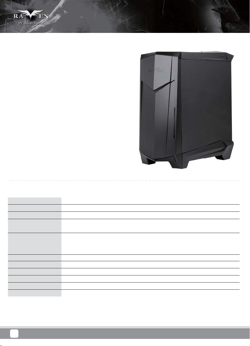
Introduction
The RAVEN RV05, the fifth edition in the exciting RAVEN enthusiasts
chassis series continues the tradition of breaking and evolving the
standards of desktop PC design. With a bold move that sees the
removal of all 5.25” drive bays, the RAVEN team engineers again saw
the opportunity to re-utilize the 90 degree rotated design. Previous
RAVEN models with 90 degree layout often had to compromise on
space efficiency due to fixed length of the motherboard in rotated
orientation. The elimination of 5.25” bays solves this issue naturally
and enables RV05 to be even more balanced in terms of design than
if the same were done to a traditionally-layout case.
With most of the wasted space eliminated from RV05, engineers were
thus able to better optimize the case for the most important
performance-affecting components such as CPU and GPUs.
The result is an expertly-engineered A TX chassis that is just as capable
in terms of compute power and heat dissipation as the first RAVEN
chassis, the RV01, but in half the size. Equipped with latest revision
Air Penetrator AP181 fans that include three speed switches and
modern touches such as externally removable filters and tool-less
panels, the RV05 has everything that PC enthusiasts could wish
for in a compact, high performance computer case that is not only cool
and quiet, but also easy to build and maintain. For those not wanting
to constantly step up in case size to obtain top-level performance,
the RAVEN RV05 is the perfect solution and it may also represent a
glimpse into the future of mainstream enthusiasts PC design.
Specification
Material
Model
Motherboard
Drive Bay
Cooling System
Expansion Slot
Front I/O Port
Power Supply
Expansion Card
Limitation of CPU cooler
Dimension
1
Plastic outer shell, steel body
SST-RV05B (black) / SST-RV05B-W (black + window)
SSI-CEB, ATX, Micro-ATX
Exposed Slim slot-loading optical x 1
Internal 3.5" x 2, 2.5” x 2
Bottom 2 x Air Penetrator 180mm fan 600/900/1200rpm, 17/25/34dBA
Downward compatible with 3 x 120mm fan or 2 x 140mm fan
Top 120mm fan slot x 1
7
USB 3.0 x 2 , audio x 1 , MIC x 1
Optional PS2 (ATX)
Compatible with 12.3” long, width restriction – 6.57”
162mm
242 mm (W) x 529 mm (H) x 498 mm (D)
Page 5
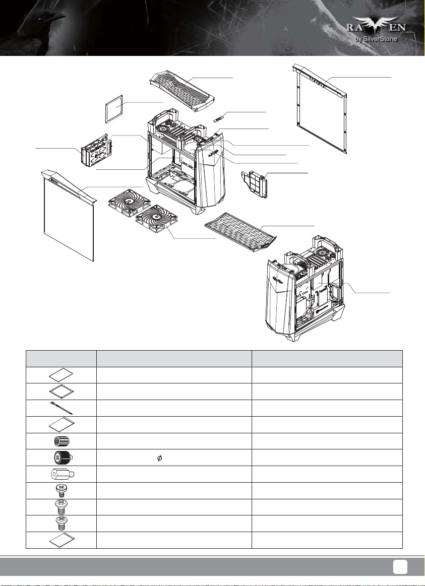
Disassemble Chart
RIGHT-SIDE-PANELTOP COVER
3.5”HDD X2
(OPTION)
PUS FILTER
PSU
(OPTION)
ATX MB (OPTION)
LEFT-SIDE-PANEL
18032 FAN X2
USB COVER
RESET BUTTON
USB 3.0 X2 + MIC + SPK
POWER BUTTON
12025 FAN (OPTION)
SLOT-LOADING OPTICAL DRIVE
(SOLD SEPARATELY)
BOTTOM-FILTER
PICTURE ITEM PURPOSE
MANUAL
FF143-FILTER
BUNCH WIRE TIES
ZIPPER BAG
USER INSTALLATION GUIDE
FAN FILTER FOR REAR 120MM PSU VENT
CABLE MANAGEMENT
CONTAINS SCREWS
2.5”HDD X2
(OPTION)
STANDOFF-SOCKET-WRENCH
SCREW - PAN - 4 X 4.8H - 6 - 32 X 3.4 - NI
STANDOFF-6-32 X6.5H-6-32
SCW-6-32
SCW-M3
SCW-M2
ZIPPER BAG
STANDOFF SCREWS
SECURE 3.5* HDD
MOTHERBOARD STABDOFF
SECURE MOTHERBOARD AND PSU
SECURE 2.5” HDD
SECURE SLIM SLOT-LOADING OPTICAL DRIVE
CONTAINS PARTS
2
Page 6
Disassemble Chart
3
Page 7
Installation Guide
Before you begin, please make sure that you
1
have all components collected
2
check that all components do not have compatibility problems with each other or with the case
3
if possible, assemble the components outside the case first to make sure they are working
keep the motherboard manual ready for reference during installation
4
prepare a Philips screwdriver.
5
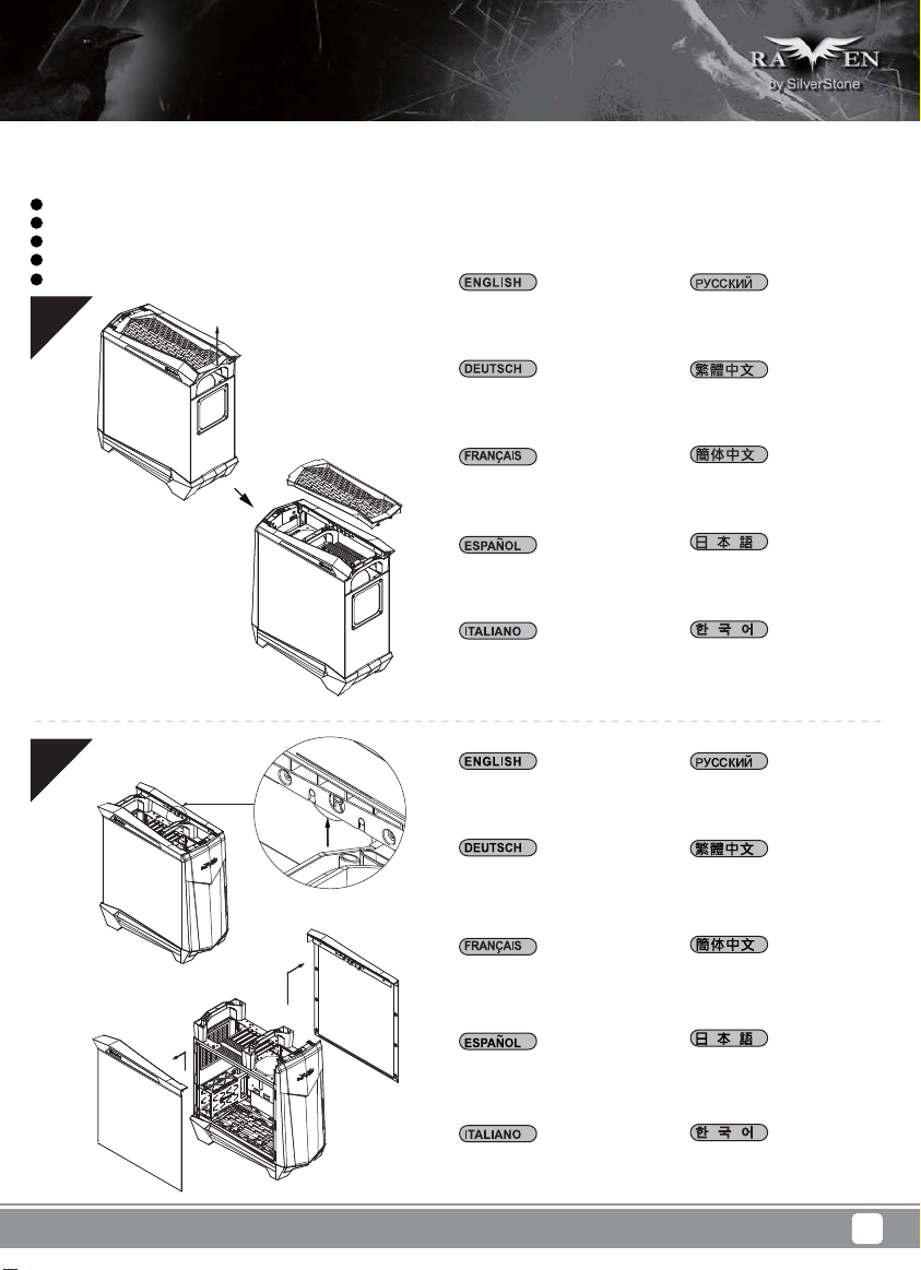
01
Pull top cover off the case
in the direction as illustrated
by the arrow
Снимите верхнюю крышку с
корпуса в направлении,
указанном стрелкой на
иллюстрации.
02
Ziehen Sie die obere Abdeckung
des Gehäuses in die dargestellte
Pfeilrichtung.
Retirez le couvercle supérieur
en le poussant dans le sens
indiqué par la flèche.
Saque la cubierta superior de la
carcasa en la dirección que
indica la flecha
Sollevare il coperchio superiore
del case nella direzione indicata
dalla freccia
Press and hold the hidden
lever, then pull up to remove
side panels
Drücken und halten Sie den
verborgenen Hebel. Ziehen Sie
ihn dann nach oben, um die
Seitenteile zu entfernen.
Appuyez et maintenez enfoncé
le levier caché, puis tirez vers
le haut pour retirer les panneaux
latéraux
請按鍵頭方向用力,
取出上蓋
请按键头方向用力,
取出上盖
図での矢印の方向に引っ張
って、上部カバーをケースか
ら外します。
그림과 같이 화살표 방향으로
케이스에서 상단 커버를 당겨
분리합니다.
Нажав на скрытые
фиксаторы, снимите вверх
боковые панели.
請按壓內部暗釦,
拆除左右兩側板
请按压内部暗扣,
拆除左右两侧板
Presione y aguante la palanca
oculta, luego tire hacia arriba para
retirar los paneles laterales
Tenere premuta la leva nascosta,
quindi sollevare per rimuovere i
pannelli laterali
隠しレバ ーを 押して持ち、引き
上げて側面パネルを外します。
숨겨진 레버를 누른 채로
위로 당겨 측면 패널을
분리합니다.
4
Page 8
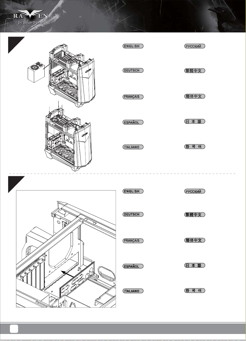
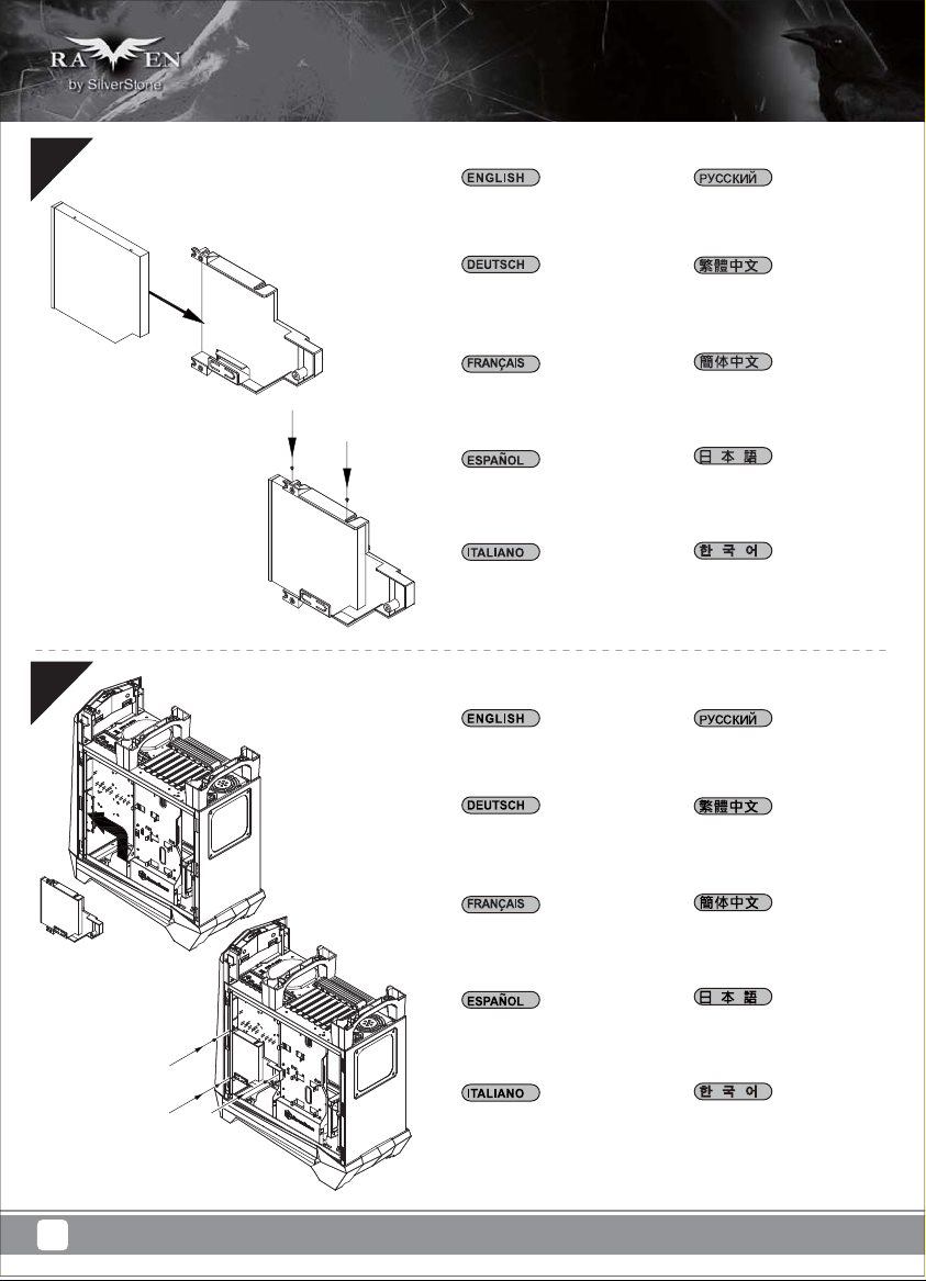
03
Install power supply into the case.
If power supply is longer than
160mm, then remove the 3.5”
drive cage
Установите в корпус блок
питания. Если длина блока
питания превышает 160 мм,
снимите отсек 3,5-дюймового
привода.
04
Bauen Sie das Netzteil ins
Gehäuse ein. Ist das Netzteil
länger als 160 mm, entfernen
Sie den Rahmen für das 3,5”
Laufwerk.
Installez la source d’alimentation
dans le châssis. Si la source
d’alimentation est plus longue
que 160mm, alors retirez la cage
de disque de 3,5"
Instale la fuente de alimentación
en la carcasa. Si la fuente de
alimentación supera una longitud
de 160mm, entonces retire la
carcasa para dispositivos de 3,5”
Installazione dell’alimentatore nel
case. Se l'alimentatore è più lungo
di 160 mm, rimuovere il cage
unità 3.5”
Insert the I/O shield included
with your motherboard
Installieren Sie das hintere
I/O-Blech im Gehäuse.
安裝電源,如果電源長度
超過160mm的話請拆除3.5”
硬碟架
安装电源,如果电源长度
超过160mm的话请拆除3.5”
硬盘架
電源をケースに取り付けます。
電源が160mmより長い場合
は、3.5”ドライブケージを取り
外します。
전원 공급장치를 케이스에
설치합니다. 전원 공급장치가
160mm보다 긴 경우 3.5”
드라이브 케이지를
제거합니다.
Установите в корпус заднюю
панель ввода-вывода
материнской платы.
將I/O彈片裝上機殼
Installez la plaque arrière de
la carte mère dans le boîtier.
Instale la placa trasera de E/S
de la placa base en la carcasa.
Installare la placca I/O della
scheda madre nella sede
preposta.
将I/O弹片装上机壳
ケース内にマザーボード
後部I/Oプレートをインス
トールします。
메인보드 후방 I/O 판을
케이스에 장착합니다.
5
Page 9
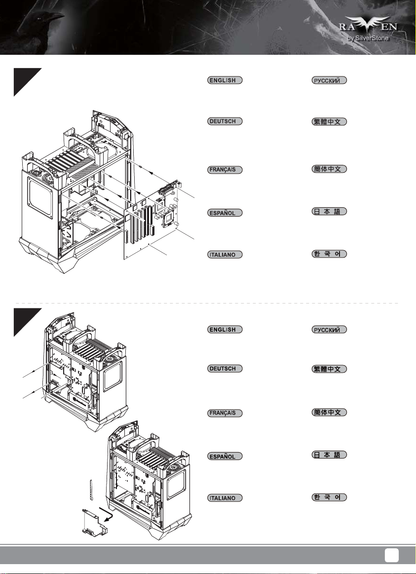
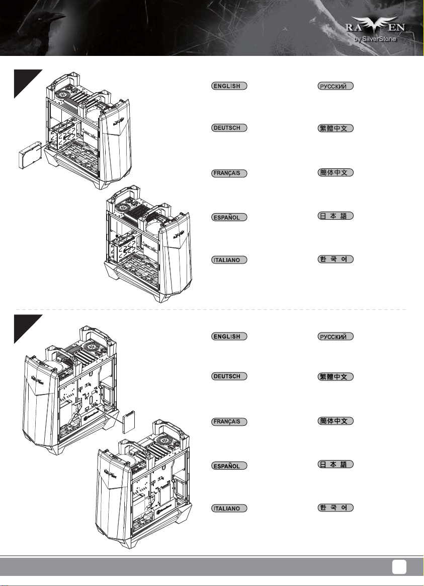
05
Insert standoffs as required
by your motherboard in
corresponding mounting holes,
then install motherboard
При необходимости установите
опорные стойки для системной
платы в соответствующие
крепежные отверстия, затем
установите системную плату.
06
Stecken Sie die Abstandshalter
wie für Ihr Motherboard
erforderlich in die entsprechenden
Befestigungsbohrungen.
Installieren Sie dann das
Motherboard.
Insérez les entretoises comme
requis par votre carte mère dans
les trous de montage
correspondant, puis installez
la carte mère
Inserte los soportes según sea
necesario para su placa base
en los agujeros de montaje
correspondientes, luego instale
la placa base
Inserire nei corrispondenti fori di
fissaggio i distanziatori, come
richiesto dalla scheda madre,
quindi installare la scheda madre
Remove slim optical drive cage
Demontieren Sie dann den
Rahmen für das optische
Laufwerk im Slim-Format.
請依需求安裝主機板螺柱,
安裝主機板
请依需求安装主板螺柱,
安装主板
マザーボードに応じて、必要
な孔にスペーサーを取り付け
てからマザーボードを取り付
けます。
메인보드에서 필요한 경우
해당 장착 구멍에 스탠드오프를
삽입한 후 메인보드를
설치합니다.
Снимите тонкий отсек
оптического привода.
請移除光碟機架
Retirez la cage de lecteur
optique mince
Retire la carcasa para dispositivo
óptico delgado
Rimuovere il cage unità ottica slim
请移除光驱架
スリム光学ドライブケージ
を外します。
슬림형 광 드라이브 케이지를
제거합니다.
6
Page 10
07
Install slim slot-loading optical
drive into the cage
Установите в отсек тонкий
привод оптических дисков с
щелевой загрузкой.
08
Befestigen Sie dann das optische
Laufwerk im Slim-Format in dem
Rahmen.
Installez le lecteur optique mince
à chargement par fente dans la
cage
Instale el dispositivo óptico
delgado de carga mediante
ranura en la carcasa
Installare nel cage l’unità ottica
slim con caricamento a slot
Reinstall optical drive cage
assembly back into the case
Montieren Sie dann den Rahmen
wieder im PC-Gehäuse.
將光碟機安裝上光碟機架
将光驱安装上光驱架
スリムタイプ のスロットローデ
ィング光学ドライブをケージに
取り付け ます。
슬림형 슬롯 로딩 광
드라이브를 케이지에
설치합니다.
Установите на место в корпус
отсек оптического привода.
請將光碟機架裝回機殼
Réinstallez l'ensemble de la cage
de lecteur optique dans le
châssis
Reinstale la carcasa para
dispositivo óptico ya montada
de nuevo en la caja
Reinstallare l’assemblaggio
cage unità ottica nel case
请将光驱架装回机壳
光学ドライブケージアセンブ
リをケースに戻します。
광 드라이브 케이지 어셈블리를
케이스에 도로 설치합니다.
7
Page 11
09
Insert 3.5” drives into the drive
cage, if needed, secure each
drive with a thumb screw
Установите 3,5-дюймовые
приводы в отсек для дисков,
при необходимости закрепите
каждый привод винтом с
накатанной головкой.
10
Schieben Sie die 3,5” Laufwerke
in den Laufwerkrahmen und
sichern Sie jedes Laufwerk mit
einer Rändelschraube.
Insérez un disque de 3,5"
dans la cage de disque si
nécessaire, attachez chaque
disque avec une vis de serrage
Instale los dispositivos de 3,5” en
la carcasa para dispositivos, si es
necesario, asegure cada
dispositivo con un tornillo de
pulgar
Se necessario, inserire le unità
3,5” nel cage unità, fissando
ciascuna unità con una vite ad
alette
Install 2.5” drives behind the
motherboard tray and secure
with screws
Montieren Sie die 2,5” Laufwerke
hinter der Motherboard-Aufnahme
und sichern Sie sie mit Schrauben.
將3.5”硬碟推入硬碟架,
必要的話鎖上一顆手扭螺絲
将3.5”硬盘推入硬盘架,
必要的话锁上一颗手扭螺丝
必要に応じて3.5”ドライブを
ドライブケージに入れ、各ド ラ
イブをサムスクリューで固定し
ます。
필요한 경우 3.5” 드라이브를
드라이브 케이지에 설치하고
납작머리 나사로 각 드라이브를
고정합니다.
За лотком системной платы
установите 2,5-дюймовые
приводы и закрепите их
винтами.
將2.5”硬碟裝上主機板背面,
並鎖上螺絲
Installez des disques de 2,5"
derrière le plateau de la carte
mère et attachez avec des vis
Instale los dispositivos de 2,5”
tras la bandeja de la placa base
y fíjelos con tornillos
Installare le unità 2,5” dietro
il cassetto della scheda madre
e fissarle con viti
将2.5”硬盘装上主板背面,
并锁上螺丝
マザーボードトレイ裏に2.5”
ドライブを取り付け、ネジで
固定します。
메인보드 트래이 뒤에 2.5”
드라이브를 설치하고 나사로
고정합니다.
8
Page 12
11
S
e
ou
e
ls
C
o
C
t
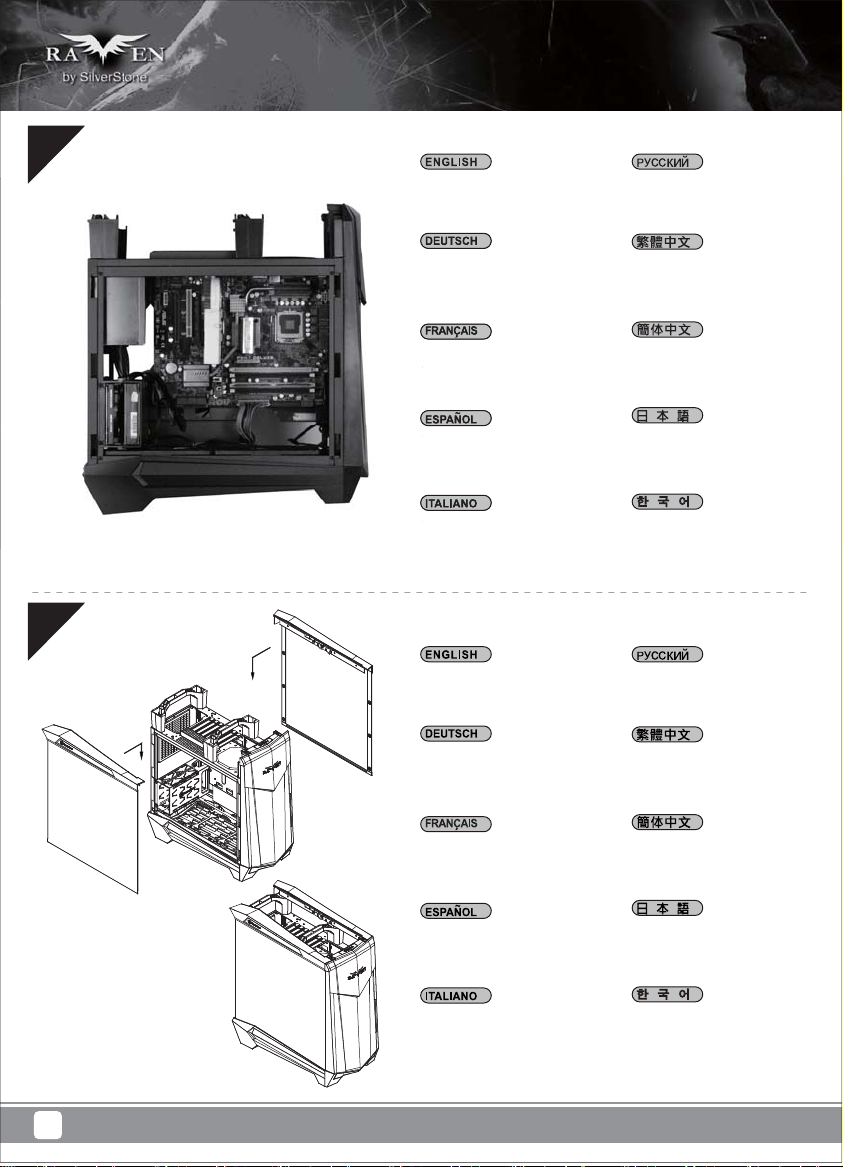
Connect all c
Connect all cables and wires
Schließen Sie alle Kabel an.
chließen Si
Подключите все кабели
и провода.
將連接所有線材
12
Branchez tous les câbles
Branchez t
et les fils
t les fi
Conecte todos los cables
onecte tod
Collegare tutti i cavi ed i fili
ollegare tut
Reinstall side panels back
onto the case
Bringen Sie die Seitenteile
wieder an.
Réinstallez les panneaux
latéraux sur le châssis
Reinstale los paneles laterales
de nuevo en la carcasa
将连接所有线材
ケーブルとリード線を全て
接続します。
모든 케이블과 전선을
연결합니다.
Установите на место
боковые панели корпуса.
裝回左右側板
装回左右侧板
ケースに側面パネルをもどし
ます。
9
Reinstallare sul case i pannelli
laterali
측면 패널을 케이스에 도로
설치합니다.
Page 13
13
Reinstall the top panel to complete installation
Bauen Sie die obere Abdeckung wieder ein.
Die Installation ist damit beendet.
Réinstallez le panneau supérieur pour terminer
l'installation
Reinstale el panel superior para completar
la instalación
Reinstallare il pannello superiore per completare
l'installazione
И, наконец, установите на место верхнюю панель.
裝回上蓋完成組裝
装回上盖完成组装
上面パネルをもどすと、インストールは完了です。
상단 패널을 도로 설치하여 설치를 완료합니다.
10
Page 14
Connector definition
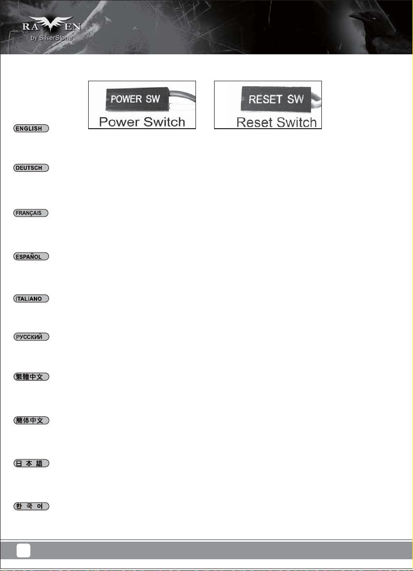
(1) Fort panel connector installation
Power switch and reset switch installation guide:
Please refer to the motherboard manuals for the motherboard’s “Front Panel Connector” or “System Panel Connector” pin definition.
Power switch and reset switch have no polarity, so they can be connected in any orientation.
Ein-/Ausschalter und Rücksetztaste (Reset) installieren:
Bitte suchen Sie in der Motherboard-Dokumentation nach der Pinbelegung der Anschlüsse des Frontbedienfeldes („Front Panel Connectors“
oder „System Panel Connectors“). Ein-/Austaste und Rücksetztaste benötigen keine bestimmte Polarität, können daher beliebig (ohne auf +
und - zu achten) angeschlossen werden.
Guide d'installation des interrupteurs d'allumage et de réinitialisation :
Veuillez-vous référer au manuel de votre carte mère pour la description des broches "des connecteurs du panneau frontal" et des broches "des
connecteurs du panneau système". Les interrupteurs d'allumage et de réinitialisation ne possède pas de polarité, donc ils peuvent être branché
dans les deux sens.
Guía de instalación de los interruptores de encendido y reseteo:
Por favor, consulte en los manuales de la placa base la configuración de pines del “Conector de panel frontal” ó “Conector de panel de sistema”
de su placa base. Los interruptores de encendido y reseteo no tienen polaridad, luego se pueden conectar con cualquier orientación.
Guida all’installazione dei connettori Power Switch e Reset Switch:
Fare riferimento al manuale della scheda madre nella sezione “Connettori del pannello frontale” o “Connettori del pannello di sistema”.
Power switch e reset switch non hanno polarità, posso essere pertanto connessi con qualsiasi orientamento.
Инструкция по подключению выключателя питания и кнопки перезагрузки (reset):
Описание контактов разъемов приведены в разделах “Разъем ы передней панели” или “Разъем ы системной панели” руководства
пользователя материнской платы. Выключатель питания и кнопка перезагрузки не имеют полярности, поэтому их можно подключать
любой ориентации.
в
Power Switch 與Reset Switch安裝說明:
請參考主機說明書的Front Panel Connectors安裝Pin Define,將Connector插上;Power Switch 與Reset Switch並無正負極性之分,
反插正插都不影響功能性。
Power Switch 与Reset Switch安装说明:
请参考主机说明书的Front Panel Connectors 安装Pin Define,将Connector插上;Power Switch与Reset Switch并无正负极性之分,
反插正插都不影响功能性。
電源スイッチおよびリセットスイッチのインストールガイド:
マザーボードの「フロントパネルコネクタ」または「システムパネルコネクタ」のピン配列についてはマザーボードマニュアルを参照
してください。電源スイッチとリセットスイッチに極性はないので、いずれの方向でも接続できま。
파워 스위치 및 리셋 스위치 설치 가이드
메인보드 매뉴얼의 전면패널 커넥터 혹은 시스템패널 커넥터 핀을 참조하기 바랍니다. 파워 스위치와 리셋 스위치는 극성이 없어
어떤 방향으로 설치해도 무방합니다.
11
Page 15

LED connector installation guide:
Please refer to the motherboard manuals for the motherboard’s “Front Panel Connector” or “System Panel Connector” pin definition. White colored
wires are negative while other colored wires are positive. Power LED connector is made to be individual pins by design to accommodate different
motherboard specifications.
Bitte suchen Sie in der Motherboard-Dokumentation nach der Pinbelegung der Anschlüsse des Frontbedienfeldes („Front Panel Connectors“ oder „
System Panel Connectors“). Die weißen/ schwarz Adern sind negativ (-), die farbigen Adern positiv (+).Die Kabel für die Betriebsanzeige-LED sind
zur Kompatibilität mit unterschiedlichsten Motherboards einzeln, nicht als kompletter Stecker ausgeführt. Achten Sie hier bitte auf die richtige Polarität,
lesen Sie in der Dokumentation Ihres Motherboards nach.
Veuillez-vous référer au manuel de votre carte mère pour la description des broches "des connecteurs du panneau frontal" et des broches "des
connecteurs du panneau système". Les câbles colorés en blanc/noir sont négatifs alors que ceux d'une autre couleur sont positifs. Les câbles de
la LED Power sont séparés afin d'être compatible avec différentes cartes mères, donc vérifiez bien qu'ils sont branchés avec la bonne polarité en
vous référant au manuel de votre carte mère
Por favor, consulte en los manuales de la placa base la configuración de pines del “Conector de panel frontal” ó “Conector de panel de sistema”
de su placa base. Los cables de color blanco/negro son negativos mientras que los de color son positivos. Los cables LED de potencia tienen
pines separados para compatibilidad con diferentes definiciones de pines de la placa base luego por favor, asegúrese de que están conectados
en la polaridad correcta consultando el manual de su placa base.
Fare riferimento al manuale della scheda madre nella sezione “Connettori del pannello frontale” o “Connettori del pannello di sistema”. I cavi di
colore bianco/nero sono il polo negativo, mentre quelli di colore diverso il positivo.
Описание контактов разъемов приведены в разделах “Разъемы передней панели” или “Разъемы системной панели” руководства
пользователя материнской платы. Белые/черный провода - отрицательной полярности, цветные провода - положительной полярности.
Провода светодиодного индикатора питания имеют отдельные контакты для совместимости
плат, поэтому обратитесь к руководству пользователя материнской платы и убедитесь, что полярность соблюдена.
請參考主機說明書的Front Panel Connectors安裝Pin Define,將Connector插上; 白/黑色線的部分為負極,彩色線的部分是正極。Power LED為了適
應各主機板的不同, 特別設計為散Pin樣式,請安心使用。
:
с различными типами контактов материнских
请参考说明书的Front Panel Connectors安装Pin Define,将Connector插上;白/黑色线的部份为负极,彩色线的部份为正极。Power LED为了适应主机
板的不同, 特别设计为散Pin样式,请安心使用。
マザーボードの「フロントパネルコネクタ」または「システムパネルコネクタ」ピン配列についてはマザーボードマニュアルを参照してください。
白/黑色のリード線はマイナスで、色の着いたリード線がプラスです。電源LEDリード線は種々のマザーボードピン定義と互換性を持たせるため分離
されたピンとなっているので、ご使用のマザーボードマニュアルを参照して、適切な極性に接続されるようお確かめください。
메인보드 매뉴얼의 전면패널 커넥터 혹은 시스템패널 커넥터 핀을 참조하기 바랍니다. 하얀/검은선의 경우 음극이며, 다른 색의 경우
양극입니다. 파워 LED 선은 분리되어 다양한 메인보드에서 동작할 수 있도록 되어 있습니다. 그러므로 메인보드 매뉴얼을 참조하여 올바를
극성을 주의해 선택하시기 바랍니다.
12
Page 16

(2) Front I/O connector guide
Below are the front I/O connectors pin definition, please also check your motherboard manual to cross reference with motherboard’s
front I/O pin headers. SilverStone’s I/O connectors are in block type to simplify installation.
Nachstehend finden Sie die Pinbelegung der vorderen E/A-Anschlüsse; bitte gleichen Sie zudem das Handbuch Ihres Motherboards mit
den vorderen E/A-Pinzuweisungen ab. SilverStones E/A-Anschlüsse befinden sich zur Vereinfachung der Installation in Blockart.
Au dessous de la description des broches des ports d'E/S, veuillez aussi vérifier sur le manuel de votre carte mère de manière croisée
que les broches sont correctement placées. Les connecteurs d'E/S de SilverStone sont en bloc pour en simplifier leur installation.
A continuación se detallan los pines para conectores E/S frontales, compruebe también por favor el manual de su placa base para
cotejar los pines E/S frontales de la misma. Los conectores E/S de SilverStone son del tipo bloque para simplificar la instalación.
Di seguito lo schema delle connessioni I/O frontali, confrontare lo schema con quanto riportato sul manuale della scheda madre per
effettuare un controllo incrociato. I connettori I/O Silverstone, per semplificare l’installazione, sono del tipo “a blocco”.
Ниже приведено описание контактов передних разъемов ввода/вывода. Обратитесь также к руководству пользователя материнской
платы за описанием передних разъемов ввода/вывода типа "пин-хедер". Разъемы ввода/вывода "SilverStone" - блочного типа, что
облегчает сборку.
下表為Front I/O Connectors的Pin Define,請參閱主機板說明書的各Front I/O Connectors Pin Define一一核對。
ML07的Front I/O Connectors完全採用集合
下表为Front I/O Connectors的Pin Define,请参阅主机板说明书的各Front I/O Connectors Pin Define一一核对。
ML07的Front I/O Connectors完全采用集合Pin方式以简化安装。
以下はフロントI/Oコネクタピン配列ですが、お持ちのマザーボードのフロントI/Oピンヘッダは、マザーボードマニュアルをご参照
ください。シルバーストーンのI/Oコネクタは、インストールの容易なブロックタイプになっています。
아래는 전면 I/O 커넥터의 핀 사양입니다. 메인보드 매뉴얼을 참조해, 메인보드의 전면 I/O 핀사양을 재 확인한 후 설치합니다.
SilverStone의 I/O 커넥터는 블록 타입으로 구성되어 있어 간편한 설치가 가능합니다.
Pin方式以簡化安裝。
13
Page 17

Component size limitations
The RAVEN RV05 was designed to accommodate oversized components, but we still recommend referring
to the following dimension guidelines
(1) CPU Cooler limitation
162mm
9mm 13mm
Height limitation for CPU cooler is 162mm with 13mm clearance over the motherboard’s top edge.
Höhenbeschränkung für CPU-Kühler 162 mm mit einem Freiraum von 13 mm oberhalb der Motherboard-Oberkante.
La limitation de hauteur des refroidisseurs de processeurs est 162mm avec un espace de 13mm au-dessus du bord supérieur de la carte mère.
La limitación de altura para disipadores de CPU es de 162mm con un espacio libre de 13mm sobre el borde superior de la placa base.
La limitazione dell’altezza del dissipatore di calore CPU è di 162 millimetri con uno spazio libero di 13 mm sopra il bordo superiore della scheda madre.
Ограничение по высоте для системы охлаждения процессора составляет 162 мм с 13-мм зазором над верхним краем системной платы.
Cooler限高是162mm,Cooler外源允許超出主機板上邊界13mm
Cooler限高是162mm,Cooler外源允许超出主板上边界13mm
CPUクーラーの高さ限度は、マザーボード上側の余裕13mmを取って、162mmです。
CPU 쿨러의 높이 제한은 162mm로서 메인보드 상단 가장자리 위로의 허용 오차가 13mm입니다.
14
Page 18

(2) Power supply limitation
160mm
343.8mm
A: Length limitation
If no 3.5” drives are installed, there is no limitation on power supply size with the drive cage removed
If the 3.5” drive cage is in use, the recommended depth of the power supply is 160mm
B: Power supply cable length recommendation
Below is the recommended cable length for retail ATX motherboards. If the cables are not long enough, please purchase extension cables.
A: Längenbeschränkung
Werden keine 3,5” Laufwerke installiert und wird der Laufwerkrahmen entfernt, unterliegt das Netzteil keiner Größenbeschränkung.
Wir der 3,5” Laufwerkrahmen verwendet, liegt die empfohlene Tiefe des Netzteils beim 160 mm.
B: Längenempfehlung Netzteilkabel
Nachfolgend finden Sie die empfohlenen Kabellängen für handelsübliche ATX-Motherboards. Sind die Kabel zu kurz, kaufen Sie
Verlängerungskabel.
A : Limitation de longueur
Si aucun disque de 3,5" n'a été installé, il n'y a aucune limitation pour la taille de la source d'alimentation lorsque la cage de disque a été retiré
Si la cage de disque de 3,5" est utilisée, la profondeur recommandée pour la source d'alimentation est 160mm
B : Recommandations pour la longueur du câble de la source d’alimentation
Ci-dessous est la longueur de câble recommandée pour les cartes mères ATX. Si les câbles ne sont pas assez long, veuillez acheter des
rallonges.
A: Limitación de altura
Si no se instalan dispositivos de 3,5”, no existirá limitación en el tamaño de la fuente de alimentación con la carcasa para dispositivos retirada
Si se usa la carcasa para dispositivos de 3,5”, la profundidad recomendada de la fuente de alimentación será de 160mm
B: Recomendación de la longitud del cable de la fuente de alimentación
A continuación se encuentra la longitud de cable recomendada para placas base ATX. Si los cables no son lo bastante largos, por favor compre cables de extensión.
A: Limitazione della lunghezza
Se non sono installate unità 3,5”, quando è rimosso il cage unità, non c’è alcuna limitazione per le dimensioni dell’alimentatore
Se il cage unità 3,5” è in uso, la profondità raccomandata per l'alimentatore è di 160 mm
B: Raccomandazioni sulla lunghezza del cavo d’alimentazione
Di seguito sono elencate le lunghezze raccomandate dei cavi d’alimentazione per le schede madre ATX vendute al dettaglio. Acquistare delle
prolunghe qualora i cavi non fossero sufficientemente lunghi.
A: Ограничение по длине
Если 3,5-дюймовые приводы не устанавливаются, ограничений на размер блока питания при снятом отсеке для приводов нет
Если отсек 3,5-дюймовых приводов используется, рекомендуемая глубина блока питания составляет 160 мм
B: Рекомендации по длине кабелей блока питания
Ниже приведены рекомендации по длине кабелей для самостоятельно приобретаемых системных плат ATX. Если длина кабелей
недостаточна, приобретите удлинительные кабели.
A:長度限制
如果下方沒有安裝3.5”硬碟,電源就幾乎沒有長度限制,您可以使用任何超大瓦數的電源
如果電源前方有安裝3.5” 硬碟,我們建議您使用160mm以內的電源
B:電源線材建議長度:
以下是以一般市售ATX主機板抓出來的各線材建議長度列表,請先確認電源線長度是否足夠
如果不夠請選購所需要的延長線
15
Page 19

A:长度限制
如果下方没有安装3.5”硬盘,电源就几乎没有长度限制,您可以使用任何超大瓦数的电源
如果电源前方有安装3.5” 硬盘,我们建议您使用160mm以内的电源
B:电源线材建议长度:
以下是以一般市售ATX主板抓出来的各线材建议长度列表,请先确认电源线长度是否足够
如果不够请选购所需要的延长线
A: 長さ制限
3.5”ドライブが装着されていない場合、ドライブケージなしでは電源のサイズに制限はありません。
3.5”ドライブケージが使用される場合、推奨される電源奥行きは160mmです。
B: 電源ケーブル推奨長さ
下図はリテールATXマザーボード用のケーブル推奨長さです。ケーブル長が不十分の場合は、延長ケーブルをご購入ください。
A: 길이 제한
3.5” 드라이브가 설치되지 않은 경우 드라이브 케이지를 제거한 상태에서 전원 공급장치 크기에 대한 제한이 없습니다.
3.5” 드라이브 케이지를 사용 중인 경우 전원 공급장치의 권장 깊이는 160mm입니다.
B: 권장 전원 공급장치 케이블 길이
다음은 소매 ATX 메인보드용 권장 케이블 길이입니다. 케이블이 충분히 길지 않을 경웅 연장 케이블을 구매하십시오.
Cable type and location
EPS 8pin/ATX4pin (from left side of PSU)
ATX 24Pin (from left side of PSU)
SATA 15Pin (from left side of PSU to 3.5” drive)
SATA 15Pin (from left side of PSU to 2.5” drive)
SATA 15Pin (from left side of PSU to slim optical drive)
PCIE 8/6pin (to first expansion slot)
Minimum length
550mm
300mm
100mm
300mm
350mm
450mm
mm320.241Distance
mm320.241Distance
When using a non-modular PSU with a depth of 140mm, route the CPU 8/4 Pin through the indicated hole first.
PP07 extension cables can be used if the cable is not long enough.
Bei Einsatz eines nicht-modularen Netzteils mit einer Tiefe von 140 mm führen Sie zunächst den CPU-Anschluss 8/4 durch die angezeigte Bohrung.
Ist das Kabel zu kurz, können Sie ein PP07-Verlängerungskabel verwenden.
Quand vous utilisez un PSU non-modulaire d'une profondeur de 140 mm, placez d'abord la broche 8/4 du CPU à travers le trou indiqué.
Des câbles d'extension PP07 peuvent être utilisés si le câble n'est pas assez long.
16
Page 20

Cuando se usa una FA no modular con una profundidad de 140mm, primero enrute los 8/4 pines de la CPU a través del agujero indicado.
Los cables de extensión PP07 se pueden usar si el cable no es lo bastante largo.
Quando si usa una PSU non modulare con una profondità di 140 mm, prima infilare nel foro indicato i pin 8/4 della CPU.
Se il cavo non è sufficientemente lungo, possono essere usati cavi di prolunga PP07.
При использовании немодульного блока питания с глубиной 140 мм сначала пропустите разъем процессора 8/4 через показанное отверстие.
Если длина кабеля окажется недостаточной, в корпусе PP07 можно использовать удлинительные кабели.
如果是使用低階非模組化的電源,電源深度為140mm CPU 8/4 Pin請優先由主機板前方穿過
走最短距離,如果不幸長度還是不足,你可以購買PP07延長線
如果是使用低阶非模块化的电源,电源深度为140mm CPU 8/4 Pin请优先由主板前方穿过
走最短距离,如果不幸长度还是不足,你可以购买PP07延长线
奥行き140mmの非モジュール式PSUを使用する場合、CPU 8/4ピンを表示された孔に通してください。
ケーブル長が不足している場合は、PP07延長ケーブルが利用できます。
깊이가 140mm인 비모듈식 PSU를 사용하는 경우, 먼저 CPU 8/4 핀을 표시된 구멍을 통과시키십시오.
케이블의 길이가 충분히 길지 않을 경우 확장 케이블 PP07을 사용할 수 있습니다.
(3) Graphics card / expansion card length limitation
314.2mm
RV05 can support 12.3” (314.2mm) long cards, which covers all retail consumer graphics cards available on the market.
RV05 unterstützt Karten bis 12,3” (314.2mm). Dies deckt alle auf dem Markt verfügbare Consumer-Grafikkarten ab.
17
Page 21

RV05 peut supporter des cartes de jusqu'à 12,3" (314.2 mm) de long, ce qui couvre toutes les cartes graphiques disponibles actuellement sur le marché.
La RV05 puede aceptar tarjetas largas de 12,3” (314.2mm), lo que cubre todas las tarjetas gráficas para usuario disponibles en el mercado.
RV05 supporta schede lunghe da 12,3” (314.2 mm), coprendo tutte le schede grafiche consumer in vendita al dettaglio disponibili sul mercato.
Корпус RV05 позволяет устанавливать 12,3-дюймовые (314.2 мм) карты, что покрывает весь доступный рынок розничной продажи графических карт.
RV05支援到PCIE規格定義的上限12.3”顯示卡,市面上零售的消費及顯示卡應該都能安裝
RV05支持到PCIE规格定义的上限12.3”显示适配器,市面上零售的消费及显示适配器应该都能安装
RV05は12.3” (314.2mm)長のカードに対応します。これは市場に出回るリテール消費用グラフィックスカード全てを網羅します。
RV05는 12.3”(314.2mm)의 긴 카드를 지원할 수 있으며, 이는 시중에 출시된 모든 소매 소비자용 그래픽 카드를 포함합니다.
(4) Optical drive limitation
84.8mm
4mm
14.9mm
8.7mm
12.7mm
144.3mm
25.4mm
82.8mm
3mm
82.8mm
16mm
128mm
31.2mm
RV05 support only slim slot-loading optical drives with thickness of 12.7mm or 9.5mm
16mm
2.9mm
102.6mm
82.8mm
128mm
122.5mm
11.3mm
2.5mm
3mm
1mm
9.7mm
36.71mm
129mm
10.1mm
16mm82.8mm
25.4mm
2.3mm
RV05 unterstützt ausschließlich optische Laufwerke im Slim-Format mit einer Dicke von 12,7mm oder 9,5mm
RV05 supporte seulement les lecteurs optiques minces à chargement par fente avec une épaisseur de 12,7 mm ou 9,5 mm
La RV05 acepta solo dispositivos ópticos delgados de carga mediante ranura con una profundidad de 12,7mm o 9,5mm
RV05 supporta solo unità ottiche slim con caricamento a slot di spessore di 12,7 mm o 9,5 mm
RV05 допускает установку только тонких оптических приводов с щелевой загрузкой дисков толщиной 12,7 мм или 9,5 мм
RV05僅支援薄型吸入式光碟機,12.7mm或是9.5mm厚度
RV05仅支持薄型吸入式光驱,12.7mm或是9.5mm厚度
RV05は、厚さ12.7mmまたは9.5mmのスリムタイプのスロットローディング光学ドライブにのみ対応します。
RV05는 두께가 12.7mm 또는 9.5mm인 슬림형 슬롯 로딩 광 드라이브를 지원합니다.
18
Page 22

(5) Motherboard size limitation
AB
A. Illustration: ASUS Rampage III Extreme for example is wider than standard ATX motherboards
Although RV05 was not designed for reference Extended-ATX motherboard, the internal space can still allow installation for motherboards with width
of up to 11 inches. In addition, the motherboard tray has mounting standoffs for supporting SSI-CEB dual CPU motherboards. Enthusiast motherboards
such as ASUS’s Rampage III Extreme and EVGA’s X58 Classified 4-Way SLI are 10.6 and 10.375 inches wide respectively. These are wider than
standard ATX motherboard specification of 9.6 inches, but will fit inside RV05 without any problems.
B. Illustration: New generation of SSI-CEB server or workstation motherboards no longer require CPU cooler mounting holes on the motherboard tray. Coolers
can now be installed directly on the motherboard. As a result, we eliminated support for SSI-CEB CPU cooler mounting holes and instead increased
the large gap on the motherboard tray to support CPU cooler back plates swapping with modern LGA 1156/1155/1150 motherboards. The RV05
chassis’ support for new and future SSI-CEB motherboards should be unaffected by this change.
A. Abbildung: Die ASUS Rampage II Extreme beispielsweise ist breiter als ein Standard-ATX-Motherboards.
Obwohl das RV05 keine echten Extended ATX- (SSI-EEB) Motherboards unterstützt, unterstützt es ATX-Modelle mit einer Breite bis 11-Zoll. Löcher
für Motherboard-Abstandhalter sind zur Unterstützung von SSI-CEB verfügbar, sodass High-End-Enthusiasten ATX-Platinen, wie ASUS Rampage III
Extreme oder EVGA X58 SLI Classified, die bis zu 10,6-Zoll breit sind, komfortabel im RV05 unterbringen können.
B. Abbildung: Hochmoderne Motherboards von SSI-CEB-Servern und -Arbeitsrechnern benötigen keine Löcher zur CPU-Kühlermontage am
Motherboard-Einschub mehr.
Die Kühler können nun direkt am Motherboard installiert werden. Dadurch haben wir die Unterstützung der Löcher zur SSI-CEB-CPU-Kühlermontage
aufgegeben und stattdessen den Abstand am Motherboard-Einschub vergrößert; dadurch werden CPU-Kühlerrückplatten unterstützt, die mit einer
größeren Anzahl an LGA 115X-Motherboards kompatibel sind. Die Unterstützung neuer und zukünftiger SSI-CEB-Motherboards durch das
RV05-Gehäuse wird durch diese Änderung nicht beeinflusst.
A. Illustration : ASUS Rampage III Extreme par exemple est plus large que les cartes mères standard ATX
Bien que le RV05 ne supporte pas les cartes mères Extended ATX (SSI-EEB), il supporte les modèles ATX jusqu'à 11 pouces de large. Des trous
pour les espaceurs de carte mère sont inclus pour supporter SSI-CEB pour que les cartes ATX de haut de gamme tels que ASUS Rampage III
Extreme ou EVGA X58 SLI Classified, qui ont une largeur de jusqu'à 10,6", puissent rentrer facilement à l'intérieur du RV05.
B. Illustration : Les portes-carte mère destinés à la nouvelle génération de cartes mères pour station de travail ou serveur SSI-CEB n'ont plus besoin
de trous de montage pour le refroidisseur de l'unité centrale.
Les refroidisseurs peuvent désormais s'installer directement sur la carte mère. Nous avons ainsi éliminé le support destiné aux trous de montage
pour le refroidisseur de l'unité centrale SSI-CEB et l'espace sur le porte-carte mère permettant de permuter les plaques arrière du refroidisseur,
avec plus de cartes mères LGA 115X, est agrandi. Le support du châssis RV05 pour les nouvelles cartes mères SSI-CEB et celles à venir, ne sera
pas affecté par cette modification.
19
Page 23

A. Ilustración: la ASUS Rampage III Extreme, por ejemplo, es más ancha que las placas base ATX estándar
Aunque la RV05 no acepta verdaderas placas base ATX Extendidas (SSI-EEB), acepta modelos ATX de hasta 11 pulgadas de ancho. Los agujeros
para soportes de la placa base se incluyen para aceptar SSI-CEB, luego los entusiastas de placas ATX de alto rendimiento como la A SUS Rampage III
Extreme o la EVGA X58 SLI Classified, que tienen hasta 10,6 pulgadas de ancho, puedan encajar cómodamente dentro de la RV05
B. Ilustración: La nueva generación de placas base de servidor o estaciones de trabajo SSI-CEB ya no necesita agujeros de montaje para disipador
de CPU en la bandeja de la placa base.
Los disipadores ahora se pueden instalar directamente en la placa base. Como resultado, eliminamos los agujeros de montaje de disipador para
CPU SSI-CEB y en cambio aumentamos el gran espacio en la bandeja de la placa base para aceptar el cambio de placas traseras para disipador
de CPU con más placas base LGA 115X. Que el chasis de la RV05 acepte placas base SSI-CEB nuevas y futuras no debería verse afectado por
este cambio.
A. Illustrazione: ASUS Rampage III Extreme, ad esempio, è più larga delle schede madre ATX standard
Anche se RV05 non supporta schede madre true Extended ATX (SSI-EEB), supporta modelli ATX larghi fino a 11 pollici. Sono inclusi fori per
distanziatori della scheda madre per supportare SSI-CEB così che schede ATX high-end per appassionati come ASUS Rampage III Extreme o
EVGA X58 SLI Classified, che sono larghe fino a 10.6 pollici, possono stare comodamente dentro a RV05.
B. Illustrazione: Nuove generazioni di schede madre per server SSI-CEB o per workstation non richiedono più fori di montaggio per dispersori di
calore CPU sul cassetto della scheda madre.
I dispersori di calore possono essere installati direttamente sulla scheda madre. Di conseguenza abbiamo eliminato il supporto per fori di montaggio
per il dispersore di calore SSI-CEB, ed invece abbiamo aumentato l’ampio spazio libero sul cassetto della scheda madre per supportare scambiatori
di calore CPU con più schede madri LGA 115X. Il supporto del telaio di RV05 per le nuove e future schede madre SSI-CEB non dovrebbe essere
influenzato da questo cambiamento.
A. Иллюстрация: Например, системная плата ASUS Rampage III Extreme шире стандартных системных плат ATX
Хотя RV05 не поддерживает оригинальные системные платы Extended ATX (SSI-EEB), он поддерживает модели ATX шириной до 11 дюймов.
Отверстия под опорные винты системной платы предназначены для поддержки SSI-CEB, благодаря чему поклонники плат ATX, таких как
ASUS Rampage III Extreme или EVGA X58 SLI Classified шириной до 10,6 дюйма, могут легко разместить их в корпусе RV05.
B. Иллюстрация: При установке системных плат нового поколения серверов или рабочих станций SSI-CEB больше не требуются монтажные
отверстия для установки системы охлаждения процессора на лотке системной платы.
Системы охлаждения теперь можно устанавливать непосредственно на системной плате. В результате монтажные отверстия для установки
системы охлаждения процессора SSI-CEB не используются, а вместо них увеличен размер отверстия на лотке системной платы для поддержки
задних пластин систем охлаждения процессора, обеспечивающих замену на системные платы LGA 115X. Корпус RV05 поддерживает установку
новых и перспективных системных плат SSI-CEB, несмотря на эти изменения.
A. 圖:ASUS Rampage III Extreme較一般主機板寬度為寬
RV05雖然尚未支援到E-ATX主機板,但是內部的空間允許最大寬度到11”的主機板。因此我們的主機板螺柱設計到支援SSI-CEB規格的雙CPU主機板。
而一般玩家級ATX主機板也有像ASUS Rampage III Extreme或EVGA X58 SLI Classified深度達到10.6”,超過正常9.6”的尺寸。一般ATX機殼是不一
定能安裝的。而RV05是可以正常支援沒問題的。
B. 圖: 新一代SSI-CEB規格伺服器主機板,已經沒有利用SSI規範的Xeon Cooler在機殼上的鎖固孔位。
而Cooler本身是所在主機板上。我們新一代的機殼為了配合LGA1155的位置,而把MB底板對應的開孔加大,因而取消了SSI規範上的Cooler鎖固螺柱。
並不是不相容於SSI CEB主機板;只是因應主機板規格的演進而修改設計。
A. 图:ASUS Rampage III Extreme较一般主板宽度为宽
RV05虽然尚未支持到E-ATX主板,但是内部的空间允许最大宽度到11”的主板。因此我们的主板螺柱设计到支持SSI-CEB规格的双CPU主板。而一般玩家
级ATX主板也有像ASUS Rampage III Extreme或EVGA X58 SLI Classified深度达到10.6”,超过正常9.6”的尺寸。一般ATX机壳是不一定能安装的。
而RV05是可以正常支持没问题的。
B. 图: 新一代SSI-CEB规格服务器主板,已经没有利用SSI规范的Xeon Cooler在机壳上的锁固孔位。
而Cooler本身是所在主板上。我们新一代的机壳为了配合LGA1155的位置,而把MB底板对应的开孔加大,因而取消了SSI规范上的Cooler锁固螺柱。
并不是不相容于SSI CEB主板;只是因应主板规格的演进而修改设计。
A. 図:例として、ASUS Rampage III Extremeは標準のATXマザーボードより幅が広いです。
RV05は純正Extended ATX(SSI-EEB)マザーボードに対応しないものの、それは最高11インチ幅のATXモデルに対応します。SSI-CEBに対応すべく
マザーボードスペーサー用穴が開いているので、ASUS Rampage III ExtremeまたはEVGA X58 SLI Classifiedといった最大10.6インチ幅のハイエン
ドユーザー対象ATXボードもRV05に正しく収めることができます。
B. 図:新世代SSI-CEBサーバーまたはワークステーション・マザーボードは、マザーボードトレイ上でCPUクーラー取り付け穴をもはや必要としま
せん。クーラーは、マザーボード上に直接設置できます。その結果、当社はSSI-CEB CPUクーラー取り付け穴への対応をやめ、その代わりに、よ
り多くのLGA 115XマザーボードでCPUクーラー・バックプレート・スワッピングに対応するよう、マザーボードトレイ上の間隙を増やしました。
RV05ケースの新しい、将来のSSI-CEBマザーボードへの対応は、この変化に影響を受けることはありません
A. 그림: 예를 들어 ASUS Rampage III Extreme은 폭이 표준 ATX 메인보드보다 넓습니다.
RV05가 트루 확장 ATX(SSI-EEB) 메인보드를 지원하지 않더라도 폭이 최대 11인치인 ATX 모델은 지원합니다. 메인보드 스탠드 오프 구멍이
있어 SSI-CEB를 지지하기 때문에 최대 폭이 10.6 인치인 ASUS Rampage III Extreme 또는 EVGA X58 SLI Classified와 같은 매니어용 고급
ATX 메인보드를 RV05에 무리없이 들어앉힐 수 있습니다.
B. 그림: 차세대 SSI-CEB 서버 또는 워크스테이션 메인보드의 경우 메인보드 트레이에 더 이상 CPU 쿨러 장착 구멍이 필요하지 않습니다.
이제 쿨러를 메인보드에 직접 설치할 수 있습니다. 그 결과 SSI-CEB CPU 쿨러 장착 구멍을 없앴으며 그 대신 메인보드 트레이 상의 간극을
넓혀 CPU 쿨러 백 플레이트에서 더 많은 LGA 115X 메인보드와 스와핑을 지원합니다. 향후 새로운 SSI-CEB 메인보드에 대한 RV05 섀시의
지원은 이러한 변경에도 영향을 받지 않아야 합니다.
20
Page 24

(6) Liquid cooling radiator limitations
2.2mm
33mm
34.6mm
19.8mm18.8mm
13.1mm 3.6mm
37.5mm
AB
22.8mm
101mm
32.1mm
27.8mm
C
The bottom panel of RV05 supports fan mountings of radiator with sizes of 180mm x 2, 140mm x 2, or 120mm x 3.
Since radiators have different designs with how much they protrude from the frame of fans, we recommend double check their dimensions
with the following guide:
A: Area surrounding top 120mm fan
B: Area surrounding the bottom if mounted with three 120mm fans
C: Area surrounding the bottom if mounted with two 140mm fans
D: Area surrounding the bottom if mounted with two 180mm fans
3mm
7.5mm
D
31.8mm
32.8mm
Die Bodenplatte des RV05 unterstützt die Befestigung von Kühlern in den Größen 180 mm 2x, 140 mm 2x oder 120 mm 3x.
Da Radiatoren unterschiedlich aufgebaut sind und unterschiedlich weit vom Rahmen des Lüfters herausragen, empfehlen wir ihre Maße anhand
der folgenden Hinweise zu prüfen:
A: Bereich um den oberen 120 mm Lüfter
B: Bereich am Boden, wenn drei 120 mm Lüfter installiert sind
C. Bereich am Boden, wenn zwei 140 mm Lüfter installiert sind
D: Bereich am Boden, wenn zwei 180 mm Lüfter installiert sind
Le panneau inférieure du RV05 supporte le montage de ventilateurs de radiateur avec des tailles de 180mm x 140mm x 2, 2, ou 120mm x 3.
Puisque les radiateurs ont des designs différents tels que comment ils dépassent du cadre des ventilateurs, nous vous recommandons de vérifier
à nouveau leurs dimensions avec le guide suivant :
A : Zone autour du ventilateur supérieur de 120mm
B : Zone autour du bas si trois ventilateurs de 120 mm sont installés
C : Zone autour du bas si deux ventilateurs de 140 mm sont installés
D : Zone autour du bas si deux ventilateurs de 180mm sont installés
21
Page 25

El panel inferior de la RV05 acepta montar ventiladores de radiador con tamaños de 180mm x 2, o 120mm x 3
Ya que los radiadores tienen diseños diferentes y difieren en cuánto sobresalen de la estructura de los ventiladores, le recomendamos comprobar
dos veces sus dimensiones con la guía siguiente:
A: Zona alrededor del ventilador superior de 120mm
B: Zona alrededor del inferior si se montan tres ventiladores de 120mm
C: Zona alrededor del inferior si se montan dos ventiladores de 140mm
D: Zona alrededor del inferior si se montan dos ventiladores de 180mm
Il pannello inferiore di RV05 supporta l’installazione di ventole del radiatore; nello specifico: 2 da 180 mm, 2 da 140 mm oppure 3 da 120 mm.
Poiché i radiatori hanno design diversi e dimensioni diverse per quanto riguarda la misura in cui sporgono dal supporto delle ventole, si raccomanda
di controllare due volte le dimensioni confrontandole con la guida che segue:
A: Area circostante la parte superiore della ventola da 120 mm
B: Area circostante la parte inferiore quando sono installate tre ventole da 120 mm
C: Area circostante la parte inferiore quando sono installate due ventole da 140 mm
D: Area circostante la parte inferiore quando sono installate due ventole da 180 mm
Нижняя панель корпуса RV05 допускает установку двух 180-мм, двух 140-мм или трех 120-мм вентиляторов системы охлаждения.
Так как радиаторы охлаждения имеют различную конструкцию по расстоянию выступа из рамки вентиляторов, мы рекомендуем дважды
проверить их размеры, руководствуясь следующими соображениями:
A: Верхняя зона размещения 120-мм вентилятора
B: Нижняя окружающая зона при установке трех 120-мм вентиляторов
C: Нижняя окружающая зона при установке двух 140-мм вентиляторов
D: Нижняя окружающая зона при установке двух 180-мм вентиляторов
RV05下方設計一排風扇孔支援2X180或2X140或3X120的水冷排風扇間距設計為緊靠。
因為每個水冷排設計周邊外凸尺寸不同,提供以上平面圖給您做參考:
A:上方120風扇周邊空間
B:下方3X120風扇周邊空間
C:下方2X140風扇周邊空間
D:下方2X180風扇周邊空間
RV05下方设计一排风扇孔支持2X180或2X140或3X120的水冷排风扇间距设计为紧靠。
因为每个水冷排设计周边外凸尺寸不同,提供以上平面图给您做参考:
A:上方120风扇周边空间
B:下方3X120风扇周边空间
C:下方2X140风扇周边空间
D:下方2X180风扇周边空间
RV05の底部パネルは、ラジエター取り付けのファンサイズとして180mm x 2, 140mm x 2, または120mm x 3に対応します。
ラジエターは異なるデザインでファンフレームからはみ出す長さもまちまちなので、以下のガイドに従ってそのサイズをご確認ください。
A:上面120mmファンの周囲
B: 3台の120mmファン装着時の底部周囲
C: 2台の140mmファン装着時の底部周囲
D: 2台の180mmファン装着時の底部周囲
RV05의 하단 패널은 크기가 각각 180mm x 2, 140mm x 2 또는 or 120mm x 3인 라디에이터의 팬 마운트를 지원합니다.
라디에이터는 팬의 프레임부터 돌출된 높이에 따라 디자인이 다르기 때문에 다음 가이드에서 치수를 이중 확인할 것을 권장합니다.
A: 상단 120mm 팬 주변의 영역
B: 3개의 120mm 팬이 장착된 경우 하단 주변의 영역
C: 2개의 140mm 팬이 장착된 경우 하단 주변의 영역
D: 2개의 180mm 팬이 장착된 경우 하단 주변의 영역
22
Page 26

Optimal Thermal Performance Layout
y
(1) CPU Cooler
If you are installing a tower-style CPU cooler, we recommend that the CPU fan blows upward to work with RV05’s overall airflow.
Falls Sie einen turmartigen CPU-Kühler installieren, empfehlen wir, den CPU-Lüfter die Luft nach oben blasen zu lassen, damit er mit der
gesamten Luftbewegung im RV05 zusammenarbeitet.
Si vous installez un dissipateur de processeur de type "tour", nous vous recommandons que le ventilateur du dissipateur souffle vers le haut
pour fonctionner dans le même sens que le flux d’air généré par le RV05 lui-même.
Si está instalando un refrigerador para CPU estilo torre, le recomendamos que el ventilador de la CPU empuje el aire hacia arriba para ayudar
al flujo de aire general de la RV05.
Se scegliete un dissipatore a torre, assicuratevi che il flusso d’aria della ventola sia disposto verso l’alto, per seguire in modo naturale il flusso
interno di RV05.
Если вы устанавливаете башенный кулер ЦП, то мы рекомендуем установить его таким образом, чтобы воздушный поток вентилятора
ЦП был направлен вверх и совпадал с общим направлением воздушного потока внутри корпуса RV05.
如果您使用塔型散熱器,我們建議您將散熱器安裝方向為風扇往上吹的方式,以順著RV05的風流
如果您使用塔型散热器,我们建议您将散热器安装方向为风扇往上吹的方式,以顺着RV05的风流
タワースタイルCPUクーラーを取り付ける場合、RV05の全体の気流に合わせた動作のため、CPUのエアーが上方に送られる設置方向をお勧めし
ます。
만약 타워 스타일의 CPU 쿨러를 설치하려 한다면, CPU 팬이 상부 쪽을 불도록 해야, RV05의 전체적인 공기흐름에 맞춰 원활하게
동작합니다.
23
Page 27

(2) Graphics Card
xxo
When choosing a graphics card, we recommend models that have fan blowing exhaust air to the rear slot, this will ensure smooth and
efficient airflow within the RV05 for maximum cooling performance.
Bei der Auswahl von Grafikkarten empfehlen wir Modelle, die warme Luft über eine Öffnung im hinteren Teil des Steckplatzes in die Außenwelt
ableiten; dies gewährleistet eine ungestörte und wirksame Luftzirkulation innerhalb des RV05 und sorgt für eine optimale Kühlung.
Lorsque vous choisirez une carte graphique, nous recommandons les modèles qui ont des ventilateurs qui soufflent par l'équerre arrière,
ceci assurera un flux d'air régulier et efficace dans le RV05 pour des performances de refroidissement maximales.
Cuando escoja una tarjeta gráfica, le recomendamos modelos que tengan la salido de aire del ventilador hacia el zócalo trasero, esto le
asegurará un flujo de aire suave y eficiente dentro de la RV05 para así conseguir una capacidad de refrigeración máxima.
Quando scegliete una scheda grafica, vi raccomandiamo di optare per un modello che espella l’aria al di fuori del case, questo assicurerà un
più efficiente flusso d’aria e massimizzerà le prestazioni di raffreddamento interno di RV05.
Мы рекомендуем выбирать такие модели графических карт, у которых вентилятор гонит отработанный воздух к заднему слоту.
Это обеспечивает беспрепятственную и эффективную циркуляцию воздуха в корпусе RV05 и максимальную защиту от перегрева.
如果您安裝高階顯示卡,我們建議您選購風向為朝向Slot端的方式,這樣安裝上RV05時,風扇才會朝後吹,順著RV05的氣流配置
如果您安装高阶显示适配器,我们建议您选购风向为朝向Slot端的方式,这样安装上RV05时,风扇才会朝后吹,顺着RV05的气流配置
グラフィックカードを選ぶ際、ファン送風が後部スロット方向に排気を行うモデルを推奨します。これはRV05の中にスムーズで効率的な気流
を生じ、最大の冷却性能を実現します。
그래픽 카드를 선택할때, 슬롯 후면으로 팬의 바람 방향이 슬롯 후면 쪽으로 되어 있는 제품을 선택하기를 바랍니다. 이런 그래픽
카드를 선택해야, RV05의 공기흐름에 맞추어 최대의 냉각 성능을 발휘 할 수 있습니다.
24
Page 28

(3) Tips for cable management
Please refer to the following diagrams
A. There are plenty of cable tie bridges behind the
motherboard tray, which you can utilize to organize
cables.
Bitte beachten Sie folgende Abbildungen
Hinter der Motherboard-Halterung finden Sie reichlich
Kabelhalter, mit denen Sie die Kabel sauber verlegen können.
Veuillez vous reporter aux schémas suivants
Il y a plein d'accroches-câbles disponible derrière le
support de la carte mère que vous pouvez
utiliser pour organiser votre câblage.
Por favor, consulte los diagramas siguientes
Existen muchas bridas para cables tras la bandeja de la placa
base, que puede utilizar para organizar los cables.
Fare riferimento alle figure che seguono
Vi sono numerosi punti, dietro al supporto scheda madre,
che possono erre utilizzati per l’organizzazione dei cavi.
Обращайтесь к следующим чертежам
За лотком системной платы имеется множество
проушин для безопасного крепления кабелей.
你可以參考下面兩張圖範例做整線規畫
特別說明:
背面有大量的理線凸橋,可以斟酌把線材綁在上面
你可以参考下面两张图范例做整线规画
特别说明:
背面有大量的理线凸桥,可以斟酌把线材绑在上面
以下の図を参照してください
マザーボードトレイ背面には、ケーブル 取り回しに利 用でき
る多くのケーブルタイバンドブリッジがあります。
다음 다이어그램을 참조하십시오
메인보드 트레이 뒷면에는 다수의 케이블 타이 브릿지가
존재하며, 케이블 정리하는데 용이 합니다.
25
Page 29

(4) Fan speed adjustment
RV05’s Air Penetrator 180mm fans allow for adjustment for speeds of 600/900/1200rpm
180mm fan switch illustration: At "L" position, fan is set to low speed. When the switch is in the middle position, the fan will run at medium speed.
At “H” position, the fan is set to high speed.
Die Geschwindigkeit der zwei Hauptlüfter des RV05 kann angepasst werden: 600 U/min, 900 U/min oder 1200 U/min. Die Geschwindigkeiten
dienen einem geräuscharmen oder besonders leistungsstarken Betrieb. Anleitung zum Motorschalter des 180 mm-Lüfters: “L” zeigt eine langsame
Geschwindigkeit, „H“ eine hohe Geschwindigkeit an.
La vitesse des ventilateurs RV05 Air Penetrator est réglable entre 600rpm, 900rpm ou 1200rpm. Les vitesses ont été conçues pour une utilisation
silencieuse et performante. Guide de changement de ventilateur de 180 mm : “ L ” indique un état de vitesse lente, la position du milieu indique un
état de vitesse moyenne, “ H ” indique un état de vitesse rapide.
Los ventiladores Air Penetrator RV05 tienen una velocidad ajustable entre 600rpm, 900rpm y 1200rpm.
Las velocidades están diseñadas para modo silencioso ó de alto rendimiento.
Guía para el interruptor del ventilador de 180mm: “L” indica estado de baja velocidad y “H” indica estado de alta velocidad.
La velocità delle ventole Air Penetrator di RV05 può essere regolata tra 600 rpm, 900 rpm e 1200 rpm.
Le velocità sono state progettate per un uso in silenziosità o per le prestazioni.
Guida all’interruttore ventola 180 mm: “L” indica lo stato di bassa velocità, la posizione centrale indica lo stato di velocità media, “H” indica lo stato
di alta velocità.
Скорость вращения вентиляторов Air Penetrator в корпусе RV05 можно изменять: 600 об/мин., 900 об/мин. или 1200 об/мин.
Скорость вращения определяет бесшумный или высокопроизводительный режим работы.
Указатель переключателя 180-мм вентилятора: "L" означает низкую скорость вращения, среднее положение среднюю скорость,
"H" - высокую скорость вращения.
RV05的180mm穿甲彈風扇可以允許轉速調整為600/900/1200rpm
180風扇開關說明圖: "L"代表風扇處於低轉速的工作狀態,正中間是中轉速,"H"代表風扇處於高轉速的工作狀態。
RV05的180mm穿甲弹风扇可以允许转速调整为600/900/1200rpm
180风扇开关说明图: "L"代表风扇处于低转速的工作状态,正中间是中转速,"H"代表风扇处于高转速的工作状态。
RV05の空の侵入者ファンは、600rpm、900rpmまたは1200rpmの間で可調速度です。
速度は、無言であるかパフォーマンス使用のために設計されます。
180mmは、スイッチ・ガイドに風を送ります:「L」、と、低速州(中程度の速度州のための中央の位置)は示します。「H」は、高速州を示します。
RV05의 Air Penetrator 팬은 600rpm, 900rpm 또는 1200rpm으로 속도를 조정할 수 있습니다.
저소음 또는 성능 용도에 맞출 수 있도록 여러 속도가 설계된 것입니다.
180mm 팬 스위치 가이드: “L”은 저속 상태를 가리키고 중간 속도 상태는 중간 위치에 놓이고 “H”는 고속 상태를 가리킵니다.
26
Page 30

(5) Replacing fan
SilverStone offers three retail 180mm fans for replacement or upgrades. Thermal performance is not always directly related to overall airflow, in most
situations, Air Penetrator fan’s air focusing design is most optimal for use in the RV05.
SilverStone bietet drei 180-mm-Retail-Lüfter zum Austauschen oder Aufrüsten. Wärmeleistung steht nicht immer direkt mit der Gesamtluftzirkulation
in Zusammenhang; in den meisten Situationen ist das Luftbündelungsdesign des Air Penetrator-Lüfters die beste Lösung im RV05.
SilverStone vous propose trois ventilateurs de base de 180mm pour vos remplacements ou vos optimisations. Bien souvent la performance thermique
n’est pas directement liée à la circulation d’air globale ; le design spécifique du ventilateur Air Penetrator qui cible une circulation de l’air performante
s’utilise de façon optimale avec le RV05.
SilverStone tiene tres ventiladores de 180mm a la venta para reemplazos o mejoras. El rendimiento térmico no siempre está directamente relacionado
con el flujo de aire global, en la mayoría de las situaciones, el diseño de concentración de aire del ventilador Air Penetrator es el más óptimo para usar
en la RV05.
SilverStone offre tre ventole da 180 mm al dettaglio per l'aggiornamento o la sostituzione. Le prestazioni termiche non sempre sono correlate direttamente
al flusso complessivo dell’aria, nella maggior parte dei casi il flusso dedicato dell’aria delle ventole Air Penetrator è la scelta ottimale per l'uso in RV05.
Компания SilverStone предлагает три доступных в продаже 180-мм вентилятора для замены или модернизации. Эффективность
рассеивания тепла не всегда связана с общим потоком воздуха, в большинстве случаев воздушный поток, создаваемый вентиляторами
Air Penetrator с фокусировкой воздушного потока, оптимально подходит для применения с корпусом RV05.
銀欣同時另外提供三款零售180mm風扇做為汰換或升級的選擇,我們認為風流量不足以代表整體散熱效能,在大部分的狀況下,穿甲彈的流場對RV05而
言是最有利的。
银欣同时另外提供三款零售180mm风扇做为汰换或升级的选择,我们认为风流量不足以代表整体散热效能,在大部分的状况下,穿甲弹的流场对RV05而
言是最有利的。
SilverStoneは、交換またはアップグレード用のリテール180mmファン3台を提供します。冷却性能は多くの状況において単に全体的なエアフローの
みの問題ではありません。Air Penetratorファンの集中エアー設計は、RV05に対する使用に最適です。
SilverStone은 교체 또는 업그레이드용으로 세 가지 소매품 180mm 팬을 제공합니다. 대부분의 상황에서 열 성능이 항상 전반적인 공기 흐름에
직접 영향을 미치는 것은 아니지만 Air Penetrator 팬의 공기 중심 설계는 RV05에서 사용하는 데 최적합합니다.
27
Page 31
Upgrade and maintenance
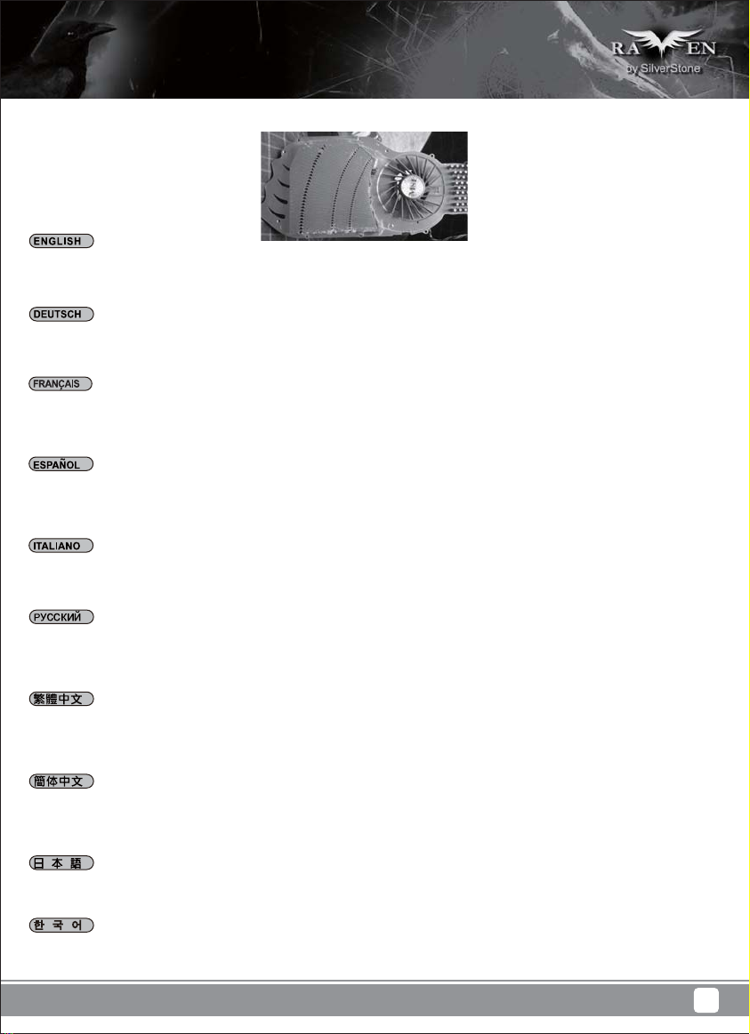
(1) Fan filter removal guide
Illustration: An example of a GPU cooler that is filled with dust and has lost most of its cooling performance RV05’s positive air pressure design is
an effective configuration that will reduce dust buildup inside the case. Small air particles or lint will accumulate over time on intake filters instead
of on the components inside the case. To maintain RV05’s excellent cooling performance for years to come, we recommend to clean all fan filters
regularly every three months or half a year (depending on your environment). Below are steps to remove fan filters.
Das vorteilhafte Luftdruckdesign des RV05 ist eine effektive Konfiguration, die Staubablagerungen innerhalb des Gehäuses vermindert. Im Laufe
der Zeit sammeln sich kleine Partikel und Fusseln an den Luftzufuhrfiltern, anstatt an den Komponenten im Gehäuseinneren, an. Sie können eine
jahrelange optimale Kühlleistung des RV05 gewährleisten, indem Sie alle Lüfterfilter regelmäßig alle drei bis sechs Monate reinigen (je nach
Umgebungsbedingungen). Nachstehend finden Sie die Schritte zur Entfernung der Lüfterfilter.
La conception à pression d'air positive du RV05 est une configuration efficace permettant de réduire l'accumulation de la poussière dans le boîtier.
De petites particules d'air ou de peluche vont s'accumuler avec le temps sur les filtres d'aspiration, et non sur les composants à l'intérieur du boîtier.
Pour conserver les excellentes performances de refroidissement du RV05 au fil des ans, nous vous recommandons de nettoyer l'ensemble des
filtres des ventilateurs, tous les trois ou six mois (selon votre environnement). Vous trouverez ci-dessous les étapes vous expliquant comment retirer
les filtres des ventilateurs.
El diseño de presión de aire positiva de la RV05 es una configuración efectiva que reducirá la acumulación de polvo dentro de la carcasa. Pequeñas
partículas de polvo ó pelusa se irán acumularán con el transcurso del tiempo en los filtros de entrada en lugar de en los componentes del interior
de la carcasa. Para mantener la excelente capacidad de refrigeración de la RV05 en años venideros, le recomendamos que limpie con regularidad
todos los filtros de los ventiladores cada tres meses ó seis meses (dependiendo de dónde viva). A continuación están los pasos para quitar los filtros
de los ventiladores.
Il design a pressione positiva di RV05 riduce considerevolmente gli accumuli di polvere all’interno del case. Le piccole particelle si accumulano
infatti sui filtri invece che sui componenti interni. Per mantenere le eccellenti prestazioni di raffreddamento di RV05 negli anni a venire vi
raccomandiamo di procedere ad una regolare pulizia dei filtri (con cadenza trimestrale o semestrale dipendentemente dall’ambiente un cui è disposto
il sistema). Di seguito i passi per la rimozione dei filtri.
Конструкция корпуса RV05 обеспечивает избыточное давление воздуха и , таким образом, имеет эффективную конфигурацию,
препятствующую скоплению пыли внутри корпуса. Небольшие частицы и волокна, содержащиеся в воздухе, со временем будут скапливаться
на впускных фильтрах, а не на компонентах, находящихся внутри корпуса. Для поддержания превосходного охлаждения компонентов в
корпусе RV05 в течение многих лет рекомендуется регулярно очищать все фильтры вентиляторов: раз в 3 месяца или раз в полгода
(в зависимости от условий окружающей среды). Ниже приведена процедура для удаления фильтров вентиляторов.
圖:被灰塵卡死的顯示卡散熱器
RV05的正壓差搭配濾網方式是經的起時間考驗最有效的防塵方式。在使用相當長一段時間後,棉屑灰塵或其他可能妨礙散熱效能的小異物只會卡在濾
網,而不是電腦內的元件上面。我們重視的散熱效能,是在您使用電腦長達2~3年後還能維持與全新的無異。為了維持這種散熱效能您只需要定期清理
濾網,而不是電腦裡面的元件。
視環境而定,我們建議您每6個月~1年必須清理濾網,以下是濾網的拆卸步驟。
图:被灰尘卡死的显示适配器散热器
RV05的正压差搭配滤网方式是经的起时间考验最有效的防尘方式。在使用相当长一段时间后,棉屑灰尘或其他可能妨碍散热效能的小异物只会卡在滤
网,而不是计算机内的组件上面。我们重视的散热效能,是在您使用计算机长达2~3年后还能维持与全新的无异。为了维持这种散热效能您只需要定期
清理滤网,而不是计算机里面的组件。
视环境而定,我们建议您每6个月~1年必须清理滤网,以下是滤网的拆卸步骤。
RV05の正圧設計は、ケース内のホコリの蓄積を減少させる有効な構造です。時と共に空気中の微粒子または糸くずはケース内のコンポーネト上
の代わりに取入れ口フィルタに溜まります。この先何年もの間RV05の素晴らしい冷却性能を維持するには、全てのファンを3ヶ月ないしは半年
(環境に依存) ごとに規則的に清掃するようお勧めします。以下は、ファンフィルタを取り外す手順です。
RV05의 양압 디자인은 케이스 내부에 먼지가 싸이는 것을 방지 하기 위한 효과적인 디자인입니다. 작은 분진이나 먼지는 케이스 내부에
있는필터에 시간에 따라 쌓이게 됩니다. RV05의 우수한 냉각 성능을 계속 유지하기 위헤서 매 3개월 혹은 6개월(사용환경에 따라)마다 필터
청소를권장합니다. 다음의 필터 제거 과정을 참고하세요.
28
Page 32

01
Main filter can be removed by
pulling it rearward from the front
lower panel
Главный фильтр можно снять,
потянув его назад от лицевой
нижней панели
02
Hauptfilter wird entfernt, indem er
von der unteren Frontplatte nach
hinten gezogen wird.
Le filtre principal peut être retiré
en le tirant vers l'arrière à partir
du panneau avant inférieur
El filtro principal se puede retirar
tirando hacia atrás desde el panel
frontal inferior
Il filtro principale può essere
rimosso tirandolo all'indietro dal
pannello frontale inferiore
Power supply filter is magnetic
so it can be removed easily
Der Netzteilfilter ist magnetisch
und kann somit einfach entfernt
werden.
主濾網請由下方往前抽出
主滤网请由下方往前抽出
メインフィルターは、フロントパ
ネルから後方に引いて取り外せ
ます。
주 필터는 뒤쪽으로 당겨 전면 하단
패널에서 분리할 수 있습니다.
Для фиксации фильтра блока
питания используется магнит,
поэтому от снимается легко
電源濾網是磁鐵的樣式,請直接拔
Le filtre de la source d'alimentation
est magnétique, et peut être
enlevé facilement
El filtro de la fuente de
alimentación es magnético,
luego se puede retirar fácilmente
Il filtro dell’alimentatore è
magnetico quindi può essere
rimosso facilmente
电源滤网是磁铁的样式,请直接拔
電源フィルターは磁石式なので
容易に取り外せます。
전원 공급장치 필터는 자석으로서
쉽게 분리할 수 있습니다.
29
Page 33

If you accidentally loose/damage filters or need additional ones for backup, please contact your local SilverStone retailers or distributors for purchasing
information:
http://www.silverstonetek.com/wheretobuy_all.php
Wenn Sie einen Lüfterfilter als Zusatz, zum Austausch bei Verlust oder Beschädigung oder einfach als Reserve erwerben möchten, suchen Sie
einfach auf unseren Internetseiten nach einem Händler oder Distributor in Ihrer Nähe:
http://www.silverstonetek.com/wheretobuy_all.php
Pour acheter un filtre du ventilateur au détail comme pour l’améliorer ou pour le remplacer en caisson de perte, de dommage ou simplement en
rechange, vous pouvez rechercher sur notre site Internet pour connaître les revendeurs ou les distributeurs les plus proches de chez vous:
http://www.silverstonetek.com/wheretobuy_all.php
Para comprar un filtro para ventilador como mejora o reemplazo en caso de pérdida, daño o simplemente como recambio, puede buscar en nuestra
página web para encontrar el distribuidor o vendedor autorizado más cercano:
http://www.silverstonetek.com/wheretobuy_all.php
Per acquistare un filtro della ventola al dettaglio per la sostituzione in caso di perdita, danni o semplicemente uno di riserva, è possibile cercare sul
nostro sito web i rivenditori o distributori più vicini:
http://www.silverstonetek.com/wheretobuy_all.php
На нашем сайте Вы найдете ближайшего торгового посредника или дистрибьютора, у которого можно приобрести фильтр вентилятора для
замены в случае потери или повреждения старого фильтра, или про запас.
http://www.silverstonetek.com/wheretobuy_all.php
添購濾網
如果您不慎遺失、人為損壞或只是想要多購買濾網備用。請與我們的經銷點聯絡進行購買。 請上SilverStone網站查詢各區域經銷
http://www.silverstonetek.com.tw/wheretobuy_all.php?area=tw
添购滤网
如果您不慎遗失、人为损坏或只是想要多购买滤网备用。请与我们的经销点联络进行购买。 请上SilverStone网站查询各区域经销
http://www.silverstonetek.com.tw/wheretobuy_all.php?area=tw
アップグレードまたは損失の場合の交換用、または単にバックアップとして小売ファン・フィルタを購入するには、最寄りの小売業者または卸売
業者を下記の当社ウェブサイトから検索できます。
http://www.silverstonetek.com/wheretobuy_all.php
팬 필터가 분실 또는 손상되어 소매로 팬 필터를 구입하거나 단순히 여분으로 구입하려는 경우, 당사의 웹사이트에서 가까운 판매점을
검색할 수 있습니다.
http://www.silverstonetek.com/wheretobuy_all.php
30
Page 34

(2) Fan removal guide
01
A
A. Remove both side panels
B. Remove main filter
A. Снимите боковые панели
B. Снимите главный фильтр
02
A. Entfernen Sie die beiden
Seitenteile.
B. Entnehmen Sie den
Hauptfilter.
B
A. Enlevez les deux panneaux
latéraux
B. Enlevez le filtre principal
A. Retire ambos paneles laterales
B. Retire filtro principal
A. Rimuovere entrambi i pannelli
laterali
B. Rimuovere il filtro principale
Unscrew screws holding the fans
to remove them
Lösen Sie die
Befestigungsschrauben des
Lüfters, nehmen Sie sie
heraus.
A. 已經拆卸左右板的狀態
B. 移除主濾網
A. 已经拆卸左右板的状态
B. 移除主滤网
A.両方の側面パネルを取り外し
ます。
B. メインフィルターを 取り外しま
す。
A. 두 개의 측면 패널을 모두
제거합니다.
B. 주 필터를 분리합니다.
Чтобы извлечь вентиляторы,
отверните винты их
крепления
卸除固定風扇的螺絲,卸除風扇
Dévissez les vis des ventilateurs
pour les enlever
Suelte los tornillos que soportan
los ventiladores para retirarlos
Svitare le viti che fissano le
ventole per rimuoverle
卸除固定风扇的螺丝,卸除风扇
ファンを 固 定 して いる ネ ジを外
して、取り外します。
팬을 고정하는 나사를 풀어
팬을 분리합니다.
31
Page 35

03
Using a smaller screw driver,
release screws holding
the speeds switches to remove
it from the case
Чтобы снять с корпуса
переключатели скорости
вентиляторов,
с помощью небольшой
отвертки отверните винты
их крепления
04
Follow the above steps in reverse to reinstall the
fans
Gehen Sie umgekehrt vor,um die Lüfter wieder zu
installieren.
Lösen Sie mit einem kleinen
Schraubendreher die
Schrauben, die die
Geschwindigkeitsschalter
halten, und nehmen Sie diese
aus dem Gehäuse.
A l’aide d’un petit tournevis,
enlevez les vis fixant les
commutateurs de vitesse pour
le retirer du châssis
Usando un destornillado
pequeño, suelte los tornillos
que sujetan los interruptores
de velocidad para
retirarlos de la carcasa
Utilizzando un piccolo
cacciavite,allentare le viti che
fissano gli interruttori di velocità
per rimuoverli dal case
Для установки вентиляторов на место повторите описанные
выше действия в обратном порядке
依照相反的順序安裝回去
卸除固定轉速切換開關的螺絲,
將轉速切換開關由前板的洞穿
出機殼(提醒您,應該要換更小
的螺絲起子)
卸除固定转速切换开关的螺丝,
将转速切换开关由前板的洞穿
出机壳(提醒您,应该要换更小
的螺丝起子)
小さいドライバ ーを 使って、回転
数スイッチを固定しているネジ
をケースから取り外します
소형 스크루드라이버를 사용하
여 속도 스위치를 고정하는
나사를 풀어 스위치를 케이스에서
분리합니다.
Suivez les étapes ci-dessus dans l'ordre inverse pour
réinstaller les ventilateurs
Siga los pasos anteriores de forma inversa para
reinstalar los ventiladores
Attenersi alle istruzioni di cui sopra in ordine inverso
per reinstallare le ventole
依照相反的顺序安装回去
ファン取り付けには以上のステップを逆順に行います。
팬을 도로 설치하려면 위의 단계를 역순으로 수행하십시오.
32
Page 36

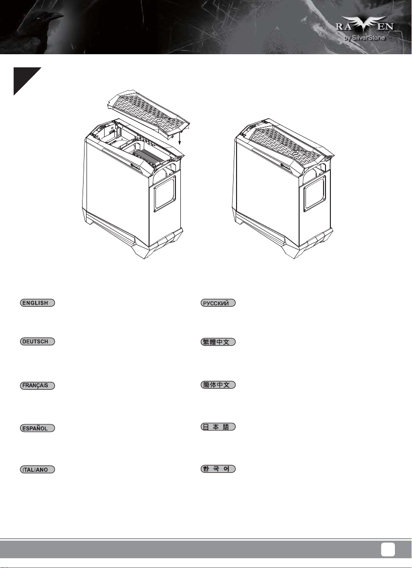
05
Downgrade to 120mm or 140mm fans:The bottom panel has
mounting holes designed for 120mm or 140mm fans, install
accordingly.
Auf 120- oder 140-mm-Lüfter herunterstufen In der Bodenplatte
befinden sich Montagebohrungen für 120 oder 140 mm Lüfter.
Verwenden Sie diese entsprechend.
Réduction vers ventilateurs de 120mm ou de 140mm Le panneau
du bas a des trous de fixation pour des ventilateurs de 120mm
ou de 140mm, installez comme nécessaire.
Bajar a ventiladores de 120mm ó 140mm El panel inferior tiene
agujeros de montaje diseñados para ventiladores de 120mm o
140mm, instale según sea necesario.
Retrocedere a ventole da 120 mm o 140 mm Il pannello
inferiore ha fori di montaggio progettati per ventole da 120 mm
o 140 mm; eseguire l’installazione di conseguenza.
33
Возможность использования 120-мм или 140-мм вентиляторов
На нижней панели имеются крепежные отверстия для
установки 120-мм или 140-мм вентиляторов, установите их
соответственно.
降級安裝120/140mm風扇:中央有向下相容的120與140mm風扇孔位,請
直接安裝
降级安装120/140mm风扇:中央有向下兼容的120与140mm风扇孔位,请
直接安装
120mmまたは140mmファンへのダウングレード底部パネルには、
120mmまたは140mmファンに対応して取り付け孔が開いているので、
それに従って取り付けます。
120mm 또는 140mm 팬으로 다운그레이드 가능 하단 패널에는
120mm 또는 140mm 팬에 사용할 수 있는 장착 구멍이 있습니다.
이에 맞춰 설치하십시오.
Page 37

Q&A
Q: If I have a tower-style CPU cooler, is it possible to run it without CPU fan installed?
A: It’s possible but for best balance of cooling and quietness, installing a fan directly on the CPU cooler is usually more effective than installing
exhaust fan on rear of the case.
F: Ich habe einen Tower-CPU-Kühler; ist es möglich, ihn ohne installierten CPU-Lüfter laufen zu lassen?
A: Dies ist möglich; zur optimalen Balance aus Kühlung und geräuscharmem Betrieb ist es jedoch üblicherweise sinnvoller, einen Lüfter direkt am
CPU-Kühler zu installieren, anstatt einen Abluftlüfter am Gehäuse anzubringen.
Q: Si j'ai un dissipateur de processeur de type tour, est-il possible de l'utiliser sans ventilateur?
R: C’est possible, mais pour un équilibre idéal entre refroidissement et silence, l’installation d’un ventilateur directement sur le refroidisseur de l’unité
centrale est plus efficace que l’installation d’un ventilateur d’extraction sur le châssis.
P: ¿Si tengo un disipador para CPU tipo torre, ¿es posible usarlo sin un ventilador para CPU instalado?
R: Es posible pero para el mejor equilibrio entre refrigeración y sonoridad, instalar un ventilador directamente en el disipador de la CPU suele ser
más efectivo que instalar un ventilador de salida en la carcasa.
D: Se possiedo un dissipatore per CPU a torre, è possibile utilizzarlo senza montare le ventole in dotazione?
R: Per un miglior equilibrio tra raffreddamento e silenziosità, l’installazione di una ventola direttamente sul dissipatore della CPU solitamente è più
efficace dell’installazione di una ventola di scarico dell’aria sul case.
B: При наличии процессорного кулера башенного типа можно ли обойтись без установки процессорного вентилятора?
O: Это возможно, но для достижения оптимального баланса охлаждения и бесшумности работы установка вентилятора непосредственно
на кулер процессора обычно приводит к более эффективному результату, чем установка вытяжного вентилятора на корпусе.
Q: 我使用高塔型的Cooler, 可不可以不用裝風扇?
A: 可能不會過熱,但是以噪音效能相比而言,將風扇安裝在CPU Cooler上會比安裝在後抽風扇更有效率。
Q: 我使用高塔型的Cooler, 可不可以不用装风扇?
A: 可能不会过热,但是以噪音效能相比而言,将风扇安装在CPU Cooler上会比安装在后抽风扇更有效率。
Q: タワータイプCPUクーラーがある場合、CPUファンをインストールせずに稼働することは可能ですか?
A: 冷却と静音性のバランスを考えると、一般的にCPUクーラーの上に直接ファンを設置する方が、ケースに排気ファンを設置するより効率的です。
Q: 만약 타워형 CPU 쿨러를 사용할 경우 CPU팬 없이 사용 가능할까요 ?
A: 이는 가능한 방법이지만 냉각과 저소음을 균형을 최상으로 맞추려면 일반적으로 팬을 CPU 쿨러에 직접 설치하는 것이 배기 팬을 케이스에
설치하는 것보다 효과가 더 좋습니다.
34
Page 38

Q: I have an all-in-one liquid cooler, where should I install the radiator?
A: Most should fit in the top 120mm fan area. If you have larger cooler, we recommend installing it on the bottom panel.
F: Ich habe einen All-in.One-Flüssigkeitskühler. Wo soll ich ihn installieren?
A: Die meisten passen in den oberen 120 mm Lüfterbereich. Ist der Kühler größer, empfehlen wir Ihnen, ihn auf der Bodenplatte zu montieren.
Q : J'ai un refroidisseur liquide tout-en-un, où puis-je installer le radiateur ?
R : La plupart devraient rentrer dans la zone du ventilateur supérieur de 120mm. Si vous avez un refroidisseur plus grand, nous vous recommandons
de l'installer sur le panneau inférieur.
P: ¿Tengo una refrigeración líquida todo-en-uno, ¿dónde debería instalar el radiador?
R: La mayoría debería encajar en la zona superior para ventiladores de 120mm. Si tiene un refrigerador más grande, le recomendamos instalarlo
en el panel inferior.
D: Ho un dispositivo di raffreddamento a liquido tutto in uno; dove devo installare il radiatore?
R: La maggior parte dovrebbe adattarsi nell'area superiore della ventola da 120 mm. Se il dissipatore di calore ha dimensioni maggiori, si raccomanda
di installarlo sul pannello inferiore.
В: У меня имеется моноблочный кулер с жидкостным охлаждением, где следует установить радиатор?
О: Большинство из них можно установить в зоне 120-мм вентиляторов. Кулер с большими размерами мы рекомендуем устанавливать на
нижней панели.
Q: 我購買了簡易的整合水冷散熱器,水冷排安裝在哪邊比較適合?
A: 1X120的水冷排可以安裝在上方;超過這規格我們建議安裝在機殼下方。
Q: 我购买了简易的整合水冷散热器,水冷排安装在哪边比较适合?
A: 1X120的水冷排可以安装在上方;超过这规格我们建议安装在机壳下方。
Q: 一体型液冷クーラーを持っていますが、ラジエターはどこに取り付けたらいいですか?
A: 大部分は上部120mmファンのエリアに適合します。より大型のクーラーであれば、底部パネルへの取り付けを推奨します。
Q: 일체형 수냉식 쿨러가 있는데, 라디에이터를 어디에 설치해야 합니까?
A: 대부분은 상단 120mm 팬 영역에 맞습니다. 쿨러의 크기가 더 클 경우 이를 하단 패널에 설치할 것을 권장합니다.
35
Page 39

Q: Can I remove and clean the fan filter while the computer is turned on?
A: Yes, but to reduce the chance of foreign objects touching and damaging the spinning fans while the system is on, we recommend doing so quickly.
F: Kann ich den Lüfterfilter entfernen und reinigen, während der Computer eingeschaltet ist?
A: Ja, aber damit bei eingeschaltetem System keine Gegenstände mit den rotierenden Lüftern in Kontakt kommen und diese beschädigen, empfehlen
wir, dies schnell zu erledigen.
Q : Puis-je enlever et nettoyer le filtre du ventilateur lorsque l’ordinateur est allumé ?
R : Oui, mais pour réduire le risque d’objet touchant et endommageant les ventilateurs en marche lorsque le système est allumé, nous vous
recommandons de le faire rapidement.
P: ¿Posso rimuovere e pulire il filtro della ventola mentre il computer è acceso?
R: Sì, ma per ridurre le possibilità che corpi estranei tocchino e danneggino le ventole in funzione mentre il sistema è acceso, si raccomanda di
eseguire rapidamente l’operazione.
D: Posso rimuovere e pulire il filtro della ventola mentre il computer è acceso?
R: Sì, ma per ridurre le possibilità che corpi estranei tocchino e danneggino le ventole in funzione mentre il sistema è acceso, si raccomanda di
eseguire rapidamente l’operazione.
В: Можно ли снимать и очищать фильтр вентилятора при включенном компьютере?
О: Можно, но во избежание попадания посторонних предметов, которые могут повредить вращающиеся лопасти вентиляторов при
включенной системе, мы рекомендуем выполнять эту операцию быстро.
Q: 可以在開機狀態下清理前面濾網嗎?
A: 可以。但開機時抽出濾網後就暫時沒有濾網保護,為避免異物觸碰或損傷運轉中的風扇,我們建議盡量縮短您的作業時間。
Q: 可以在开机状态下清理前面滤网吗?
A: 可以。但开机时抽出滤网后就暂时没有滤网保护,为避免异物触碰或损伤运转中的风扇,我们建议尽量缩短您的作业时间。
Q: コンピューター稼働中に、ファンフィルターを外して清掃してもいいですか?
A: はい。ただしシステム動作中に異物が触れて回転中のファンに損傷を与えないよう、素早く処理するようお勧めします。
Q: 컴퓨터가 켜진 상태에서 팬 필터를 분리하여 청소해도 됩니까?
A: 예. 그러나 시스템이 켜 있는 동안 이물질이 회전 팬에 닿아 팬을 손상시킬 확률을 줄이기 위해 빨리 처리할 것을 권장합니다.
36
Page 40

Q: When I turn on the computer, why don’t the 180mm fans spin (or they spin slower than expected)?
A: If your fans are connected to the motherboard, we suggest turning off temperature control function in the BIOS. If you want to use temperature
control function on your motherboard, we recommend setting the RV05’s physical fan speed switch to high for a lower starting voltage and a wider
range of control. If the fans still do not spin, please contact reseller or SilverStone to arrange for replacement.
F: Wenn ich den Computer einschalte, drehen die 180-mm-Lüfter nicht (oder langsamer als erwartet); warum?
A. Falls Ihr Lüfter mit dem Motherboard verbunden ist, sollten Sie die Temperatursteuerungsfunktion im BIOS abschalten. Falls Sie die
Temperatursteuerungsfunktion an Ihrem Motherboard nutzen möchten, empfehlen wir, den physikalischen Lüftergeschwindigkeitsschalter desRV05
auf hohe Geschwindigkeit einzustellen; dadurch werden eine geringere Startspannung und ein breiterer Steuerungsbereich ermöglicht. Falls die
Lüfter dennoch nicht drehen, wenden Sie sich zum Ersatz bitte an Ihren Händler oder SilverStone.
Q: Lorsque j’allume l’ordinateur, pourquoi les ventilateurs de 180mm ne se mettent-ils pas à tourner (ou à une vitesse moindre) ?
R: Si votre ordinateur est connecté à la carte mère, nous vous suggérons de désactiver la fonction de contrôle de température du BIOS. Si vous
souhaitez utiliser la fonction de contrôle de la température de la carte mère, nous vous recommandons de régler le commutateur de vitesse du
ventilateur physique du RV05 sur Haut pour une tension au démarrage moins élevée et pour une gamme de contrôle plus importante. Si le
ventilateur ne tourne toujours pas, veuillez contacter le revendeur ou Silverstone pour convenir d'un remplacement.
P: ¿Cuándo enciendo el ordenador, por qué no giran los ventiladores de 180mm (o giran más lento de lo esperado)?
R: Si su ventilador está conectado a la placa base, le sugerimos que apague la función de control de temperatura de la BIOS. Si desea usar la función
de control de temperatura de su placa base, le recomendamos que fije el interruptor de velocidad del ventilador físico del RV05 en alto para un
voltaje de inicio menor y un rango de control más amplio. Si los ventiladores todavía no giran, por favor contacte con su distribuidor ó con SilverStone
para conseguir un reemplazo.
D: Quando accendo il computer, perché le ventole da 180 mm non girano (o girano più lentamente del previsto)?
R: Falls Ihr Lüfter mit dem Motherboard verbunden ist, sollten Sie die R. Se la ventola è collegata alla scheda madre, si consiglia di disattivare la
funzione di controllo della temperatura nel BIOS. Se si vuole usare la funzione di controllo della temperatura sulla scheda madre, si raccomanda
di impostare l’interruttore fisico di RV05 sull’alta velocità per una tensione d’avvio più bassa ed una gamma di controllo più ampia. Se la ventola
continua a non funzionare, contattare il rivenditore o SilverStone per organizzare per la sostituzione.
В: Почему при включении компьютера не вращаются 180-мм вентиляторы (или вращаются медленнее, чем ожидается)?
O: Если вентилятор подключен к системной плате, мы предлагаем отключить функцию температурного контроля в BIOS. Если вы хотите
использовать функцию температурного контроля с системной платой, мы рекомендуем установить переключателем скорости вентилятора
в корпусе RV05 высокую скорость вращения для снижения напряжения запуска и расширения диапазона контроля. Если и в этом случае
вентилятор не вращается, обратитесь к продавцу или в компанию SilverStone для его замены.
Q: 開機了,主要180mm風扇不會運轉(或轉得很慢)?
A: 如果您是把風扇插頭是插在主機板上。建議您可以先將主機板BIOS的風扇溫控功能關掉。如果您想利用主機板的溫控功能,建議您應該把風扇的轉
速切到高轉,以得到更低的啟動電壓與更大的控制範圍。如果無論如何風扇都不會運轉,請儘速聯絡購買處,處理換貨事宜。
Q: 开机了,主要180mm风扇不会运转(或转得很慢)?
A: 如果您是把风扇插头是插在主板上。建议您可以先将主板BIOS的风扇温控功能关掉。如果您想利用主板的温控功能,建议您应该把风扇的转速切到
高转,以得到更低的启动电压与更大的控制范围。如果无论如何风扇都不会运转,请尽速联络购买处,处理换货事宜。
Q: コンピュータを起動させた後、180mmファンが回転しない(または思ったより遅く回転する)のはなぜでしょうか?
A: あなたのファンがマザーボードに接続しているならばA.と、我々はBIOSで温度調節機能をオフにするためにあなたに示唆します。あなたがあな
たのマザーボードの上で温度調節機能を使用したいならば、我々は低い立上げ電圧と支配のより広い範囲のためにRV05の身体的なファン速度ス
イッチを高さに設定するとあなたに勧めます。扇風機がまだ回転しないならば、置き換えを手配するために、再販業者またはシルバーストーン
と交信してください。
Q: 컴퓨터를 켰는데도 180mm 팬이 회전하지 않습니다. (또는 회전 속도가 예상보다 느립니다.)?
A: 팬을 메인보드에 연결했다면, BIOS에서 온도 제어 기능을 끌 것을 제안합니다. 메인보드에서 온도 제어 기능을 사용하고 싶을 경우, 더
낮은 전압에서 시작하고 더 광범위하게 제어할 수 있도록 RV05의 실제 팬 속도 스위치를 고속으로 설정할 것을 권장합니다. 팬이 여전히
회전하지 않으면, 대리점 또는 SilverStone에 연락하여 교체하도록 하십시오.
37
Page 41

Q: I want to install customized liquid cooling system, do you have any recommendations?
A: If you are thinking about installing a triple 120mm radiator, we highly recommend a dual 180mm radiator such as the “Magicool Dual 180” instead.
Although both types of radiators have the same length, the dual 180mm radiator has approximately 50% larger surface area for much higher
performance potential.
F: Ich möchte ein angepasstes Flüssigkeitskühlsystem installieren. Gibt es diesbezüglich irgendwelche Empfehlungen?
A: Wir empfehlen Ihnen anstelle der Installation eines dreifachen 120 mm Kühlers die Verwendung eines zweifachen 180 mm Kühlers, beispielsweise
“Magicool Dual 180”. Obwohl beide Kühlertypen etwa die gleiche Länge haben, verfügt der zweifache 180mm Kühler über eine um etwa 50%
größere Oberfläche und bietet so eine viel höhere Kühlleistung.
Q: Je souhaite installer un système de refroidissement liquide personnalisé, avez-vous des recommandations ?
R: Si vous pensez installer un triple radiateur de 120mm, nous vous recommandons fortement d'utiliser un double radiateur de 180mm comme le
“Magicool Dual 180” à la place. Bien que les deux types de radiateurs sont de même longueur, le double radiateur de 180mm a environ 50% plus
de surface pour des meilleures performances.
P: Quiero instalar un sistema de refrigeración líquida personalizado, ¿tiene recomendaciones?
R: Si está pensando en instalar un radiador triple de 120mm, le recomendamos encarecidamente en su lugar un radiador dual de 180mm como el
“Magicool Dual 180”. Aunque ambos tipos de radiadores tienen la misma longitud, el radiador dual de 180mm tiene aproximadamente una
superficie un 50% más grande para un mayor potencial de rendimiento.
D: Voglio installare un sistema personalizzato di raffreddamento a liquido, ci sono delle raccomandazioni?
R: Se si sta pensando di installare una radiatore con ventole da 120 mm, si raccomanda vivamente di installare invece un radiatore con due ventole
da 180 mm, come “Magicool Dual 180”. Sebbene entrambi i tipi di radiatore abbiano la stessa lunghezza, il radiatore con due ventole da 180 mm
ha una superficie più grande di circa il 50 % per un potenziare di prestazioni di gran lunga maggiore.
В: Я хочу установить заказную систему жидкостного охлаждения, какие рекомендации вы можете предложить?
О: Если вы намерены установить тройной 120-мм радиатор, мы настоятельно рекомендуем вместо него установить двойной 180-мм
радиатор типа "Magicool Dual 180". Хотя оба типа радиаторов имеют одинаковую длину, зона поверхности двойного 180-мм радиатора
приблизительно на 50% больше, что обеспечивает улучшенные рабочие характеристики.
Q: 我需要安裝DIY水冷,有沒有什麼建議?
A: 如果您考慮在前方安裝一個3X120風扇規格的水冷排,我們建議您可以考慮Magicool Dual 180 Radiator。雖然長度一樣,但是從面積算上來2X180
水冷排比3X120多了足足有50%,可以提供更大的冷卻效能。
Q: 我需要安装DIY水冷,有没有什么建议?
A: 如果您考虑在前方安装一个3X120风扇规格的水冷排,我们建议您可以考虑Magicool Dual 180 Radiator。虽然长度一样,但是从面积算上来2X180
水冷排比3X120多了足足有50%,可以提供更大的冷却效能。
Q: カスタム化された液冷システムをインストールしたいのですが、何かお勧めがありますか?
A: 3つの120mmラジエターを取り付けることを考慮されているのであれば、代わりに「Magicool Dual 180」のようなデュアル180mmラジエターの
設置を強くお勧めします。双方のタイプのラジエターは同じ長さですが、デュアル180mmラジエターは約50%大きな表面積があり、より大きな
潜在性能を有します。
Q: 사용자 지정 수냉 시스템을 설치하려고 합니다. 권장할 만한 사항이 있습니까?
A: 트리플 120mm 라디에이터 설치를 고려하고 있는 경우 트리플 대신 “Magicool Dual 180”과 같이 듀얼 180mm 라디에이터를 적극
권장합니다. 두 가지 유형의 라디에이터 모두 길이가 동일하지만 듀얼 180mm 라디에이터의 경우 면적이 약 50% 정도 넓어 성능이 훨씬
높을 가능성이 있습니다.
38
Page 42

Warranty Information
This product has a limited 1 year warranty in North America and Australia.
For information on warranty periods in other regions, please contact your reseller or SilverStone authorized distributor.
Warranty terms & conditions
1. Product component defects or damages resulted from defective production is covered under warranty.
Defects or damages with the following conditions will be fixed or replaced under SilverStone Technology’s jurisdiction.
a) Usage in accordance with instructions provided in this manual, with no misuse, overuse, or other inappropriate actions.
b) Damage not caused by natural disaster (thunder, fire, earthquake, flood, salt, wind, insect, animals, etc…)
c) Product is not disassembled, modified, or fixed. Components not disassembled or replaced.
d) Warranty mark/stickers are not removed or broken.
Loss or damages resulted from conditions other than ones listed above are not covered under warranty.
2. Under warranty, SilverStone Technology’s maximum liability is limited to the current market value for the product (depreciated value, excluding
shipping, handling, and other fees). SilverStone Technology is not responsible for other damages or loss associated with the use of product.
3. Under warranty, SilverStone Technology is obligated to repair or replace its defective products. Under no circumstances will SilverStone
Technology be liable for damages in connection with the sale, purchase, or use including but not limited to loss of data, loss of business, loss of
profits, loss of use of the product or incidental or consequential damage whether or not foreseeable and whether or not based on breach of warranty,
contract or negligence, even if SilverStone Technology has been advised of the possibility of such damages.
4. Warranty covers only the original purchaser through authorized SilverStone distributors and resellers and is not transferable to a second hand
purchaser.
5. You must provide sales receipt or invoice with clear indication of purchase date to determine warranty eligibility.
6. If a problem develops during the warranty period, please contact your retailer/reseller/SilverStone authorized distributors or SilverStone
http://www.silverstonetek.com.
Please note that: (i) You must provide proof of original purchase of the product by a dated itemized receipt; (ii) You shall bear the cost of shipping
(or otherwise transporting) the product to SilverStone authorized distributors. SilverStone authorized distributors will bear the cost of shipping
(or otherwise transporting) the product back to you after completing the warranty service; (iii) Before you send the product, you must be issued a
Return Merchandise Authorization (“RMA”) number from SilverStone. Updated warranty information will be posted on SilverStone’s official website.
Please visit http://www.silverstonetek.com for the latest updates.
Additional info & contacts
For North America (usasupport@silverstonetek.com)
SilverStone T echnology in North America may repair or replace defective product with refurbished product that is not new but has been functionally tested.
Replacement product will be warranted for remainder of the warranty period or thirty days, whichever is longer. All products should be sent
back to the place of purchase if it is within 30 days of purchase, after 30 days, customers need to initiate RMA procedure with SilverStone Technology
in USA by first downloading the “USA RMA form for end-users” form from the below link and follow its instructions.
http://silverstonetek.com/contactus.php
For Australia only (support@silverstonetek.com)
Our goods come with guarantees that cannot be excluded under the Australian Consumer Law.
You are entitled to a replacement or refund for a major failure and for compensation for any other reasonably foreseeable loss or damage.
You are also entitled to have the goods repaired or replaced if the goods fail to be of acceptable quality and the failure does not amount to a major failure.
Please refer to above “Warranty terms & conditions” for further warranty details.
SilverStone Technology Co., Ltd. 12F No. 168 Jiankang Rd., Zhonghe Dist., New Taipei City 235 Taiwan R.O.C. + 886-2-8228-1238
(standard international call charges apply)
For Europe (support.eu@silverstonetek.de)
For all other regions (support@silverstonetek.com)
39
Page 43

Page 44

G11221470
 Loading...