

Page 1

RV03
MANUAL
Page 2
SERIES
SERIES
Redefining the rules
Installation and system optimization guide:
The following manual and guides were carefully prepared by the RAVEN engineering team to help
you maximize the potential of your SilverStone product. Please keep this manual for future reference
when upgrading or performing maintenance on your system. A copy of this manual can also be
downloaded from our website at:
http://www.silverstonetek.com
Specifications
Disassemble Chart
Installation guide
Connector definition
Front I/O connector guide
Component size limitations
Recommended cooling device setup and selection
Cable routing
Fan speed adjustment
Upgrade and maintenance
Q & A
1
P.2
P.3
P.5
P.16
P.18
P.19
P.28
P.30
P.30
P.33
P.44
Page 3
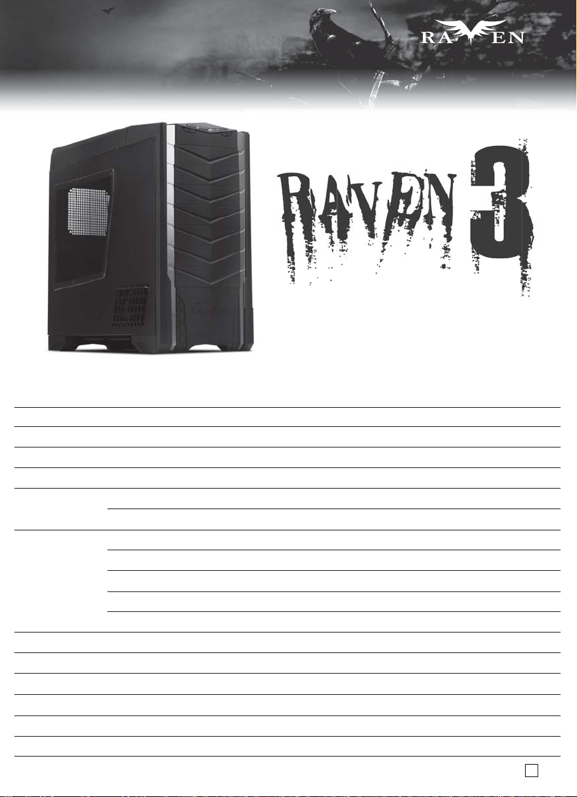
Specifications
SERIES
SERIES
Redefining the rules
Model
Material
Color
Motherboard
Drive Bay
Cooling System
Expansion Slot
Front I/O Port
Power Supply
Expansion Card
Net Weight
Dimension
SST-RV03B (black), SST-RV03B-W (black + window)
Reinforced plastic outer shell, 0.8mm Steel body
Matte black
SSI EEB, SSI CEB, Extended ATX, ATX, Micro ATX
Exposed
Internal
bottom
Top
Front
Right
Rear
8
USB 3.0 x 2 (backwards compatible with USB 2.0), audio x 1, MIC x 1
1 x optional standard PS2 (ATX), depth limit 180mm
Compatible with expansion cards up to 13.58 inches
11.4kg
235mm (W) x 522mm (H) x 570mm (D)
5.25" x 7
3.5" x 10 (6 from 5.25” adapters), 2.5” x 2 for SSD
2 x 180mm AP181 fan 700/1200rpm, 18/34dBA (compatible with 3 x 120mm fan)
1 x 120mm exhaust fan, 900rpm, 18dBA
4 x 120mm fan slot
1 x 120mm fan slot
1 x 120mm fan slot
2
Page 4
SERIES
SERIES
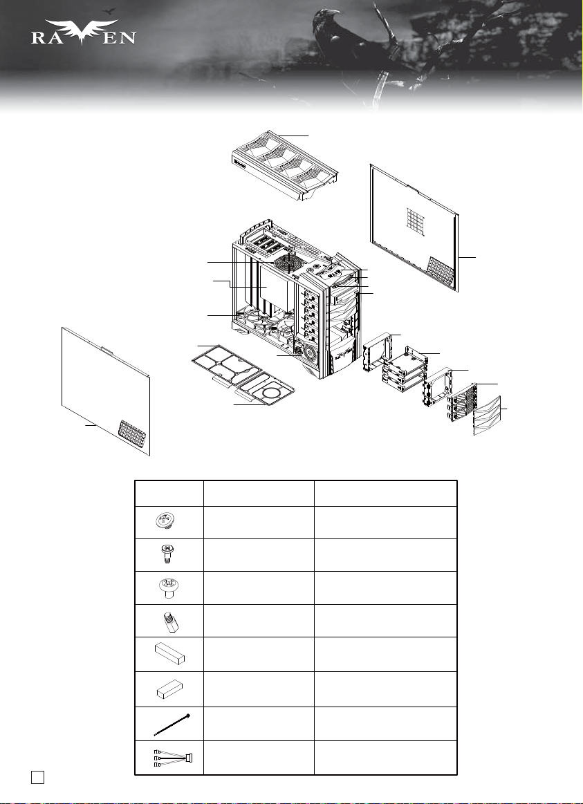
Disassemble Chart
LEFT SIDE PANEL
TOP COVER
12025 FAN
E - ATX MB
(OPTION)
18032 FAN x 2
18032 FAN FILTER
PS2 PSU
(OPTION)
PSU FILTER
PICTURE ITEM PURPOSE
SCREW A
SECURE 5.25” DRIVE AND
2.5” HARD DRIVE
FRONT I/O
POWER
RESET
5.25” DRIVE BAY x 7
120 FAN BKT
RIGHT SIDE PANEL
3.5” DRIVE BAY x 3
120 FAN BKT
5.25” DRIVE BAY
FILTER x 7
5.25” DRIVE BAY
COVER x 7
SCREW B SECURE HARD DRIVE
SCREW C
SECURE POWER SUPPLY
AND MOTHERBOARD
SCREW D MOTHERBOARD STANDOFF
DOUBLE-SIDED TAPE
SECURE OPTICAL
DRIVE COVER
RUBBER OPTICAL DRIVE EJECT
WIRE TIES SECURE WIRES
FAN CABLE POWER ADAPTER
3
Page 5
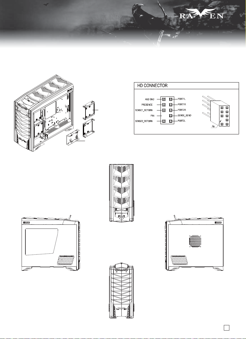
Disassemble Chart
3.5” DRIVE BAY x 4
2.5” DRIVE BAY x 2
SERIES
SERIES
TOP
LEFT SIDE RIGHT SIDE
FRONT
4
Page 6
SERIES
SERIES
lnstallation Guide
Before you begin, please make sure that you
(1) have all components collected.
(2) check that all components do not have compatibility problems with each other or with the case.
(3) if possible, assemble the components outside the case first to make sure they are working.
(4) keep the motherboard manual ready for reference during installation.
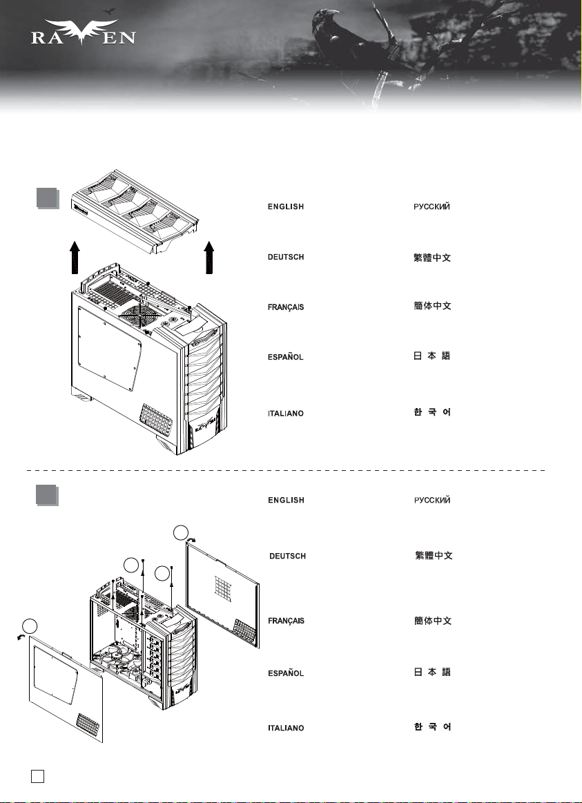
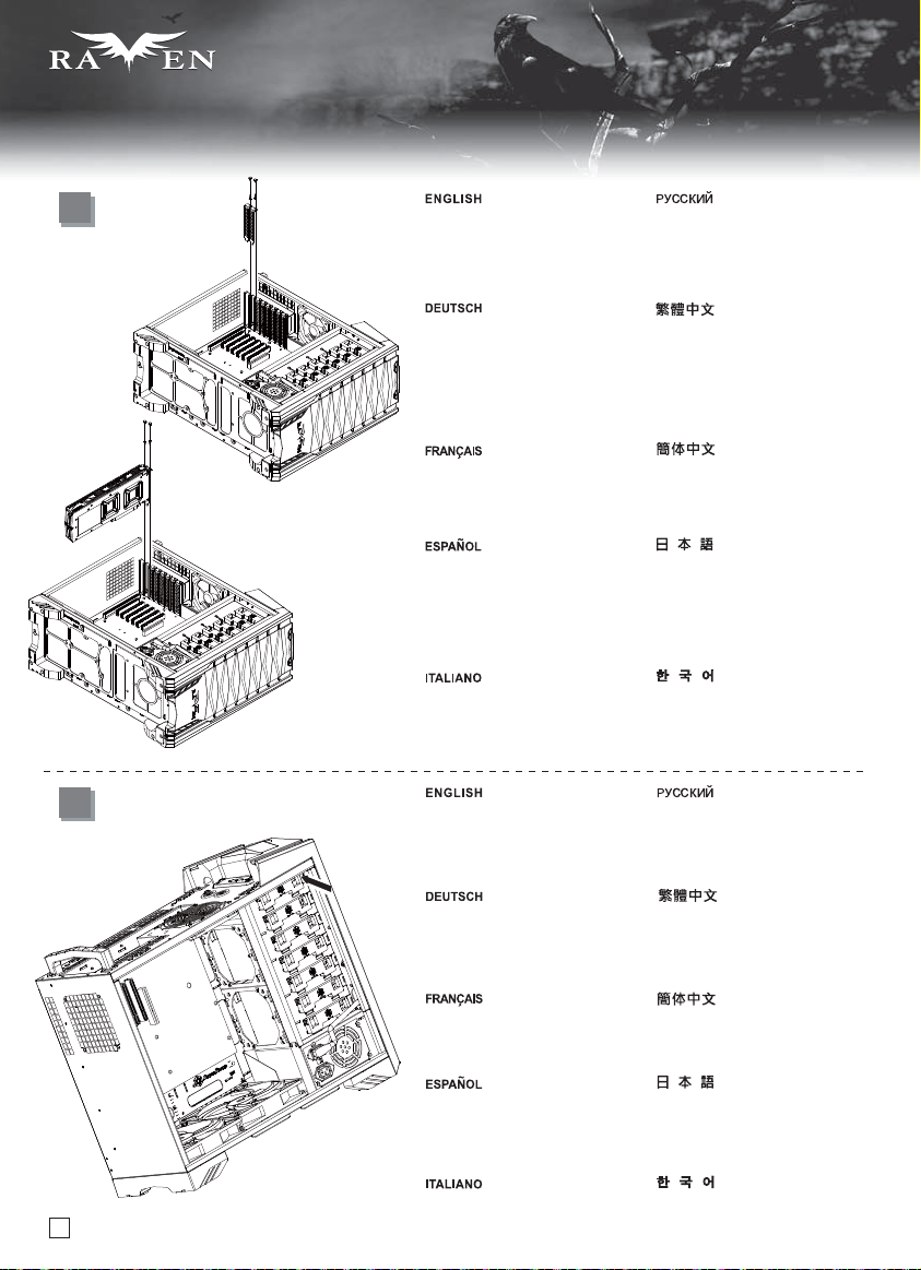
1
Pull top plastic cover off the case
in the direction as illustrated by
the arrow.
Сдвиньте верхнюю пластиковую
крышку корпуса в направлении,
указанном стрелкой.
Ziehen Sie die obere Kunststoffabdeckung
in Pfeilrichtung vom Gehäuse ab
(siehe Abbildung).
Tirer le cache en plastique supérieur
vers l'extérieur du boitier comme
illustré par la flèche.
Quite la cubierta superior de plástico
de la carcasa en la dirección que
muestra la flecha.
Rimuovere il cover superiore in
plastica come mostrato in figura.
請按箭頭方向用力,取出上蓋。
请按箭头方向用力,取出上盖。
矢印で示される方向に、ケースからの
一番上のプラスチックカバーを抜き取
ります。
상부의 플라스틱 커버를 화살표
방향과 같이 당겨서 제거 합니다.
2
Remove four thumb screws from the
top to pull the side panels away from
2
1
1
2
the case.
Entfernen Sie die vier Flügelschrauben
von der Oberseite, ziehen Sie die
seitlichen Blenden vom Gehäuse
ab.
Retirer les quatre vis à main du
dessus pour retirer les panneaux
latéraux du boîtier.
Чтобы снять боковые панели
корпуса, открутите сверху четыре
винта с рифлёной головкой .
先鬆開4顆手扭螺絲,再旋轉取出
左右側板。
先松开4颗手扭螺丝,再旋转取出
左右侧板。
Quite los cuatro tornillos de la parte
superior para liberar los paneles
laterales de la carcasa.
Svitare le 4 viti sulla parte superiore
per rimuovere i pannelli laterali.
5
ケースから側面パネルを取り外すため、
つまみネジ4本を上部から外します。
싸이드 패널을 케이스에서 제거하기위해
4개의 손나사를 상부에서 제거합니다.
Page 7
SERIES
SERIES
lnstallation Guide
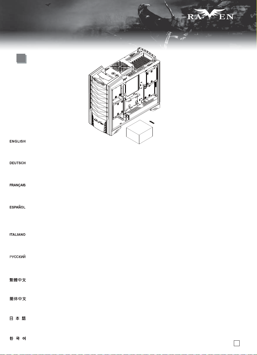
3
PSU
Insert the power supply from the right side of the chassis. Since the 5.25” drive bay is located directly above the power supply cage,
we designed the mounting holes for power supply to fit only one direction. Please double check the mounting holes before installation.
Normally a power supply with 120mm fan or larger will have its fan pointing down when installed.
Setzen Sie das Netzteil von der rechten Seite des Gehäuses ein. Da sich der 5,25 Zoll-Laufwerkseinschub direkt oberhalb des Netzteilkäfigs befindet,
gestalteten wir die Montagelöcher des Netzteils so, dass es nur in eine Richtung passt. Prüfen Sie die Montagelöcher vor der Installation genau.
Üblicherweise wird ein Netzteil mit einem mindestens 120 mm großen Lüfter so installiert, dass dieser bei der Installation nach unten zeigt.
Insérez l’alimentation par le côté droit du boîtier. Depuis que la baie 5.25” est situé directement au-dessus de la cage de l'alimentation, nous avons placés
les trous de montage pour qu'on puisse seulement la monter dans un sens. Veuillez bien vérifier les trous de montage avant l'installation. Normalement une
alimentation ayant un ventilateur de 120mm ou plus aura son ventilateur vers le bas lorsqu'elle sera installée.
Inserte la fuente de alimentación desde el lado derecho del chasis. Ya que la bahía para dispositivos de 5,25” está localizada justo sobre la carcasa de la
fuente de alimentación, diseñamos los agujeros del montaje de la fuente de alimentación para que pudieran usarse sólo desde una dirección. Por favor,
asegúrese de que los agujeros están en el lugar correcto antes de proceder a la instalación. Lo normal es que una fuente de alimentación con un ventilador
de 120mm ó mayor tendrá su ventilador hacia abajo cuando sea instalado.
Inserire l’alimentatore dalla parte destra dello chassis. Dal momento che i bay da 5,25” sono posti direttamente al disopra della struttura di ritenzione della
PSU, i fori di fissaggio sono stati disegnati per accettare l’alimentatore in una sola direzione. Controllare bene i fori di fissaggio prima del montaggio dell’unità
di alimentazione. Normalmente un alimentatore dotato di una ventola da 120mm o più grande avrà la ventola posta in basso una volta installato.
Установите блок питания с правой стороны корпуса. Та к как отсек для 5,25-дюймовых приводов расположен непосредственно над кронштейном
блок а питания, монтажные отверстия позволяют установить блок питания толь ко в одном направлении. Перед установкой дважды проверьте
монтажные отверстия. Обычно блок питания со 120-мм или более крупным вентилятором после установки будет расположен
將電源由右側塞入機殼,請注意, 由於電源上方就是5.25”槽, 所以我們沒有設計正反裝, 請先確認好螺絲鎖固孔位再塞入,一般使用12cm以上風扇的電源而言,
風扇朝下。
将电源由右侧塞入机壳,请注意, 由于电源上方就是5.25”槽, 所以我们没有设计正反装, 请先确认好螺丝锁固孔位再塞入,一般使用12cm以上风扇的电源而言,
风扇朝下。
電源はケースの右側から入れます。5.25インチドライブベイが電源ケージのすぐ上に位置するので、取り付け用穴は電源が一つの方向にのみ適合するように
設計されています。インストール前に取り付け穴を確認してください。通常、120mm以上のファンを備える電源は、インストール時にファンは下向きとなります。
전원을 우측에서 케이스로 들여보냅니다. 전원 상방이 5.25” 장치 슬롯이기 때문에, 정반 설치로 설계하지 않았습니다. 먼저 나사
잠금 위치를 확인한 후 설치하십시오. 일반적으로 12cm 이상 팬의 전원은 팬이 아래로 향합니다.
вентилятором вниз.
6
Page 8
SERIES
SERIES
lnstallation Guide
4
Secure the screws of power supply
and connect the 90 degree power
cord.
Ziehen Sie die Schrauben des Netzteils
fest; schließen Sie das um 90 Grad
angewinkelte Netzkabel an.
Serrez les vis de l'alimentation et
brancher le cordon d'alimentation
avec le connecteur à 90 degrés.
Fije los tornillos de la fuente de
alimentación y conecte el cable
de potencia de 90 grados.
Закрепите блок питания винтами
и подсоедините угловой кабель
питания (90 градусов).
鎖上電源螺絲,插上電源90度接線。
锁上电源螺丝,插上电源90度接线。
電源のネジを固定し、90度電源コード
を接続します。
1
1
Fissare l’alimentatore con le viti e
collegare il cavo di alimentazione
con il connettore a 90°.
파워 서플라이를 나사로 고정시킨 후,
90도 꺽인 파워 코드를 연결합니다.
5
Insert the I/O shield included with
your motherboard.
Bringen Sie das bei Ihrem Motherboard
mitgelieferte E/A-Blech an.
Вставьте крышку панели вводавывода, входящую в комплект
поставки материнской платы.
將主機板I/O彈片裝上機殼。
Insérez la plaque des entrées/sorties
inclus avec votre carte mère.
Inserte el escudo E/S incluido con
su placa base.
Inserire la mascherina posteriore
della scheda madre.
7
将主机板I/O弹片装上机壳。
マザーボードに付属のI/Oシールドを
挿入します。
메인보드에서 제공하는 I/O 쉴드를
삽입합니다.
Page 9
SERIES
SERIES
lnstallation Guide
6
Secure the standoffs with the screws D on the motherboard tray as required. Install the motherboard and secure with screw C.
Befestigen Sie die Abstandshalter mit den Schrauben D wie erforderlich am Motherboard-Einschub. Installieren Sie das Motherboard,
befestigen Sie es mit Schraube C.
Fixez les plots avec les vis de type D sur le plateau support de carte mère selon vos besoins. Installez la carte mère et fixezla avec les vis de type C.
Fije los soportes con los tornillos D en la bandeja de la placa base. Instale la placa base y fíjela con tornillos C.
Avvitare gli standoff sul supporto scheda madre. Installare la scheda madre ed assicurarla al supporto con le viti C.
Закрепите при помощи винтов D стойки на кронштейне материнской платы, как требуется. Установите материнскую плату и
закрепите ее винтом C.
請依需求將SCREW D的主機板螺柱鎖固於機殼,再將主機板裝入機殼,用SCREW C螺絲將其鎖固。
请依需求将SCREW D的主机板螺柱锁固于机壳,再将主机板装入机壳,用SCREW C螺丝将其锁固。
必要に応じてマザーボードトレイ上にネジDでスペーサーを取付けます。マザーボードを取り付けて、ネジCで固定します。
메인보드 트레이에 지지나사를(D) 필요한 만큼 고정시킨 후, 메인보드를 나사로 고정시킵니다.
8
Page 10
SERIES
SERIES
lnstallation Guide
7
8
Remove the expansion slot covers as
required then insert expansion card
into the case. Secure with screws
used to secure the expansion slots.
Entfernen Sie die Abdeckungen der
benötigten Erweiterungssteckplätze;
stecken Sie die Erweiterungskarte(n)
in das Gehäuse. Sichern Sie diese
mit den Schrauben, mit denen die
Erweiterungssteckplätze gesichert
waren.
Retirez les équerres selon vos besoins
et insérer vos cartes d'extension dans
le boîtier. Utilisez des vis pour fixer vos
cartes d'extension.
Quite las coberturas de las ranuras
de expansión según sea necesario
y luego inserte la tarjeta de expansión
en la carcasa. Fíjela con los tornillos
usados para fijar las ranuras de
expansión.
Rimuovere i cover delle sedi delle
schede di espansione quindi inserire
le schede nel case. Assicurare il tutto
con le stesse viti dei cover.
Push out the front 5.25” drive bay
covers through oval holes located
on the left front side as shown.
Снимите крышки слотов расширения,
затем установите карту расширения в
корпус. Закрепите шурупами, которые
использовались для защиты слотов
расширения.
先取下擴充槽上的擋板,再將擴充槽裝入,
並以內附螺絲鎖固。
先取下扩充槽上的挡板,再将扩充槽装入,
并以内附螺丝锁固。
必要に応じて拡張スロットカバーを取り外し、
拡張カードをケースに入れます。拡張スロッ
トを固定していたネジで固定します。
필요한 만큼의 확장 슬롯 커버를 제거한
후, 확장카드를 케이스에 장착합니다.
나사를 이용해, 확장슬롯에 확장 카드를
고정시킵니다.
Вытолкните заглушки переднего 5,25дюймового отсека для дисковода через
овальные отверстия, расположенные
на передней части слева, как показано
на рисунке.
Drücken Sie die Abdeckungen der
vorderen 5,25-Zoll-Laufwerkseinschübe
wie in der Abbildung gezeigt durch die
ovalen Löcher an der linken vorderen
Seite heraus.
Utilisez un tournevis pour sortir les
caches des baies 5.25” à travers les
trous ovales situé sur le côté avant
gauche comme montré.
Sacar las tapas frontales de las bahías
para dispositivos de 5,25” a través de
los agujeros ovalados situados en el
lado delantero izquierdo como se
muestra.
Spingere la periferica da 3,5” nel bay
9
ed assicurarla mediante la pressione
del meccanismo tool-less nella
direzione mostrata in figura.
請頂開大擋板卡鉤,取下大擋板。
请顶开大挡板卡钩,取下大挡板。
図のように、正面左に位置する楕円形の
穴を通して、フロントの5.25インチドライブ
ベイカバーをドライバーで取り出します。
스크류 드라이버를 이용해, 그림에서와
같이 왼쪽 정면의 타원 구멍으로 밀어
전면 5.25” 드라이브 베이 커버를
제거합니다.
Page 11
SERIES
SERIES
lnstallation Guide
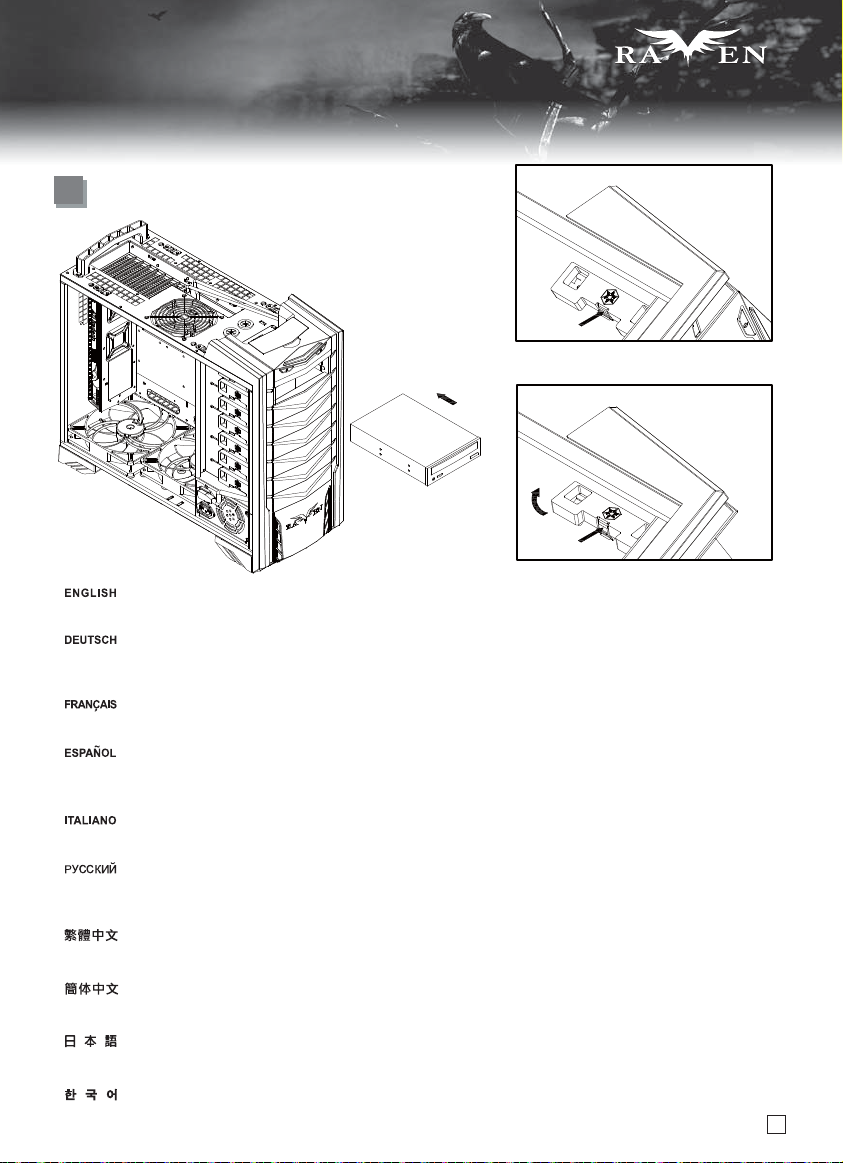
9
LOCK
UNLOCK
Push the 5.25” device into the drive bay and secure it by pushing the tool-less mechanism in the direction as shown to secure it.
Schieben Sie das 5,25 Zoll-Gerät in den 5,25 Zoll-Laufwerkschacht ein, fixieren Sie es, indem Sie die Mechanik in die angezeigte
Richtung schieben.
Poussez l'appareil 5,25” dans la baie 5,25” et fixez-le en poussant le mécanisme sans outils dans la direction montrée pour le fixer.
Empuje el dispositivo de 5,25” en la bahía para dispositivos de 5,25” y fíjelo empujando el mecanismo sin herramientas en la dirección
que se muestra para asegurarlo.
Spingere la periferica da 3,5” nel bay ed assicurarla mediante la pressione del meccanismo tool-less nella direzione mostrata in figura.
Вставьте устройство формата 5.25 дюйма в отсек 5.25 дюйма и закрепите устройство, надавив на механизм, не требующий
применения инструментов, в направлении, показанном на рисунке.
請先鬆開光碟機的Tooless將光碟機裝入機殼,再扣回tool-less。
请先松开光驱的Tooless将光驱装入机壳,再扣回tool-less。
5,25インチデバイスを5,25インチドライブベイに入れ、工具不要機構を押して固定します。
5,25” 디바이스를 5,25” 드라이브 베이로 밀어 넣은후, 그림에 나타난 방향으로 살짝 밀어 tool-less 메카니즘이
고정시키도록 합니다.
10
Page 12
SERIES
SERIES
lnstallation Guide
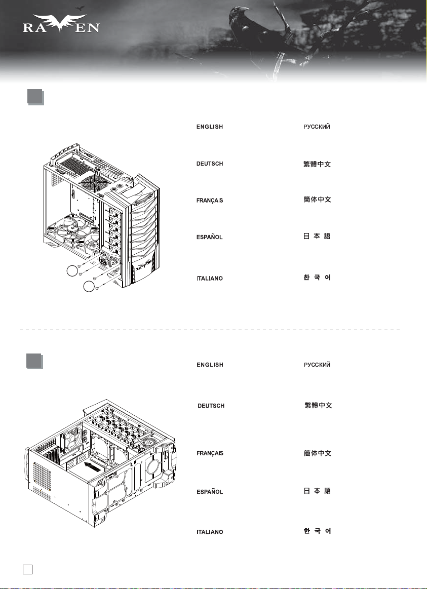
10
11
Loosen screws holding the 3.5” hard
drive brackets behind the motherboard
tray to remove them.
Lösen Sie die Schrauben der
Festplattenhalterungen von der
Rückseite des MotherboardEinschubs; entfernen Sie sie.
Desserrés les vis fixant les casiers
à disques durs derrière le support
de la carte mère pour les retirer.
Afloje los tornillos que sujetan
los brackets del disco duro tras
la bandeja de la placa base para
retirarlos.
Fissare l’alimentatore con le viti e
collegare il cavo di alimentazione
con il connettore a 90°.
Optionally, you can take this
opportunity to install screws on
the right side of optical drives if
extra security is needed.
Optional können Sie diese Gelegenheit
dazu nutzen, bei Bedarf zur zusätzlichen
Sicherheit Schrauben an der rechten
Seite der optischen Laufwerke zu
befestigen.
Отвинтите винты, крепящие
кронштейны жестких дисков,
за кронштейном материнской
платы и удалите кронштейны.
請鬆開背面3.5” 硬碟架的鎖固螺絲,
取下3.5” 硬碟架。
请松开背面3.5” 硬盘架的锁固螺丝,
取下3.5” 硬盘架。
ハードドライブブラケットを固定してい
るマザーボードトレイ裏側のネジを緩
めて、ブラケットを取り外します。
뒷면 3.5” 하드랙의 나사를 풀어준
후, 3.5” 하드랙을 꺼내십시오.
Кроме того, на этом этапе можно
установить винты с правой стороны
оптических приводов для их более
надежного закрепления.
如果您想要補上光碟機右方的螺絲,
可以在這個時候補上。
Facultativement, vous pouvez en
profiter pour installer des vis pour
fixer le côté droit des lecteurs
optiques si plus de sécurité est
requise.
De forma opcional puede aprovechar
esta oportunidad para instalar tornillos
en el lado derecho de los dispositivos
ópticos si necesita más seguridad.
Allentare le viti che tengono le staffe
11
degli hard drive per rimuoverli.
如果您想要补上光驱右方的螺丝,
可以在这个时候补上。
一つの選択肢として、より安全性を高め
るためにこの時点で光学ドライブの右側
にネジを取付けることもできます。
시디롬 드라이브의 우측 나사를
보충하고 싶을 경우, 이때
보충하십시오.
Page 13
lnstallation Guide
12
Insert hard drive into the hard drive
tray and then use screw B to secure it.
SERIES
SERIES
Вставьте жесткий диск в корзину
и закрепите его шурупом В.
13
Setzen Sie die Festplatte in den
Festplatteneinschub ein, fixieren
Sie die Festplatte mit der Schraube B.
Insérez un disque dur dans le support
puis utilisez des vis de type B pour
le fixer.
Inserte el disco duro en la bandeja
para discos duros y luego use el
tornillo B para fijarlo.
Inserire l’hard disk nel cestello quindi
usare le viti B per serrarlo.
Reinstall hard drive bracket back
into the case.
Bauen Sie die Festplattenhalterung
wieder in das Gehäuse ein.
Réinstallez le casier à disques durs
dans le boîtier.
Reinstale el bracket del disco duro
en la carcasa.
Reinstallare la staffa degli hard disk
nel case.
把硬碟放入硬碟架,
用SCREW B將其鎖固。
把硬盘放入硬盘架,
用SCREW B将其锁固。
ハードドライブをハードドライブトレイに
入れてから、ネジBで固定します。
하드 드라이브를 하드 드라이브
트레이에 삽입한 후, 나사 B를
이용해 고정시킵니다.
Вставьте кронштейн жесткого
диска обратно в корпус.
將3.5”硬碟架鎖回機殼。
将3.5”硬盘架锁回机壳。
ハードドライブブラケットをケー
スに戻します。
하드 드라이브 브라켓을 케이스에
재 설치합니다.
14
Loosen screws holding the 2.5” hard
drive brackets behind the motherboard
tray to remove them.
Lösen Sie die Schrauben der
Festplattenhalterungen von der
Rückseite des MotherboardEinschubs; entfernen Sie sie.
Desserrés les vis fixant les casiers à
disques durs derrière le support de la
carte mère pour les retirer.
Afloje los tornillos que sujetan los
brackets del disco duro tras la bandeja
de la placa base para retirarlos.
Allentare le viti che tengono le staffe
degli hard drive per rimuoverli.
Отвинтите винты, крепящие кронштейны
жестких дисков, за кронштейном
материнской платы и удалите кронштейны.
請鬆開背面2.5”硬碟架的鎖固螺絲,
取下2.5”硬碟架。
请松开背面2.5”硬盘架的锁固螺丝,
取下2.5”硬盘架。
ハードドライブブラケットを固定しているマ
ザーボードトレイ裏側のネジを緩めて、ブ
ラケットを取り外します。
뒷면 2.5” 하드랙의 나사를
풀어준 후, 2.5” 하드랙을
꺼내십시오.
12
Page 14
SERIES
SERIES
lnstallation Guide
15
2
1
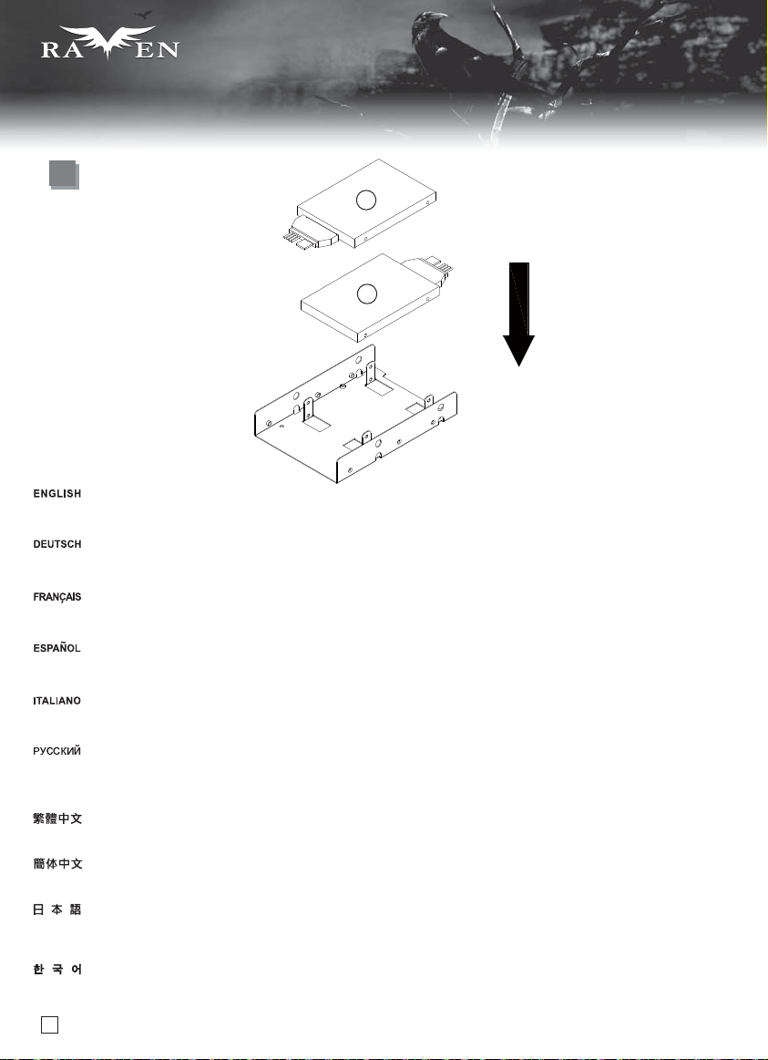
Insert a 2.5” hard drive or SSD into the 2.5” hard drive bracket. If you need to install two 2.5” SATA drives, please follow the direction shown in
the illustration, this will give you the most optimum position for cable management.
Stecken Sie eine 2,5 Zoll-Festplatte oder SSD in die 2,5 Zoll-Festplattenhalterung. Wenn Sie zwei 2,5 Zoll-SATA-Festplatten installieren müssen,
befolgen Sie bitte die in der Abbildung gezeigte Ausrichtung; dadurch erhalten Sie die optimale Position zur Kabelverwaltung.
Insérez un disque dur 2.5” ou un SSD dans l’emplacement pour disque dur 2.5”. Si vous avez besoin d’installer deux lecteurs SATA 2.5”, veuillez
suivre le sens montré sur l’illustration, ceci vous donnera la position optimale pour la gestion des câbles.
Inserte un disco duro de 2,5” ó SSD en el bracket para discos duros de 2,5”. Si necesita instalar dos dispositivos SATA de 2,5”, siga la dirección
que se muestra en la ilustración, eso le proporcionará la mejor posición para colocar los cables.
Inserire un hard drive da 2,5” o SSD nel supporto dedicato. Se avete bisogno di installare due drive sata da 2,5”, seguire il senso di montaggio
mostrato nell’illustrazione, questo vi darà il migliore posizionamento per la sistemazione dei cavi.
Установите 2,5-дюймовый жесткий диск или SSD-диск в кронштейн для 2,5-дюймового жесткого диска. При необходимости установки
двух 2,5-дюймовых SATA-дисков, соблюдайте направление, указанное на рисунке, что обеспечит оптимальное положение для
распределения кабелей.
請將2.5”硬碟依圖示放入2.5”硬碟架 ,如果您有需要安裝2顆2.5” SATA硬碟,請依照圖示的方向安裝,這有關於電源線材的最佳化配置。
请将2.5”硬盘依图标放入2.5”硬盘架 ,如果您有需要安装2颗2.5” SATA硬盘,请依照图标的方向安装,这有关于电源线材的最佳化配置。
2.5インチハードドライブブラケットに2.5インチハードドライブまたはSSDを入れます。2台の2.5インチSATAドライブをインストールする必要があるならば、
イラストで示された方向にインストールしてください。これがケーブル取り回しに最適な位置となります。
2.5” 하드는 그림대로 2.5” 하드랙에 넣으십시오. 2.5” SATA 드라이브를 설치하고 싶을 경우, 그림 방향대로 설치하십시오. 전원 와이어에
대한 최적화 배치입니다.
13
Page 15
lnstallation Guide
16
SERIES
SERIES
17
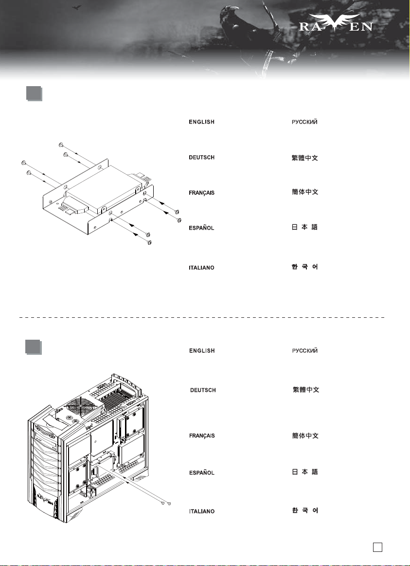
Use screw A to secure the 2.5” hard
drive to the bracket.
Sichern Sie die 2,5-Zoll-Festplatte
mit Schraube A an der Halterung.
Utilisez des vis A pour fixer le
disque dur 2.5” au casier.
Use el tornillo A para fijar el disco
duro de 2,5” al bracket.
Utilizzare le viti A per assicurare
la staffa al case.
Use screw A to secure the 2.5”
drive bracket to the case.
Sichern Sie die 2,5-ZollFestplattenhalterung
mit Schraube A am Gehäuse.
С помощью шурупа A прикрепите
2,5-дюймовый жесткий диск к
кронштейну.
請依圖示用SCREW A,將2.5”硬碟
鎖固於2.5”硬碟架。
请依图标用SCREW A,将2.5”硬盘
锁固于2.5”硬盘架。
2.5インチハードドライブをネジAでブラケ
ットに固定します。
나사 A를 이용해 2.5” 하드 드라이브를
브라켓에 고정시킵니다.
С помощью шурупа A прикрепите
кронштейн для 2,5-дюймового диска
к корпусу.
請依圖示用SCREW A,將2.5”硬碟架
鎖固於機身。
Utilisez des vis A pour fixer le
casier au boîtier.
Use el tornillo A para fijar el bracket
para dispositivos de 2,5” a la carcasa.
Utilizzare le viti A per assicurare la
staffa al case.
请依图标用SCREW A,将2.5”硬盘架
锁固于机身。
2.5インチハードドライブブラケットをネジ
Aでケースに固定します。
나사 A를 2.5”드라이브 브라켓을
케이스에 고정시킵니다.
14
Page 16
SERIES
SERIES
lnstallation Guide
18
19
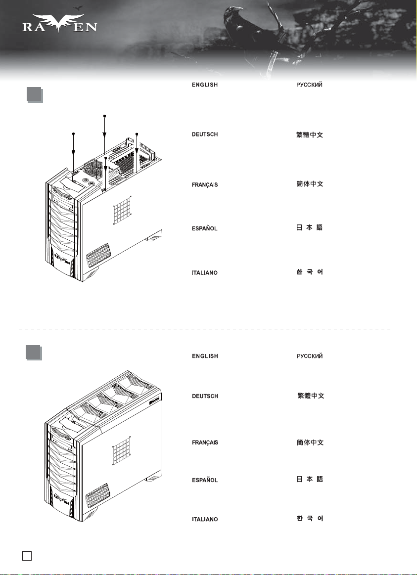
After all wires and cables are connected
and routed, place the side panels back
onto the case and secure with thumb
screws removed from step 2.
Nachdem alle Drähte und Kabel verlegt
und angeschlossen sind, befestigen Sie
die seitlichen Blenden wieder am
Gehäuse; sichern Sie die in Schritt 2
entfernten Flügelschrauben.
Après avoir branché tous les câbles,
remettez les panneaux latéraux sur le
boîtier et fixez-les avec des vis à main
retiré pendant l'étape 2.
Después de conectar y enrutar todos
los cables, vuelva a poner los paneles
laterales en la carcasa y fíjelos con los
tornillos que se quitaron en el paso 2.
Dopo che tutti i cavi sono stati connessi
e sistemati, rimontare il pannello laterale
sul case ed assicurarlo alla struttura
con le viti rimosse in precedenza
( al punto 2).
Place the top cover back onto the
case evenly to complete installation.
1После подключения всех проводов
и кабелей верните на место боковые
панели корпуса и закрепите винтами
с рифленой головк ой, открученными
на этапе 2.
接好所有需要接的線材之後,把左右
撤板裝回機殼,並以手扭螺絲鎖固。
接好所有需要接的线材之后,把左右
撤板装回机壳,并以手扭螺丝锁固。
すべてのリード線とケーブルが接続され、
取り回された後、ケースにサイドパネルを
戻し、ステップ2で外したつまみネジで固定
します。
모듯 선과 케이블이 연결되고, 정리가
된후, 사이드 패널을 케이스에 재
장착한 후, Step 2에서 본것과 같이
손나사로 사이드 패널을 고정시킵니다.
Установите на место верхнюю
крышку корпуса. Сборка завершена.
Zum Abschluss der Installation
bringen Sie die obere Abdeckung
wieder am Gehäuse an.
Remettez le panneau supérieur sur
le boîtier pour terminer l'installation.
Vuelva a poner la cubierta superior
en la carcasa de forma uniforme para
completar la instalación.
Riposizionare il top per completare
l’installazione.
15
將上蓋裝回機殼,完成組裝。
将上盖装回机壳,完成组装。
ケースに上部カバーを平らに戻すと、
インストール完了です。
상부 커버를 일정하게 힘을 가해
장착한 후 장착을 완료합니다.
Page 17
SERIES
SERIES
Connector definition
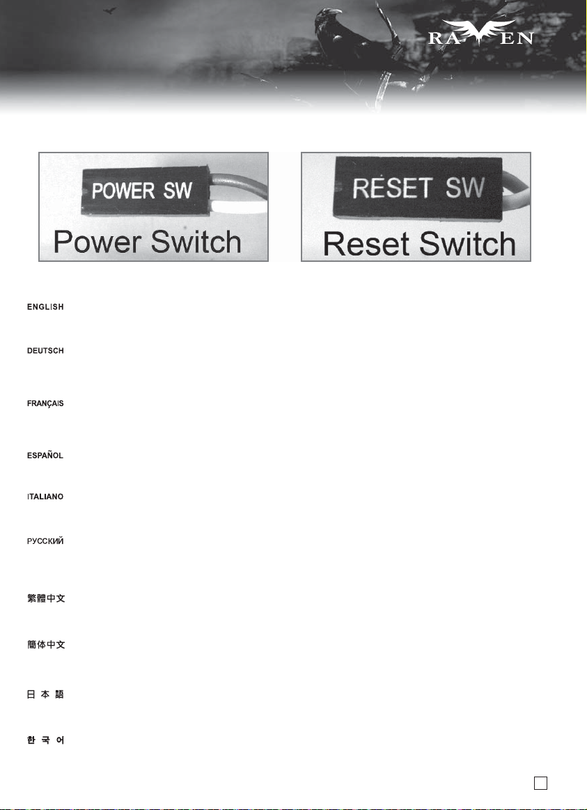
(1) Front panel connector installation
Power switch and reset switch installation guide:
Please refer to the motherboard manuals for the motherboard’s “Front Panel Connector” or “System Panel Connector” pin definition.
Power switch and reset switch have no polarity, so they can be connected in any orientation.
Bitte suchen Sie in der Motherboard-Dokumentation nach der Pinbelegung der Anschlüsse des Frontbedienfeldes („Front Panel Connectors“
oder „ System Panel Connectors“). Ein-/Austaste und Rücksetztaste benötigen keine bestimmte Polarität, können daher beliebig (ohne auf +
und - zu achten) angeschlossen werden.
Veuillez-vous référer au manuel de votre carte mère pour la description des broches "des connecteurs du panneau frontal" et des broches
"des connecteurs du panneau système". Les interrupteurs d'allumage et de réinitialisation ne possède pas de polarité, donc ils peuvent être
branché dans les deux sens.
Por favor, consulte en los manuales de la placa base la configuración de pines del “Conector de panel frontal” ó “Conector de panel de sistema”
de su placa base. Los interruptores de encendido y reseteo no tienen polaridad, luego se pueden conectar con cualquier orientación.
Fare riferimento al manuale della scheda madre nella sezione “Connettori del pannello frontale” o “Connettori del pannello di sistema”. Power
switch e reset switch non hanno polarità, posso essere pertanto connessi con qualsiasi orientamento.
Описание контактов разъемов приведены в разделах “Разъемы передней панели” или “Разъемы системной панели” руководства
пользователя материнской платы. Выключатель питания и кнопка перезагрузки не имеют полярности, поэтому их можно подключать
в любой ориентации.
請參考主機說明書的Front Panel Connectors安裝Pin Define,將Connector插上;Power Switch 與Reset Switch並無正負極性之分,
反插正插都不影響功能性。
请参考主机说明书的Front Panel Connectors安装Pin Define,将Connector插上;Power Switch 与Reset Switch并无正负极性之分,
反插正插都不影响功能性。
マザーボードの「フロントパネルコネクタ」または「システムパネルコネクタ」のピン配列についてはマザーボードマニュアルを参照してください。
電源スイッチとリセットスイッチに極性はないので、いずれの方向でも接続できま。
메인보드 매뉴얼의 전면패널 커넥터 혹은 시스템패널 커넥터 핀을 참조하기 바랍니다. 파워 스위치와 리셋 스위치는 극성이 없어 어떤
방향으로 설치해도 무방합니다.
16
Page 18
SERIES
SERIES
Connector definition
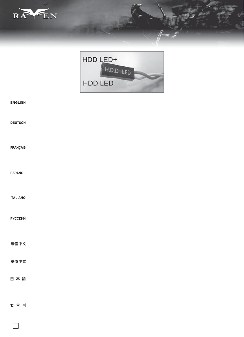
LED connector installation guide:
Please refer to the motherboard manuals for the motherboard’s “Front Panel Connector” or “System Panel Connector” pin definition.;the white
wires are negative while other colors are positive wires. The Power LED wires are separate pins for compatibility with different motherboard pin
definition so please make sure they are connected in the right polarity by referring to your motherboard manual.
LED-Verbinder installieren: Bitte suchen Sie in der Motherboard-Dokumentation nach der Pinbelegung der Anschlüsse des Frontbedienfeldes
(„Front Panel Connectors“ oder „System Panel Connectors“). Die weißen Adern sind negativ (-), die farbigen Adern positiv (+).Die Kabel für die
Betriebsanzeige-LED sind zur Kompatibilität mit unterschiedlichsten Motherboards einzeln, nicht als kompletter Stecker ausgeführt. Achten Sie
hier bitte auf die richtige Polarität, lesen Sie in der Dokumentation Ihres Motherboards nach.
Veuillez-vous référer au manuel de votre carte mère pour la description des broches "des connecteurs du panneau frontal" et des broches "des
connecteurs du panneau système". Les câbles colorés en blanc sont négatifs alors que ceux d'une autre couleur sont positifs.Les câbles de la
LED Power sont séparés afin d'être compatible avec différentes cartes mères, donc vérifiez bien qu'ils sont branchés avec la bonne polarité en
vous référant au manuel de votre carte mère.
Por favor, consulte en los manuales de la placa base la configuración de pines del “Conector de panel frontal” ó “Conector de panel de sistema”
de su placa base. Los cables de color blanco son negativos mientras que los de color son positivos. Los cables LED de potencia tienen pines
separados para compatibilidad con diferentes definiciones de pines de la placa base luego por favor, asegúrese de que están conectados en la
polaridad correcta consultando el manual de su placa base.
Fare riferimento al manuale della scheda madre nella sezione “Connettori del pannello frontale” o “Connettori del pannello di sistema”. I cavi
di colore bianco sono il polo negativo, mentre quelli di colore diverso il positivo.Guida all’installazione del Power Led serie RV/KLConnettere
direttamente il connettore ad un molex dell’alimentatore
Описание контактов разъемов приведены в разделах “Разъемы передней панели” или “Разъемы системной панели” руководства
пользователя материнской платы. Белые провода - отрицательной полярности, цветные провода - положительной полярности.
Провода светодиодного индикатора питания имеют отдельные контакты для совместимости
материнских плат, поэтому обратитесь к руководству пользователя материнской платы и убедитесь, что полярность соблюдена.
請參考說明書的Front Panel Connectors安裝Pin Define,將Connector插上;白色線的部分為負極,彩色線的部分是正極。
Power LED為了適應各主機板的不同,特別設計為散Pin樣式,請安心使用。
请参考说明书的Front Panel Connectors安装Pin Define,将Connector插上;白色线的部份为负极,彩色线的部份为正极。
Power LED为了适应主机板的不同,特别设计为散Pin样式,请安心使用。
LEDコネクタのインストールガイド:
マザーボードの「フロントパネルコネクタ」または「システムパネルコネクタ」ピン配列についてはマザーボードマニュアルを参照してください。
白色のリード線はマイナスで、色の着いたリード線がプラスです。電源LEDリード線は種々のマザーボードピン定義と互換性を持たせるため
分離されたピンとなっているので、ご使用のマザーボードマニュアルを参照して、 適切な極性に接続されるようお確かめください。
메인보드 매뉴얼의 전면패널 커넥터 혹은 시스템패널 커넥터 핀을 참조하기 바랍니다. 하얀선의 경우 음극이며, 다른 색의 경우
양극입니다. 파워 LED 선은 분리되어 다양한 메인보드에서 동작할 수 있도록 되어 있습니다. 그러므로 메인보드 매뉴얼을 참조하여
올바를 극성을 주의해 선택하시기 바랍니다.
17
с различными типами контактов
Page 19

SERIES
SERIES
Front I/O connector guide
Below are the front I/O connectors pin definition, please also check your motherboard manual to cross reference with motherboard’s
front I/O pin headers. SilverStone’s I/O connectors are in block type to simplify installation.
Nachstehend finden Sie die Pinbelegung der vorderen E/A-Anschlüsse; bitte gleichen Sie zudem das Handbuch Ihres Motherboards mit
den vorderen E/A-Pinzuweisungen ab. SilverStones E/A-Anschlüsse befinden sich zur Vereinfachung der Installation in Blockart.
Au dessous de la description des broches des ports d'E/S, veuillez aussi vérifier sur le manuel de votre carte mère de manière croisée
que les broches sont correctement placées. Les connecteurs d'E/S de SilverStone sont en bloc pour en simplifier leur installation.
A continuación tiene la definición de pines de los conectores frontales de E/S, también debe consultar el manual de su placa base para c
omprobar la referencia de los pines para E/S frontales. Los conectores de E/S de SilverStone son de bloque para simplificar la instalación.
Di seguito lo schema delle connessioni I/O frontali, confrontare lo schema con quanto riportato sul manuale della scheda madre per
effettuare una controllo incrociato. I connettori I/O Silverstone, per semplificare l’installazione, sono del tipo “a blocco”.
Ниже приведено описание контактов передних разъемов ввода/вывода. Обратитесь также к руководству пользователя материнской
платы за описанием передних разъемов ввода/вывода типа "пин-хедер". Разъемы ввода/вывода "SilverStone" - блочного типа, что
облегчает сборку.
下表為Front I/O Connectors的Pin Define,請參閱主機板說明書的各Front I/O Connectors Pin Define一一核對。
RV03的Front I/O Connectors完全採用集合Pin方式以簡化安裝。
下表为Front I/O Connectors的Pin Define,请参阅主机板说明书的各Front I/O Connectors Pin Define一一核对。
RV03的Front I/O Connectors完全采用集合Pin方式以简化安装。
以下はフロントI/Oコネクタピン配列ですが、お持ちのマザーボードのフロントI/Oピンヘッダは、マザーボードマニュアルをご参照ください。
シルバーストーンのI/Oコネクタは、インストールの容易なブロックタイプになっています。
아래는 전면 I/O 커넥터의 핀 설정이며, 메인보드 매뉴얼을 참조해 메인보드의 전면 I/O 핀 헤더와 맞추어 설치합니다.
Silverstone의 I/O 커낵터는 블록 타이브로 구성되어 설치를 간편화 했습니다.
18
Page 20

SERIES
SERIES
Component size limitations
The RAVEN RV03 was designed to accommodate oversize components,
but we still recommend to refer to the following dimension guidelines:
(1) CPU cooler height limitation
Maximum CPU cooler height is 163mm and the clearance at the edge of motherboard is 25.4mm (from motherboard top edge to 5.25” bracket).
If you need to install extra long optical drive and is unsure whether there are clearance issues with your choice of CPU cooler, please refer to the
optical drive limitation illustration.
Die maximale Höhe des CPU-Kühlers beträgt 163 mm; der Freiraum an der Kante des Motherboards misst 25,4 mm (von der oberen Kante des Motherboards
bis zur 5,25 Zoll-Halterung). Wenn Sie ein überlanges optisches Laufwerk installieren müssen und nicht sicher sind, ob Platzprobleme aufgrund des von
Ihnen ausgewählten CPU-Kühlers auftreten, beachten Sie bitte die Abbildung zur Beschränkung des optischen Laufwerks.
La hauteur maximale du dissipateur de processeur est de 163mm et l'espace jusqu'au bord de la carte mère est de 25.4mm (du bord supérieur de la carte
mère jusqu'au casier 5.25”). Si vous avez besoin d'installer un lecteur optique et que vous doutez sur l'espace disponible pour le faire à cause de votre choix
de dissipateur, veuillez-vous référer à l'illustration des limitations des lecteurs optique.
La altura máxima del disipador de la CPU es de 163mm y el espacio libre alrededor de la placa base es de 25,4mm (desde el extremo superior de la placa
base hasta el bracket de 5,25”). Si necesita instalar un dispositivo óptico extra largo y no está seguro del espacio libre por su elección del disipador de la CPU,
consulte por favor la ilustración para la limitación del dispositivo óptico.
La massima altezza consentita per il dissipatore della CPU è di 163mm e la spaziatura ai bordi della scheda madre è di 25,4mm (dall’angolo alto fino allo
slot da 5,25”). Se avete bisogno di installare drive ottici più lunghi del normale, considerate le limitazioni esposte, onde evitare interferenze tra il drive ottico
e il dissipatore della CPU. Fate anche riferimento all’illustrazione relativa alle limitazioni di misura per il drive ottico.
Высота процессорного кулера не должна превышать 163 мм, а зазор у края материнской платы должен составлять 25,4 мм (от верхнего края
материнской платы до кронштейна для 5,25-дюймового привода). Если необходимо установить очень длинный оптический привод, но вы не
уверены, будет ли достаточным зазор
оптического привода.
между ним и выбранным процессорным кулером, см. рисунок, иллюстрирующий ограничения на размер
Cooler限高是163mm,Cooler外源允許超出主機板上邊界25.4mm(以光碟機折邊算起)如果您需要安裝超長的光碟機,不確定是否與Cooler干涉,
請參考光碟機限制的圖面來評估。
Cooler限高是163mm,Cooler外源允许超出主机板上边界25.4mm(以光驱折边算起)如果您需要安装超长的光驱,不确定是否与Cooler干涉,
请参考光驱限制的图面来评估。
最大のCPUクーラー高さは163mmであり、マザーボード縁からの間隙は25.4mm(マザーボード上端から5.25インチブラケットまでの距離)です。特別に長い光学ドラ
イブをインストールする必要があり、CPUクーラーの選択で設置間隔に問題がないかどうか不明な場合は、光学ドライブの限度説明をご参照ください。
Cooler 높이는 163mm까지이고, Cooler 외측은 메인보드 경계 25.4mm까지 초과될 수 있습니다.(시디롬 드라이브 플랩으로 계산)매우 긴 시디롬
드라이브를 설치해야 할 경우, Cooler 와 간섭 문제에 대해서는, 시디롬 드라이브 제한 도면을 참고하시기 바랍니다.
Motherboard
Cooler
25.4
SIDE PANEL
cooler
163
Motherboard
19
CPU cooler hight limitation 163mm CPU cooler exceed Motherboard limitation 25.4mm
Page 21

SERIES
SERIES
Component size limitations
(2) Power supply length limitation
A: Depth limitation
TheRV03 supports power supply with depth of up to 180mm. We use a specific extension cord for connecting to power supply’s AC plug,
so it does not support large, specialized plug found in extremely high wattage power supplies (e.g. SilverStone ST1500). If high wattage
power supply is required, we recommend the Strider Gold ST1200-G, which conforms to RV03’s dimension and extension power cord
requirements.
B: Cable length recommendations
Below is a table of recommend cable length based off of common retail power supplies. Please make sure that the power supply you want
to use has long enough cables to fit the below recommendations or you can also choose to purchase additional power cable extensions.
A: Beschränkung der Netzteiltiefe
Das RV03 unterstützt Netzteile mit einer Tiefe von bis zu 180 mm. Wir verwenden ein spezifisches Verlängerungkabel zum Anschließen
am AC-Netzteilstecker; daher werden keine großen, spezialisierten Stecker unterstützt, die bei Netzteilen mit sehr hoher Wattzahl (z. B.
dem SilverStone ST1500) verbaut sind. Falls Sie ein Netzteil mit hoher Wattzahl benötigen, empfehlen wir das Strider Gold ST1200-G;
dieses stimmt mit den Abmessungen des RV03 sowie den Anforderungen an das Verlängerungsnetzkabel überein.
B: Empfohlene Kabellänge
Nachstehend finden Sie eine Tabelle der empfohlenen Kabellänge basierend auf handelsüblichen Netzteilen. Bitte stellen Sie sicher, dass
das von Ihnen gewählte Netzteil entsprechend der nachstehenden Empfehlungen über ausreichend lange Kabel verfügt; alternativ können
Sie zusätzliche Netzkabelverlängerungen kaufen.
A: Limitation en profondeur
Le FT03 est compatible avec les alimentations d'une profondeur inférieure ou égale à 180mm. Nous utilisons une rallonge spécifique
pour brancher l'alimentation à la prise secteur, donc il n'est pas compatible avec les cordons plus grand, les connecteurs spécialisés
trouvés dans les alimentations très puissantes (par ex: SilverStone ST1500). Si une alimentation à très forte puissance est nécessaire,
nous vous recommandons la Strider Gold ST1200-G, qui est compatible avec les contraintes du RV03, à savoir les dimensions et le cordon
d'alimentation.
B: Longueur des câbles
Vous avez ci dessous un tableau avec la longueur des câbles recommandés basé sur les alimentations du marché. Veuillez bien vérifier
que l'alimentation que vous allez utiliser possède bien des câbles assez long pour être compatible avec ces recommandations. Sinon vous
pouvez choisir d'acheter des rallonges.
A: Limitación de profundidad de la FA
La RV03 acepta fuentes de alimentación con una profundidad de hasta 180mm. Ya que usamos un cable de extensión específico para
conectar el enchufe AC de la fuente de alimentación, no se pueden usar los enchufes grandes y especializados que se encuentran en
las fuentes de alimentación de alta potencia (como la Silverstone ST1500). Si necesita una fuente de alimentación de alta potencia, le
recomendamos la Strider Gold ST1200-G, que se adapta a las dimensiones de la RV03 y los requisitos del cable de potencia.
B: Recomendación de la longitud de los cables de la FA
A continuación hay una tabla con la longitud recomendada de los cables basada en fuentes de alimentación comunes. Por favor, asegúrese
de que la fuente de alimentación que quiere usar tiene cables lo bastante largos como para adecuarse a las recomendaciones siguientes, en
caso contrario puede decidir comprar extensiones adicionales para cables de potencia.
A: Limitazioni profondità PSU
RV03 supporta alimentatori con profondità fino a 180mm. Utilizziamo un cavo specifico per connettere l’alimentazione al plug AC, quindi non
sono supportati i plug specifici utilizzati negli alimentatori ad elevato wattaggio (come ad esempio il SilverStone ST1500). Se avete bisogno di
un alimentatore ad elevata potenza vi raccomandiamo il modello Strider Gold ST1200-G, che si adatta alle dimensioni ed al formato del cavo
di alimentazione.
B: Raccomandazioni sulla lunghezza dei cavi della PSU
La tabella di seguito mostra le lunghezze dei cavi raccomandate e si basa sulle misure dei cavi con riferimento ai comuni alimentatori retail.
Assicuratevi che l’alimentatore che avete intenzione di utilizzare risponda alle caratteristiche richieste, altrimenti considerate l’acquisto di un
kit di prolunga cavi.
20
Page 22

SERIES
SERIES
Component size limitations
A: Ограничение по глубине
Корпус RV03 допускает установку блока питания глубиной до 180 мм. Мы используем специальный удлинительный кабель,
подсоединяемый к розетке переменного тока блока питания, поэтому невозможно использовать особую большую розетку,
которая имеется на блоках питания сверхвысокой мощности (например, SilverStone ST1500). Если требуется установить блок
питания высокой мощности, рекомендуется использовать блок питания Strider Gold ST1200-G, соответствующий размерам
RV03 и допускающий подключение удлинительного кабеля питания.
корпуса
B: рекомендации по длине кабелей
В следующей таблице представлены рекомендованные значения длины кабелей на основе значений имеющихся в продаже
источников питания. Убедитесь, что длина кабелей источника питания достаточна и соответствует следующим рекомендациям,
в противном случае можно приобрести дополнительные удлинители кабеля источника питания.
A: 長度限制:
RV03的PSU可用總空間有180mm, 無論如何,我們最推薦使用Strider Plus系列電源,而RV03因為內部採用電源延長接頭,
所以不支援需要大方型電源接頭的電源供應器(例如ST1500), 如果需要最高瓦數的電源,建議使用SST-ST1200-G金牌1200W電源。
B: 電源線材建議長度:
以下是以一般市售ATX 主機板抓出來的各線材建議長度列表,請先確認電源線長度是否足夠,如果不夠請選購所需要的延長線。
A: 长度限制:
RV03的PSU可用总空间有180mm, 无论如何,我们最推荐使用Strider Plus系列电源,而RV03因为内部采用电源延长接头,
所以不支持需要大方型电源接头的电源供应器(例如ST1500), 如果需要最高瓦数的电源,建议使用SST-ST1200-G金牌1200W电源。
B: 电源线材建议长度:
以下是以一般市售ATX 主机板抓出来的各线材建议长度列表,请先确认电源线长度是否足够。
A: 奥行き制限
RV03は最高180mmの奥行きの電源をサポートします。電源のACプラグと接続するのに専用延長コードを使うので、極めて高いワット数電源
(例: SilverStone ST1500)に見られる大型で専用のプラグはサポートしません。高ワット数の電源が必要とされる場合、RV03のサイズと延長
電源コード必要条件に対応しているStrider Gold ST1200-Gを推奨します。
B: 推奨ケーブル長さ
下記は、一般の小売り電源の推奨ケーブル長さの表です。使いたい電源が下記の推奨基準に合った、十分の長さのケーブルを持っていること
を確認してください。または電源用の延長ケーブルを購入することもできます。
A: 깊이의 제약.
RV03은 180mm의 깊이를 갖는 파워 서플라이까지 지원합니다. AC전원과 파워 서플라이를 연결하는 특수한 연장 케이블을 사용하기
때문에, 용량이 큰 파워 서플라이
꼭 사용해야 한다면, RV03의 규격과 확장 케이블 규격을 지원하는 Gold ST1200-G 사용을 권장합니다.
B: 추천 케이블 길이
아래 표에서는 일반적으로 판매되는 파워 서플라이의 추천 케이블 길이를 표시해 놓았습니다. 사용하고자 하는 파워 서플라이가 아래의
추천길에에 충분한 케이블을 갖추고 있는지 확인하시기 바라며, 필요시에는 추가의 연장 파워 케이블 구입이 가능합니다.
SIDE PANEL
RIGHT
21
Power supply length limitation 180mm
(예. SilverStone ST1500) 에서 사용하는 큰 플러그를 지원하지 않습니다. 고용량의 파워 서플라이를
Motherboard
180
SIDE PANEL
LEFT
Cable type and location
EPS 8pin/ATX4pin
ATX 24Pin
SATA 15pin to first 5.25” slot
Behind the motherboard tray, for the two 3.5”
drives near the front of the case to middle 2.5”
drive facing forward
Behind the motherboard tray, for the two 3.5”
drives near the rear of the case to middle 2.5”
drive facing rearward
PCI-E 8/6pin to card installed in the seventh
expansion slot
Minimum length
400mm
400mm
350mm
150mm to 2.5” SATA drive,
then 150mm each after
250mm to 2.5” SATA drive,
then 150mm each after
400mm
Page 23

Component size limitations
(3) Graphic card/expansion card length limitation
RV03 can support 13.58” consumer level graphics cards.
Graphic card length reference:
AMD Radeon HD 5970 – 12.2 "
AMD Radeon HD 6970 – 11”
AMD Radeon HD 6950 – 11”
AMD Radeon HD 5870 – 11”
AMD Radeon HD 6870 – 10.5”
NVidia Geforce GTX580 – 10.5”
NVidia Geforce GTX480 – 10.5”
AMD Radeon HD 5850 – 9.5””
NVidia Geforce GTX470 – 9.5”
AMD Radeon HD 6850 – 9”
(4) Motherboard size limitation
RV03 supports Extended ATX motherboard
SERIES
SERIES
New generation of SSI-EEB server or workstation motherboards no longer require CPU cooler mounting holes on the motherboard tray.
Coolers can now be installed directly on the motherboard. As a result, we eliminated support for SSI-EEB CPU cooler mounting holes
and instead increased the large gap on the motherboard tray to support CPU cooler back plates swapping with more LGA 1156/1155
motherboards. RV03’s support for new and future SSI-EEB motherboards should be unaffected by this change.
Hochmoderne Motherboards von SSI-EEB-Servern und -Arbeitsrechnern benötigen keine Löcher zur CPU-Kühlermontage am
Motherboard-Einschub mehr. Die Kühler können nun direkt am Motherboard installiert werden. Dadurch haben wir die Unterstützung
der Löcher zur SSI-EEB-CPU-Kühlermontage aufgegeben und stattdessen den Abstand am Motherboard-Einschub vergrößert; dadurch
werden CPU-Kühlerrückplatten unterstützt, die mit einer größeren Anzahl an LGA 1156-/1155-Motherboards kompatibel sind. Die
Unterstützung neuer und zukünftiger SSI-EEB-Motherboards durch das RV03-Gehäuse wird durch diese Änderung nicht beeinflusst.
22
Page 24

SERIES
SERIES
Component size limitations
La nouvelle génération de cartes mère de serveur SSI-EEB ou de station de travail ne nécessitent plus de trou de montage sur le support de la
carte mère. Les dissipateurs peuvent désormais être installés directement sur la carte mère. Nous en avons profité pour supprimé la compatibilité
avec les trous de montage des dissipateurs pour les processeurs SSI-EEB et nous avons à la place élargi l'espace du support de la carte mère
pour faciliter le démontage des plaques arrières des dissipateurs de processeurs avec plus de carte mère LGA 1156/1155. La compatibilité du
RV03 avec les nouvelles cartes mères SSI-EEB ne devraient pas être impactées par ce changement.
La nueva generación de placas base SSI-EEB para servidores ó estaciones de trabajo ya no precisan de agujeros de montaje para el disipador
de la CPU en la bandeja de la placa base. Es por esto que hemos eliminado la compatibilidad para los agujeros de montaje SSI-EEB para el
disipador de la CPU y en cambio hemos incrementado el espacio en la bandeja de la placa base para poder instalar placas traseras disipadoras
de la CPU con más placas base LGA 1156/1155. La compatibilidad presente y futura de la RV03 con las placas base SSI-EEB no debería verse
afectada por este cambio.
La nuova generazione di schede madri per server o workstation SSI-EEB non richiedono più la presenza di fori per il montaggio del dissipatore
CPU sul supporto scheda madre. I coolers possono essere assemblati direttamente sulla motherboard. A questo proposito, abbiamo eliminato i
fori di montaggio dal supporto scheda madre aumentando invece le dimensioni dell’apertura praticata sul tray, in modo da massimizzare la
compatibilità con eventuali cambi di mainboard. Il supporto quindi per le presenti e future schede madri in formato SSI-EEB è comunque garantito.
Материнским платам форм-фактора SSI-EEB нового поколения для серверов и рабочих станций больше не требуются монтажные
отверстия для процессорного кулера на кронштейне материнской платы. Теперь кулеры можно устанавливать непосредственно на
материнскую плату. Поэтому в корпусе теперь отсутствуют монтажные отверстия под процессорный кулер для материнских плат
форм-фактора SSI-EEB и увеличен зазор на кронштейне материнской платы для поддержки крепежных пластин процессорного
кулера, которыми теперь оснащается все больше материнских плат с разъемом LGA 1156/1155. Это изменение не должно повлиять
на совместимость корпуса RV03 с новыми и будущими моделями материнских плат форм-фактора SSI-EEB.
新一代SSI-EEB規格伺服器主機板,已經沒有利用SSI規範的Xeon Cooler在機殼上的鎖固孔位。而Cooler本身是所在主機板上。我們新一代的機殼
為了配合LGA1156的位置,而把MB底板對應的開孔加大,因而取消了SSI規範上的Cooler鎖固螺柱。並不是不相容於SSI EEB主機板;只是因應主
機板規格的演進而修改設計。
新一代SSI-EEB规格服务器主机板,已经没有利用SSI规范的Xeon Cooler在机壳上的锁固孔位。而Cooler本身是所在主机板上。我们新一代的机壳
为了配合LGA1156的位置,而把MB底板对应的开孔加大,因而取消了SSI规范上的Cooler锁固螺柱。并不是不兼容于SSI EEB主机板;只是因应主
机板规格的演进而修改设计。
新世代のSSI-EEBサーバまたはワークステーションのマザーボードは、もはやマザーボードトレイ上にCPUクーラー取り付け穴を必要としていません。クー
ラーは現在直接マザーボードにインストールできます。結果として、SSI-EEB CPUクーラー取り付け穴への対応をやめ、代わりに、より多くのLGA1156/1155
マザーボードと互換性のあるCPUクーラー後部プレートをサポートするよう、マザーボードトレイ上の大きな間隙を増大させました。新たな、また将来のSSI-
EEBマザーボードへのRV03のサポートはこの変化の影響は受けません。
신세대 SSI-EEB 규격 서버 메인보드는 이미 SSI 규범의 Xeon Cooler를 케이스상의 잠금 구멍에 사용하지 않으며, Cooler 자체가 메인보드 위에
위치해 있습니다. 신세대 케이스는 LGA1156 위치에 따라, MB 바닥면에 대응하는 구멍을 확대시킴으로써, SSI 규범상의 Cooler 잠금 나사를
없앴습니다. SSI-EEB 메인보드와 호환되지 않는 것이 아니라, 메인보드 규격의 발전에 따라 수정 설계된 것입니다.
23
Page 25

SERIES
SERIES
Component size limitations
Please note that some server motherboards may have a few more
non-standardized motherboard mounting holes. RV03 will only have
standardized holes that should provide adequate mounting without
the use of non-standardized holes.
Помните, что некоторые материнские платы для серверов
могут иметь несколько дополнительных нестандартных
монтажных отверстий. Корпус RV03 оснащен только
стандартными отверстиями, обеспечивающими достаточное
крепление без использования нестандартных отверстий.
Bitte beachten Sie, dass einige Server-Motherboards über zusätzliche,
nicht-standardmäßige Motherboard-Montagelöcher verfügen können.
RV03 ist nur mit standardisierten Löchern ausgestattet, die ohne
Nutzung der nicht-standardmäßigen Löcher eine angemessene Montage
ermöglichen.
Veuillez noter que certaines cartes mère de serveur peuvent avoir
quelques trous de montage non standardisés. Le RV03 possède
seulement des trous de montage qui permettent un montage adéquat
sans l'utilisation de trous non standardisés.
Por favor, tenga en cuenta que algunas placas base para servidores
podrían tener agujeros de montaje que no cumplan el estándar.
La RV03 tendrá sólo agujeros estándar que deberían proporcionar
un montaje adecuado sin el uso de agujeros no estándar.
Alcune schede madri per server possono avere fori di montaggio
aggiuntivi non standard. RV03 ha solo fori standard, ma questo non
dovrebbe inficiare il alcun modo il montaggio di tali mainboard.
要注意的是,許多Server主機板可能會有多增加一些非標準的鎖固孔位。
RV03只會有規範上應該有的鎖固孔位。
要注意的是,许多Server主机板可能会有多增加一些非标准的锁固孔位。
RV03只会有规范上应该有的锁固孔位。
サーバ用マザーボードによってはいくらかの規格化されていないマザーボ
ード取り付け穴を持っている場合があることにご注意ください。
RV03は、規格化されていない穴を使用せずに適正な取り付けの可能な標準
の穴のみを装備しています。
주의해야 할 점은 많은 Server 메인보드에 비표준의 잠금 구멍이 더
있을 수 있다는 점입니다. RV03에는 규범상 있어야 할 잠금 구멍만
있습니다.
24
Page 26

SERIES
SERIES
Component size limitations
All cables must pass through here when
Extended ATX motherboard is installed.
There is no extra clearance between the 180mm fans and edge of a SSI EEB motherboard so it may be difficult to route power supply cables to the front
from behind the motherboard tray. If you are using a 13” wide motherboard, we recommend replacing the two included 180mm fans with three standard
thickness 120mm fans.
Es besteht kein zusätzlicher Freiraum zwischen den 180 mm-Lüftern und der Kante eines SSI-EEB-Motherboards, sodass es schwierig sein kann, die
Netzteilkabel von der Rückseite des Motherboards-Einschubs zur Vorderseite zu führen. Wenn Sie ein 13 Zoll breites Motherboard nutzen, empfehlen
wir, die beiden mitgelieferten 180 mm-Lüfter durch drei Lüfter mit einer Standarddicke von 120 mm zu ersetzen.
Il n'y a pas d'espace supplémentaire entre les ventilateur de 180mm et le bord d'une carte mère SSI EEB donc il peut s'avérer difficile de faire passer les
câbles d'alimentation vers l'avant derrière le support de la carte mère. Si vous utiliser une carte mère de 13”, nous vous recommandons de remplacer les
deux ventilateurs inclus par trois ventilateur de 120mm d'épaisseur standard.
No existe un espacio libre necesario adicional entre los ventiladores de 180mm y el borde de una placa base SSI EEB, luego podría ser complicado enrutar
los cables de la fuente de alimentación desde la parte frontal hasta la parte trasera de la bandeja de la placa base. Si está usando una placa base de 13” de
ancho, le recomendamos reemplazar los dos ventiladores incluidos de 180mm con tres ventiladores de un grosor estándar de 120mm.
Non c’è tolleranza tra le ventole da 180mm ed il bordo di una scheda madre SSI EEB per cui è difficoltosa la sistemazione dei cavi dalla parte frontale alla
posteriore del supporto scheda madre. Se usate quindi una scheda madre larga 13” (33,02cm) vi raccomandiamo di sostituire le due ventole da 180mm
con tre 120mm di spessore standard.
Между 180-мм вентиляторами и краем материнской платы форм-фактора SSI EEB отсутствует дополнительный зазор, поэтому может быть трудно
проложить кабели блока питания из-за материнской платы к передней панели. В случае использования материнской платы шириной 13 дюймов
рекомендуется заменить два
另外180mm風扇與SSI-EEB規格主機板之間並沒有保留太多距離,背面的電源線要拉到正面來會比較困難。如果使用長度達13”的主機板,建議將兩顆180mm
風扇降級為3顆120mm規格風扇。
另外180mm风扇与SSI-EEB规格主机板之间并没有保留太多距离,背面的电源线要拉到正面来会比较困难。如果使用长度达13”的主机板,建议将两颗180mm
风扇降级为3颗120mm规格风扇。
180mmファンとSSI-EEBマザーボードの縁の間に隙間が全然ないのでマザーボードトレイの後ろから正面に電源ケーブルを取り回すのが難しい場合があります。
13インチ幅のマザーボードが使用されている場合、同梱の180mmファン2台を標準厚さの120mmファン3台と交換するようお勧めいたします。
그밖에 180mm 팬과 SSI-EEB 규격의 메인보드 사이에는 큰 거리를 남겨두지 않았으며, 뒷면 전원선을 정면으로 끌어오는게 비교적 어렵습니다.
만약 13”길이의 메인보드를 사용한다면, 180mm 팬 두개를 120mm 팬 3개 규격으로 사용하십시오.
входящих в комплект поставки 180-мм вентилятора тремя 120-мм вентиляторами стандартной толщины.
25
Page 27

Component size limitations
(5) Optical drive depth limitation
SERIES
SERIES
Optical drive Depth Limitation 220mm
The distance is 220mm from RV03’s front bezel to the edge
of the motherboard.
Der Abstand zwischen der Frontblende des RV03 und der Kante
des Motherboards beträgt 220 mm.
10mm
Расстояние 220 мм от лицевой панели корпуса RV03 до края
материнской платы.
RV03從光碟機表面,到主機板邊的距離有220mm。
205mm
220mm
La distance entre la façade du RV03 et le bord de la carte mère
est de 220mm.
La distancia es 220mm desde el panel frontal de la RV03 hasta
el borde de la placa base.
La distanza tra il bordo della scheda madre ed il frontale del
case è di 220mm.
RV03从光驱表面,到主机板边的距离有220mm。
距離はRV03のフロントベゼルからマザーボード縁までの220mmです。
RV03은 시디롬 드라이브 표면으로부터 메인보드까지 거리는
220mm입니다.
26
Page 28

SERIES
SERIES
Component size limitations
(6) Top cover limitation
If you need to use a DVI to VGA adapter,
we recommend using one shown in the photo.
70mm
The gap between I/O and top cover is 70mm.
Acceptable connector.
27
Unacceptable connector.
Page 29

SERIES
SERIES
Recommended cooling device setup and selection
If you are installing a tower-style CPU cooler, we recommend that the CPU fan blows upward to work with RV03’s overall airflow.
Falls Sie einen turmartigen CPU-Kühler installieren, empfehlen wir, den CPU-Lüfter die Luft nach oben blasen zu lassen, damit er mit der
gesamten Luftbewegung im RV03 zusammenarbeitet.
Si vous installez un dissipateur de processeur de type "tour", nous vous recommandons que le ventilateur du dissipateur souffle vers le.
Si está instalando un refrigerador para CPU estilo torre, le recomendamos que el ventilador de la CPU empuje el aire hacia arriba para ayudar
al flujo de aire general de la RV03.
Se scegliete un dissipatore a torre, assicuratevi che il flusso d’aria della ventola sia disposto verso l’alto, per seguire in modo naturale il flusso
interno di RV03.
Если вы устанавливаете башенный кулер ЦП, то мы рекомендуем установить его таким образом, чтобы воздушный поток вентилятора
ЦП был направлен вверх и совпадал с общим направлением воздушного потока внутри корпуса RV03.
如果您使用塔型散熱器,我們建議您將散熱器安裝方向為風扇往上吹的方式,以順著RV03的散熱風流。
如果您使用塔型散热器,我们建议您将散热器安装方向为风扇往上吹的方式,以顺着RV03的散热风流。
タワースタイルCPUクーラーを取り付ける場合、RV03の全体の気流に合わせた動作のため、CPUのエアーが上方に送られる設置方向をお勧めします。
만약 타워 스타일의 CPU 쿨러를 설치하려 한다면, CPU 팬이 상부 쪽을 불도록 해야, RV03의 전체적인 공기흐름에 맞춰
원활하게 동작합니다.
28
Page 30

SERIES
SERIES
Recommended cooling device setup and selection
When choosing a graphics card, we recommend models that have fan blowing exhaust air to the rear slot, this will ensure smooth and efficient
airflow within the RV03 for maximum cooling performance.
Bei der Auswahl von Grafikkarten empfehlen wir Modelle, die warme Luft über eine Öffnung im hinteren Teil des Steckplatzes in die Außenwelt
ableiten; dies gewährleistet eine ungestörte und wirksame Luftzirkulation innerhalb des RV03 und sorgt für eine optimale Kühlung.
Lorsque vous choisirez une carte graphique, nous recommandons les modèles qui ont des ventilateurs qui soufflent en ext haut pour fonctionner
dans le même sens que le flux d'air généré par le RV03 lui-même raction par l'équerre arrière, ceci assurera un flux d'air régulier et efficace dans
le RV03 pour des performances de refroidissement maximales.
Cuando escoja una tarjeta gráfica, le recomendamos modelos que tengan la salido de aire del ventilador hacia el zócalo trasero, esto le asegurará
un flujo de aire suave y eficiente dentro de la RV03 para así conseguir una capacidad de refrigeración máxima.
Quando scegliete una scheda grafica, vi raccomandiamo di optare per un modello che espella l’aria al di fuori del case, questo assicurerà un più
efficiente flusso d’aria e massimizzerà le prestazioni di raffreddamento interno di RV03.
Мы рекомендуем выбирать такие модели графических карт, у которых вентилятор гонит отработанный воздух к заднему слоту. Это
обеспечивает беспрепятственную и эффективную циркуляцию воздуха в корпусе RV03 и максимальную защиту от перегрева.
如果您安裝高階顯示卡,我們建議您選購風向為 朝向Slot端的產品。這樣安裝於RV03時,風扇才會朝上順著RV03的氣流配置將廢熱排出。
如果您安装高阶显示卡,我们建议您选购风向为 朝向Slot端的产品。这样安装于RV03时,风扇才会朝上顺着RV03的气流配置将废热排出。
グラフィックカードを選ぶ際、ファン送風が後部スロット方向に排気を行うモデルを推奨します。これは
を生じ、最大の冷却性能を実現します。
그래픽 카드를 선택할때, 슬롯 후면으로 팬의 바람 방향이 슬롯 후면 쪽으로 되어 있는 제품을 선택하기를 바랍니다. 이런 그래픽 카드를
선택해야, RV03의 공기흐름에 맞추어 최대의 냉각 성능을 발휘 할 수 있습니다.
29
RV03の中にスムーズで効率的な気流
Page 31

Cable routing
SERIES
SERIES
For tips on how to cable route, please refer to the two
photos shown.
Tipps zur Kabelführung entnehmen Sie bitte den beiden Fotos.
Pour des conseils en matière de cheminement du câblage,
veuillez vous référez aux deux photographies.
Para pistas sobre cómo enrutar los cables, por favor observe
las dos fotos que se muestran.
Per suggerimenti su come sistemare i cavi, fate riferimento
alle due immagini di seguito.
Способ прокладки кабелей показан на приведенных фотографиях.
你可以參考下面兩張圖做整線規畫。
你可以参考下面两张图做整线规画。
どのようにケーブルを取り回すかについてのヒントとして、示された2つの
写真をご参照ください。
케이블 정리에 대한 정보는 다음 두 그림을 참조 하세요.
Fan speed adjustment
RV03’s two main 180mm Air Penetrator AP181 fans are speed adjustable in two speeds, 700rpm or 1200rpm.
The speeds are designed for silent or performance usage.
180mm fan switch guide: “L” indicates low speed state, “H” indicates high speed state.
Die Geschwindigkeit der zwei Hauptlüfter (Air Penetrator AP181) des RV03 kann angepasst werden: 700 U/min oder 1200 U/min.
Die Geschwindigkeiten dienen einem geräuscharmen oder besonders leistungsstarken Betrieb.
Anleitung zum Motorschalter des 180 mm-Lüfters: “L” zeigt eine langsame Geschwindigkeit, „H“ eine hohe Geschwindigkeit an.
Le régime des deux principaux ventilateurs AP181 Air Penetrator du RV03 peut être ajusté sur 700 tr/min ou sur 1200 tr/min.
Les régimes ont été conçus pour un usage silencieux et performant.
Guide des interrupteurs des ventilateurs de 180mm: “L” indique le statut de petit vitesse (Low), “H” indique le statut de grande vitesse (High).
Los dos ventiladores principales Air Penetrator AP181 de la RV03 se pueden ajustar a dos velocidades, 700rpm ó 1200rpm.
Las velocidades están fijadas para uso silencioso ó de alto rendimiento.
Guía de instalación de interruptor de ventilador de 180mm: “L” indica estado de baja velocidad, “H” indica estado de alta velocidad.
30
Page 32

SERIES
SERIES
Fan speed adjustment
Le due ventole Air penetrator AP181 di RV03 sono regolabili su due diverse velocità, 700rpm o 1200rpm.
Le differenti velocità sono dedicate ad un utilizzo in regime silenzioso o prestazionale.
“L” indica lo stato di basso regime di rotazione, “H” indica lo stato di alto regime di rotazione.
Два основных вентилятора Air Penetrator AP181 в корпусе RV03 могут работать на одной из двух скоростей: 700 об/мин или 1200 об/мин.
Эти скорости предназначены для бесшумного и высокопроизводительного режимов работы, соответственно.
“L” обозначает режим работы вентилятора с низкой скоростью вращения, “H” - режим работы вентилятора с высокой скоростью вращения.
RV03二顆主要的180mm穿甲彈風扇可以允許轉速調整為700或是1200rpm。請依您的需求調為高轉或是低轉。
180風扇開關說明圖: "L"代表風扇處於低轉速的工作狀態,"H"代表風扇處於高轉速的工作狀態。
RV03二颗主要的180mm穿甲弹风扇可以允许转速调整为700或是1200rpm。请依您的需求调为高转或是低转。
180风扇开关说明图: "L"代表风扇处于低转速的工作状态,"H"代表风扇处于高转速的工作状态。
RV03の2つの主要なAir Penetrator AP181ファンは700rpmまたは1200rpmという2速度に調整可能です。
回転数は静音性、または性能を目的として設定できます。
180mmファンスイッチガイド:「L」は低速状態を、「H」は高速状態を示しています。
RV03의 2개의 메인 Air Penetrator AP181 팬은 700rpm과 1200rpm의 두가지로 속도 조절이 가능합니다.
180mm팬 스위치 설명: "L" 은 저속상태를 뜻하며, "H"는 고속상태를 뜻합니다.
BLACK
YELLOW (H)
RED (L)
31
Page 33

SERIES
SERIES
Fan speed adjustment
SilverStone also has three models of 180mm for sale separately for replacement or upgrade:
SilverStone bietet zudem drei Modelle der 180 mm-Lüfter zum separaten Verkauf; mit diesen können Sie Ihr System aufrüsten
oder alte Lüfter ersetzen:
SilverStone vend aussi trois modèles de ventilateur de 180mm pour le remplacement ou une amélioration:
SilverStone también tiene tres modelos de 180mm a la venta por separado como reemplazo ó mejora:
Silverstone ha in catalogo 3 differenti modelli di ventole da 180mm, utilizzabili come sostituzione od aggiornamento:
Кроме того, для замены или апгрейда компания "SilverStone" отдельно продает три модели 180-мм вентиляторов:
銀欣並有另外提供三款零售180mm風扇做為汰換或升級的選擇, 風流量不足以代表散熱效能, 在大部分的狀況之下,
AP181的流場對RV03而言是最有利的:
银欣并有另外提供三款零售180mm风扇做为汰换或升级的选择, 风流量不足以代表散热效能, 在大部分的状况之下,
AP181的流场对RV03而言是最有利的:
シルバーストーンはまた、交換やアップグレードのために別売の180mmの3つのモデルを用意しています:
SilverStone에서는 팬을 업그레이드나 교체를 위해 별도로 구매 가능한 3가지 종류의 180mm팬을 제공합니다:
AP181 FN181-BL FM181
Air Penetrator AP181 180mm fan,
dual speeds at 700rpm and 1200rpm
(80/130CFM)
180mm fan with blue LEDs, fixed speed
at 700rpm (100CFM)
180mm fan with variable speed controller,
fan speed ranges from 500rpm to 1300rpm
(65CFM to 150CFM)
32
Page 34

SERIES
SERIES
Upgrade and maintenance
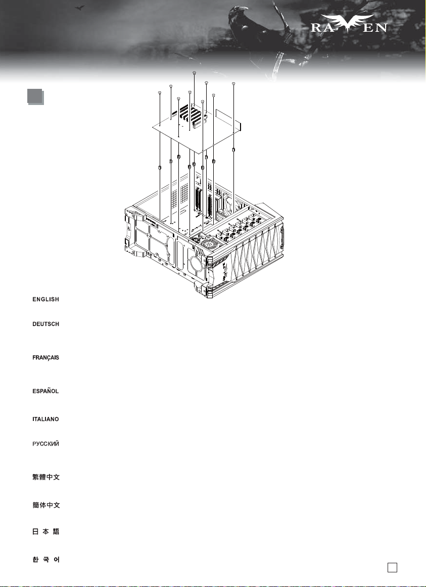
(1) Fan removal guide
1
Remove the four M2*3 screws holding
the fan switch for the 180mm fansfrom
the top panel.
Entfernen Sie die vier M2*3-Schrauben,
die den Lüftermotorschalter der
180 mm-Lüfter befestigen, vom oberen
Paneel.
Открутите четыре шурупа M2*3 на верхней
панели, удерживающих переключатели
режимов 180-мм вентиляторов.
取下鎖固180風扇開關的4顆M2*3的螺絲。
Retirer les quatre vis M2*3 tenant
l'interrupteur du ventilateur pour
les ventilateurs de 180mm par le
panneau supérieur.
Quite los cuatro tornillos M2*3 que sujetan
el interruptor de ventilador para ventiladores
de 180mm del panel superior.
Rimuovere le quattro viti M2*3 che
trattengono l’interruttore delle
ventole da 180mm dal pannello
frontale.
Place the chassis on its side.
2
3
Loosen screws holding the 180mm fans.
Legen Sie das Gehäuse auf die Seite.
Lösen Sie die Schrauben der 180 mm
-Lüfter.
Mettez le boîtier sur le côté.
Desserrez les vis fixant les ventilateurs
de 180mm.
Ponga el chasis de lado.
Desserrez les vis fixant les ventilateurs
de 180mm.
Disporre il case su un lato.
Allentare le viti che tengono le ventole
da 180mm.
Remove 180mm fans. Снимите 180-мм вентиляторы.
取下锁固180风扇开关的4颗M2*3螺丝。
上面パネルから180mmファン用のファンスイ
ッチを支えている4つのM2*3ねじを取り外し
ます。
표시되어있는 상부에서 180mm 팬을 위한
팬 위치에 고정되어 있는 M2*3 나사 4개를
제거하십시오.
Положите корпус на бок.
Отвинтите винты, крепящие 180-мм
вентиляторы.
先推倒機殼。
鬆開180風扇的鎖固螺絲。
先推倒机壳。
松开180风扇的锁固螺丝。
ケースは側面を下にして置きます。
180mmファンを固定しているネジを外します。
먼저 케이스를 밉니다.
180 팬의 잠금 나사를 풀어줍니다.
Entfernen Sie die 180 mm-Lüfter.
Retirez les ventilateurs de 180mm.
Quite los ventiladores de 180mm.
取下180風扇。
取下180风扇。
180mmファンを取り外します。
33
Rimuovere le ventole da 180mm.
180 팬을 꺼냅니다.
Page 35

SERIES
SERIES
Upgrade and maintenance
If you have multiple hard drives behind the motherboard tray, we recommend installing a 120mm fan with speed of at least 600rpm or greater
on the right side panel as an intake fan. To reduce dust intake with a fan installed there, you can optionally purchase a SilverStone FF141
magnetized fan filter to use on the side panel.
Wenn sich in Ihrem System mehrere Festplatten hinter dem Motherboard-Einschub befinden, empfehlen wir die Installation eines 120 mm-Lüfters
(Zuluft) mit einer Geschwindigkeit von mindestens 600 U/min an der rechten Blende. Damit durch den dort installierten Lüfter nicht allzu viel Staub
angesogen wird, können Sie einen optionalen magnetisierten Lüfterfilter (FF141 von SilverStone) erwerben und an der seitlichen Blende anbringen.
Si vous avez plusieurs disques durs derrière le support de votre carte mère, nous vous recommandons d'installer un ventilateur de 120mm
avec une vitesse d'au moins 600 tpm ou plus en tant que ventilateur d'admission sur le panneau latéral de droite. Pour réduire l'accumulation
de poussière avec un ventilateur installé à cet emplacement, vous pouvez acheter un filtre magnétique SilverStone FF141 pour l'utiliser sur
le panneau latéral.
Si tiene varios discos duros tras la bandeja de la placa base, le recomendamos que instale un ventilador de 120mm con una velocidad de al
menos 600rpm ó más en el panel derecho como ventilador de entrada. Para reducir la entrada de polvo con un ventilador instalado allí, tiene
la opción de comprar un filtro magnetizado para ventilador Silverstone FF141 para usarlo en el panel lateral.
Se avete diversi hard disk installati dietro al supporto della scheda madre, vi raccomandiamo di installare una ventola da 120mm, con una
velocità di rotazione di almeno 600rpm, sul pannello laterale destro, posizionata in immissione. Per ridurre gli accumuli di polvere dati dal
posizionamento della ventola, potete acquistare il filtro magnetico SilverStone FF141 da applicare al pannello.
В случае установки нескольких жестких дисков за кронштейном материнской платы в качестве впускного вентилятора рекомендуется
установить 120-мм вентилятор со скоростью не менее 600 об/мин на правой панели. Для сведения к минимуму затягивания пыли этим
вентилятором можно дополнительно приобрести магнитный фильтр для вентилятора SilverStone FF141 для использования на боковой
панели.
如果您在機殼背面有安裝多顆硬碟,
如果擔心灰塵問題, 我們建議您可以購買FF141方便清理灰塵。
如果您在机壳背面有安装多颗硬盘, 我们建议您在右侧板加装一颗120mm风扇, 且设定为进风, 转速至少6~700rpm。
如果担心灰尘问题, 我们建议您可以购买FF141方便清理灰尘。
マザーボードトレイ背後に複数のハードドライブが存在する場合、最低限600rpmまたはそれ以上の回転数の120mmファンを右側パネルに
吸気ファンとしてインストールするよう、お勧めします。インストールされたファンによるホコリの取り込みを減少させるためには、で、
側面パネル用にSilverStone製FF141磁石式ファンフィルタをオプション購入できます。
메인보드 트레이 뒷편에 다수의 하드 디스크를 장착하였다면, 오른쪽 사이드 패널에 흡기용으로 적어도 600rpm 이상의 팬 속도를
갖는 120mm 팬 장착을 권장합니다. 먼지등 이물질의 침투를 최소화하기 위해, SilverStone FF141 자석 팬필터를 사이드패널에 붙여
사용하기를 권장합니다.
我們建議您在右側板加裝一顆120mm風扇, 且設定為進風, 轉速至少6~700rpm。
FF141
34
Page 36

SERIES
SERIES
Upgrade and maintenance
(2) Front panel fan / drive tray installation guide
The front panel fan brackets can be used in a variety of ways to meet your cooling demands.
Please refer to the following instructions:
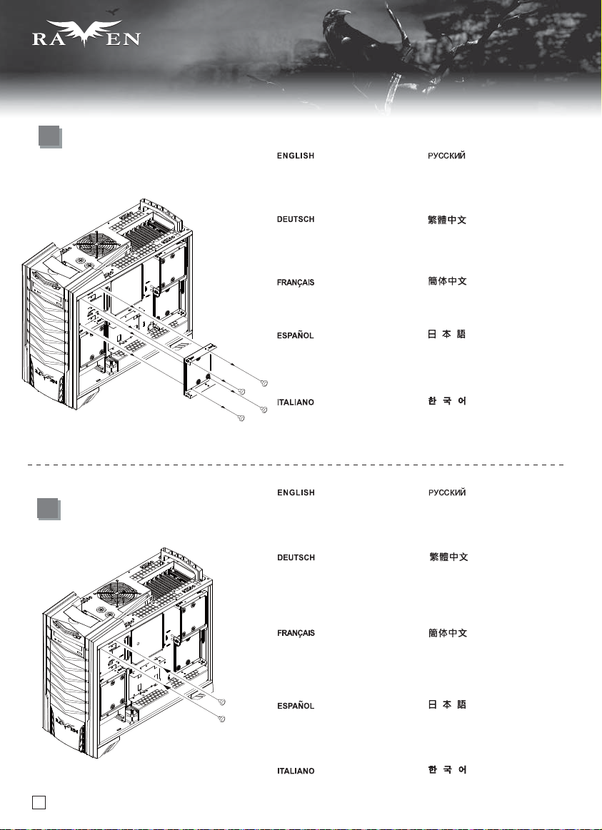
1
1
1
First loosen screws on the right side, then push the entire fan bracket and hard drive tray assemblies toward the front of the chassis
to remove them.
Lösen Sie zuerst die Schrauben an der rechten Seite; drücken Sie dann die gesamte Baugruppe aus Lüfterhalterung und Festplatteneinschub
zum Herausnehmen in den vorderen Teil des Gehäuses.
D'abord veuillez desserrer les vis du côté droit, puis poussez le casier du ventilateur en entier et le support à disques durs assemblé vers
l'avant du boîtier pour les retirer.
Primero afloje los tornillos del lado derecho, luego mueva todo el bracket para el ventilador y la bandeja para disco duro hacia la parte frontal
del chasis para sacarlo.
Per prima cosa rimuovere le viti della parte destra quindi spingere il complesso supporto ventola/hard drive verso la parte frontale dello
chassis per rimuoverlo.
Сначала отвинтите винты с правой стороны, а затем сдвиньте кронштейны для вентиляторов и лотки для жестких дисков в сборе
к передней панели корпуса, чтобы снять их.
先鬆開右方固定螺絲,
先松开右方固定螺丝, 取下整组硬盘架与风扇架, 往前推出机壳。
まず、右側のネジを外して、ファンブラケット全体とハードドライブトレイアセンブリをケース正面へ押して取り外します。
오른쪽에 있는 나사를 푼다음, 팬브라켓 과 하드 드라이브 트레이 어셈블리 전체를 케이스 앞쪽으로 밀어 제거합니다.
35
取下整組硬碟架與風扇架, 往前推出機殼。
Page 37

Upgrade and maintenance
2
1
2
Install fans into the fan brackets as needed.
Installieren Sie die Lüfter wie gewünscht in den Lüfterhalterungen.
Installez les ventilateurs dans leur emplacement selon vos besoins.
SERIES
SERIES
1
Instale ventiladores en los brackets para ventiladores según sea necesario.
Installate le ventole nei supporti come da vostre esigenze.
Установите вентиляторы на кронштейны для вентиляторов, как требуется.
將風扇裝入風扇架。
将风扇装入风扇架。
必要に応じて、ファンブラケット内にファンをインストールします。
필요한 만큼의 팬을 팬 브라켓에 설치합니다.
36
Page 38

SERIES
SERIES
Upgrade and maintenance
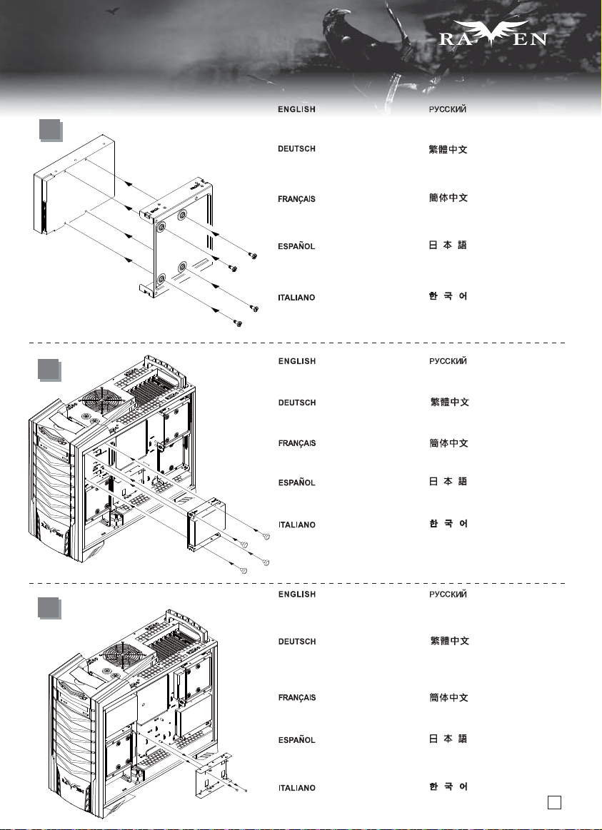
A
2
1
1
If you want to install fans on both front and rear side, we recommend installing the fan brackets to the drive trays and use the tool-less
5.25” drive bay locks to secure the entire assembly.
1
2
Falls Sie Lüfter sowohl an der Vorder- als auch an der Rückseite installieren möchten, empfehlen wir Ihnen, die Lüfterhalterungen an den
Laufwerkseinschüben anzubringen und die werkzeuglosen 5,25 Zoll-Laufwerkseinschubsperren zur Befestigung der gesamten Baugruppe
zu verwenden.
Si vous voulez installer des ventilateurs à l'avant et à l'arrière, nous vous recommandons d'installer les casiers à ventilateurs sur le support
des lecteurs en utilisant le système de fixation sans-outils 5.25” pour fixer le montage.
Si quiere instalar ventiladores en los lados frontal y trasero, le recomendamos instalar los brackets para ventiladores en la bandeja para
dispositivos y usar los cierres de la bahía para dispositivos sin herramientas de 5,25” para asegurar el ensamblaje.
Se volete installare ventole sia sulla parte frontale che posteriore, vi raccomandiamo di montare il supporto ventola nelle sedi ed usare le
staffe di blocco tool-less da 5.25” per assicurare il complesso.
37
Page 39

SERIES
SERIES
Upgrade and maintenance
При необходимости установки вентиляторов и на передней, и на задней панелях рекомендуется установить кронштейны для
вентиляторов в лотки для дисков и закрепить весь блок не требующими применения инструментов фиксаторами отсеко в для
5,25-дюймовых приводов.
如果前後兩端都要安裝風扇, 建議可以將風扇都卡上硬碟架, 利用機殼光碟機的免工具快速安裝。
如果前后两端都要安装风扇, 建议可以将风扇都卡上硬盘架, 利用机壳光驱的免工具快速安装。
ファンを前と後側にインストールする場合、ドライブトレイにファンブラケットをインストールし、アセンブリ全体を固定するためにツール不要の5.25”
ドライブベイロックを使用するようお勧めします。
팬을 전면과 후면에 모두 장착하려 한다면, 팬 브라켓을 드라이브 트레이에 장착하고 툴리스 5.25” 드라이브 베이 락을 이용해 자체
고정시킬 것을 권장합니다.
어셈블리를
38
Page 40

SERIES
SERIES
Upgrade and maintenance
B
2
2
1
If you only need to install fans on the rear side, you can secure the
fan brackets using self-threading screws directly to the chassis.
The mounting holes provided should allow for frontward and rearward
adjustments.
Falls Sie Lüfter an der Rückseite installieren müssen, können Sie
die Lüfterhalterungen durch selbstschneidende Schrauben direkt
am Gehäuse befestigen. Die vorgebohrten Montagelöcher ermöglichen
die Anpassung nach vorne und hinten.
Si vous souhaitez seulement installer des ventilateurs à l'arrière du
boîtier, vous pouvez fixer le casier en utilisant des vis auto taraudeuses
directement sur le boîtier. Les trous de montage disponibles doivent
permettre d'effectuer des réglages vers l'avant et vers l'arrière.
Si sólo necesita instalar ventiladores en la parte trasera, puede
fijar los brackets para ventilador usando los tornillos autorroscantes
directamente contra el chasis. Los agujeros de montaje proporcionados
deberían permitir ajustes frontales y traseros.
Se volete installare ventole soltanto nella parte posteriore, potete
assicurare i supporti allo chassis con le viti autofilettanti fornite in
dotazione. I fori a disposizione consentono aggiustamenti in senso
longitudinale.
39
При необходимости установки вентиляторов на задней панели
можно прикрепить кронштейны для вентиляторов с помощью
винтов-саморезов непосредственно к корпусу. Имеющиеся
монтажные отверстия позволяют регулировать положение в
направлении вперед и назад.
如果只需要安裝後端風扇,可以將風扇架用自攻牙螺絲鎖上機殼,
後方的鎖固孔有相當程度可以前後調整。
如果只需要安装后端风扇,可以将风扇架用自攻牙螺丝锁上机壳,
后方的锁固孔有相当程度可以前后调整。
ファンを後側のみにインストールする必要がある場合、タッピングネジを
使って、ファンブラケットをケースに直接固定します。提供された取り付け
穴は前方、後方への調整が可能です。
후면쪽에만 팬을 장착하려 한다면, 팬브라켓을 나사를 이용해 케이스에
직접 고정시킬 수 있습니다. 마운팅 홀은 전후로 조절이 가능하도록 되어
있습니다.
Page 41

Upgrade and maintenance
C
SERIES
SERIES
If you need to install fans to the front, please use at least two hard
drive trays to secure the fan brackets.
Falls Sie Lüfter an der Vorderseite installieren müssen, verwenden
Sie zur Befestigung der Lüfterhalterung bitte mindestens zwei
Festplatteneinschübe.
Si vous avez besoin d'installer des ventilateurs à l'avant,
veuillez utiliser au moins deux fixations pour disques durs
pour fixer correctement le casier du ventilateur.
Si necesita instalar ventiladores en la parte frontal, use por favor al
menos dos bandejas para discos duros para asegurar los brackets
para ventilador.
Se avete bisogno di installare ventole sul frontale, utilizzare almeno
due tray per hard drive per assicurare i supporti delle ventole stesse.
При необходимости установки вентиляторов на передней
панели прикрепите кронштейны для вентиляторов как
минимум к двум лоткам для жестких дисков.
如果只需要安裝前端風扇, 請至少利用兩個硬碟架來固定風扇。
如果只需要安装前端风扇, 请至少利用两个硬盘架来固定风扇。
正面にファンをインストールする必要がある場合、ファンブラケットを
固定するには、最低2つのハードドライブトレイを使います。
팬을 전면에만 설치한다면, 적어도 두개의 하드 드라이브 트레이를
이용해 팬브라켓을 고정시킵니다.
40
Page 42

SERIES
SERIES
Upgrade and maintenance
D
If you need to install a lot of hard drives, the rear fan brackets will
need to be removed, but you can still use the tool-less 5.25” drive
bay locks for quick assembly.
Falls Sie zahlreiche Festplatten installieren möchten, müssen
die hinteren Lüfterhalterungen entfernt werden; Sie können zur
schnellen Montage jedoch immer noch die werkzeuglosen 5,25
Zoll-Laufwerkseinschubsperren verwenden.
Si vous avez besoin d'installer beaucoup de disques durs, le casier
du ventilateur arrière doit être démonté, mais vous pouvez toujours
utiliser les fixations sans outils 5.25” pour un montage rapide.
Si necesita instalar un montón de discos duros, los brackets para
ventiladores traseros deberán ser retirados, pero puede seguir
usando los cierres sin herramientas de la bahía de dispositivos
de 5,25” para un ensamblaje rápido.
Se avete bisogno di installare molti hard drive, sarà necessaria
la rimozione dei supporti per ventole posteriori, ma potete ancora
utilizzare le staffe tool less dei bay da 5.25” per un assemblaggio
veloce.
41
При необходимости установки большого количества жестких
дисков потребуется снять кронштейны для вентиляторов на
задней панели, но для быстрой сборки можно использовать
не требующие применения инструментов фиксаторы отсеков
для 5,25-дюймовых приводов.
如果前方要裝很多顆硬碟, 必須先移除後風扇架, 您一樣可以利用機殼
光碟機的免工具快速安裝。
如果前方要装很多颗硬盘, 必须先移除后风扇架, 您一样可以利用机壳
光驱的免工具快速安装。
多数のハードドライブをインストールする必要がある場合、後部ファンブ
ラケットを取り外す必要がありますが、敏速なアセンブリのためにはツー
ル不要5.25”ドライブベイロックを使用できます。
많은 수의 하드 드라이브를 장착할 경우 후면 팬 브라켓을
제거해아 하지만, 툴리스 5.25” 드라이브베이 잠금장치를
이용해 고정시킬 수는 있습니다.
Page 43

SERIES
SERIES
Upgrade and maintenance
(3) Fan filter removal guide
An example of a GPU cooler that is filled with dust and
has lost most of its cooling performance
RV03’s positive air pressure design is an effective configuration that will reduce dust buildup inside the case. Small air particles or lint will accumulate over
time on intake filters instead of on the components inside the case. To maintain RV03’s excellent cooling performance for years to come, we recommend to
clean all fan filters regularly every three months or half a year (depending on your environment). Below are steps to remove fan filters.
Das vorteilhafte Luftdruckdesign des RV03 ist eine effektive Konfiguration, die Staubablagerungen innerhalb des Gehäuses vermindert. Im Laufe der Zeit
sammeln sich kleine Partikel und Fusseln an den Luftzufuhrfiltern, anstatt an den Komponenten im Gehäuseinneren, an. Sie können eine jahrelange optimale
Kühlleistung des RV03 gewährleisten, indem Sie alle Lüfterfilter regelmäßig alle drei bis sechs Monate reinigen (je nach Umgebungsbedingungen).
Nachstehend finden Sie die Schritte zur Entfernung der Lüfterfilter.
La conception à pression d'air positive du RV03 est une configuration efficace permettant de réduire l'accumulation de la poussière dans le boîtier. De petites
particules d'air ou de peluche vont s'accumuler avec le temps sur les filtres d'aspiration, et non sur les composants à l'intérieur du boîtier. Pour conserver les
excellentes performances de refroidissement du RV03 au fil des ans, nous vous recommandons de nettoyer l'ensemble des filtres des ventilateurs, tous les trois
ou six mois (selon votre environnement). Vous trouverez ci-dessous les étapes vous expliquant comment retirer les filtres des ventilateurs.
El diseño de presión de aire positiva de la RV03 es una configuración efectiva que reducirá la acumulación de polvo dentro de la carcasa. Pequeñas
partículas de polvo ó pelusa se irán acumularán con el transcurso del tiempo en los filtros de entrada en lugar de en los componentes del interior de la
carcasa. Para mantener la excelente capacidad de refrigeración de la RV03 en años venideros, le recomendamos que limpie con regularidad todos los
filtros de los ventiladores cada tres meses ó seis meses (dependiendo de dónde viva). A continuación están los pasos para quitar los filtros de los ventiladores.
Il design a pressione positiva di RV03 riduce considerevolmente gli accumuli di polvere all’interno del case. Le piccole particelle si accumulano infatti sui filtri
invece che sui componenti interni. Per mantenere le eccellenti prestazioni di raffreddamento di RV03 negli anni a venire vi raccomandiamo di procedere ad
una regolare pulizia dei filtri (con cadenza trimestrale o semestrale dipendentemente dall’ambiente un cui è disposto il sistema). Di seguito i passi per la
rimozione dei filtri.
Конструкция корпуса RV03 обеспечивает избыточное давление воздуха и, таким образом, имеет эффективную конфигурацию, препятствующую
скоплению пыли внутри корпуса. Небольшие частицы и волокна, содержащиеся в воздухе, со временем будут скапливаться на впускных фильтрах,
а
не на компонентах, находящихся внутри корпуса. Для поддержания превосходного охлаждения компонентов в корпусе RV03 в течение многих лет
рекомендуется регулярно очищать все фильтры вентиляторов: раз в 3 месяца или раз в полгода (в зависимости от условий окружающей среды).
Ниже приведена процедура для удаления фильтров вентиляторов.
RV03正壓差搭配濾網方式是經的起時間考驗的高效率防塵方式,在使用相當長一段時間後,棉屑灰塵或其他可能妨礙散熱效能的小異物只會卡在濾網,
而不是電腦內的元件上面。我們重視的散熱效能,是在您使用電腦長達2~3年後還能維持與全新的無異。為了維持這種散熱效能您只需要定期清理濾網,
而不是電腦裡面的元件。視環境而定,我們建議您每3個月~半年必須清理濾網,以下是濾網的拆卸步驟。
RV03正压差搭配滤网方式是经的起时间考验的高效率防尘方式,在使用相当长一段时间后,棉屑灰尘或其它可能妨碍散热效能的小异物只会卡在滤网,
而不是计算机内的组件上面。我们重视的散热效能,是在您使用计算机长达2~3年后还能维持与全新的无异。为了维持这种散热效能您只需要定期清理滤网,
而不是计算机里面的组件。视环境而定,我们建议您每3个月~半年必须清理滤网,以下是滤网的拆卸步骤。
RV03の正圧設計は、ケース内のホコリの蓄積を減少させる有効な構造です。時と共に空気中の微粒子または糸くずはケース内のコンポーネント上の代わり
に取入れ口フィルタに溜まります。この先何年もの間RV03の素晴らしい冷却性能を維持するには、全てのファンを3ヶ月ないしは半年(環境に依存)ごとに
規則的に清掃するようお勧めします。以下は、ファンフィルタを取り外す手順です。
RV03의 양압 디자인은 케이스 내부에 먼지가 싸이는 것을 방지 하기 위한 효과적인 디자인입니다. 작은 분진이나 먼지는 케이스 내부에 있는 필터에
시간에 따라 쌓이게 됩니다. RV03의 우수한 냉각 성능을 계속 유지하기 위헤서 매 3개월 혹은 6개월(사용환경에 따라)마다 필터 청소를 권장합니다.
다음의 필터 제거 과정을 참고하세요.
42
Page 44

SERIES
SERIES
Upgrade and maintenance
Pull to remove filter. Потяните, чтобы снять фильтр.
(5) ClearCMOS
RV03 supports SST-CLEARCMOS installation on a designated
part of the case, please see example below:
Das RV03 unterstützt die SST-CLEARCMOS-Installation an
einem dazu vorgesehenen Teil des Gehäuses; bitte halten Sie
sich an das nachstehende Beispiel:
Le RV03 est compatible avec l'installation du SST-CLEARCMOS
dans une partie spéciale du boîtier, voici un exemple ci-dessous:
La RV03 acepta la instalación de SST-CLEARCMOS en una parte
dedicada a ello en la carcasa, por favor vea el ejemplo siguiente:
RV03 supporta l’installazione, in una specifica zona del case,
di SST-CLEARCMOS, come da esempio seguente:
Ziehen Sie den Filter heraus.
Tirez pour démonter le filtre.
Tire para retirar el filtro.
Tirare per rimuovere il filtro.
В корпусе RV03 в специально отведенном месте может быть
установлен разгонщик SST-CLEARCMOS, ниже приводится пример:
RV03支援SST-CLEARCMOS安裝在非佔用Slot卡槽的地方,請參考下圖:
RV03支持SST-CLEARCMOS安装在非占用Slot卡槽的地方,请参考下图:
RV03はケースの指定された部分でのSST-CLEARCMOSインストールに
対応しています。下の例をご参照ください:
RV03는 SST-CLEARCMOS 설치는 아래 예와 같이 케이스에
지정된 부분에 설치합니다:
把濾網整個抽出。
把滤网整个抽出。
フィルタを引っ張って取り外します。
필터 전체를 빼냅니다.
43
Page 45

SERIES
SERIES
Q & A
Q: If I have a tower-style CPU cooler, is it possible to run it without CPU fan installed?
A: From the tests we’ve conducted during development, a quality tower-style cooler can be
used without CPU fan and instead rely only on chassis fans to cool CPU up to 130W TDP
(Core i7, not overclocked). However, performance may vary depending on the quality of your
CPU cooler and other factors, so you will still need to test the limit on your own.
F: Ich habe einen Tower-CPU-Kühler; ist es möglich, ihn ohne installierten CPU-Lüfter laufen zu lassen?
A: Gemäß den von uns während der Entwicklung durchgeführten Tests kann zur Kühlung der CPU
(Core i7, nicht übertaktet) ein hochwertiger Tower-Kühler ohne CPU-Lüfter genutzt werden; stattdessen
kann die Kühlung der CPU (bis 130 W, TDP) ausschließlich den Gehäuselüftern überlassen werden.
Die Leistung kann jedoch je nach Qualität Ihres CPU-Kühlers und anderer Faktoren variieren; Sie müssen
die Begrenzungen also selbst testen.
Q: Si j'ai un dissipateur de processeur de type tour, est-il possible de l'utiliser sans ventilateur?
R: A partir des tests que nous avons menés durant le développement, un dissipateur de type tour peut être utilisé
sans ventilateur et ainsi dépendre des ventilateurs du boîtier pour refroidir le processeur ayant un TDP jusqu'à 130W
(Core i7, non overclocké). Cependant, les performances peuvent variées en fonction de la qualité du dissipateur et d'autres facteurs,
donc vous devez vous-même tester les limites de votre système.
P: Si tengo un disipador para CPU tipo torre, ¿es posible usarlo sin un ventilador para CPU instalado?
R: Por las pruebas que se realizaron durante el desarrollo, un disipador tipo torre se puede usar sin ventilador de CPU y confiar en los ventiladores del
chasis para enfriar la CPU hasta 130V TDP (Core i7 sin overclocking). Sin embargo, el rendimiento podría variar dependiendo de la calidad de su disipador
para CPU y otros factores, luego tendrá que probar usted mismo los límites.
D: Se possiedo un dissipatore per CPU a torre, è possibile utilizzarlo senza montare le ventole in dotazione?
R: Dai test condotti, è possibile utilizzare un dissipatore per CPU a torre di qualità senza alcuna ventola montata, (sfruttando per il raffreddamento la
ventilazione offerta dalle ventole del case) con CPU che abbiano un TDP massimo di 130W (Core i7 non overclockato). Naturalmente le prestazioni
possono variare a seconda di diversi fattori, non ultimo la qualità del dissipatore, avrai quindi bisogno di testare da solo il limite della configurazione.
Вопрос: При наличии процессорного кулера башенного типа можно ли обойтись без установки процессорного вентилятора?
Ответ: На основании испытаний, проведенных во время разработки оборудования, мы установили, что качественный процессорный кулер башенного
типа можно использовать без процессорного вентилятора и ограничиться только корпусными вентиляторами для охлаждения ЦП с тепловым пакетом
(TDP) до 130 Вт (Core i7, без
поэтому рекомендуется выполнить собственную проверку предельной нагрузки.
Q: 若我使用高塔型的CPU散熱器, 是否可以不用裝風扇?
A:根據我們的測試, 在Core i7 130W TDP且未超頻的狀態下, CPU散熱器能夠以無風扇運作; 但實際上還要根據您所購買的散熱器等級而定,
狀況可能會不完全相同。可以試試看, 但是我們不保證可以完全支援。
Q: 若我使用高塔型的CPU散热器, 是否可以不用装风扇
A:根据我们的测试, 在Core i7 130W TDP且未超频的状态下, CPU散热器能够以无风扇运作; 但实际上还要根据您所购买的散热器等级而定,
状况可能会不完全相同。可以试试看, 但是我们不保证可以完全支持。
Q: タワータイプCPUクーラーがある場合、CPUファンをインストールせずに稼働することは可能ですか?
A:当社が開発時に実施したテストでは、高品質のタワータイプクーラーは、CPUファンなしで、最高130W TDP(コアi7、オーバークロックなし)のCPU
をケースファンに頼って冷却することができます。しかし、性能はCPUクーラーと他の要因によって変わる可能性があるので、ご自身で限界をテストす
る必要があるでしょう。
Q: 만약 타워형 CPU 쿨러를 사용할 경우 CPU팬 없이 사용 가능할까요 ?
A: 개발단계에서 다양한 시험이 이루어 졌는데, 고품질의 타워형 쿨러는 CPU팬 없이도 케이스의 팬을 이용해 최대 130W TDP (Core i7, 오버클럭 안한 상태)
까지
냉각에 문제가 없었던걸 확인한 바 있습니다. 그러나, 냉각 성능은 CPU쿨러의 성능과 다른 요인들에 의해 많은 차이를 보일 수 있어, 자신의 판단과 경험에
의해 결정해야 하며, 실버스톤은 이에 대한 책임을 질 수 없습니다. (가급적 팬 사용을 권장합니다.)
разгона). Однако эффективность охлаждения может зависеть от качества процессорного кулера и других факторов,
?
44
Page 46

SERIES
SERIES
Q & A
Q: If I want to install fans to the front panel, what are your recommendations?
A: RV03’s front panel and its fan brackets are designed to be flexible in providing users with multiple cooling options. If quietness is a priority, then we
recommend not installing any fans into the front panel to prevent noise from leaking out to the front of the chassis. If you want to increase cooling performance,
we recommend first to install two 120mm fans in the rear side of the 5.25’ drive bays. This will increase cooling performance to very high levels due to close
proximity with the internal heat source (e.g. CPU) while keeping noise low since the fans are located further away from the front panel. We also highly
recommend installing an optical drive into the top 5.25” drive bay when fans are installed in the front panel to create an air duct. The airflow layout of the RV03
is so powerful that most systems will not see any difference between having two or four fans installed into the front panel.
F: Ich möchte Lüfter an der Frontblende installieren; gibt es irgendwelche Empfehlungen?
A: Die Frontblende des RV03 und deren Lüfterhalterungen ermöglichen dem Benutzer durch ihr Design verschiedene Kühloptionen. Wenn für Sie ein möglichst
geräuscharmer Betrieb im Vordergrund steht, empfehlen wir, keine Lüfter an der Frontblende zu installieren; andernfalls können deren Betriebsgeräusche durch
die Vorderseite des Gehäuses dringen. Wenn Sie die Kühlleistung steigern möchten, empfehlen wir Ihnen, zuerst zwei 120 mm-Lüfter an der Rückseite der 5,25
Zoll-Laufwerkseinschübe zu installieren. Dadurch wird die Kühlleistung aufgrund der Nähe zu internen Hitzequellen (z. B. CPU) deutlich erhöht, während durch
die größere Entfernung zur Frontblende zudem ein geräuschärmerer Betrieb gewährleistet wird. Außerdem raten wir Ihnen zur Erzeugung eines Luftkanals
dringend, ein optisches Laufwerk im oberen 5,25 Zoll-Laufwerkseinschub zu installieren, wenn Lüfter an der Frontblende angebracht sind. Das Luftstrom-Layout
des RV03 ist so leistungsstark, dass die meisten Systeme keinen Unterschied zwischen dem Einsatz von zwei oder vier Lüftern an der Frontblende feststellen.
Q: Si je veux installer des ventilateurs à l'avant du boîtier, quelles sont vos recommandations?
R: Le panneau frontal du RV03 et ses casiers pour ventilateurs sont conçus pour être flexible en procurant aux utilisateurs de multiples possibilités de
refroidissement. Si le silence est votre priorité, alors nous vous recommandons de ne pas installer de ventilateurs sur la face avant afin de prévenir la
diffusion du bruit par l'avant. Si vous voulez améliorer les performances de refroidissement, nous vous recommandons d'abord d'installer deux ventilateurs
de 120mm à l'arrière des baies des lecteurs 5.25’. Ceci améliorera grandement les performances de refroidissement à cause de la proximité avec les
sources de chaleur interne (ex: Processeur) tout en gardant le niveau sonore faible car les ventilateurs seront situés plus loin du panneau frontal. Nous
vous recommandons aussi grandement d'installer un lecteur optique dans la baie 5.25” la plus haute lorsque les ventilateurs sont installés sur le panneau
frontal afin de créer un conduit d'air. La gestion des flux d'air à l'intérieur du RV03 est si puissante que la plupart des systèmes ne verront aucune différence
entre l fait d'avoir deux ou quatre ventilateur installés dans le panneau frontal.
P: Si quiero instalar ventiladores en el panel frontal, ¿cuáles son sus recomendaciones?
R: El panel frontal de la RV03 y sus brackets para ventilador están diseñados para ser flexibles a la hora de proporcionar a los usuarios múltiples opciones
de refrigeración. Si la baja sonoridad es una prioridad, entonces le recomendamos que no instale ningún ventilador en el panel frontal para evitar que el ruido
se escuche a través del frontal del chasis. Si quiere aumentar la refrigeración, le recomendamos que instale primero dos ventiladores de 120mm en la parte
posterior de las bahías para dispositivos de 5,25”. Esto llevará la capacidad de refrigeración a niveles muy altos debido a su proximidad con la fuente de calor
interna (por ejemplo, la CPU) a la vez que el nivel de sonido se mantiene bajo ya que los ventiladores están localizados lejos del panel frontal. También le
recomendamos encarecidamente que instale un dispositivo óptico en la bahía para dispositivos superior de 5,25” cuando los ventiladores estén instalados
en el panel frontal para crear un conducto de aire. La disposición del flujo de aire de la RV03 es tan poderosa que la mayoría de los sistemas no verá ninguna
diferencia entre tener dos ó cuatro ventiladores instalados en el panel frontal.
D: Se voglio installare ventole sul pannello frontale, quali sono le vostre raccomandazioni?
R: Il pannello frontale di RV03 ed i suoi supporti per ventole sono stati progettati per offrire la massima flessibilità offrendo molteplici configurazioni di
raffreddamento. Se la silenziosità del sistema è per te fondamentale, ti raccomandiamo di non installare alcuna ventola nel pannello frontale al fine di
evitare che il rumore prodotto dalle ventole provenga direttamente dalla parte anteriore del case. Se vuoi invece incrementare le prestazioni di raffreddamento,
ti raccomandiamo, per prima cosa, di installare due ventole da 120mm nella parte posteriore dei bays da 5,25”. Questo aumenterà di molto la capacità di
raffreddamento data la vicinanza delle fonti di calore interne (es. CPU) ma terrà basso il li livello di rumorosità essendo le ventole posizionate lontano dal
pannello frontale. Altro consiglio è quello di installare un drive ottico nel bay posto più in alto, quando le ventole vengono montate sul pannello frontale, al
fine di creare un condotto d’aria. Il flusso d’aria di RV03 è stato talmente ottimizzato che non noterete differenze utilizzando due o quattro ventole montate
sul pannello frontale.
45
Page 47

SERIES
SERIES
Q & A
Вопрос: Каковы рекомендации по установке вентиляторов на передней панели?
Ответ: Передняя панель корпуса RV03 и ее универсальные кронштейны для вентиляторов позволяют пользователям устанавливать вентиляторы
различными способами. Если приоритет отдается бесшумной работе, рекомендуется вообще не устанавливать вентиляторы на переднюю панель
для предотвращения выхода шумов через переднюю панель корпуса. Если требуется повысить эффективность охлаждения
два 120-мм вентилятора на заднюю часть отсеков для 5,25-дюймовых приводов. Это повысит эффективность охлаждения до очень высокого уровня
благодаря непосредственной близости вентиляторов к внутреннему источнику тепла (ЦП) при поддержании низкого уровня шума вследствие
расположения вентиляторов на достаточном расстоянии от передней панели. Кроме того, в случае установки вентиляторов на
настоятельно рекомендуется установить оптический привод в верхний отсек для 5,25-дюймовых приводов для создания вентиляционного канала.
Распределение воздушных потоков в корпусе RV03 настолько эффективное, что для большинства систем не будет заметна разница при установке
двух или четырех вентиляторов на передней панели.
Q: 前方如果要增加風扇, 建議如何安裝?
A: RV03的前方風扇架是為了符合各種不同玩家對靜音的需求而設計。如果您對噪音非常在意, 建議前方不要裝任何風扇, 以免噪音從前方洩出。
如果您想要提升散熱效能, 則光碟架後端可以增加兩顆相容120mm風扇向後吹, 就可以將散熱效能提升到無可匹敵。風扇安置在光碟架後端會離熱源比較近
人耳離噪音源也比較遠, 靜音與散熱效果都有很大的提升。此時, 不論您有沒有使用光碟機, 我們建議在最上面一槽安裝光碟機以維持風道。
由於RV03的氣流規畫已經非常優異, 因此前方安裝2顆或4顆風扇的差異不大。
Q: 前方如果要增加风扇, 建议如何安装?
A: RV03的前方风扇架是为了符合各种不同玩家对静音的需求而设计。如果您对噪音非常在意, 建议前方不要装任何风扇, 以免噪音从前方泄出。
如果您想要提升散热效能, 则光盘架后端可以增加两颗兼容120mm风扇向后吹, 就可以将散热效能提升到无可匹敌。风扇安置在光盘架后端会离热源比较近;
人耳离噪声源也比较远, 静音与散热效果都有很大的提升。此时, 不论您有没有使用光驱, 我们建议在最上面一槽安装光驱以维持风道。
由于RV03的气流规画已经非常优异, 因此前方安装2颗或4颗风扇的差异不大。
Q: フロントパネルにファンをインストールする場合、何がお勧めですか?
A: RV03のフロントパネルとそのファンブラケットは、ユーザに複数の冷却オプションを提供する柔軟性を持つよう設計されています。
静音が優先される場合、ノイズがケース正面から漏れないようにフロントパネルにはいずれのファンもインストールしないようお勧めします。
冷却性能を向上させたい場合、まず5.25’ドライブベイ後方に2台の120mmファンを並べてインストールするようお勧めます。これで、ファンは
フロントパネルから離れていてノイズを低減されつつ、内部の熱発生源(例えばCPU)に非常に近接しているため、高いレベルの冷却性能が実現
されます。 ファンがフロントパネルにインストールされる場合、通風ダクトを構成するよう、最上部の5.25インチのドライブベイ内に光学ドラ
イブをインストールするよう強くお勧めします。RV03の気流レイアウトはとても強力なので、ほとんどのシステムで、フロントパネル内に、2
ないし4台のファンをインストールした状態と大差ないことに気づかれるでしょう。
, рекомендуется установить
передней панели
;
Q: 팬을 전면패널에 설치하려는데, 권장사항은 무엇인가요?
A: RV03의 전면패널과 팬브라켓을 사용자에게
경우, 전편 패널에 팬을 달지 않아, 케이스에서 소음이 흘러 나오지 않도록 하는게 좋습니다. 냉각 성능을 올리고자 할 경우, 두개의 120mm 팬을 5.25” 드라이브
베이 후면에 설치할 것을 권합니다. 이 경우 열원 (CPU 등)에서 가까워 냉각 성능을 상당히 높일 수
수 있습니다. 이 경우 광드라이브를 5.25 드라이브 베이 최상부에 설치하여, 공기 덕트를 구성할 수 있도록 해줄 것을 권장합니다.
RV03의 공기 흐름 레이아웃은 아주 강력해, 대부분의 시스템에서, 2개 혹은 4개의 팬이 장착된 차이를 느끼지 못할 것입니다.
다양한 냉각 옵션을 제공하기위해 최대한 융통성을 발휘할 수 있도록 디자인되었습니다. 정숙성이 가장 중요한
있을 뿐만아니라, 전면패널에서 멀리떨어져 있어 소음도 낮출
46
Page 48

SERIES
SERIES
Q & A
Q: How do I increase cooling to hard drives installed behind the motherboard tray?
A: You can install a 120mm fan to the right side panel to increase cooling to that area.
F: Wie steigere ich die Kühlung der hinter dem Motherboard-Einschub installierten Festplatten?
A: Zur Steigerung der Kühlung in diesem Bereich können Sie einen 120 mm-Lüfter an der rechten Blende installieren.
Q: Comment puis-je améliorer le refroidissement des disques durs installés derrière le support de la carte mère?
R: Vous pouvez installer un ventilateur de 120mm sur le panneau latéral droit pour améliorer le refroidissement de cette zone.
P3. ¿Cómo aumento la refrigeración de los discos duros instalados tras la bandeja de la placa base?
R3. Puede instalar un ventilador de 120mm en el panel derecho para aumentar la refrigeración de esa zona.
D: Come posso incrementare il raffreddamento degli hard drive montati posteriormente al supporto della motherboard?
R: Puoi installare una ventola da 120mm sul pannello laterale destro per aumentare il flusso d’aria in quella zona.
Вопрос: Как улучшить охлаждение жестких дисков, установленных за кронштейном материнской платы?
Ответ: Можно установить 120-мм вентилятор на правую панель для усиления охлаждения этой области.
Q: 將硬碟安置在背面, 那該如何散熱?
A: 可以在右側板處安裝一顆120mm風扇, 以強化背面硬碟的散熱。建議可另購FF141方便清理灰塵。
Q: 将硬盘安置在背面, 那该如何散热?
A: 可以在右侧板处安装一颗120mm风扇, 以强化背面硬盘的散热。建议可另购FF141方便清理灰尘。
Q: マザーボードトレイ背後にインストールされたハードドライブへの冷却性能を増大させるにはどうしますか?
A: そのエリアでの冷却効果を増大させるには、右側パネルに120mmファンをインストールすることができます。
Q: 메인보드 트레이 뒷편에 장착된 하드 드라이브의 냉각 성능을 향샹시키는 방법이 있나요?
A: 120mm 팬을 오른쪽 사이드 패널에 장착해 그 영역의 냉각을 향상 시킬 수 있습니다.
47
Page 49

Q & A
SERIES
SERIES
Q: Why put hard drives behind the motherboard tray?
A: There are two reasons:
1. Maximum use of space – for novice users, RV03’s spacious 5cm gap
behind the motherboard tray allows for generous room to easily route
extra cables. For more advanced builders good at routing cables, the
extra room provides spaces to mount hard drives for more flexibility in storage.
2. Better cable management – placing hard drives behind the motherboard
tray also helps to hide cables connected to the hard drives.
F: Warum sollte ich Festplatten hinter dem Motherboard-Einschub installieren?
A: Dies hat zwei Gründe:
1. Maximale Raumnutzung – unerfahrenen Benutzern bietet der großzügige
5 cm-Freiraum des RV03 hinter dem Motherboard-Einschub genügend Platz
zur einfachen Führung zusätzlicher Kabel. Benutzer mit viel Erfahrung bei
der Kabelführung können den zusätzlichen Platz zur Installation von
Festplatten nutzen und dadurch von mehr Speicherflexibilität profitieren.
2. Bessere Kabelverwaltung – durch die Installation der Festplatten hinter
dem Motherboard-Einschub können Sie zudem die mit den Festplatten
verbundenen Kabel verdecken.
Q: Pourquoi mettre les disques durs derrière le support de la carte mère?
R4. Il y a deux raisons :
1. Utilisation maximale de l'espace – pour les utilisateurs débutants,
l'espace généreux de 5cm derrière le support de carte mère du RV03
permet de facilement faire passer des câbles. Pour les monteurs plus
expérimentés dans le routage des câbles, l’espace supplémentaire permet
le montage des disques durs pour un stockage plus flexible.
2. Meilleure gestion des câbles – le fait de placer les disques durs derrière
le support de la carte mère aide également à cacher els câbles branchés
aux disques durs.
Вопрос: Почему жесткие диски следует устанавливать за кронштейном
материнской платы?
Ответ: Для этого есть две причины.
1. Оптимальное использование пространства – для начинающих
пользователей большой 5-см зазор за кронштейном материнской платы
в корпусе RV03 обеспечивает достаточное пространство для легкой
прокладки дополнительных кабелей. Продвинутым сборщика систем,
имеющим большой опыт прокладки кабелей, это свободное пространство
дает возможность установить дополнительные жесткие диски для большей
гибкости хранения данных.
2. Оптимальное распределение кабелей – размещение жестких дисков за
кронштейном материнской платы также помогает скрыть кабели, подсоединенные
к жестким дискам.
Q: 為何把硬碟安置在背面?
A: 1. 利用空間。對於首次使用背位理線的新手而言, RV03在背面保留
了5cm的空間, 方便玩家隨意安置多餘的線材。對於有能力壓縮理線空
間的玩家, 這些多出來的空間, 可以安置更多硬碟
2. 整線考量。把所有硬碟放到背面有助於減少露出在正面的線材, 增加
煙囪效應的散熱效果。
Q: 为何把硬盘安置在背面?
A: 1. 利用空间。对于首次使用背位理线的新手而言, RV03在背面保留
了5cm的空间, 方便玩家随意安置多余的线材。对于有能力压缩理线空
间的玩家, 这些多出来的空间, 可以安置更多硬盘, 以容纳更大量的数据。
2. 整线考虑。把所有硬盘放到背面有助于减少露出在正面的线材, 增加
烟囱效应的散热效果。
, 以容納更大量的資料。
P: ¿Por qué se pusieron discos duros tras la bandeja de la placa base?
R: Existen dos razones:
1. Máximo aprovechamiento del espacio: para los usuarios novatos, el
amplio hueco de 5cm de la RV03 tras la bandeja de la placa base proporciona
un generoso espacio para enrutar cables extra con facilidad. Para los usuarios
más avanzados que sean expertos en enrutar cables, el espacio extra permite
montar discos duros para tener más flexibilidad en el almacenamiento.
2. Mejor manejo de los cables: situar discos duros tras la bandeja de la placa
base también ayuda a esconder cables conectados a los discos duros.
D: Perchè montare gli hard disk nella parte posteriore del supporto della
motherboard?
R: Ci sono due ragioni:
1. Massimizzare l’utilizzo dello spazio. Per utenti alle prime armi, il gap di
ben 5cm tra la parte posteriore della scheda madre ed il pannello laterale
permette un eccellente sistemazione dei cavi. Per utenti più esperti nel cable
routing, il vano extra fornisce spazio per il montaggio degli hard disk, per una
maggiore flessibilità di storage.
2. Un migliore cable management – Porre gli hard disk dietro al supporto
della scheda madre permette di nascondere meglio i cavi connessi agli hard
disk stessi.
Q: ハードドライブをマザーボードトレイ背後に配置した理由は何ですか?
A: 以下の2つの理由があります。
1. スペースの最大活用-初心者ユーザにとって、RV03におけるマザーボードト
レイ背後の大きな5cmのギャップにより、ケーブル取り回しが容易になります。
またケーブル取り回しの経験を積んだユーザには、ストレージにより多くの柔軟
性を持たせるハードドライブをマウントする余分のスペースを提供します。
2. より優れたケーブル管理-マザーボードトレイ背後にハードドライブを設置す
ることは、ハードドライブと接続されたケーブルを目立たなくすることに役立っ
ています。
Q: 왜 하드 드라이브를 메인보드 뒷편에 설치하게 되었나요?
여기에는 두가지 이유가 있습니다.
1. 공간의 최대 활용 : 초보자에게도 RV03의 메인보드 트레이 뒷편의 5cm 공간은
여분의 케이블을 정리하기위해 넉넉한 공간이 되며, 고급 사용자에게는 케이블
정리는 물론, 하드 드라이블 설치할 수 있는 공간을 활용할 수 있어 저장공간의
융통성을 극대화 하였습니다.
2. 케이블 정리 : 하드 드라이브를 메인보드 트레이 뒷편에 위치시킴으로써 하드
드라이브를 연결하는 케이블을 노출 시키지 않을 수 있습니다.
48
Page 50

SERIES
SERIES
Q & A
Q: The 2.5” drive bracket is getting in the way of my routed cables, what should I do?
A: If you still have vacant 3.5” drive trays, you can replace them with the 2.5” drive bracket, which is compatible in any 3.5” drive bays.
F: Die 2,5 Zoll-Laufwerkshalterung stört mich bei der Kabelführung; was soll ich tun?
A: Falls Sie noch freie 3,5 Zoll-Laufwerkseinschübe haben, können Sie diese durch die 2,5 Zoll-Laufwerkshalterung ersetzen, die mit allen
3,5 Zoll-Laufwerkseinschüben kompatibel ist.
Q: Le casier pour lecteur 2.5” est sur le passage de mes câbles, que dois-je faire?
R: Si vous avez encore une baie 3.5” libre, vous pouvez y mettre votre casier 2.5”, qui est compatible avec toutes les baies 3.5”.
P: El bracket para dispositivo de 2,5” está en medio de mis cables enrutados, ¿qué debería hacer?
R: Si aún tiene espacios para dispositivos de 3,5” sin usar, puede reemplazarlos con el bracket para dispositivos de 2,5”, que puede ser alojado
en cualquier bahía para dispositivos de 3,5”
D: Il supporto dei drive da 2,5” intralcia i cavi da me sistemati, cosa posso fare?
R: Se hai vani da 3,5” ancora liberi, puoi utilizzarli per il supporto da 2,5”, la compatibilità è garantita.
Вопрос: Кронштейн для 2,5-дюймового привода мешает прокладке кабелей. Что делать?
Ответ: Если у вас еще имеются свободные отсеки для 3,5-дюймовых дисков, можно заменить один из них на кронштейн для 2,5 дюймового
диска, который совместим со всеми отсеками для 3,5-дюймовых дисков.
Q: 2.5”硬碟架讓我難以在機背整線, 請問要怎麼辦?
A: 如果您還有尚未利用的3.5”硬碟槽位, 此顆2.5”硬碟架能安裝在3.5”硬碟槽位中, 藉由轉接的方式能降低整線難度。
Q: 2.5”硬盘架让我难以在机背整线, 请问要怎么办?
A: 如果您还有尚未利用的3.5”硬盘槽位, 此颗2.5”硬盘架能安装在3.5”硬盘槽位中, 藉由转接的方式能降低整线难度。
Q: 2.5インチのドライブブラケットはケーブル取り回しの邪魔になっていますが、どうしたらいいですか?
A: 2.5”ドライブブラケットは3.5”ドライブベイと互換性があるので、3.5”ドライブトレイにまだ空きがあれば、それらと置き換えられます。
Q: 2.5” 드라이브 브라켓이 케이블 정리에 걸립니다. 해결 방법이 없나요?
A: 만약 빈 3.5” 드라이브
트레이가 있다면, 2.5” 드라이브 브라켓을 이용해 적당한 3.5” 드라이브 베이에 설치하면 됩니다.
49
Page 51

SERIES
SERIES
Q & A
Q: I want to buy a hot-swappable hard drive rack, it comes with a fan that blows into the chassis, would this have adverse effect to overall chassis cooling?
A: The fan brackets included with the RV03 were already designed for fans blowing into the chassis, so there are no negative effect to overall chassis
cooling performance if you have another setup that also blows air in the same direction.
F: Ich möchte ein Hot-Swapping-fähiges Festplatten-Rack kaufen; dieses ist mit einem Lüfter ausgestattet, der in das Gehäuse bläst. Wirkt sich dies negativ
auf die Gesamtkühlung des Gehäuses aus?
A: Die beim RV03 mitgelieferten Lüfterhalterungen wurden bereits für Lüfter entwickelt, die in das Gehäuse blasen; dementsprechend hat es keine negativen
Auswirkungen auf die Gesamtkühlleistung des Gehäuses, wenn Sie eine weitere Vorrichtung haben, die Luft in dieselbe Richtung bläst.
Q: Je veux acheter un rack hot swap pour disque dur, il est livré avec un ventilateur qui soufflé de l’air vers l’intérieur du boîtier, est-ce que cela
va perturber le refroidissement global du boîtier?
R: Les supports pour ventilateur inclus avec le RV03 sont conçus pour souffler vers l’intérieur du boîtier, donc il n’y aura pas d’effets négatifs si vous rajouté
un autre appareil qui souffle dans la même direction.
P: Si quiere comprar un armazón para discos duros cambiable en caliente, éste viene con un ventilador que sopla hacia el chasis, ¿puede ser
esto un efecto adverso respecto a la refrigeración global del chasis?
R: Los brackets para ventilador incluidos con la RV03 ya estaban diseñados para ventiladores que soplaran hacia el chasis, luego no existen
efectos adversos para la refrigeración del chasis si tiene otra configuración que mueva aire en la misma dirección.
D: Ho intenzione di acquistare un drive rack hot swap, in dotazione ha una ventola che soffia aria all’interno del case, questo può influire
negativamente sulle prestazioni di raffreddamento?
R: I supporti per ventole in dotazione ad RV03 sono stati progettati per ventole che soffiano aria all’interno del case, quindi non ci sono
controindicazioni se intendete adottare un setup che preveda un ulteriore flusso d’aria nella stessa direzione.
Вопрос: Я хочу купить контейнер для жестких дисков с возможностью «горячей» замены, в комплект поставки которого входит вентилятор,
подающий воздух в корпус. Не ухудшится ли при установке этого контейнера общее охлаждение корпуса?
Ответ: Кронштейны вентиляторов, входящие в комплект поставки корпуса RV03, предназначены для использования вентиляторов,
подающих воздух в корпус, поэтому общее охлаждение
воздух в таком же направлении.
Q: 我想購買一個硬碟熱插拔架, 它的風扇是往後方吹的, 對散熱有任何不良響嗎?
A: RV03設計的光碟架風扇, 原本就是預設要向後吹。因此風向並不衝突, 不會有任何不良影響。
Q: 我想购买一个硬盘热插拔架, 它的风扇是往后方吹的, 对散热有任何不良响吗?
A: RV03设计的光盘架风扇, 原本就是预设要向后吹。因此风向并不冲突, 不会有任何不良影响。
Q: ケースへの給気ファンが付属したホットスワップ・ハードドライブラックを買う予定ですが、これは全体のケース冷却に逆効果となるでしょうか?
A: RV03に付属のファンブラケットはケースへの給気ファンのためにすでに設計されており、同じ方向にエアーを吹きつける別の構成があっても、全体
のケース冷却性能へのマイナス効果は全くありません。
Q: 핫스왑 하드 드라이브 랙을 구입하려 하는데, 팬이 케이스 쪽의 공기를 흡입하는 형태입니다. 전체 케이스의 냉각에 영향을 미치나요?
A: RV03에 포함된 팬 브라켓은 이미 흡기형태로 팬을 장착할 수 있도록 디자인되어 있고 다른 추가 장치가 같은 방향으로 공기를 불어 넣을
냉각 성능에 부정적인 영향을 주지 않습니다.
корпуса не ухудшится при использовании другого вентилятора, подающего
경우에도 전체
50
Page 52

Q & A
SERIES
SERIES
Q: Why change back to having RV03 with a window on the left side when RV02 had it
on the right side?
A: When designing chassis layouts, we also optimize for efficient cable length and routes
so in the case for RV02, it was better for it to have window on the right side (motherboard
on left side) and vice versa for RV03.
F: Warum hat das RV03 ein Fenster auf der linken Seite, während das RV02 ein Fenster
auf der rechten Seite hatte?
A: Bei der Entwicklung des Gehäuse-Layouts richten wir die Optimierung auch auf eine
effiziente Kabellänge und -führung aus; entsprechend war es beim RV02 besser, das
Fenster auf der rechten Seite (Motherboard auf der linken Seite) zu integrieren; auf
umgekehrte Weise gilt dies für das RV03.
Q: Pourquoi être revenu en arrière en mettant la fenêtre sur le panneau latéral gauche
du RV03 alors que le RV02 l’avait sur le panneau de droite?
R: Lorsque nous avons conçus la disposition, nous l’avons aussi optimisé pour obtenir
un routage efficace des câbles en fonction de leur longueur et il était plus intéressant
d’avoir la fenêtre du côté droit dans le RV02 et vice et versa pour le RV03.
P: ¿Por qué volver a tener la RV03 con una ventana en el lado izquierdo cuando la RV02
la tenía en el lado derecho?
R: Cuando diseñamos la configuración de los chasis también optimizamos la longitud
de los cables y su enrutamiento por lo que en el caso de la RV02 era mejor tener una
ventana en el lado derecho (placa base en el izquierdo) y viceversa para la RV03.
D: Come mai con RV03 la finestra laterale torna a sinistra, quando con RV02 era
posizionata sulla destra?
R: Quando progettiamo il layout di un case, lo ottimizziamo anche per avere la possibilità
di sistemare i cavi in base alla loro lunghezza nel modo migliore possibile. Con RV02 il
posizionamento ottimale del pannello con la finestra trasparente era sulla destra ( con
la scheda madre posta a sinistra) con RV03, la scelta migliore si è dimostrata quella di
posizionare le parti sopracitate esattamente al contrario.
Вопрос: Я хочу купить контейнер для жестких дисков с возможностью «горячей»
замены, в комплект поставки которого входит вентилятор, подающий воздух в корпус.
Не ухудшится ли при установке этого контейнера общее охлаждение корпуса?
Ответ: Кронштейны вентиляторов, входящие в комплект поставки корпуса RV03,
предназначены для использования вентиляторов, подающих воздух в корпус,
поэтому общее охлаждение корпуса не ухудшится при использовании другого
вентилятора, подающего воздух в таком же направлении.
Q: Why place the power cord connector on the bottom of the chassis?
A: Thick power cord can be hidden away easier underneath the chassis
as opposed to have it on top with other cables.
F: Warum befindet sich der Netzanschluss an der Unterseite des Gehäuses?
A: Ein dickes Netzkabel kann leichter unter dem Gehäuse als an der Oberseite
mit anderen Kabel verdeckt werden.
Q: Pourquoi mettre le cordon d’alimentation sur le dessous du boîtier?
R: Les cordons d’alimentation épais peuvent être cachés plus facilement
sous le boîtier, c’est pourquoi nous ne l’avons pas mis avec les autres.
P: ¿Por qué situar el conector del cable de potencia en la parte inferior del chasis?
R: El grueso cable de potencia se puede esconder con mayor facilidad bajo el
chasis en lugar de tenerlo en la parte superior con otros cables.
D: Come mai avete posizionato il connettore di alimentazione sul fondo del case?
R: Un cavo di alimentazione spesso può essere nascosto più facilmente se posto
al di sotto dello chassis.
Вопрос: Почему разъем для кабеля питания расположен в нижней части корпуса?
Ответ: Толстый кабель питания легче скрыть в под корпусом, чем в верхней
части корпуса вместе с другими кабелями.
Q: 為何電源供應器的連接線設置在下方?
A: 由於電源線材較粗, 若由機殼上方出線會與其他訊號線造成阻礙。考量到電源線
需要接上插座, 因此長度不能過短, 因此設計由下方連接。此外, 這樣也比較美觀。
Q: 為何RV02是右開側板, 而RV03又改回左開側板?
A: 我們在設計機殼架構時, 都會考慮到各種線材的最佳配置。對RV02而言,
右開側板對線材長度需求最少; 對RV03而言, 左開反而比較好。
Q: 为何RV02是右开侧板, 而RV03又改回左开侧板?
A: 我们在设计机壳架构时, 都会考虑到各种线材的最佳配置。对RV02而言,
右开侧板对线材长度需求最少; 对RV03而言, 左开反而比较好。
Q: RV02は右側にウィンドウがあったのに、なぜRV03は左側に戻すよう変更したのですか?
A: ケースレイアウトの設計時に、RV02のケースにおける効率的なケーブル長とルート
のために最適化して右側(マザーボードは左側)となりましたが、また同様にRV03での
最適化を行った結果は逆になりました。
Q: 창이 오른쪽에 달려 있는 RV02와 달리 왜 RV03은 창이 왼쪽으로 바뀌게 되었나요?
A: 케이스 레이아웃을 디자인할때, 효율적인 케이블 길이 및 정리할 수 있는 공간을 위해
최적화 하게 되는데, 이런 이유로 RV03과 RV02의 각각의 창문 위치 및 메인보드 위치가
변하게 된 것입니다.
51
Q: 为何电源供应器的连接线设置在下方?
A: 由于电源线材较粗, 若由机壳上方出线会与其它讯号线造成阻碍。考虑到电源线
需要接上插座, 因此长度不能过短, 因此设计由下方连接。此外, 这样也比较美观。
Q: なぜ、電源コードコネクタをケース底部に配置しますか?
A: 他のケーブルは上部に置くのとは反対に、太い電源コードはケース下方にある
方がより目立たなくすることができます。
Q: 전원 케이블이 왜 케이스 바닥에 있나요?
A: 두꺼운 전원 케이블은 손쉽게 케이스 밑으로 숨길수 있는데, 상부에
위치하게 될 경우 불가피하게 노출이 되기 마련입니다.
Page 53
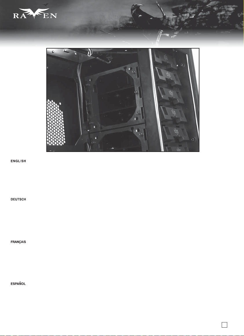
SERIES
SERIES
Q & A
Q: I purchased an all-in-one liquid CPU cooler, where should I install the radiator?
A: We recommend installing it in the rear side fan bracket in the 5.25” drive bay as shown in the illustration with the fan blowing air into the chassis.
There are three reasons:
A. The cooler can directly access colder air from outside of the chassis.
B. The position of the cooler will be next to the CPU to allow liquid tubing to reach easily.
C. Heated air from the radiator will be exhausted immediately by the 120mm top mounted fan.
F: Ich habe einen Alles-in-einem-CPU-Flüssigkeitskühler gekauft; wo soll ich ihn installieren?
A: Wir empfehlen, ihn an der hinteren Lüfterhalterung im 5,25 Zoll-Laufwerkseinschub (vgl. Abbildung) zu installieren,
wobei der Lüfter die Luft in das Gehäuse bläst.
Dies hat drei Gründe:
A. Der Kühler hat direkten Kontakt zur kühleren Luft an der Außenseite des Gehäuses.
B. Der Kühler befindet sich direkt neben dem Prozessor; der Flüssigkeitsschlauch ist leicht zugänglich.
C. Erhitzte Luft vom Kühler wird von dem im oberen Bereich installierten 120 mm-Lüfter umgehend ausgestoßen.
Q: J’ai acheté un kit de refroidissement liquide tout en un, où puis-je installer le radiateur?
R: Nous vous recommandons de l’installer dans le casier du ventilateur situé à l’arrière dans une baie 5.25” comme montré dans l’illustration,
avec le ventilateur dans le boîtier pour extraire l’air chaud.
Il y a 3 raisons :
A. Le radiateur peut accède directement à l’air frais de l’extérieur.
B. La position du radiateur sera très proche du processeur pour permettre une fixation des tubes aisée.
C. L’air chaud dégagé par le radiateur sera extrait immédiatement par le ventilateur de 120mm monté en haut.
P: Compré un líquido refrigerador para CPU todo en uno, ¿dónde debería instalar el radiador?
R: Le recomendamos que lo instale en el bracket para ventilador lateral trasero en la bahía para dispositivos de 5,25” como se muestra
en la ilustración con el ventilador moviendo aire hacia el interior del chasis.
Existen tres razones:
a. El disipador puede acceder directamente al aire frío del exterior hacia el chasis.
b. La posición del disipador será adyacente a la CPU para que el líquido llegue con mayor facilidad.
c. El aire caliente del radiador saldrá directamente gracias al ventilador superior de 120mm.
52
Page 54

SERIES
SERIES
Q & A
D: Ho acquistato un sistema di raffreddamento a liquido all in one, dove dovrei posizionare il radiatore?
R: Ti raccomandiamo di installare il radiatore nella parte posteriore del supporto ventola nei pressi dei bays da 5,25” come mostrato in figura,
con la ventola che soffia aria verso l’interno del case.
Ci sono tre ragioni:
A. Il radiatore sarà cosi raffreddato dall’aria più fresca proveniente dall’esterno del case.
B. La posizione del radiatore sarà cosi molto vicina alla CPU, favorendo l’allaccio dei tubi.
C. L’aria riscaldata dal radiatore potrà così essere espulsa immediatamente dalla ventola da 120mm montata nella parte alta.
Вопрос: Я приобрел процессорный кулер с жидкостным охлаждением типа «все в одном», где следует установить радиатор?
Ответ: Рекомендуется установить радиатор в кронштейн для вентиляторов на задней части отсека для 5,25-дюймовых приводов,
как показано на рисунке, так, чтобы вентилятор подавал воздух в корпус.
Для этого есть три причины:
A. На кулер будет
B. Кулер будет установлен рядом с ЦП для облегчения подсоединения тепловых трубок системы жидкостного охлаждения.
C. Нагретый воздух от радиатора будет мгновенно отводиться 120-мм вентилятором, установленным на верхней панели.
Q: 我購買最簡易的整合水冷散熱器, 水冷排安裝在哪邊比較適合?
A:
我們建議安裝在前進風後端, 原因如下:
A. 可以直接吸入機殼外部的冷空氣。
B. 跟CPU位置夠接近,水管長度受限小。
C. 廢熱會由上方的排風扇在第一時間排出。
Q: 我购买最简易的整合水冷散热器,水冷排安装在哪边比较适合?
A: 我们建议安装在前进风后端,原因如下:
A. 可以直接吸入机壳外部的冷空气。
B. 跟CPU位置够接近,水管长度受限小。
C. 废热会由上方的排风扇在第一时间排出。
непосредственно поступать более холодный воздух снаружи корпуса.
Q: オールインワンの液冷CPUクーラーを購入しましたが、どこにラジエターをインストールできますか?
A: 図示されるように、それをケース内に給気する向きのファンと共に、5.25”ドライブベイ内の後部側のファンブラケットにインス
トールするよう、お勧めします。
これには以下の3つの理由があります。
A. クーラーはケース外からより冷たい空気に直接接することができます。
B. クーラーの位置はCPUの隣で、液冷の配管が容易に達することが可能です。
C. ラジエターから排出された空気は、120mm上部設置のファンですぐ排出されます。
Q: All-In-One 수냉 CPU 쿨러를 구입했습니다. 라디에이터는 어디에 장착하나요?
A: 그림에서와 같이 5.25” 드라이브 베이 후면의 팬 브라켓에 설치하되, 팬이
이렇게 설치하는데는 세가지 이유가 있습니다.
A. 쿨러가 외부의 보다 차가운 공기와 직접 닿을 수 있도록 하기 위해.
B. 쿨러의 위치가 CPU 근처에 오게되어 수냉쿨러에 달려 있는 튜브들이 손쉽게 닿을 수 있습니다.
C. 라디에이터의 덥혀진 공기가 상부의 120mm 팬에의해 즉시 배기 될 수 있기 때문입니다.
케이스 안쪽으로 바람을 불 수 있도록 설치합니다.
53
Page 55

SERIES
SERIES
Q & A
Q: RV03 intake air primary from the bottom of the chassis, does it need to be raised further and will it suck in dust?
A: RV03’s foot stands have been tested and verified by SilverStone engineers to have optimal height for air intake, there is no need to raise it any further.
The RV03 also comes with filters that cover the entire intake area on the bottom of the chassis so it is very effective at keeping the dust out.
F: Das RV03 bezieht die Zuluft vorwiegend von der Unterseite des Gehäuses; muss es dazu weiter erhöht werden? Zieht es Staub an?
A: Die Standhöhe des RV03 wurde von SilverStone-Entwicklern getestet und als optimale Höhe zur Zuluft bestätigt; es gibt also keinen Grund,
das Gehäuse weiter zu erhöhen.Das RV03 wird mit Filtern geliefert, die den gesamten Zuluftbereich an der Unterseite des Gehäuses abdecken;
dadurch wird Staub effektiv abgehalten.
Q: L’admission d’air du RV03 est principalement assure par le dessous du boîtier, doit-il être surélevé pour ne pas être ennuyé par la poussière?
R: Les pieds du RV03 ont été testés et vérifiés par les ingénieurs de SilverStone pour avoir une hauteur optimale pour permettre une bonne ventilation,
il n’y a pas besoin de les surélever davantage. Le RV03 est aussi livré avec des filtres qui couvrent toute la zone d’admission du dessous du boîtier, ce
qui est très efficace pour empêcher à la poussière de s’introduire dans le boîtier.
P: La RV03 hace entrar aire sobre todo desde la parte inferior del chasis, ¿hay que elevarla para que no absorba polvo?
R: Los soportes de la RV03 han sido probados y verificados por ingenieros de Silverstone para tener una altura óptima para la entrada de aire,
luego no hay que elevarla más. La RV03 también viene con filtros que cubren toda la zona de entrada en la parte inferior del chasis, luego es muy
eficaz para mantener fuera el polvo.
D: In RV03 l’ingresso dell’aria proviene quasi esclusivamente dal basso, è necessario rialzarlo ulteriormente per migliorare il flusso dell’aria?
E per quanto riguarda l’ingresso della polvere?
R: I piedini d’appoggio di RV03 sono stati progettati per consentire la massima efficienza dei flussi d’aria, non c’è alcun bisogno di rialzare ulteriormente
il case. Non c’è motivo di preoccuparsi dell’ingresso della polvere: filtri specifici coprono interamente la zona di ingresso dell’aria con un’efficienza davvero
eccellente.
Вопрос: Воздух поступает в корпус RV03 в основном с нижней части корпуса. Следует ли устанавливать корпус на возвышении, и не будет ли
проникать пыль внутрь корпуса?
Ответ: Инженеры компании SilverStone испытали ножки корпуса RV03 и выбрали для них оптимальную высоту для поступления воздуха.
Нет необходимости устанавливать корпус на возвышении.Кроме того, корпус RV03 оснащен фильтрами
область впускных отверстий на нижней панели корпуса, обеспечивая максимально эффективную защиту от пыли.
, которые полностью закрывают
Q: RV03主要從底部進風, 需不需要再墊高機殼高度?會不會很容易吸進灰塵?
A: RV03腳墊的高度設計乃經過反覆驗證, 對散熱效果已達到最佳化高度, 不需要再特別墊高。
在機殼底部也安裝了大面積濾網, 因此不用擔心灰塵會跑進機殼內部, 濾網特殊的拆卸機構也讓清理過程簡易許多。
Q: RV03主要从底部进风, 需不需要再垫高机壳高度?会不会很容易吸进灰尘?
A: RV03脚垫的高度设计乃经过反复验证, 对散热效果已达到最佳化高度, 不需要再特别垫高。
在机壳底部也安装了大面积滤网, 因此不用担心灰尘会跑进机壳内部, 滤网特殊的拆卸机构也让清理过程简易许多。
Q: RV03の給気は基本的にケース底部から行われますが、ケースを特に持ち上げる必要がありますか?また塵を吸い込むことはないでしょうか?
A: RV03のフットスタンドはテストされており、給気のために最適の高さを持つようにSilverStoneのエンジニアによって確認されているので、
さらにそれを持ち上げる必要は全くありません。
RV03には、ケース底部の通気口エリア全体を覆うフィルタを備えており、ホコリの侵入を効率的に防ぎます。
Q: RV03의 흡기의 대부분이 케이스 바닥에서 이루어지는 것으로 아는데, 케이스를 좀 높여서 설치해야 하는지, 이럴 경우 먼지 흡입이 문제가 되진 않나요?
A: RV03의 하단 발판은, SilverStone의 엔지니어들이 고심하여 최적의 흡기가 이루어 질 수 있도록 설계
RV03은 케이스 하부의 흡기구 전체를 덮는 필터를 기본 제공하기 때문에 먼지가 유입되는것을 효과적으로 방지할 수 있습니다.
및 시험되었고 확인되었기에 높이를 높일 필요가 없습니다.
54
Page 56

SERIES
SERIES
Q & A
Q: There are venting holes on the back of RV03 so if I place it against the wall, will that affect cooling performance?
A: RV03’s design fully maximizes advantage offered by the 90 degree motherboard rotation by allowing users to place the chassis against the wall.
This is possible with the top cover allowing cables to be run through the top. The extra venting holes on the back of RV03 are only optional for systems
with multiple high heat output graphics cards.
F: An der Rückseite des RV03 befinden sich Belüftungsöffnungen; wird die Kühlleistung durch Aufstellung an einer Wand beeinträchtigt?
A: Das Design des RV03 maximiert den durch das um 90 Grad drehbare Motherboard gebotenen Vorteil, da es Benutzern ermöglicht, das Gehäuse
an einer Wand aufzustellen. Dies ist möglich, da aufgrund der oberen Abdeckung Kabel durch die Oberseite des Gehäuses geführt werden können.
Die zusätzlichen Belüftungsöffnungen an der Rückseite des RV03 dienen nur optional Systemen mit mehreren stark hitzeerzeugenden Grafikkarten.
Q: Il y a des trous de ventilation à l’arrière du RV03 donc est-ce que ca va affecter les performances de refroidissement si je le place à côté d’un mur?
R: La conception du RV03 maximise pleinement les avantages offert par un montage à 90° de la carte mère en permettant aux utilisateurs de placer le
boîtier contre un mur. Ceci est possible car le panneau supérieur permet de faire passer les câbles par le haut. Les trous de ventilation supplémentaires
situés à l’arrière du RV03 sont là uniquement en option pour les systèmes ayant plusieurs cartes graphiques dégageant beaucoup de chaleur.
P: Existen agujeros de ventilación en la parte trasera de la RV03 luego si la pongo contra un muro, ¿afectará a la refrigeración?
R: El diseño de la RV03 maximiza la ventaja ofrecida por la rotación de 90 grados de la placa base, permitiendo que los usuarios pongan el chasis
contra un muro. Esto es posible ya que la cubierta superior permite que los cables discurran por esa zona. Los agujeros de ventilación adicionales
en la parte trasera de la RV03 son sólo opcionales para sistemas con varias tarjetas gráficas que generen mucho calor.
D: Ci sono fori di ventilazione nella parte posteriore di RV03, se il case viene posizionato molto vicino ad un muro, questo influenzerà le
prestazioni di raffreddamento?
R: Il design di RV03trae il massimo vantaggio offerto dal posizionamento della scheda madre ruotata di 90° per cui è possibile posizionare
lo chassis con la parte posteriore molto vicina ad un muro. Il cover superiore inoltre, permette il passaggio dei cavi delle periferiche connesse
alla macchina proprio dall’alto, per cui appoggiare il case al muro non creerà alcun problema né al raffreddamento interno, né tantomeno alla
possibilità di connettere le periferiche. I fori di ventilazione presenti nella parte posteriori sono di supporto soltanto a sistemi che dispongano
di più di una scheda video.
55
Page 57

SERIES
SERIES
Q & A
Вопрос: На задней панели корпуса RV03 имеются вентиляционные отверстия. Если я поставлю корпус к стене, не снизится ли
эффективность охлаждения?
Ответ: В конструкции корпуса RV03 максимально использованы преимущества поворота материнской платы на 90 градусов, что позволяет
устанавливать корпус к стене. Это возможно благодаря тому, что верхняя крышка позволяет проложить кабели в верхней части корпуса
Дополнительные вентиляционные отверстия на задней панели корпуса RV03 предназначены только для систем с несколькими графическими
картами с высоким тепловыделением.
Q: RV03整台機殼可以向後方牆壁完全貼齊, 但背面有散熱孔, 會不會因此影響散熱?
A: 主機板旋轉90度的優勢之一, 就是能將整個主機向後靠到底, 而線材由上方接出。這樣的設計是為了在有限空間中, 依然能使用硬體強大的電腦系統。
在RV03中, 後方的通風孔主要是為了極端高耗電量的顯示卡, 且在兩張或以上的顯示卡同時運作時, 作為輔助散熱用。因此在一般使用狀況下,
不需擔心貼齊牆壁等障礙物而產生的散熱效能衰減。
Q: RV03整台机壳可以向后方墙壁完全贴齐,但背面有散热孔, 会不会因此影响散热?
A: 主机板旋转90度的优势之一, 就是能将整个主机向后靠到底, 而线材由上方接出。这样的设计是为了在有限空间中, 依然能使用硬件强大的计算机系统。
在RV03中, 后方的通风孔主要是为了极端高耗电量的显示卡, 且在两张或以上的显示卡同时运作时, 作为辅助散热用。因此在一般使用状况下,
不需担心贴齐墙壁等障碍物而产生的散热效能衰减。
Q: RV03後部に通気口があるので、壁を背にして設置すると、冷却性能に影響するでしょうか?
A: RV03は、マザーボードを90度回転させることで実現した利点を最大化するように設計されており、ユーザが壁を背にしてケースを置くことを
可能にしています。これは、ケーブルが上面を通して配線されたケースカバーによって可能となります。 RV03後部の特別な通気口は、高温を出
すグラフィックカード複数を装着したシステム構成のみを対象としています。
.
Q: RV03에 배기구가 있는데, 벽에 붙여 놓을 경우 냉각성능에 영향을 줄까요?
A: RV03 의 디자인은 90도 기울어진 메인보드의 장점을 최대한 활용할 수 있도록 디자인되어 사용자들이 벽에 붙여 놓고도 사용이 가능합니다.
이는 상부 커버가 케이블
필요한 옵션 사항입니다.
위쪽으로 지나 갈 수 있기에 가능합니다. RV03의 뒤쪽에 있는 추가 배기구는 다수의 그래픽 카드의 여분 배출을 위해
56
Page 58

SERIES
SERIES
Q & A
Q: I feel the included Air Penetrator AP181 fans are still not quiet enough for me at default low speed setting, can I use a fan controller or other methods
to lower fan speed further?
A: The Air Penetrator AP181 fans use industry standard 3pin fan connectors so they will work with most fan controllers available on the market or with
motherboards and any methods of voltage reducing mechanisms. The starting voltage for AP181 at low speed setting requires about 10.8V, which some
fan controllers may not support properly. So when connecting to fan controller, it is best to flip the case’s fan speed switch to high setting to enable lower
starting voltage. At 5V for example, the fan speed will be at around 500rpm, which is nearly inaudible. When connecting to motherboard for fan speed
control, if AP181 appears to have trouble starting, it may be due to motherboard detecting low temperature and supply too little voltage. To solve this
problem, please change the motherboard fan speed or temperature setting from within the motherboard BIOS or flip the case’s fan speed switch to high setting.
F: Ich empfinde die Betriebsgeräusche der mitgelieferten Air Penetrator-Lüfter AP181 bei den geringen Standardgeschwindigkeitseinstellungen immer noch
als zu laut; kann ich eine Lüftersteuerung oder andere Methoden zur weiteren Reduzierung der Lüftergeschwindigkeit nutzen?
A: Die Air Penetrator-Lüfter AP181 nutzen genormte (Industriestandard) 3-polige Lüfteranschlüsse, sodass sie mit den meisten Lüftersteuerungen oder
Motherboards auf dem Markt sowie jeglichen Methoden zur Spannungsreduzierung kompatibel sind. Die Anfangsspannung des AP181 bei geringen
Geschwindigkeitseinstellungen beträgt ca. 10,8 V, was von einigen Lüftersteuerungen möglicherweise nicht richtig unterstützt wird. Daher empfiehlt sich
beim Anschließen an der Lüftersteuerung, den Lüftergeschwindigkeitsschalter des Gehäuses zur Erzielung einer geringeren Anfangsspannung auf eine
hohe Einstellung anzupassen. Bei 5 V zum Beispiel beträgt die Lüftergeschwindigkeit ca. 500 U/min, was nahezu nicht hörbar ist. Bei der
Geschwindigkeitssteuerung des Lüfters durch Anschließen am Motherboard kann der AP181 Startprobleme aufweisen; dies wird dadurch verursacht,
dass das Motherboard geringe Temperaturen erkennt und das Gerät mit zu geringer Spannung versorgt. Bitte ändern Sie zur Lösung dieses Problems
die Motherboard-Lüftergeschwindigkeit bzw. die Temperatureinstellungen über das Motherboard-BIOS; alternativ können Sie den Lüftergeschwindigkeitsschalter
des Gehäuses auf eine hohe Einstellung anpassen.
Q: Je pense que les ventilateurs Air Penetrator AP181 inclus ne sont pas assez silencieux pour moi à la vitesse la plus basse, puis-je utiliser un régulateur
ou d’autres méthodes pour les ralentir davantage ?
R: Les ventilateurs Air Penetrator AP181 utilisent des connecteurs à 3 broches standard de l’industrie qui fonctionneront avec la plupart des contrôleurs de
ventilateur disponible sur le marché ou avec des cartes mères et d’autres mécanismes de régulation du voltage.Le voltage de départ requis pour l’AP181 à
vitesse basse est d’environ 10.8V, ce que certains contrôleurs ne supportent pas correctement. Donc lorsque vous branchez un contrôleur de ventilateur,
c’est mieux de mettre la vitesse haute sur l’interrupteur du boîtier pour permettre au ventilateur de commencer à tourner. A 5V par exemple, la vitesse de
rotation du ventilateur sera aux alentours de 500 tpm, ce qui est presque inaudible.Lorsque vous le branchez au contrôleur de la carte mère, il apparait que
l’AP181 a parfois des problèmes pour démarrer sa rotation, c’est lié au fait que la carte mère détecte une température faible et ne fournit donc pas assez de
courant. Pour résoudre ce problème, veuillez changer le paramètre de vitesse ou de température dans le BIOS ou mettez l’interrupteur de vitesse du boîtier
sur la position haute.
P: Me parece que los ventiladores incluidos Air Penetrator AP181 siguen sin ser lo bastante silenciosos para mí según la velocidad baja por defecto,
¿puedo usar un controlador para el ventilador o algún otro método para reducir aún más la velocidad del ventilador?
R: Los ventiladores Air Penetrator AP181 usar conectores estándar de 3 pines luego funcionarán con la mayoría de los controladores para ventilador
disponibles en el mercado ó con placas base y cualquier método ó mecanismo para reducir el voltaje. El voltaje inicial para el AP181 a baja velocidad
precisa de unos 10,8V, algo que algunos controladores para ventilador no pueden manejar. Por tanto, cuando se conecta al controlador para ventilador,
es mejor situar el interruptor de velocidad para ventilador de la carcasa en el nivel alto para permitir un voltaje inicial menor. Por ejemplo a 5V, la velocidad
del ventilador será de unas 500rpm, algo casi inaudible. Cuando se conecta a la placa base para controlar la velocidad del ventilador, si el AP181 parece
tener problemas para arrancar, podría deberse a que la placa base detecta una baja temperatura y suministra un voltaje bajo. Para solventar este problema
cambie por favor la velocidad del ventilador de la placa base ó el interruptor de temperatura desde la BIOS de la placa base o sitúe el interruptor de velocidad
del ventilador de la carcasa en el nivel alto.
D: Le ventole Air Penetrator AP181 non sono ancora abbastanza silenziose per me, anche se settate a bassa velocità. E’ possibile utilizzare un fan
controller o altri metodi per ridurne ulteriormente la velocità di rotazione?
R: Le ventole Air Penetrator AP181 utilizzano connettori a 3 pin standard per cui possono essere collegate ad un fan controller, alla scheda madre o
ad altri dispositivi di riduzione della tensione di alimentazione. La tensione di partenza per le AP181 settate a bassa velocità è di circa 10.8V, che alcuni
controller possono non supportare correttamente. Quindi, quando connettete la ventola ad un fan controller, è opportuno spostare la levetta dell’interruttore
di regolazione del case su HIGH per poter usufruire di più basse tensioni di partenza. A 5V, ad esempio, la velocità della ventola sarà di circa 500rpm e la
rumorosità vicina alla soglia dell’inudibile. Quando connettete la ventola alla scheda madre per la regolazione della velocità di rotazione, AP181 potrebbe
avere difficoltà a partire; questo può dipendere dal fatto che la scheda madre registra temperature basse e fornisce di conseguenza alla ventola una tensione
insufficiente. Per risolvere questo problema, modificate le impostazioni della regolazione della velocità della ventola nel bios o spostate la levetta dell’interruttore
di regolazione del case su HIGH.
57
Page 59

SERIES
SERIES
Q & A
Вопрос: Мне кажется, что входящие в комплект поставки вентиляторы Air Penetrator AP181 все же недостаточно тихо работают в стандартном режиме
низкой скорости. Можно ли использовать контроллер вентиляторов или другие способы для дальнейшего снижения скорости вращения вентиляторов?
Ответ: Вентиляторы Air Penetrator AP181 оснащены стандартными 3-контактными разъемами, поэтому они совместимы с большинством имеющихся в
продаже контроллеров вентиляторов и материнских
вентиляторов AP181 в режиме низкой скорости составляет приблизительно 10,8 В. Некоторые контроллеры вентиляторов могут не поддерживать такое
напряжение надлежащим образом. Поэтому, при подключении вентиляторов к контроллеру желательно выбрать режим высокой скорости с помощью
переключателя скорости вентиляторов на корпусе, чтобы
В скорость вентилятора составляет приблизительно 500 об/мин, то есть вентилятор работает почти бесшумно.При подключении вентиляторов к
материнской плате для управления их скоростью, если вентиляторы AP181 не запускаются, это может быть следствием обнаружения материнской
платой низкой температуры и подачи слишком низкого напряжения
настройку температуры на материнской плате посредством BIOS материнской платы или выберите режим высокой скорости с помощью переключателя
скорости вентиляторов на корпусе.
Q: 我覺得AP181在低轉時依然不夠安靜, 可以透過風扇控制器或其他方式降低轉速嗎?
A: AP181的連接埠為一般3Pin規格, 可以接上大部分的溫控調速器、主機板或其他裝置, 以降低電壓的方式調整轉速。
要注意的地方在於啟動電壓
如果有需要接調速器, 必須把機殼開關調整為High以獲得更低的啟動電壓。一般來說, 電壓降到5V轉速大約到500rpm, 此時的噪音量幾乎小到聽不到。
另外需要提醒, 如果接到主機板時卻風扇如果啟動不良, 也有可能是主機板的溫控預設被開啟所導致的。您可以透過BIOS解除溫控, 或是直接把機殼上
的開關調整為High的狀態來解決。
Q: 我觉得AP181在低转时依然不够安静, 可以透过风扇控制器或其它方式降低转速吗?
A: AP181的连接端口为一般3Pin规格,可以接上大部分的温控调速器、主机板或其它装置, 以降低电压的方式调整转速。
要注意的地方在于启动电压, AP181在低转速(Low)状态下,启动电压高达10.8V,一般调速器的启动电压较低会较难启动。
如果有需要接调速器, 必须把机壳开关调整为High以获得更低的启动电压。一般来说, 电压降到5V转速大约到500rpm, 此时的噪音量几乎小到听不到。
另外需要提醒, 如果接到主机板时却风扇如果启动不良, 也有可能是主机板的温控预设被开启所导致的。您可以透过BIOS解除温控, 或是直接把机壳上
的开关调整为High的状态来解决。
, AP181在低轉速(Low)狀態下, 啟動電壓高達10.8V, 一般調速器的啟動電壓較低會較難啟動。
плат, а также к ним применимы любые способы снижения напряжения. Напряжение запуска для
можно было использовать более низкое напряжение запуска. Например, при напряжении 5
. Для решения этой проблемы измените скорость вращения вентиляторов или
Q: 付属のAir Penetrator AP181ファンは、デフォルト低速度設定でも十分に静かではないと感じます。ファンコントローラまたはファン回転速度を下げる
他の方法をさらに使うことができますか?
A: Air Penetrator AP181ファンは業界標準の3ピンファンコネクタを使うので、市場で入手可能なほとんどのファンコントローラ、またはマザーボード、
さらにその他の電圧減少メカニズムを併用しても作動します。低速度設定のAP181の始動電圧には約10.8Vを必要とし、ファンコントローラによっては
適切にサポートされないものもあります。それで、ファンコントローラを接続する時は、低めの始動電圧を可にするために高い設定のケースファン速度
スイッチを切替えるのがよいでしょう。例えば5Vでは、ファン回転速度は約500rpmになり、動作音はほとんど聞こえません。ファン速度制御のために
マザーボードと接続する時、AP181の始動に困難があるならば、それはマザーボードが低温を検出した結果低すぎる電圧を供給するのが理由かもしれません。
この問題を解決するには、マザーボードBIOS内からマザーボードファン回転速度または温度設定を変更するか、ケースのファン速度スイッチを高めの設定に
切替えてください。
Q: 기본제공되는 Air Penetrator AP181팬이 최저 속도에서 정숙하지 못한것 같은데, 팬컨트롤러나, 기타 다른 방법으로 팬 속도를 더 낮추어도 되나요?
A: Air Penetrator AP181팬은 업계 표준의 3핀 커넥터를
API 181팬의 저속에서의 기동 전압은 약 10.8V를 요구하며, 특정 팬 컨트롤러는 제대로 지원할 수 없을 지도 모릅니다. 그러므로, 팬 컨트롤러를 설치할때,
케이스의 팬 스위치를 고속으로 세팅하고 설치한 후, 추가로 팬 전압을 낮출 수 있도록 합니다. 예를 들어
만약 메인보드에서 팬 속도를 조절하는 경우 팬이 기동되지 않는 문제가 발생할 수 있습니다. 이 문제를 해결하기 위해 메인보드 바이오스에서 메인보드 팬 속도나,
온도 설정을 변경하거나, 케이스의 팬 스피드 스위치를 “High”로 설정하는 방법을 사용합니다.
사용해 시장에 나와있는 대부분의 팬 컨트롤러나, 메인보드의 전압 조정 방법등 대부분의 방법과 호환 됩니다.
5V의 경우 팬 속도는 약 500rpm으로 거의 들리지 않습니다.
58
Page 60

lssue date: February, 2011
NO.: G11213400
 Loading...